Article

Comparison of the Cathodic Protection of Epoxy Resin Coating/Zinc-Rich Coatings on Defective Areas under Atmospheric and Immersion Conditions: The Secondary Activation of Zinc Particles

1
School of Chemical Engineering and Technology, Sun Yat-sen University, Zhuhai 519082, China
2
Southern Marine Science and Engineering Guangdong Laboratory (Zhuhai), Zhuhai 519082, China
3
National & Local Joint Engineering Research Center of Harbor Oil & Gas Storage and Transportation Technology, Zhejiang Key Laboratory of Petrochemical Environmental Pollution Control, School of Petrochemical Engineering & Environment, Zhejiang Ocean University, Zhoushan 316022, China
4
Offshore Oil Engineering Co., Ltd., Tianjin 300451, China
5
Jiangsu Key Laboratory of Marine Bioresources and Environment, Jiangsu Ocean University, Lianyungang 222005, China
6
Co-Innovation Center of Jiangsu Marine Bio-Industry Technology, Jiangsu Ocean University, Lianyungang 222005, China
*
Authors to whom correspondence should be addressed.
Coatings 2024, 14(3), 336; https://doi.org/10.3390/coatings14030336
Submission received: 16 February 2024 / Revised: 8 March 2024 / Accepted: 11 March 2024 / Published: 12 March 2024
(This article belongs to the Special Issue Investigation on Structure and Corrosion Resistance of Steels/Alloys)

Abstract

:
The cathodic protection provided by epoxy coating/epoxy zinc-rich coatings on defective areas under atmospheric and immersion conditions was studied via a Q235 wire beam electrode (WBE), scanning electron microscopy, X-ray diffraction, and surface morphology analysis. The results showed that the cathodic protection processes under the two test conditions displayed significant differences. The effective protection time of the defective area under the atmospheric condition was 1.7 times that under the immersion condition. Compared with the immersion condition, zinc particles in zinc-rich coatings under the atmospheric condition exhibited higher cathodic protection efficiency. The possible activation mechanism of zinc particles under the two conditions was elucidated.

1. Introduction

Atmospheric corrosion is a corrosion phenomenon with a wide influence range, significant corrosion loss, numerous influencing factors, and complex action mechanisms [1,2,3]. Owing to the absence of a large amount of electrolyte solution, the traditional sacrificial anode and applied current technology in soil, seawater, and other environments cannot be used for long-term protection in the atmosphere [4]. Therefore, organic coatings have become the most economical and effective protection technology used for delaying the corrosion of steel structures in an atmospheric environment [5,6]. To further improve its protective performance, the organic coating can be endowed with cathodic protection through the addition of active metal particles. In the early 1930s, scientists discovered that adding zinc powder to an organic coating could provide adequate cathodic protection even after slight damage to the surface coating [7].
Epoxy zinc-rich coatings (ZRCs) can protect the base metal from corrosion through shielding and cathodic protection, and they are still one of the most effective and widely used anticorrosive coatings in industrial and marine environments [8,9]. At present, epoxy zinc-rich coatings have been widely used in offshore engineering such as cross-sea bridges and oil platforms [10]. The shielding effect is attributable to the polymer coating and the corrosion products generated through the anodic dissolution of internal zinc powder particles [11] (which may be due to the self-corrosion of zinc particles or the cathodic protection of corrosion cells), including Zn(OH)2, ZnO, and Zn5 (OH)8Cl2H2O [12,13]. Cathodic protection is attributable to the potential difference between zinc particles and substrates. Zinc potential is more negative than the metal substrate, so zinc easily loses electrons to become the anode, and the substrate is the cathode. In the anode region, zinc is corroded due to the loss of electrons. In the cathode region, the substrate is protected because of the electrons obtained. Because the electrolyte solution penetrates the coating/substrate interface, zinc powder particles and substrate metals can form a galvanic cell, thereby protecting the substrate from corrosion [8,9].
Previous studies have shown that zinc particles in ZRCs reduced the intermolecular adhesion and density of the epoxy resin to a certain extent, making the coating porous and easy to penetrate by the electrolyte [14,15]. Cathodic protection is the primary evaluation standard for the protective performance of ZRCs compared with the blocking of zinc powder corrosion products. Therefore, in the marine atmospheric environment, ZRC primers are used to protect steel structures from corrosion [4,16].
Dissolved oxygen plays a vital role in the protection processes of ZRC through the inhibition of the penetration of the corrosive medium and cathodic protection. For example, zinc powder particles undergo corrosion (Equations (1), (3) and (4)) because the electrolyte solution can penetrate their surface layer. At this time, the zinc particles are in an activation state [17]. Although this reaction occurs on the surface of zinc particles, they play a vital role in cathodic protection processes [11,12] because the reduction reaction of oxygen on the surface of zinc particles forms a local strong alkaline environment. This can promote the dissolution of the semiconductor film zinc oxide covered by the surface of zinc particles (Equation (2)), and an electron channel with lower resistance between zinc particles and the matrix metal is formed. Moreover, the corrosion products can hinder the further diffusion of the electrolyte and dissolved oxygen into the coating, thereby retaining the remaining part of the zinc particles, which provide a basis for long-term cathodic protection [18].
O2 + 2H2O + 4e → 4OH
ZnO + 2OH → ZnO22− + H2O
Zn → Zn2+ + 2e
Zn2+ + 2OH → Zn(OH)2
The activation of zinc particles in ZRCs is beneficial to cathodic protection. However, a higher dissolved oxygen concentration in the coating will hinder cathodic protection time. Excessive consumption of zinc powder particles will reduce the cathodic protection time [19]. Several corrosion products can adhere to the surface of zinc particles, leading to higher resistance between zinc powder particles and base metals [20,21]. The volume expansion of corrosion products will lead to the rotation and displacement of zinc particles, which will destroy the electronic channel between zinc particles and the substrate [22]. Therefore, these factors affect the diffusion of dissolved oxygen into the coating, and the reduction reaction rate will affect the duration and efficiency of the cathodic protection of ZRCs [23].
Presently, single-layer coatings are the most popular research topic in the cathodic protection evaluation of ZRCs. However, in practical application, ZRCs are used as primers with topcoat and intermediate paint to form an anti-corrosion system [24,25]. For example, fluorocarbon resin is used as the top coat for offshore wind power coating systems and can exhibit excellent aging resistance; the middle paint is the epoxy mica iron, which mainly plays the role of bonding; and ZRCs, as the last defense, play a cathodic protection role owing to the occurrence of the electrochemical reaction at the interface of the substrate [24,26]. Because the barrier effect of the composite coating on corrosive medium penetration and dissolved oxygen diffusion is significantly different from that of a single-layer coating, it will significantly affect the reduction reaction rate of dissolved oxygen and the cathodic protection efficiency [27,28,29]. Therefore, investigating the activation process of zinc powder particles under composite coatings and their cathodic protection on the substrate is vital.
Atmospheric corrosion is the local corrosion damage caused by chemical or electrochemical action. Wire beam electrode (WBE) echnology has an important application in the field of local corrosion research [30]. Zhong et al. used WBE technology to study the corrosion behavior of mild steel and copper in salt solution, and the results showed that the distribution of corrosion potential under thin liquid film presented an obvious uneven distribution compared with that under a full immersion state, and the corrosion potential changed significantly with the corrosion time [31]. Liu used WBE technology to study the influence of liquid film thickness on the corrosion rate of A3 steel, which directly reflected the changing relationship between the corrosion rate and liquid film thickness [19]. Xia et al. used WBE technology to study the cathodic protection of defect areas offered by zinc-rich coatings (ZRCs) under immersion and liquid film conditions. Compared with traditional sheet electrodes, WBEs can provide information on the surface current density distribution and zinc powder activation, polarization, and polarity reversal processes during the cathodic protection phase of ZRCs [32,33]. However, WBE technology provides less information on the electrode–solution interface, which makes it difficult to further analyze the corrosion mechanism and meet the needs of some research work. In the future, it needs to be combined with other research methods and testing techniques to enrich the data types and electrode process dynamics information.
In this study, the cathodic protection of epoxy resin coating/zinc-rich coatings (ER/ZRCs) on defective areas under thin liquid film (thickness 750 μm) and immersion (3.5% sodium chloride solution) conditions was studied via a wire beam electrode (WBE), scanning electron microscopy (SEM), X-ray diffraction (XRD), and a three-dimensional depth of field. According to the open-circuit potential (OCP) of the composite coating system and the change law of the cathodic protection current in defective areas, the difference in and the mechanism of the zinc particle consumption of zinc-rich primers under immersion and thin liquid film conditions were analyzed. The hypothesis we studied was that the cathodic protection process of composite coatings under atmospheric liquid film has novelty. We studied these aspects because the current research mainly focuses on the performance of single-layer zinc-rich coatings, while in actual engineering, zinc-rich coatings are only used as the primer, and the intermediate layer and top coat have an important impact on its cathodic protection effect, especially on the activated dissolution and cathodic protection process of primer zinc powder, but this factor has not been considered.

2. Experiment

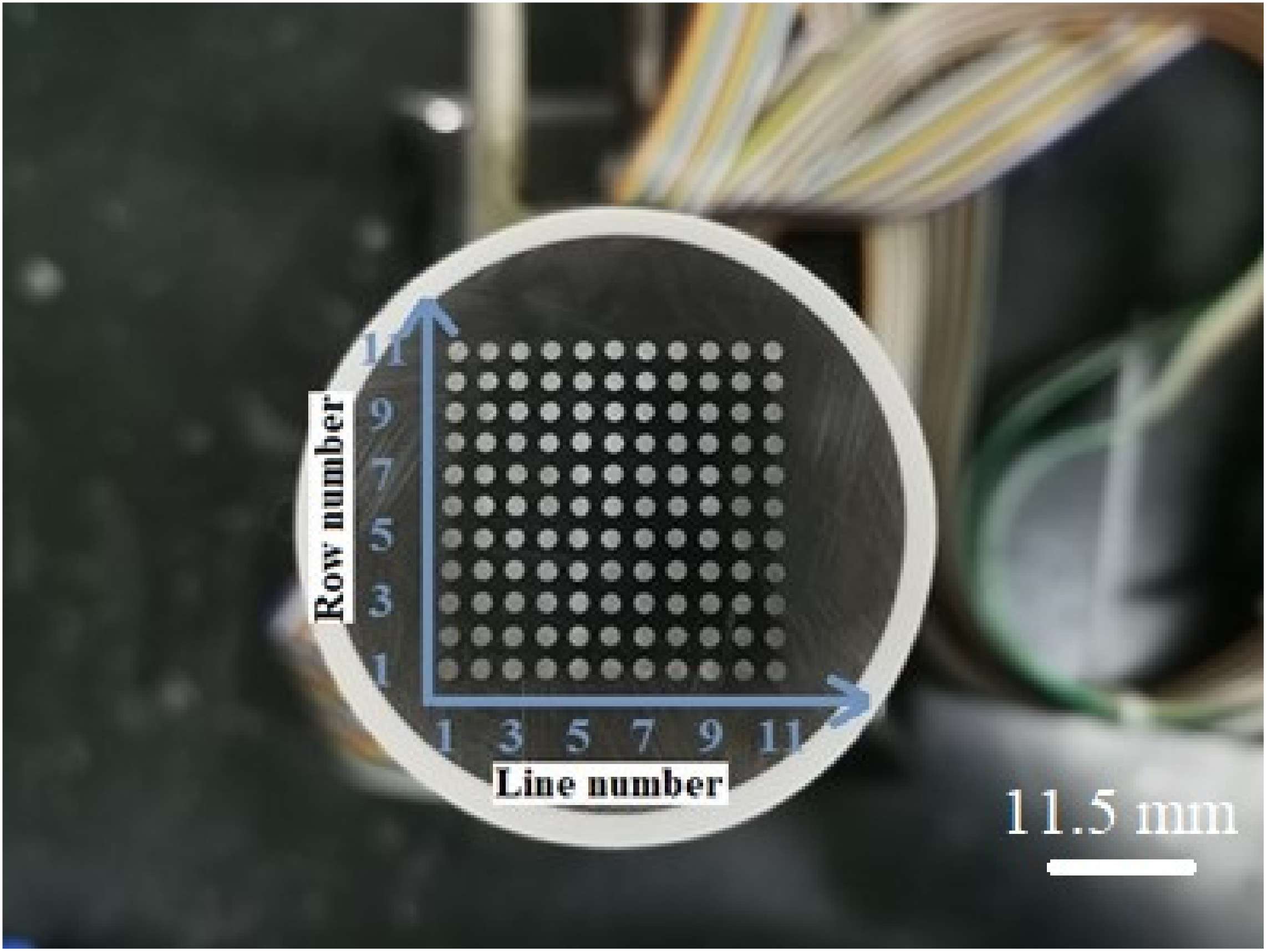
2.1. Preparation of the WBE and Composite Coating

One hundred and twenty-one (121) carbon steel wires (material: Q235; diameter: 1.5 mm) were arranged in an array of 11 × 11 and sealed with an epoxy zinc-rich primer, and each wire was separated by 1.0 mm (Figure 1). The area of a single carbon steel wire was 1.77 mm2, and the total area of the wire beam electrode was 213.69 mm2. The electrode surface was abraded with 600–1200# silicon carbide papers on an automatic metallographic polishing machine and cleaned with ethanol and acetone. The epoxy zinc-rich primer was coated on the electrode surface and cured at room temperature for 7 days. Then, the epoxy resin (E44) was coated on the epoxy zinc-rich primer and cured for 7 days to prepare the epoxy/epoxy zinc-rich composite coating.
The coating thickness was measured using a coating thickness gauge (EC-770, Yuwen Sensor, Shenzhen, China). The result revealed that the thicknesses of the composite coating and zinc-rich primer (Xuanwei (Shanghai) Coatings Co., Ltd.) were 200 ± 10 and 140 ± 10 µm, respectively. The zinc powder content of the zinc-rich primer was 75%, and the zinc-rich primer was purchased from Xuanwei Company, Shanghai, China. A wallpaper blade (0.28 mm blade thickness) was used to create scratches on the coatings surface to expose the base metal. The artificial scratch was 9.0 mm in length. The artificial defect positions were 4–6# (the 4–6# electrode was in the 4th row and 6th column, the same as below), 5–6#, 6–6#, and 7–6# electrodes under atmospheric thin liquid film and immersion conditions.

2.2. Simulation Device for the Atmospheric and Immersion Experiment

The working electrode surface was tilted by 45° and covered with a 750 μm thick absorbent filter paper, which was slowly wetted with a 3.5 wt.% NaCl solution using a dropping funnel. The funnel was regularly refilled with a solution to ensure that the thickness and concentration of the liquid film did not change during evaporation in the atmosphere. The droplet flow rate at the lower end of the filter paper was 6–8 drop/min. The specific device layout of the liquid film condition can be seen in a previous study [32]. The immersion condition involves soaking the WBE in a 3.5 wt.% of NaCl solution.

2.3. WBE Method

The WBE test was conducted using modular instruments. Before each test was performed, all electrodes in the WBE were connected. At the beginning of the potential distribution test, all electrodes were disconnected from each other, and the corrosion potentials of each electrode were measured in sequence. The standard three-electrode system was used in the test. The WBE was the working electrode (WE). The reference electrode (RE) was a saturated calomel electrode (SCE), and a platinum electrode with a side length of 10 mm was used as the counter electrode (CE). At the beginning of the current distribution measurement, the measured electrode was disconnected from the others, and the current between the individual electrodes and the other connected electrodes was measured. Subsequently, the measured electrode was reconnected to the other electrodes, the next electrode was disconnected, and the procedure was repeated. All measurement results for the WBE were plotted using Surfer 8.0 software.

2.4. Characterization

Scanning electron microscopy (SEM, 165 JSM-IT 200, Tokyo, Japan) was used to observe the cross-sectional surface morphology of the ER/ZRCs before and after the experiment. Before the SEM observation was conducted, the sample surface was sprayed with gold to enhance the conductivity of the coating. After the experiment was conducted, the corrosion morphology of the metal substrate under the coating was observed using a Leica DVM6 three-dimensional ultra-depth microscope. An X-ray diffractometer (XRD, UltimaIV, Tokyo, Japan) was used to identify the main phases in corrosion products at a scanning angle of 5–90° and a scanning speed of 5°/min.

3. Results and Discussion

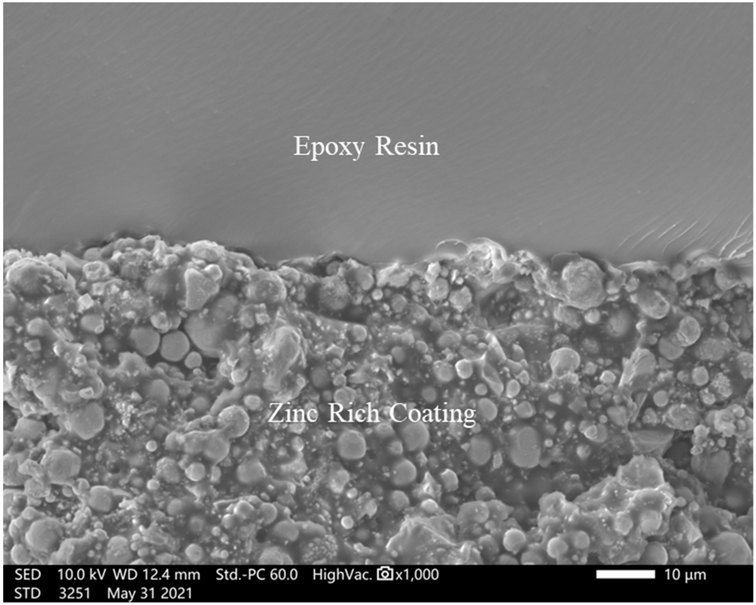
3.1. Morphological Analysis

Figure 2 shows a cross-sectional SEM image of the ER/ZRCs before the experiment was conducted. The coatings were divided into two layers. The upper layer contained ERs, and the lower layer contained ZRCs. No bubbles and other inclusions occurred between the surface layer and the bottom layer; thus, the interface bonding was relatively tight. ZRCs contained a large number of accumulated zinc particles with a particle size range of 2–6 μm, and the zinc particles closely overlapped [33].

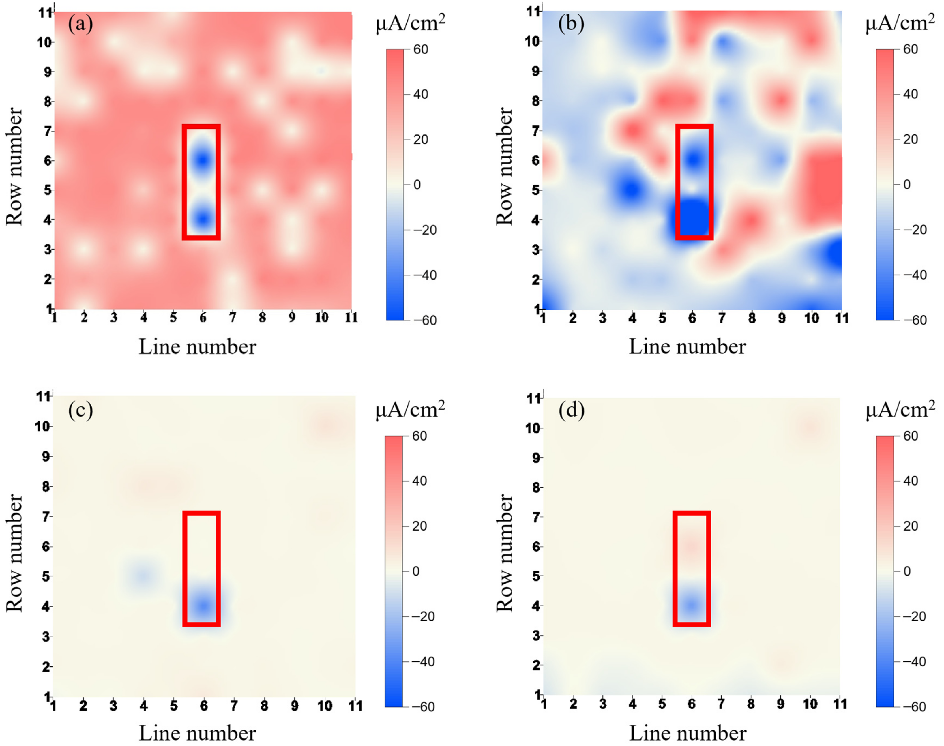
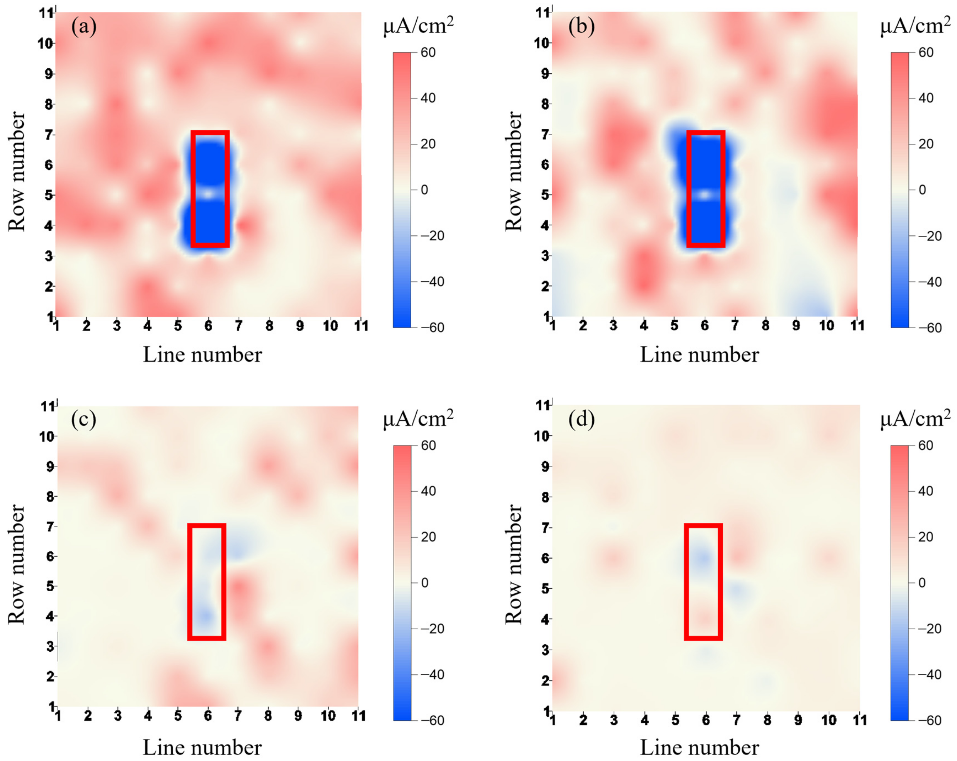
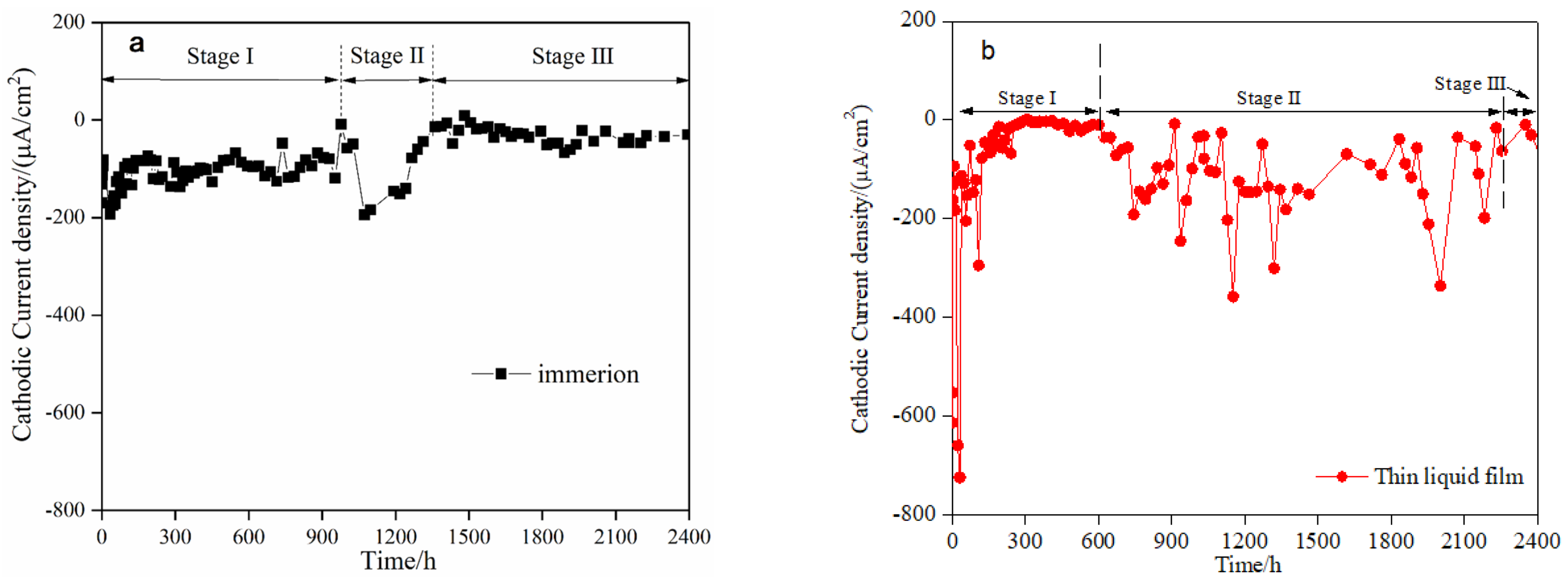
3.2. Current Distribution of the WBE

The current density distribution on the WBE surface and its change characteristics with time under immersion and atmospheric thin liquid film conditions is shown in Figure 3 and Figure 4. The negative value on the right scale indicates the cathode current and the positive value indicates the anode current.
The current density distribution on the surface of the node electrode at a typical time under immersion conditions is shown in Figure 3. Higher cathodic protection currents of 64.16 and 67.33 μA/cm2 were detected in defective areas of 4–6# and 6–6# electrodes after 1 h, respectively. After 1 h, a flaky anode reaction area was detected on the electrode surface, and the maximum value was 48.75 μA/cm2 for 6–10# electrodes near the defective area. This indicated that at the initial stage of the immersion test, the carbon steel matrix in the defective area and ZRCs formed a corrosion galvanic cell, and zinc powder particles were dissolved as anodes (Equation (1)) to transfer electrons to the exposed metal substrate in the defective areas. The electrons obtained by dissolved oxygen in the defective area underwent a reduction reaction (Equation (2)) to protect the defective areas. Because the surface of ZRCs was covered with ERs with a thickness of 200 μm, the electrolyte solution could not directly penetrate ZRCs from the ER surface. Therefore, the protective current obtained in the defective area results from the electrolyte solution penetrating ZRCs laterally along the defective areas, thereby activating zinc particles to corrode and dissolve [9].
At a protection time of 24 h, the cathodic protection current density of 4–6# and 6–6# electrodes in the defective area rapidly increased by 194.62 and 73.50 µA/cm2, respectively. At the same time, the whole electrode surface exhibited a strong cathode reaction area except for a few high anode reaction points. Owing to the activation of zinc powder in ZRCs, the electrodes exhibited a higher cathodic protection current density.
At a protection time of 1314 h, the current of the 6–6# electrode in the defective area changed from cathode to anode. The anode current density was 0.45 µA/cm2, indicating that ZRCs could not provide effective protection for the defective areas. The intensity of the cathodic reaction was weak on the electrode surface (Figure 3c). After 1314 h, the defective area displayed a higher anode corrosion current density. For example, the anode current density of the 6–6# electrode was 10.20 µA/cm2 at 2400 h.
According to the abovementioned results, under the immersion condition, the protective current of zinc powder particles in ZRCs was obtained in the defective areas at the initial stage of immersion and a protection time of 1314 h.
The changing trend of current density distribution on the electrode surface with time under the thin liquid film is shown in Figure 4. Similar to the solution immersion condition, the defective areas appeared as cathodes after 1 h, indicating that the area was protected by the current from zinc particles and was free from corrosion (Figure 4a). The cathode current density of the defective areas under the atmospheric liquid film condition was much higher than that in solution immersion. For example, the current densities of 4–6# and 7–6# electrodes were −130.46 and −345.98 µA/cm2, respectively. After 24 h, the activation degree of zinc powder was enhanced, the anodic reaction area on the electrode surface was continuously enlarged, and the cathodic protection current density of the defective area rapidly increased. For example, the current density of 4–6# increased by 316.20 µA/cm2. Compared with the solution immersion condition, the phenomenon of a higher cathodic protection current in the initial stage of the defect area under the atmospheric liquid film condition occurred in single ZRCs (75%) [33]. This indicated that the dissolved oxygen concentration in the thin liquid film was high and oxygen consumption could be replenished; therefore, the zinc particles in ZRCs exhibit a higher activation speed, a higher activation degree, and a higher cathodic protection current density for defective areas [11].
After 24 h, although the defective area remained in the cathode reaction area, the cathode current gradually decreased. After 624 h, the maximum cathode current density of the defect area at the 4–6# electrode was 6.11 µA/cm2 (Figure 4c). The cathodic protection current density of the defect area gradually increased, reaching its maximum after 1512 h; for example, the current density of the 5–6# electrode was −539.70 µA/cm2. Then, the cathodic protection current density of the defective area gradually decreased after 1512 h. After 2231 h (Figure 4d) until the end of the experiment (2400 h), the electrode 4–6# was converted into an anode, and the electrode current density was 16.59 µA/cm2 at 2231 h. The anode current point present in the defective areas indicated that ZRCs could not provide effective protection, and the base metal began to corrode [20].
The changing trends of cathode current density with time in the defective areas during the whole experiment are shown in Figure 5. According to the change characteristics of cathodic protection current density, the cathodic processes of ER/ERCs were classified under immersion and atmospheric liquid film into three stages; the first stage of activation (stage I); the second stage of activation (stage II); and the third stage of cathodic protection failure (stage III). Under the immersion condition, in the stage I activation of ER/ERCs (0–1026 h), after 35 h, the cathodic protection current density of the defective areas rapidly increased and reached the maximum value of 192.92 µA/cm2. After 1026 h, the current density of the defective areas gradually decreased, and its peak value was 49.32 µA/cm2. The stage II activation of ER/ERCs occurred at 1026–1314 h. After 1074 h, the cathodic protection current density of the defective area first increased, then decreased, and reached its peak value of 194.05 µA/cm2. After 1314 h, stage III of cathodic protection failed. The anode current reaction occurred in the 6–6# defective area, and ZRCs lost their effective protection to the defective areas.
Similar to the immersion condition, the cathodic protection current density of the defective area under the liquid film condition occurred in three stages. During stage I activation of 0–624 h, the peak cathodic protection current density of the defective area was 725.03 µA/cm2, which is about 2.5 times that under the same stage of immersion conditions. During stage II activation of 648–2231 h, the peak current density was 336.47 µA/cm2 after 2002 h. After 2231 h, stage III of cathodic protection failed, and anodic dissolution occurred in the defective area.
These results showed that the cathodic protection current of the defective area exhibited three-stage characteristics under the two conditions. Under the atmospheric condition, in stage I, the duration of rapid activation of ZRCs was 624 h, which is lower than that of 1026 h under immersion. However, in stage II, under the atmospheric condition, the duration of rapid activation of ZRCs reached 1583 h, which is much higher than that of 288 h under the immersion condition. Within 30 h of stage I, the cathodic protection current density provided by ZRCs under the liquid film condition is about 2.5 times that under the immersion condition. Moreover, the effective cathodic protection duration on the defective areas under the atmospheric condition was longer than that of the immersion condition.

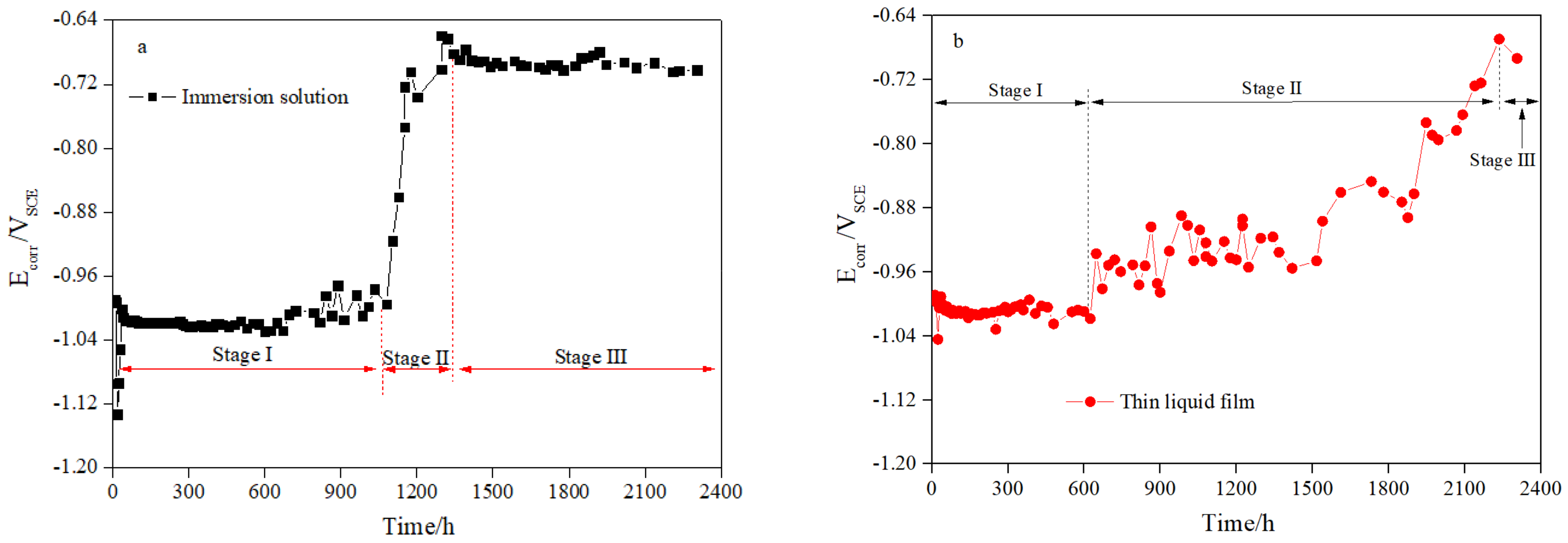
3.3. Open Circuit Potential

The OCP change trends of the WBE with time under immersion and thin liquid film conditions are shown in Figure 6. The OCP of the carbon steel/zinc-rich coating system is the coupling potential of the galvanic cell composed of zinc powder and carbon steel. This showed the area ratio of activated zinc particles to the exposed carbon steel. At a larger area ratio, the coupling potential was closer to the self-corrosion potential of zinc, and the coupling potential was more negative. On the contrary, the coupling potential was closer to the self-corrosion potential of carbon steel, and the coupling potential was more positive [20,34].
According to the cathodic protection standard [35], the protected potential range of carbon steel is −0.78–−1.03 VSCE; if it is higher than −0.78 VSCE, then the carbon steel is unprotected. The change characteristics of self-corrosion potential with time under the immersion and thin liquid film conditions corresponded to the cathodic protection of the current density of the defective area, which can also be divided into three typical stages (Figure 5 and Figure 6). For example, under the immersion condition, in stage I, after 35 h, the current density of the defective area rapidly increased and reached its peak value and OCP decreased by −1.13 VSCE. Then, after 35 h, the current density of cathodic protection gradually decreased and the OCP gradually increased by −0.98 VSCE. At the same time rate, the cathodic protection current density of the defective areas increased, the cathodic polarization degree also increased, and the OCP decreased. However, in stage II, after 1026 h, the cathodic protection current density of the defective areas rapidly increased, and OCP increased. After 1266 h, the anode point reaction occurred and OCP increased by 0.66 VSCE, which is close to the self-corrosion potential of carbon steel and entered stage III.
The OCP change characteristics displayed similar processes under the liquid film condition. In stage I (0–648 h), the OCP decreased by −1.04 VSCE with the increasing cathode current density of the defective areas. Then, the cathodic protection current density decreased, and the OCP increased and remained at −1.00 VSCE. In stage II (648–2231 h), similar to the immersion condition, the change characteristics of OCP were not consistent with that of the cathode current density but slowly increased to −0.67 VSCE with time, and the ER/ZRC lost its effective cathodic protection on the defective areas.
Under the thin liquid film and immersion conditions, the OCP increased to −0.78 VSCE after 2092 and 1152 h, respectively, and entered the unprotection potential state. However, the anode corrosion point occurred in the defective area after 2231–1266 h during the two experiments. Before this time, the OCP values of the two experiments suggested that the metal underneath was in a protected state. Compared with the OCP evaluation method, the detection of cathodic protection current density in the defective areas was more efficient. This phenomenon has also been confirmed in the cathodic protection study of single ZRCs (the zinc powder contents were 75% and 40%) in defective areas [32,33].
The zinc particles in single-layer ZRCs featured no two-stage activation under atmospheric and immersion conditions. Therefore, we speculate that the secondary activation process of zinc particles can correspond to the different permeation paths of electrolyte solution and dissolved oxygen in the composite coatings. The defective coatings displayed two penetration paths of electrolyte solution (including dissolved oxygen). Path 1 is the lateral penetration into the coatings along the defective area, parallel to the coating surface. Path 2 is the longitudinal inward penetration along the coating surface, perpendicular to the coating surface. For the single-layer ZRCs, the two processes could penetrate the coatings and synchronously and simultaneously accelerate the activation of zinc powder in the coatings from different directions, thereby simultaneously generating the cathodic protection current.
For the composite coatings, since the zinc-rich coating was covered with ERs, which insulate against direct contact with the electrolyte solution, the penetration rate of Path 2 was reduced. The rapid activation of zinc powder particles in the first stage was mainly due to the permeation of Path 1. Thus, owing to the complete activation of zinc particles in contact with the electrolyte and dissolved oxygen in Path 1, the cathodic protection current density decreased, and the OCP increased. However, as the electrolyte solution of Path 2 penetrated the epoxy coating and ZRCs, the zinc particles underwent a secondary activation process. Therefore, zinc particles in the composite coatings show significant two-stage independent activation characteristics.
In the secondary activation process of zinc particles, with increasing cathode current density, OCP did not decrease but instead gradually increased, regardless of immersion and atmospheric conditions. Under solution immersion, OCP rapidly shifted to the self-corrosion potential of carbon steel and entered the under-protection state.
The positive shift in OCP indicated the reduction in the area ratio of the activated zinc particles to the exposed substrate. We speculated that because the electrolyte solution penetrates ERCs along Path 2 and penetration through path 1, the substrate will be exposed in a wider range owing to the coating failure process. Because the cathodic current density gradually increased during stage II of zinc particle activation, OCP increased until it entered the under-protection state owing to the gradual reduction in the area ratio of the zinc particles to substrates.

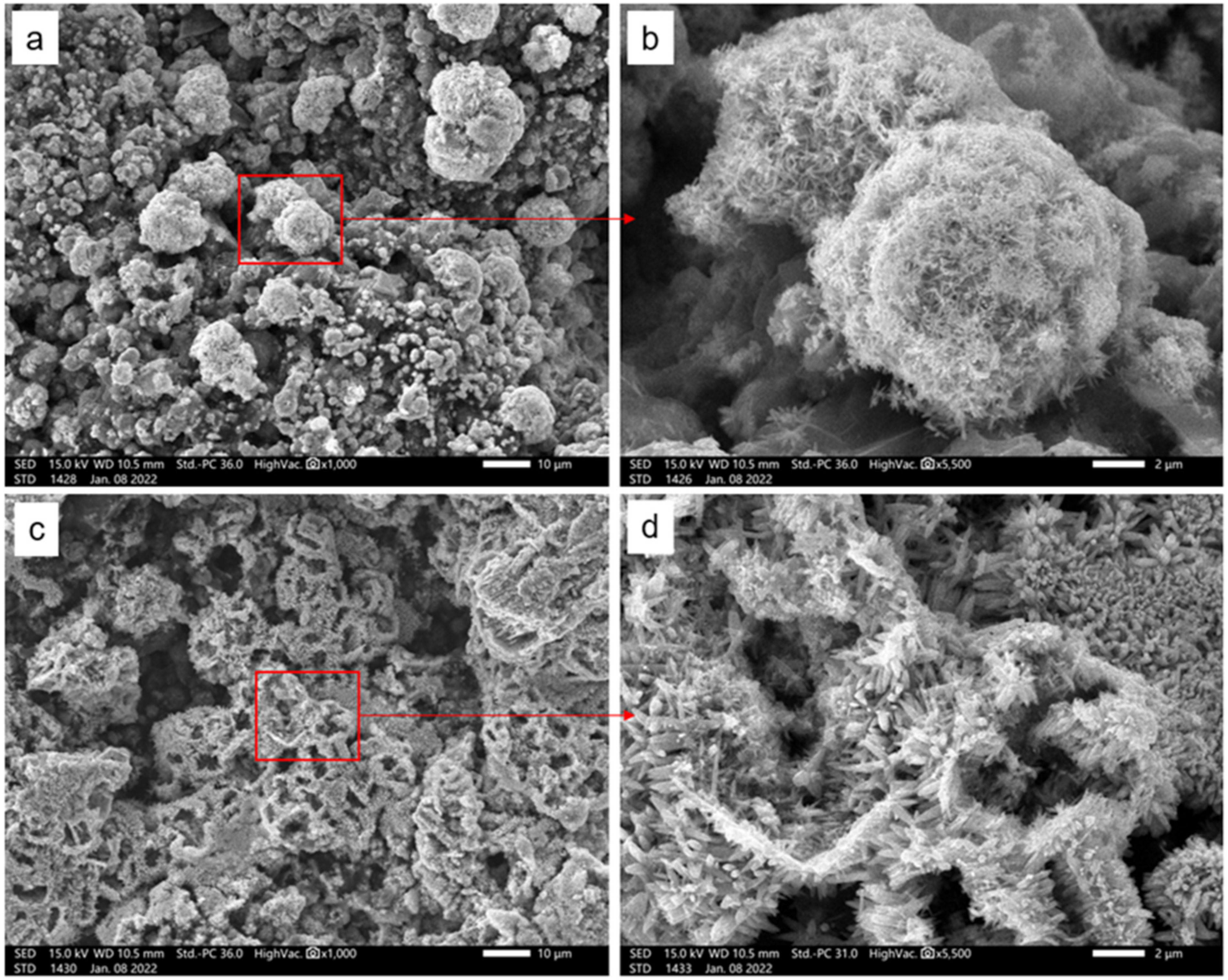
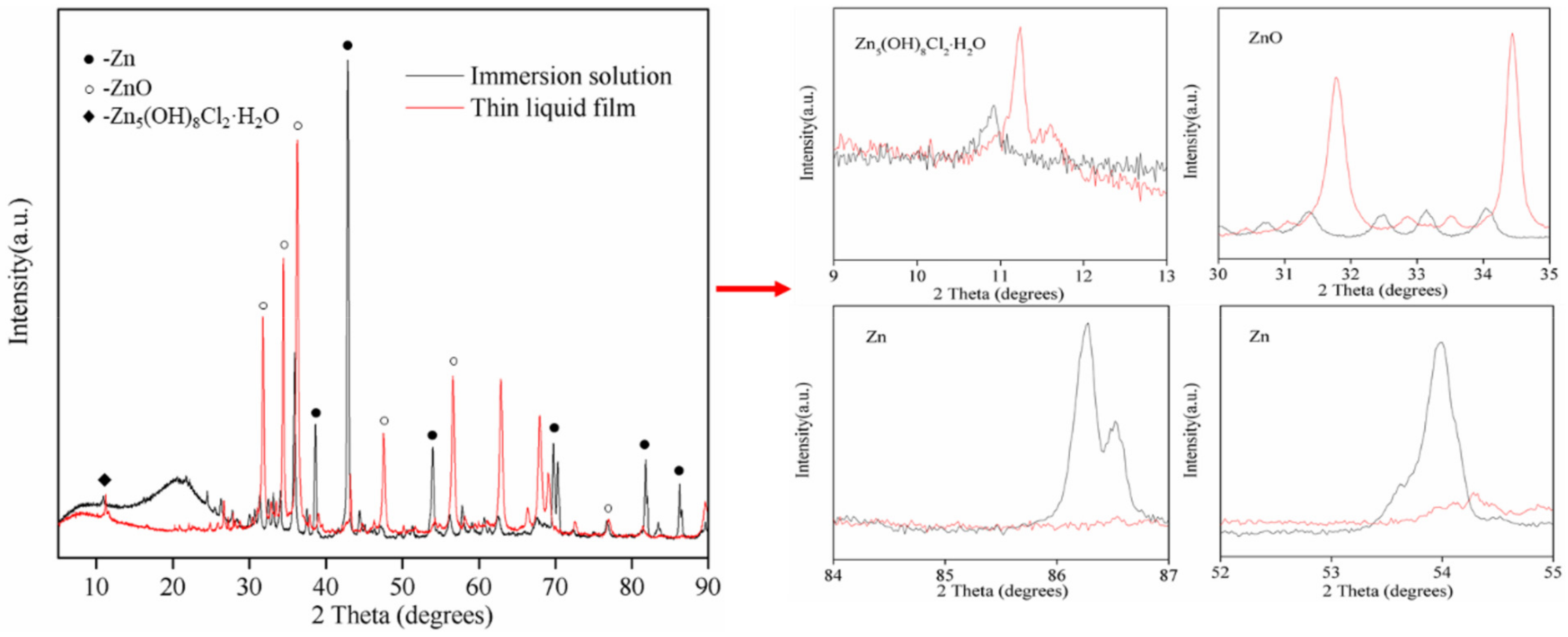
3.4. Surface Morphology and Composition Analysis of Zinc-Rich Coatings

The cathodic protection time of single-layer ZRCs is 60 h in the immersion zone and 180 h in the atmospheric liquid film environment [33]. The cathodic protection time of ER/ZRCs for the defect area is 1314 h in the immersion zone and 2231 h in the atmospheric liquid film environment. The ZRC layer has a similar coating thickness in the defective area. The effective cathodic protection time of single-layer ZRCs under atmospheric and immersion conditions was 180 and 39 h, respectively, which are much lower than that of 2231 and 1314 h in this experiment. The presence of ERs on the surface of ZRCs delayed the rapid activation process of zinc powder by Path 2, which reduces the activation speed of zinc powder and prolongs the protection time [14]. However, the cathodic protection time of the defective area under the atmospheric liquid film was longer than that under the immersion condition.
Under the condition of atmospheric liquid film, porous morphology was observed on the zinc-rich coating (Figure 7c,d), with almost no spherical particles, indicating the serious corrosion of zinc particles. Under the immersion condition, there were obviously spherical zinc particles (Figure 7a,b), which were coated with corrosion products. For single-layer ZRCs, a large amount of electrolyte solution could penetrate the coating from the defective areas (Path 1) and the ZRC surface (Path 2) simultaneously, resulting in the concentrated and rapid activation of zinc powder and the loss of activity. Therefore, the defective area exhibits a shorter protective time. However, because the surface layer was coated with epoxy resin, the electrolyte solution could only permeate the coatings along Path 1, which delayed the permeation coating of Path 2, thereby hindering the concentrated and rapid activation of zinc powder in ZRCs. Therefore, zinc powder particles in the coating can be slowly activated and the protection time can be prolonged. Because the electrolyte penetrated the inner part of ERCs through Path 2, this led to the secondary activation of zinc powder, thereby providing longer cathodic protection. Compared with the immersion condition, the dissolved oxygen content in the zinc-rich coating under the atmospheric liquid film condition was higher [36], and it was easy to replenish after consumption. Therefore, the zinc powder exhibits a higher activation speed, the zinc particle exhibits higher dissolution consumption, and the current density of the cathodic protection time is longer.
The corrosion products of zinc particles are mainly composed of zinc oxide (ZnO) and hydroxyl zinc chloride (Zn5(OH)8Cl2·H2O) [37]. The presence of Zn5(OH)8Cl2·H2 phases is attributed to zinc particle oxidation. The zinc hydroxide formed in Equation (4) further reacts in seawater, and the reaction equation is as follows:
5Zn(OH)2 + H2O + 2Cl → Zn5(OH)8Cl2·H2O(s) + 2OH
Figure 8 shows that the strength of the Zn5(OH)8Cl2·H2O phase and ZnO phase under the liquid film condition is higher than that under the immersion condition, while the strength of the Zn phase under the liquid film condition is lower than that under the immersion condition. The zinc particles were less oxidized under the immersion condition, the zinc particles were consumed seriously under the atmospheric liquid film condition, and a large number of zinc corrosion products were generated.

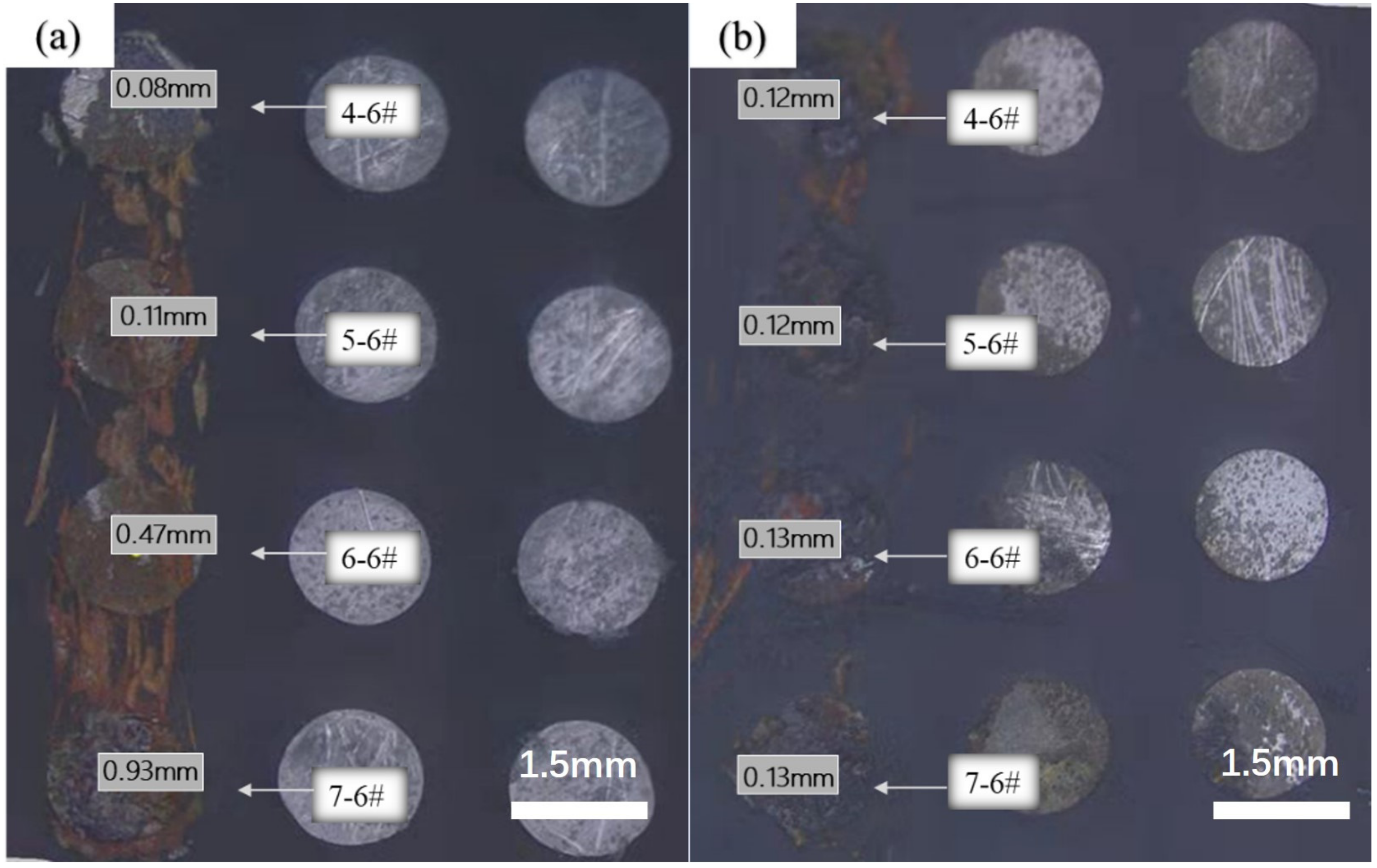
3.5. Surface Corrosion Morphology

Regarding the results after the experiment was conducted, the corrosion morphology near the defective areas on the electrode surface is shown in Figure 9. The corrosion of the base metal was mainly concentrated in the scratches of the defective areas, and the corrosion of the metal under the coating was densely concentrated in other areas. Most electrodes exhibited metallic luster, but only a few electrodes displayed slight corrosion spots.
The minimum corrosion depth of the electrode in the defective solution was 0.08 mm, the maximum corrosion depth was 0.93 mm, and the average corrosion depth was 0.398 mm. However, the minimum corrosion depth of scratches under thin liquid film was 0.12 mm, the maximum corrosion depth was 0.13 mm, and the average corrosion depth was 0.125 mm. The corrosion degree of the base metal in the defective area under the liquid film was lower than that in the defective solution, consistent with the above results of obtaining a stronger cathodic protection current.

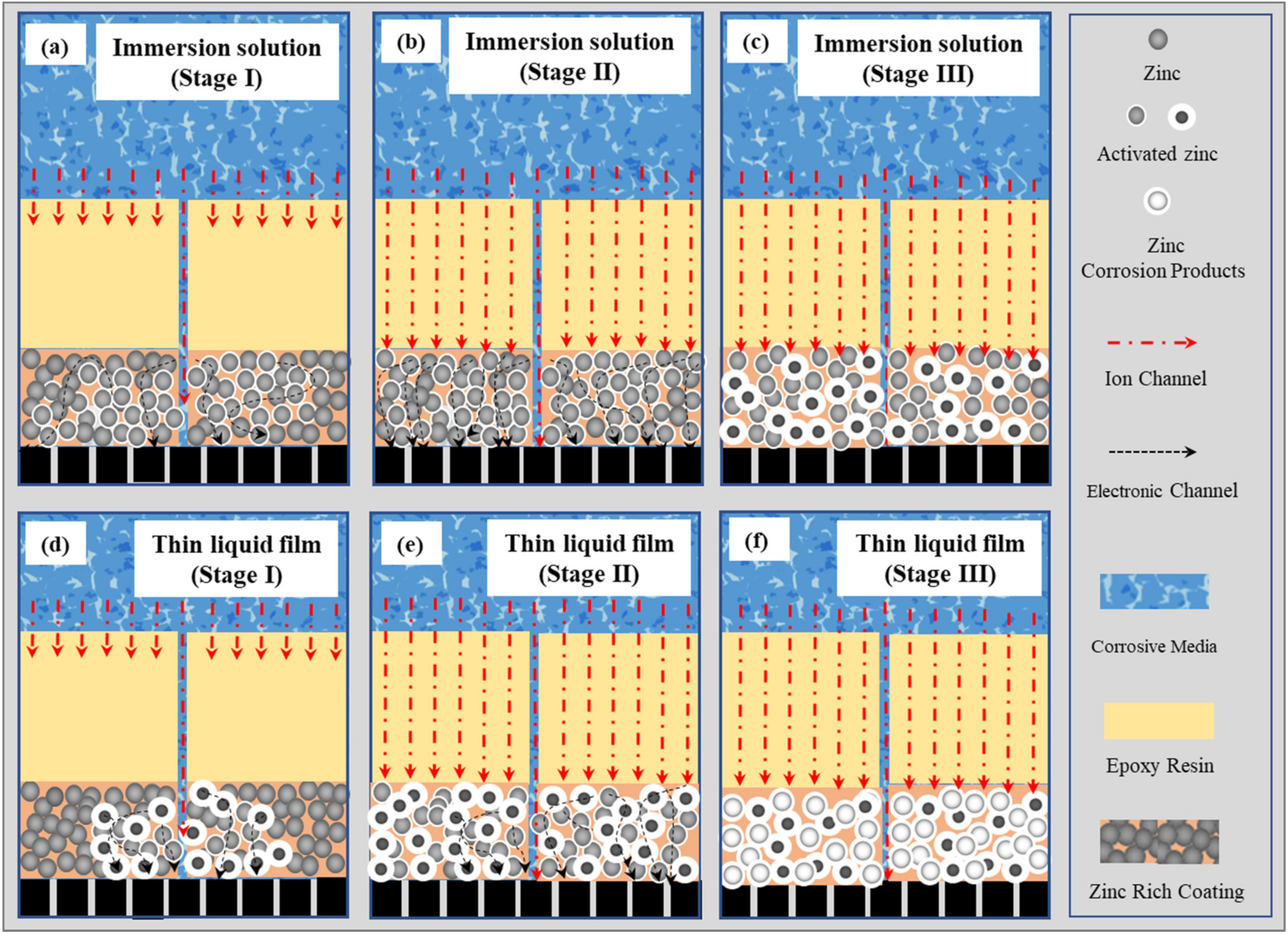
3.6. Mechanism of Zinc Powder Activation and Cathodic Protection

The cathodic protection mechanism of ER/ZRCs on the defective areas under the immersion and atmospheric thin liquid film conditions is shown in Figure 10, where (a)–(c) is under the immersion condition and (d)–(f) is under the atmospheric thin liquid film condition. Since the top coat (ERs) blocked the Path 2 diffusion of the electrolyte solution, the electrolyte solution and dissolved oxygen required for zinc particle activation could only diffuse from the defective areas along Path 1 into the zinc-rich coating (primer), inducing the activation of zinc particles in stage I (Figure 10a,d). The substrate in the defective areas exhibited a strong protection current. The OCP of the WBE rapidly and negatively shifted at the cathodic protection potential interval (Figure 6). Under the atmospheric liquid film condition, owing to the high content and easy supplementation of dissolved oxygen in the electrolyte solution [38,39], the zinc powder in ZRCs exhibited a higher activation degree, providing a higher cathodic protection current density for the substrate in the defective areas (Figure 5).
However, owing to the rapid activation of zinc particles near the defective areas under the atmospheric liquid film condition, a large number of corrosion products were generated to occupy the activation areas, resulting in the removal of electronic channels between zinc particles and the penetration process of electrolyte solution into the zinc-rich coating being hindered. Thus, the activation degree of zinc powder was delayed, and the activation processes in stage I ended quickly (0–648 h).
In stage I of zinc particle activation under the immersion condition, owing to the low concentration of dissolved oxygen, the zinc powder exhibited weak activation (Figure 3). The current density of cathodic protection provided for the defective areas was low (Figure 5) owing to the slow accumulation rate of corrosion products and its limited resistance to the ion and electronic channels of the corrosion cell between the zinc particle and the base metal, thereby prolonging the duration of cathodic protection (0–1026 h).
Because the electrolyte solution penetrated ZCRs along the epoxy coating (Path 2), they underwent activation in the second stage (Figure 10b,e). Compared with stage I, the activation time of stage II was longer (648–2231 h, Figure 6b) under the atmospheric thin liquid film. After entering stage II, the electrolyte solution could enter ZRCs through a wider diffusion path to fully activate the zinc powder particles owing to the blockage of corrosion products in stage I, thereby prolonging the duration of cathodic protection.
Under the immersion condition, the cathodic protection time of stage II was significantly shorter than that of stage I (1026–1266 h, Figure 6a) owing to the low concentration of dissolved oxygen under immersion conditions and difficulty in replenishing the dissolved oxygen. Thus, the activation speed of zinc powder in stage I was slow (Figure 5a), which allowed for sufficient penetration of the electrolyte solution into the zinc-rich coating and the gradual activation of zinc particles (Figure 10b). After entering stage II, a large number of zinc powder particles were activated in stage I; thus, the activation of zinc particles ended rapidly.
Compared with the immersion condition, the dissolved oxygen content in the electrolyte solution under the atmospheric thin liquid film condition was higher and more easily replenished. Therefore, the dissolution consumption of zinc powder particles in the ZRCs is more efficient (Figure 7), providing longer cathodic protection for the defective area.

4. Conclusions

Under atmospheric thin liquid film and immersion conditions, the change characteristics in the cathodic protection current and OCP confirmed that zinc particles in the ER/ZRC system underwent two independent activation processes owing to the corrosive media and dissolved oxygen permeation paths. In the first activation stage, electrolyte solution and dissolved oxygen penetrated the zinc-rich primer along the defective area transversely to induce rapid activation of zinc powder to achieve cathodic protection. As the electrolyte solution penetrated the ZRCs longitudinally along the ERs surface, the zinc particles in the zinc-rich primer were activated in the second stage. Under the immersion condition, the effective cathodic protection time endowed by the activation process of zinc particles in the first and second stages for the defective area was 1026 and 288 h, respectively, and the overall total protection time of zinc particles was 1314 h. However, the duration of the two stages of activation for cathodic protection under the atmospheric liquid film condition was 648 and 1583 h, respectively. The total protection time of the defective area under the atmospheric condition was about 2231 h, which is 1.7 times that under the immersion condition. After the cathodic protection processes, the zinc particles in ZRCs under the atmospheric thin liquid film condition were very few. In contrast, large numbers of undissolved zinc particles were still visible in the coating under the immersion condition. The zinc powder particles in ZRCs exhibited higher cathodic protection efficiency under the atmospheric liquid film condition.

Author Contributions

Conceptualization, W.Z.; Methodology, W.X. and Z.L.; Software, W.Z.; Validation, W.X., G.Z. and Z.L.; Formal analysis, W.X.; Investigation, W.X. and G.Z.; Resources, Z.C.; Data curation, Z.C.; Writing—original draft, W.X. and Z.C.; Writing—review & editing, W.Z. and Z.C.; Visualization, Z.C., G.Z., S.Q. and Z.L.; Supervision, W.Z., S.Q. and Z.L.; Project administration, W.Z.; Funding acquisition, W.Z. All authors have read and agreed to the published version of the manuscript.

Funding

This research was funded by the National Natural Science Foundation of China (Grant Nos. 21203034 and 51771057), the GF Research and Cultivation Project of Sun Yat-sen University (Grant No. 76110-18843406), the National Science and Technology Resources Investigation Program of China (Grant No. 2019FY101400), the Open Research Subject of Zhejiang Key Laboratory of Petrochemical Environmental Pollution Control (Grant No. 2022Z01), and the Zhuhai Industry–University–Research Cooperation Project (Grant No. 2220004002965).

Institutional Review Board Statement

Not applicable.

Informed Consent Statement

Not applicable.

Data Availability Statement

Data are contained within the article.

Conflicts of Interest

Authors Guoqing Zhang and Sicheng Qian were employed by the company Offshore Oil Engineering Co., Ltd. The remaining authors declare that the research was conducted in the absence of any commercial or financial relationships that could be construed as a potential conflict of interest.

References

  1. Yang, F.; Liu, T.; Li, J.; Qiu, S.; Zhao, H. Anticorrosive behavior of a zinc-rich epoxy coating containing sulfonated polyaniline in 3.5% NaCl solution. RSC Adv. 2018, 8, 13237–13247. [Google Scholar] [CrossRef] [PubMed]
  2. Wang, B.; Zhang, L.; Jiang, H.; Li, X.; Mu, X. Atmospheric corrosion comparison of antirust aluminum exposed to industrial and coastal atmospheres. Mater. Corros. 2018, 69, 1516–1525. [Google Scholar] [CrossRef]
  3. Chen, Z.Y.; Persson, D.; Samie, F.; Zakipour, S.; Leygrafb, C. Effect of carbon dioxide on sodium chloride-induced atmospheric corrosion of copper. J. Electrochem. Soc. 2005, 152, 502–511. [Google Scholar] [CrossRef]
  4. Palma, E.; Fernandez, B.; Morcillo, M. Long-term atmospheric cathodic protection of 55% Al-Zn coating on steel and its comparison with galvanized steel. Mater. Corros. 1997, 48, 765–769. [Google Scholar] [CrossRef]
  5. Che, K.; Lyu, P.; Wan, F.; Ma, M. Investigations on Aging Behavior and Mechanism of Polyurea Coating in Marine Atmosphere. Materials 2019, 12, 3636. [Google Scholar] [CrossRef] [PubMed]
  6. Lu, L.; Ma, Z.; Liu, Q.; Zhang, D. Pollutant-accelerated aging behaviors of fluorocarbon coating in tropical marine atmosphere. Prog. Org. Coat. 2020, 139, 105447. [Google Scholar] [CrossRef]
  7. Porter, F.C. Corrosion and electrochemistry of zinc. Br. Corros. J. 1997, 32, 28–29. [Google Scholar] [CrossRef]
  8. Li, H.Y.; Duan, J.Y.; Wei, D.D. Comparison on corrosion behaviour of arc sprayed and zinc-rich coatings. Surf. Coat. Technol. 2013, 235, 259–266. [Google Scholar] [CrossRef]
  9. Ramezanzadeh, B.; Arman, S.Y.; Mehdipour, M. Anticorrosion properties of an epoxy zinc-rich composite coating reinforced with zinc, aluminum, and iron oxide pigments. J. Coat. Technol. Res. 2014, 11, 727–737. [Google Scholar] [CrossRef]
  10. Xing, C.; Wang, W.; Qu, S.; Tang, Y.; Zhao, X.; Zuo, Y. Degradation of zinc-rich epoxy coating in 3.5% NaCl solution and evolution of its EIS parameters. J. Coat. Technol. Res. 2021, 18, 843–860. [Google Scholar] [CrossRef]
  11. Shreepathi, S.; Bajaj, P.; Mallik, B.P. Electrochemical impedance spectroscopy investigations of epoxy zinc rich coatings: Role of Zn content on corrosion protection mechanism. Electrochim. Acta 2010, 55, 5129–5134. [Google Scholar] [CrossRef]
  12. Morcillo, M.; Barajas, R.; Felius, S.; Bastidas, J.M. A SEM study on the galvanic protection of zinc-rich paints. J. Mater. Sci. Technol. 1990, 25, 2441–2446. [Google Scholar] [CrossRef]
  13. LeBozec, N.; Thierry, D.; Persson, D.; Riener, C.K.; Luckeneder, G. Influence of microstructure of zinc-aluminium-magnesium alloy coated steel on the corrosion behavior in outdoor marine atmosphere. Surf. Coat. Technol. 2019, 374, 897–909. [Google Scholar] [CrossRef]
  14. Wang, J.; Qi, Y.; Zhao, X.; Zhang, Z. Electrochemical Investigation of Corrosion Behavior of Epoxy Modified Silicate Zinc-Rich Coatings in 3.5% NaCl Solution. Coatings 2020, 10, 444. [Google Scholar] [CrossRef]
  15. Yan, M.; Gelling, V.J.; Hinderliter, B.R.; Battocchi, D.; Tallman, D.E.; Bierwagen, G.P. SVET method for characterizing anti-corrosion performance of metal-rich coatings. Corros. Sci. 2010, 52, 2636–2642. [Google Scholar] [CrossRef]
  16. Carmona Calero, J.; Climent Llorca, M.A.; Garcés Terradillos, P. Influence of different ways of chloride contamination on the efficiency of cathodic protection applied on structural reinforced concrete elements. J. Electroanal. Chem. 2017, 793, 8–17. [Google Scholar] [CrossRef]
  17. Zhang, L.; Lu, X.; Zuo, Y. The Influence of Cathodic Polarization on Performance of Two Epoxy Coatings on Steel. Int. J. Electrochem. Sci. 2014, 9, 6266–6280. [Google Scholar] [CrossRef]
  18. Lindqvist, S.A.; Meszaros, L.; Svenson, L.J. Aspects of galvanic action of zinc-rich paints. Electrochemical investigation of eight commercial primers. J. Oil Colour Chem. Assoc. 1985, 68, 10–14. [Google Scholar]
  19. Liu, Z.; Wang, W.; Wang, J.; Peng, X.; Wang, Y.; Zhang, P.; Wang, H.; Gao, C. Study of corrosion behavior of carbon steel under seawater film using the wire beam electrode method. Corros. Sci. 2014, 80, 523–527. [Google Scholar] [CrossRef]
  20. Xu, L.; Liu, F.; Liu, M.; Wang, Z.; Qian, Z.; Ke, W.; Han, E.H.; Jie, G.; Wang, J.; Zhu, L. Fabrication of repairable superhydrophobic surface and improved anticorrosion performance based on zinc-rich coating. Prog. Org. Coat. 2019, 137, 105335. [Google Scholar] [CrossRef]
  21. Liao, X.; Cao, F.; Zheng, L.; Liu, W.; Chen, A.; Zhang, J.; Cao, C. Corrosion behaviour of copper under chloride-containing thin electrolyte layer. Corros. Sci. 2011, 53, 3289–3298. [Google Scholar] [CrossRef]
  22. Park, J.H.; Yun, T.H.; Kim, K.Y.; Song, Y.K.; Park, J.M. The improvement of anticorrosion properties of zinc-rich organic coating by incorporating surface-modified zinc particle. Prog. Org. Coat. 2012, 74, 25–35. [Google Scholar] [CrossRef]
  23. Schaefer, K.; Miszczyk, A. Improvement of electrochemical action of zinc-rich paints by addition of nanoparticulate zinc. Corros. Sci. 2013, 66, 380–391. [Google Scholar] [CrossRef]
  24. Liu, X.; Xiong, J.; Lv, Y.; Zuo, Y. Study on corrosion electrochemical behavior of several different coating systems by EIS. Prog. Org. Coat. 2009, 64, 497–503. [Google Scholar] [CrossRef]
  25. Langer, E.; Zubielewicz, M.; Kuczyńska, H.; Królikowska, A.; Komorowski, L. Anticorrosive effectiveness of coatings with reduced content of Zn pigments in comparison with zinc-rich primers. Corros. Eng. Sci. Technol. 2019, 54, 627–635. [Google Scholar] [CrossRef]
  26. Shen, L.; Zhao, W.; Miao, L. Designed a novel EP + GO/ZRC + GO coating with bilayered structure for enhancing corrosion resistance of steel substrate. J. Hazard. Mater. 2021, 403, 123670. [Google Scholar] [CrossRef] [PubMed]
  27. Hussain, A.K.; Seetharamaiah, N.; Pichumani, M.; Chakra, C.S. Research progress in organic zinc rich primer coatings for cathodic protection of metals—A comprehensive review. Prog. Org. Coat. 2021, 153, 106040. [Google Scholar] [CrossRef]
  28. Arianpouya, N.; Shishesaz, M.; Arianpouya, M.M.N. Evaluation of synergistic effect of nanozinc/nanoclay additives on the corrosion performance of zinc-rich polyurethane nano-composite coatings using electrochemical properties and salt spray testing. Waterborne High Solids Coat. Bull. 2013, 34, 13. [Google Scholar]
  29. Akbarinezhad, E.; Ebrahimi, M.; Sharif, F.; Ghanbarzadeh, A. Evaluating protection performance of zinc rich epoxy paints modified with polyaniline and polyaniline-clay nanocomposite. Prog. Org. Coat. 2014, 77, 1299–1308. [Google Scholar] [CrossRef]
  30. Tan, Y.; Liu, T. Inhibiting Localized Corrosion of Aluminum and Aluminum Alloy by Rare Earth Metal Compounds: Behaviors and Characteristics Observed Using an Electrochemically Integrated Multi-Electrode Array. J. Electrochem. Soc. 2013, 160, C147–C158. [Google Scholar] [CrossRef]
  31. Zhong, Q. Study of corrosion behaviour of mild steeland copper in thin film salt solution using thewire beam electrode. Corros. Sci. 2002, 44, 909–916. [Google Scholar] [CrossRef]
  32. Xia, W.; Chen, Z.; Zhang, G.; Zhang, W.; Liu, F.; Yao, C.; Lin, Z.; Li, W. Comparison of cathodic protection processes of 40% zinc-rich coatings under immersion and atmospheric conditions: Protection for defective areas. Electrochim. Acta 2021, 385, 138450. [Google Scholar] [CrossRef]
  33. Xia, W.; Chen, Z.; Zhang, G.; Liu, F.; Lin, Z.; Zhang, W. Cathodic protection of 75% zinc-rich coatings compared under immersion and atmospheric conditions: Protection for defect areas. Corros. Commun. 2021, 4, 12–22. [Google Scholar] [CrossRef]
  34. Cubides, Y.; Castaneda, H.; Savall, C.; Bernard, J.S.T. Corrosion protection mechanisms of carbon nanotube and zinc-rich epoxy primers on carbon steel in simulated concrete pore solutions in the presence of chloride ions. Corros. Sci. 2016, 109, 145–161. [Google Scholar] [CrossRef]
  35. DNV-RP-B401; Cathodic Protection Design. Recommended Practice. DNV GL Group: Høvik, Norway, October 2010.
  36. Gao, M.; Sun, Z.; Yan, W.; Tang, Z.; Zhang, Y. Influence of solid particles deposition on the initial atmospheric corrosion of 7B04 aluminum alloy. Mater. Today Commun. 2022, 31, 103562. [Google Scholar] [CrossRef]
  37. Jalili, M.; Rostami, M.; Ramezanzadeh, B. An investigation of the electrochemical action of the epoxy zinc-rich coatings containing surface modified aluminum nanoparticle. Appl. Surf. Sci. 2015, 328, 95–108. [Google Scholar] [CrossRef]
  38. Li, Z.; Fu, D.; Li, Y.; Wang, G.; Meng, J.; Zhang, D.; Yang, Z.; Ding, G.; Zhao, J. Application of An Electrical Resistance Sensor-Based Automated Corrosion Monitor in the Study of Atmospheric Corrosion. Materials 2019, 12, 1065. [Google Scholar] [CrossRef]
  39. Wang, S.; Yang, J.; Cao, J.; Jiang, S.; Xu, F. Evaluation of increasing service life of epoxy zinc-rich coating on 3 wt.% Ni-advanced low-alloy steel in marine atmospheric environment. J. Iron Steel Res. Int. 2022, 29, 698–706. [Google Scholar] [CrossRef]
Figure 1. Image of the WBE before applying the coating to the surface.
Coatings 14 00336 g001
Figure 2. Cross-sectional SEM images of ER/ZRCs before the experiment.
Coatings 14 00336 g002
Figure 3. Evolution of current density distribution with time under immersion times of (a) 1 h; (b) 24 h; (c) 1314 h; (d) 2400 h.
Coatings 14 00336 g003
Figure 4. Evolution of the current density distribution with time under the atmospheric thin liquid film condition at (a) 1 h; (b) 24 h; (c) 624 h; (d) 2231 h.
Coatings 14 00336 g004
Figure 5. Variation in the cathodic current density in the defective areas under the (a) immersion and (b) thin liquid film conditions.
Coatings 14 00336 g005
Figure 6. Evolution of OCP with immersion time under the (a) immersion and (b) thin liquid film conditions.
Coatings 14 00336 g006
Figure 7. SEM micrographs obtained from the surface of the zinc-rich coating after exposure to 3.5 wt.% NaCl solution for 2400 h. (a,b) are in the immersion condition; (c,d) are in the thin liquid film condition.
Coatings 14 00336 g007
Figure 8. XRD pattern of ZRCs after 2400 h under the immersion and thin liquid film conditions.
Coatings 14 00336 g008
Figure 9. Corrosion morphology of the electrode surface defect area after removing the coating at the end of the experiment under the (a) immersion and (b) atmospheric thin liquid film conditions.
Coatings 14 00336 g009
Figure 10. Schematic representation of the cathodic protection mechanism of ER/ZRCs for the (ac) immersion and (df) thin liquid film conditions.
Coatings 14 00336 g010
Disclaimer/Publisher’s Note: The statements, opinions and data contained in all publications are solely those of the individual author(s) and contributor(s) and not of MDPI and/or the editor(s). MDPI and/or the editor(s) disclaim responsibility for any injury to people or property resulting from any ideas, methods, instructions or products referred to in the content.

