Article

Scratch Response of Hollow Cathode Radiofrequency Plasma-Nitrided and Sintered 316L Austenitic Stainless Steel

by
Marcelo Broch
1,2,
Cristian Padilha Fontoura
1,
Arnaldo Oliveira Lima
3,
Michell Felipe Cano Ordoñez
3,
Izabel Fernanda Machado
3,
Cesar Aguzzoli
1 and
María Cristina Moré Farias
1,*
1
Graduate Program in Materials Science and Engineering, University of Caxias do Sul, UCS, Rua Francisco Getúlio Vargas, 1130, Caxias do Sul 95070-560, RS, Brazil
2
Instituto Federal de Educação Ciência e Tecnologia do Rio Grande do Sul, IFRS, 1730 Avelino Antônio de Souza St, Caxias do Sul 95043-700, RS, Brazil
3
Surface Phenomena Laboratory, Escola Politécnica, University of Sao Paulo, Av. Prof. Mello Moraes, 2231, São Paulo 05508-030, SP, Brazil
*
Author to whom correspondence should be addressed.
Coatings 2024, 14(3), 334; https://doi.org/10.3390/coatings14030334
Submission received: 3 November 2023 / Revised: 4 March 2024 / Accepted: 8 March 2024 / Published: 12 March 2024
(This article belongs to the Special Issue Tribological and Mechanical Properties of Coatings)

Abstract

:
Low-temperature plasma nitriding is a thermochemical surface treatment that promotes surface hardening and wear resistance enhancement without compromising the corrosion resistance of sintered austenitic stainless steels. Hollow cathode radiofrequency (RF) plasma nitriding was conducted to evaluate the influence of the working pressure and nitriding time on the microstructure and thickness of the nitrided layers. A group of samples of sintered 316L austenitic stainless steel were plasma-nitrided at 400 °C for 4 h, varying the working pressure from 160 to 25 Pa, and the other group was treated at the same temperature, varying the nitriding time (2 h and 4 h) while keeping the pressure at 25 Pa. A higher pressure resulted in a thinner, non-homogeneous nitrided layer with an edge effect. Regardless of the nitriding duration, the lowest pressure (25 Pa) promoted the formation of a homogenously nitrided layer composed of nitrogen-expanded austenite that was free of iron or chromium nitride and harder and more scratching-wear-resistant than the soft steel substrate.

1. Introduction

Low-temperature thermochemical treatments have been extensively applied to austenitic stainless steels to improve their surface hardness, fatigue, and wear resistance while maintaining their corrosion performance. This route is a way to expand the range of applications of these materials, which are today dominated by the chemical, petrochemical, pharmaceutical, and food industries [1,2,3,4,5,6,7]. Low-temperature plasma-assisted nitriding and nitrocarburizing are diffusion treatments that minimize the detrimental effects of the generally unwelcome porosity in powder metallurgy (P/M) austenitic stainless steels and iron [8,9,10]. The surface porosity of P/M steels promotes a faster growth of the nitrided layer in comparison with the fully dense steels [10]. Plasma-nitriding processes allow for nitrogen diffusion in the crystal lattice, promoting the formation of a nitrogen-expanded austenite phase (γN) layer [11,12,13,14] and an improvement in the corrosion resistance and mechanical and tribological properties of wrought [13,15,16,17,18,19,20,21] and sintered ASS [22,23,24,25]. In addition, compared with gaseous heat treatment technologies, plasma-assisted treatments show reduced explosion risks and produce insignificant levels of dirt, toxic fumes, noise, and reduced energy consumption [26]. Low-temperature plasma nitriding and nitrocarburizing also prevent the precipitation of hard compounds in the inner surface of interconnected pores, preventing both the embrittlement and the losses in the corrosion resistance of the treated P/M parts [22,27].
The nitriding efficiency can be increased in low-pressure radiofrequency (RF) plasma-nitriding treatments, performed at approximately 0.1 Pa, since the higher mean free path reduces the collision probability between particles and allows for the presence of a large number of active species in the plasma atmosphere. Another significant advantage of low-pressure plasma nitriding over conventional plasma nitriding conducted at higher pressures of 100–1000 Pa is that the discharge is inherently stable and reduces its tendency to transform into an arc [28,29]. This process has been successfully used in nitriding AISI 316 stainless steel, since it allows for performing relatively low-temperature treatments at 400 °C, thereby avoiding chromium migration, chromium nitride precipitation, and corrosion resistance loss [30,31,32,33]. RF plasma nitriding brings additional advantages such as minimal distortion of the treated workpiece, shortening the nitriding time, a slower decrease in nitrided layer thickness, better control of the substrate temperature, and a lower feed gas consumption [28,34].
In conventional DC plasma nitriding systems, the plasma forms directly on the surface of the workpiece, which causes an inhomogeneous temperature and inherent defects, such as arc damage and edging [35]. One of the methods to increase the current density of the plasma is through a hollow cathode discharge (HCD), in which the geometry of the cathode is modified to a hollow structure that encloses the plasma with a higher concentration of high-energy electrons, promoting intense ionization [36]. The higher current density, known as the hollow cathode effect (HCE), is due to the creation of secondary electrons through the interaction of high-energy oscillating electrons or ‘pendulum’ electrons with the cathode sheath. These secondary electrons increase the probability of collisions with other neutral atoms that are present in the plasma, which increases the excitation and ionization efficiency [37,38]. Therefore, the heating efficiency in HCD plasma nitriding can be raised compared to conventional plasma nitriding. This results in an effective treatment of austenitic stainless steels, promoting a uniform single S-phase layer without the CrN precipitation, enhanced hardness, and wear and corrosion resistance [31,32,33,34,39,40,41,42].
Various radiofrequency hollow cathode discharge sources have been employed to deliver high-density plasma for plasma-processing technologies [43,44]. For these systems, the HCE can be generated at low and high pressures, depending on the geometry and cathode material, discharge current, and working gas [38,45]. RF HCD setups can be specially designed to operate at gas pressures that are significantly lower than the commonly used pressures for DC HCD [46]. RF hollow cathodes of a small size can reach a high bias voltage, are relatively easy to install, and can be used to treat selected areas of components, such as hollow substrates and narrow tubes [44,47].
In some practical applications, the contact between surfaces can be characterized by the microscale-to-nanoscale contact. These realistic contact scales open a possibility to evaluate the mechanical and tribological performance of metallic, ceramic, and composite parts, as well as coated surfaces, through instrumented scratch tests at the nano- or microscale. Scratch tests are widely used to assess the mechanical failure modes and adhesion strength of coating–substrate systems at a specific normal load [48,49]. Furthermore, the failure modes and tribological behavior of metallic surfaces that are modified by plasma-assisted treatments such as low-temperature nitriding, carburizing, and nitrocarburizing using scratch tests have also been reported. Yildiz and Alsaran [50] investigated the multi-pass scratch test behavior of a nitrided layer that was formed after plasma nitriding of the AISI 316L austenitic stainless steel. The authors reported a tensile cracks failure mode inside the tracks of the nitrided layers and a variation in the friction coefficient and wear rate at different applied loads. Espitia et al. [51] used the scratch test to investigate the friction coefficient’s behavior, failure mode, and critical load to damage the expanded martensite layer formed on the active screen-plasma-nitrided AISI 410 martensitic stainless steel. The authors found tensile cracking to be the mechanical failure mode and a decrease in the friction coefficient after plasma nitriding. Progressive and multi-pass scratch tests conducted by Manfrinato et al. [52] in plasma-nitrided and nitrocarburized AISI 321 austenitic stainless steel revealed that increasing the treatment temperature produces a detrimental effect concerning failure mechanisms and higher values of the friction coefficient and wear volume.
The novelty of this research work lies in applying the RF HCD plasma source to nitride the powder metallurgy 316L austenitic stainless steel. To our knowledge, such processes have not been performed concomitantly in plasma nitriding of this high-alloy steel family in its sintered state. In addition to the advantages of plasma nitriding of sintered parts over conventional gas and salt bath surface treatments [27], specific considerations have motivated the investigation into the RF HCD of the sintered 316L steel. For instance, the RF plasma source enables low-temperature nitriding treatments, so that the corrosion resistance is not compromised by the precipitation of chromium nitride on the nitrided layer and pores.
With this background, this work investigated the scratch response of a sintered grade 316L austenitic stainless steel after hollow cathode plasma-nitriding (HCPN) treatment with a radiofrequency (RF) power source. Thus, a uniform nitrided layer is expected through a hollow cathode discharge and a radiofrequency power source for plasma nitriding of the sintered 316L steel, depending on the working pressure. The scratched surfaces were characterized using field emission scanning electron microscopy and 3D optical profilometry. The relationships among the scratching wear behavior, hardness, elastic modulus, and the indentation energy of nitrided layers were analyzed.

2. Materials and Methods

2.1. Material Processing

In this work, we conducted treatments on AISI 316L austenitic stainless steel samples manufactured by conventional powder metallurgy (P/M), as described elsewhere [25]. The materials were P/M-processed from 61,6 μm (d50-equivalent particle diameter) water-atomized AISI 316L steel (Höganäs, Tomball, TX, USA), with a chemical composition of 0.025% C, 0.81% Si, 0.13% Mn, 16.8% Cr, 12.8% Ni, 2.20% Mo, and bal. Fe (in wt. %). The steel powders and 1 wt % of Licowax® binder were mixed with a V-type mixer and then uniaxially compacted to 400 MPa. After the debinding step (350 °C, 2 h, air atmosphere), the samples were sintered for 30 min in an argon atmosphere at 1280 °C, at a rate of 10 °C min−1, and then slowly cooled down to room temperature inside the furnace.
The sintered samples were mechanically polished to a 1000-grit sandpaper finish, ultrasonically cleaned in a pure acetone bath for 10 min, and finally dried in a stream of air. The sintered samples were treated by radiofrequency (RF) plasma nitriding with a hollow cathode discharge (HCD). A detailed setup of the reactor that was used in the RF HCD PN treatments is described elsewhere [53]. A gas mixture of 75% N2 + 25% H2 in volume was admitted into the chamber until reaching the working pressure. The plasma was generated by an RF power source (13.56 MHz), brand Tokyo Hy-Power, model RF-300. The treatment temperature was increased to 400 °C and read with an infrared thermometer. The RF HCD PN treatments were conducted at working pressures ranging from 25 to 160 Pa for 4 h. To evaluate the effect of the nitriding time on the scratch test response, the samples obtained at 25 Pa were nitrided for 2 h and 4 h.

2.2. Characterization of Nitrided Samples

The microstructure of untreated and nitrided samples was examined by optical microscopy and field emission scanning electron microscopy (FESEM, MIRA3, Tescan, Brno, Czech Republic). The thickness of the nitrided layer was determined by FESEM analysis of the cross-section of the treated samples. For this purpose, cross-sectional samples were prepared following the conventional metallographic procedure, consisting of sequential steps of sectioning, mounting, mechanical grinding and polishing, and chemical etching. Sectioning was conducted using a precision cutter and a diamond wafering blade. A thermosetting phenolic resin (Bakelite) was used to mount the samples in compression mounting equipment. The mounted samples were ground in semi-automatic grinding and polishing equipment using 400-, 600-, and then 1000-grid water-cooled silicon carbide (SiC) papers. After grinding, the samples were roughly polished using 6 μm and 3 μm diamond pastes on napless cloths. The final polishing was conducted with a colloidal silica suspension with a particle size of 0.25 μm. After each polishing step, samples were ultrasonically cleaned with acetone for 10 min. Chemical etching was conducted by immersion in Kalling’s reagent.
Phases that formed in the nitrided region were identified by X-ray diffraction (XRD) using a Bruker D8 Advance diffractometer with Cu-Kα radiation (λ = 0.15418 nm), with Bragg–Brentano geometry (θ–2θ), at 40 kV and 30 mA, with an angular range from 35° to 55° (2θ), step size of 0.05°, and 5 s of integration time. XRD patterns were indexed using the X’Pert High Score Plus software (version 2.1) and the Powder Diffraction File (PDF) database of the International Centre for Diffraction Data (ICDD).
The surface hardness of each nitrided layer was determined from the instrumented indentation test (nanoindentation) using a Hysitron T1950 triboindenter equipped with a Berkovich diamond tip and a scanning probe microscope (SPM). Twenty-one measurements were conducted in a (10 × 10) μm SPM image of a sample region with a peak load of 1 mN. The average values of the instrumented hardness were estimated from load–displacement curves, according to the Oliver and Pharr method [54]. Figure 1 shows a schematic representation of the indentation load (P) versus displacement (h) curve, acquired during one complete cycle of loading and unloading in the nanoindentation test of an elastoplastic material. Important quantities are also shown, including the peak load (Pmax), the maximum depth (hmax), the final or residual depth after completing the unloading stage (hr), and the elastic, plastic, and total works of indentation (We, Wp and Wt). The area under the loading curve is defined as the total work (Wt) during indentation of the material up to the maximum load; the area under the unloading curve is defined as the reversible elastic work or elastic recovery (We).; and the area between the loading and unloading curves is defined as the residual plastic work or irreversibly dissipated work (Wp = WtWe).
The surface roughness of the untreated and nitrided surfaces was evaluated with 3D optical profiling with a Bruker Contour GT-K 3D optical profilometer. Ten measurements were taken at distinct locations of each sample. The 3D amplitude and height distribution parameters Sa, Sq, Sz, Ssk, and Sku and the material ratio parameters Sk, Spk, and Svk were selected to assess the surface roughness changes. The arithmetic average (Sa) of the magnitude of the deviation of the profile from the mean plane and the root mean square (Sq) value of the surface departures within a sampling area are among the most utilized parameters in engineering applications. They are considered control parameters to identify process changes but give no information related to the shape or spacing of the surface irregularities. The maximum height of the surface Sz represents the average value of the absolute height of the five highest peaks and the depth of the five deepest valleys (ten-point height of a surface) within a sampling area. Ssk and Sku are the skewness and kurtosis of 3D surface texture, respectively. Ssk represents the degree of symmetry of the surface heights regarding the mean plane and describes the shape of the surface height distribution. This parameter correlates with the load-carrying ability and porosity. Sku provides a measure of the sharpness or spikiness of the area and characterizes the spread of the surface height distribution. The ISO standard 23519 recommends using Sk, Spk, and Svk to characterize the roughness of sintered materials. These functional parameters indicate the ratio of the bearing area to the total surface evaluation area and are essential from a tribological standpoint. The core roughness depth Sk represents the depth of the roughness core profile. The surface peak height Spk is the average height of the highest peaks above the roughness core profile, while Svk, the reduced valley height, is the corresponding average valley depth [55,56,57,58].
The scratch resistance of the nitrided surfaces was evaluated using a Universal Materials Tester (UMT), UMT Tribolab (Bruker, Billerica, MA, USA), with a 5 μm tip radius sphere-conical diamond stylus. The scratch tests were conducted in progressive and constant load modes, with a peak load ranging from 100 to 500 mN over a length of 500 μm with a speed of 4 μm s−1. The normal load, friction force, and scratch depth were sensed during scratching and recorded by the depth-sensing system of the tester. The scratch test failure modes were determined by post facto microscope examination using optical microscopy and FESEM. The scratch wear volume was estimated using a Contour GT-K 3D optical profilometer (Bruker, Billerica, MA, USA).

3. Results and Discussion

3.1. Microstructure and Crystalline Phases of Nitrided Layers

Figure 2 shows FESEM images of the nitrided layers with different treatment pressures. Samples nitrided at higher pressures (160 and 100 Pa) exhibited a light gray peripherical region (border), an intermediate region with shades of blue and brown containing a very thin region in a dark color, and a dark yellow central region (center); see the insert in Figure 2c,d. This phenomenon is known as the edge effect, which produces non-uniform nitrided surfaces following the sample shape and is expected in the treatment of high-alloy materials, such as AISI 316L austenitic stainless steel [59,60,61]. As shown in Figure 2a,c,e,g, the border region of the surface shows the peculiar morphology that is a result of the plasma etching during nitriding with relief at grain boundaries, deformation slip, and twins inside some grains. These surface features are more evident in the central region as the pressure decreases (Figure 2b,d,f,h). The etched appearance of the surface was enhanced, because the sputtering rate increased as the treatment pressure decreased. The lower-pressure plasma generated by RF that diffuses throughout the treatment chamber contains many active species, i.e., nitrogen atoms and ions, and radicals such as NH, that increase the nitriding efficiency. Pressure plays an essential role in influencing the ionization of the plasma in the hollow cathode discharge. In this process, the working pressure depends on the concentration and the pressure of the N2 + H2 gas mixture within the reactor atmosphere. At low pressures, the large mean free path enables the electrons to gain a significant amount of energy imposed by the electric field. This energy is used in collisions with various particles that are present in the plasma such as excited nitrogen molecules (N2*), ionized nitrogen molecules (N2+), NH-radicals, and nitrogen molecules [62].
Uniform nitrided surfaces with similar features (Figure 2e–h) were obtained at lower pressures (50 Pa and 25 Pa), as was also observed in our previous work [25] and by other researchers [2,63,64]. The high stresses that occur during the formation of the nitrided layer promote plastic deformation that causes the formation of the slip steps, grain boundary relief, and twining. These features manifested predominantly along the border regions under higher pressures (Figure 2a,c) and extended across the entire surface under lower pressures (Figure 2e–h). Intrinsic pores from the sintering process can also be seen on the modified surfaces.
Figure 3 shows the X-ray diffraction patterns for samples that were nitrided for 4 h at pressures ranging from 160 to 25 Pa and for a sample that was nitrided for 2 h at 25 Pa. The XRD patterns of the untreated sample are also included. The peaks at (111) and (200) of the austenite γ phase (JCPD 00-033-0397) with a face-centered cubic (fcc) crystalline structure and lattice parameter (a) of 0.355 nm were identified. Additional leveled peaks γN were identified and associated with a nitrogen-rich phase, called the S-phase or expanded austenite. This phase possesses a higher lattice parameter (a111 = 0.381 nm and a200 = 0.386), a consequence of the lattice distortion that is induced by the introduction of nitrogen in different concentrations within the interstitial sites of the cubic structure. The lattice parameter depends on the crystallographic orientation, due to the crystallographic anisotropy of the interstitial nitrogen. One explanation for this phenomenon is the formation of stacking faults and high compressive residual stresses in the nitrided layer, which produces an fcc crystal lattice with significant disorder and distortion [65].
The γN peaks were not observed in the XRD patterns of samples that were treated at the higher nitriding pressure (160 Pa and 100 Pa). Expanded austenite was only observed for the nitrided samples that were treated under 25 Pa and 50 Pa lower pressures. This result can be attributed to the substantial impacts of the high concentration of interstitial nitrogen, which leads to increased distortion of the crystalline lattice and the formation of expanded austenite. Significant distortion of the crystal lattice can lead to a modification of the crystal structure to a triclinic cell with positions that are equivalent to the fcc cubic structure [25]. For 50 Pa and 25 Pa, the γN peaks are broader, grow in area, and shift to lower Bragg angles as the treatment pressures decrease. The shift in peak positions of the X-ray pattern is ascribed to lattice expansion associated with stacking faults and high compressive residual stresses in expanded austenite related to a high nitrogen content. According to an analysis conducted by Sun, Li, and Bell, the stacking faults cause the shifting of the (200) peak to lower angles, while the (111) peak is shifted to higher angles. Compressive residual stresses cause shifting of austenite diffraction peaks to lower angles [66].
Further analysis of the XRD patterns revealed that low-temperature (400 °C) plasma-nitriding treatments inhibited the precipitation of chromium nitrides in the modified layer of the sintered 316L steel. The 2θ positions at 37.60° (111) and 43.69° (200) of the cubic halite-type CrN (JCPD 01-076-2494), the two orientations of greater intensity, as well as the position of highest intensity at 43.17° 1   1 ¯   1 ¯ of the trigonal Cr2N (JCPD 00-001-1232), did not coincide with any of the observed positions of the XRD patterns of the nitrided samples that are shown in Figure 3.

3.2. Thickness of Nitrided Layers

Figure 4 shows the cross-section micrographs of the nitrided layers. The nitrided layer seems to be unetched by the chemical reagent. It appears as a single layer, separated from the substrate by an etched line, as the typical nitrogen-expanded austenite layer of austenitic stainless steels does [25,67]. The thickness of the modified layer was almost the same for 160 Pa and 100 Pa but increased from an average value of 1.85 μm to 4.08 μm as the pressure decreased up to 25 Pa (Table 1). Plasma nitriding using a hollow cathode configuration allows for greater confinement of energetic electrons and ions, enabling heating of the sample in the cavity using a lower potential [68]. The enhanced nitriding efficiency with the decrease in treatment pressures is associated with the diffusion of a higher nitrogen content from the surface to the substrate, which increases the thickness of the modified layer [33]. The nitrogen diffusion also increased with treatment time, resulting in the layer at 25 Pa and 4 h (4.08 μm) being thicker than the one at 25 Pa and 2 h (2.25 μm). In the SEM images in Figure 4, the precipitation of chromium nitride phases in the form of dark gray regions within the layer is not observed, contrasting with the findings in plasma-nitrided layers obtained at temperatures higher than 500 °C [35,41]. Furthermore, slip lines are observable within the nitrided layer, formed due to the plastic deformation that was induced during the plasma-nitriding treatment [11].
Given the higher homogeneity (no edge effect, Figure 2e–h) of the nitrided layers that were obtained through low-pressure treatments, the following results (hardness, surface roughness, and scratch behavior) will be presented considering the nitriding treatments conducted at a pressure of 25 Pa and nitriding time of 4 h and 2 h.

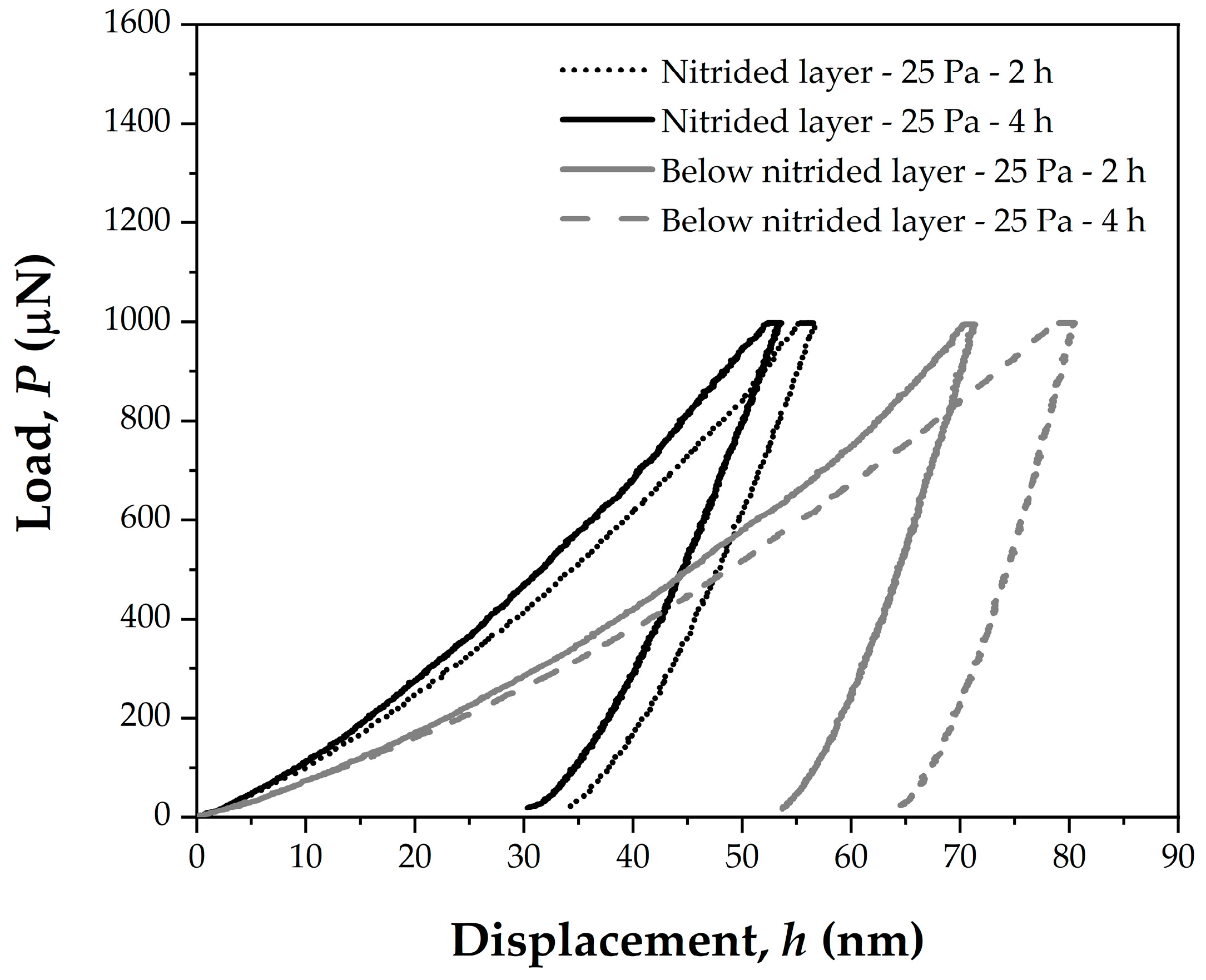
3.3. Hardness of Nitrided Layers

Figure 5 shows the load–displacement curves that were obtained during nanoindentation tests in a region located on the nitrided layer (NL) and the base steel (below the nitrided layer, BNL). The hardness (H), the ratio of the residual depth to maximum depth (hr/hmax), the ratio of the irreversible plastic work to total work (Wp/Wt), the ratio of the reversible elastic work to total work (We/Wt), and the ratio of the hardness to elastic modulus (H/E) for the two regions are given in Table 2. We/Wt quantifies the predominance of reversible deformation (elastic deformation) over irreversible deformation (plastic deformation). The H/E ratio, termed ‘elastic strain to failure’, is often employed as an index of the wear resistance of bulk materials and coatings. A higher H/E ratio indicates better wear resistance [69,70,71,72]. This dependence is grounded in the premise that materials with higher H/E ratios tend to absorb more elastic energy and, therefore, undergo reduced damage. There are close-to-linear or non-linear relationships between the ratio of We/Wt or Wp/Wt and the ratio of hardness to the reduced modulus (H/Er), depending on the material and indenter angle. The ratio of hr/hmax is equivalent to that of Wp/Wt [73,74,75,76]. By knowing the Poisson’s ratio of the sample and indenter and the Young’s modulus of the indenter, Young’s modulus of the sample (E) can be obtained, enabling the calculation of H/E [54].
No significant change in elastoplastic deformation (hmax) and permanent deformation (hr) of the nitrided layer occurred with the increase in nitriding duration from 2 h to 4 h (Figure 5). The same trend was observed for the hr/hmax, Wp/Wt, We/Wt, and H/E ratios (Table 2). These results suggest that a shorter RF HCD plasma-nitriding treatment can yield improved mechanical and tribological properties, comparable to those of longer treatments.
The lower deformation that is undergone by the nitrided layer (Figure 5) explains the increased surface hardness of the samples after nitriding (Table 2) compared with regions below the nitrided layer. Nevertheless, the nitriding treatment markedly improved the mechanical behavior of the sintered AISI 316L steel, for which an average surface hardness of 9.1 GPa was achieved at 25 Pa for 2 h and 4 h, against the 1.2 GPa of the untreated material.

3.4. Surface Roughness

Figure 6 shows the measured 3D surface amplitude and material ratio parameters. The Sa and Sq parameters represent an overall measure of the surface texture. Sz characterizes the maximum peak-to-valley magnitude for the entire surface. A positive skewness value indicates a surface with a preponderance of peaks, while a negative value suggests a predominance of valleys in the surface profile. If the surface comprises many high peaks and low valleys, Sku > 3; otherwise, Sku < 3 (few high peaks and low valleys). Sk (core roughness depth) determines the wear resistance of the surface in a steady-state regime, Spk (reduced peak height) represents the amount that is worn down in the running-in state, and Svk (reduced valley depth) provides information on the lubricant retention and debris-trapping capability of the surface [56].
From the evaluation of the roughness parameters shown in Figure 6, it is clear that the RF HCD plasma nitriding generated a rougher surface layer when compared to the polished untreated surface, as all the measured roughness parameters exhibited higher values. The variations in the values of roughness parameters with the increase in nitriding time were not significant, considering the measurement uncertainties. However, considering only the average values of all the roughness parameters, they tended to be higher with an increasing nitriding duration. The skewness Ssk values shown in Figure 6b were negative (Ssk < 0), which means that depressions or deep valleys predominated on the untreated and nitrided surfaces. The average value Ssk tended to be more negative, which suggests a slight increase in the number of deep valleys after nitriding and for a more prolonged treatment. Figure 6b shows that the kurtosis Sku exceeded 3, indicating a large number of high peaks and low valleys on the surface before and after nitriding. Mainly, this roughness parameter exhibited a strong sensitivity to the increase in nitriding time, showing a notable rise from 23.45 to 107.84 (3.8 times higher). The increased surface roughness that was observed after plasma nitriding can be attributed to the ion bombardment that is induced by the plasma nitriding process. This phenomenon outlined the characteristic austenitic microstructure featuring typical grain boundary reliefs resulting from plastic deformation, as shown in Figure 2. Previous studies have shown that increasing the temperature and time or reducing the pressure of plasma-nitriding treatments intensifies these nitrided surface features [63,77], reflecting the increase in surface roughness [78], as seen in Figure 6, for the more prolonged treatment. The negative value of Ssk (−1.74) for the untreated polished surface of the sintered sample can be ascribed to the residual pores, resulting from the conventional powder metallurgy process. Following nitriding, there was an increase in Ssk to −6.67. This shift towards more negative values is linked to the sealing surface porosity effect [8], which is believed to be a consequence of the grains uplifting from the plastic deformation during plasma nitriding. The sealing effect has been reported to improve the surface properties of sintered parts [79,80], which is assumed to apply in the present work, as evidenced by the enhanced hardness and scratching wear resistance of the nitrided samples.

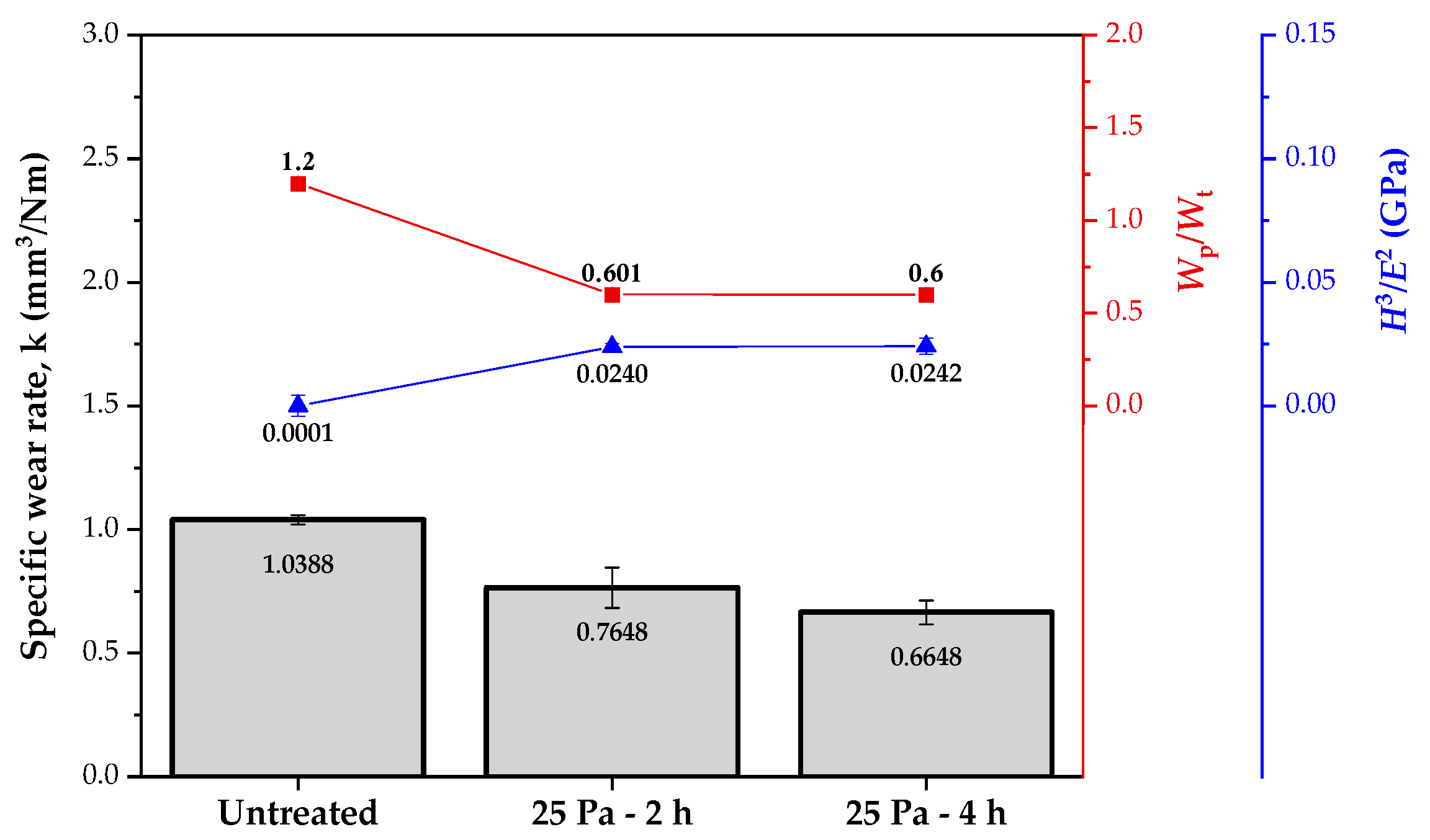
3.5. Scratch Characterization

Figure 7 shows the optical microscopy images of the scratch tracks on the substrate (untreated steel) and the nitrided layer from the progressive load scratch tests, with a normal load ranging from 100 to 500 mN. As in the optical images, the FESEM micrographs (Figure 8b) of the scratch tracks show the brittleness of the nitrided layers, which is attributed to their high hardness. A detailed examination of Figure 7 and Figure 8 indicated that mixed damage modes occurred, related to the brittleness and roughness of the modified surface and ductility and porosity of the sintered substrate. These features may influence the stylus contact area during the scratch tests of the material and, hence, the type of surface damage [81,82]. For the scratch test at 100 mN, almost no cracks were observed, while for the higher applied loads, cracks propagated in a perpendicular direction to the scratching movement. The distance between cracks seems to increase as the applied load is increased. Ductile tensile cracks and spallation can be observed.
Table 3 indicates an increase in the scratch track width with the normal load for the constant load scratch tests, which suggests a corresponding rise in volume loss. The extension of the duration of plasma nitriding did not result in a significant change in the width and depth of the scratch track. For the two-hour plasma-nitriding treatment, the depth of the scratch track that was obtained at a load of 300 mN (2.35 μm) surpassed the thickness of the nitrided layer (2.25 μm), as shown in Table 1. Thus, the scratch test stylus reached the stainless steel substrate at a normal load that was higher than 300 mN. Conversely, for the four-hour treatment, the depth of the scratch tracks did not exceed the thickness of the nitrided layer (4.08 μm), even when subjected to the highest scratch normal load of 500 mN (3.19 μm of scratch track depth).
Examining the correlation between the scratch depth and nitrided layer thickness helps to understand the scratch test severity and the substrate effect on the scratch failure modes, friction, and wear responses of the nitrided samples. The observed tensile cracks on the scratch tracks of the nitrided samples occur in brittle coatings on ductile substrates. These coating–substrate systems can be treated as a hard nitrided and modified layer that diffuses into a ductile substrate [48,83]. The tensile crack failure mode involves the plastic deformation of the ductile 316L stainless steel substrate, a characteristic that is highlighted by its higher hr/hmax ratio of 0.74 against the 0.58 of the nitrided layer (Table 2).
Figure 9 shows the average friction coefficient obtained from the instrumented scratch tests in constant load mode. The friction coefficient became higher as the normal load increased for all the samples. The sample treated for the longest time (4 h) showed an average friction coefficient that was lower than the other samples, and this trend was more pronounced as the normal load was increased. As the scratch test stylus reached the substrate, the friction coefficient values observed in Figure 9 for the untreated and two-hour treated samples tested at 200 mN, 300 mN, and 500 mN normal loads are comparable. The lower values of friction coefficient of the four-hour sample carry a smaller substrate effect.
The values of the specific wear rate are shown in Figure 10. This term represents the volume of material loss by scratching wear per unit of normal load per unit of sliding distance. The values of the Wp/Wt and H3/H2 ratios of the samples are also shown in Figure 10. The H3/E2 ratio indicates the resistance to plastic deformation that is also used to describe and rank the wear resistance of layers and coatings [79,84].
The scratching wear response of the nitrided samples was similar under the more severe normal load (500 mN), considering the measurement uncertainties. However, regarding the nitriding conditions, the untreated sample underwent marked scratching wear. The untreated sample showed the highest irreversible dissipated energy (Wp/Wt) and, hence, the highest wear. This relationship suggests that the RF HCD plasma-nitriding treatment of the austenitic stainless steel produced an enhanced surface performance concerning deformation energy that gave rise to a more wear-resistant material. Additionally, as pointed out by other studies, the material response in terms of the deformation energy estimated from instrumented indentation can be considered a valuable predictor of the scratch wear behavior of materials with surfaces that have been modified by low-temperature plasma nitriding [51]. The similar values of the Wp/Wt ratio, regardless of the duration of the plasma-nitriding treatment, elucidate the comparable scratch wear rate of the samples that were nitrided for 2 h and 4 h. This pattern holds when examining the relationship between the H3/E2 ratio and the wear rate, as can be seen in Figure 10. Comparing only the average values of the specific wear rate between the two nitrided samples (25 Pa; 2 h and 4 h), a slight decrease was noted (from 0.7648 to 0.6648 mm3/Nm). This trend can be related to the surface strain hardening of the nitrided layer that was produced by the increased concentration of interstitial nitrogen during the more prolonged treatment [25,77]. Nevertheless, the strain hardening that was induced by the interstitial solid solution did not change the overall plastic work (Wp/Wt), elastic strain to failure (H/E), and resistance to plastic deformation (H3/E2) of the two nitrided layers.
The quantitative scratch wear response is linked with the surface roughness values that are depicted in Figure 6. Early studies have confirmed a correlation between roughness parameters and friction and wear responses under various contact conditions [82,85,86,87]. The skewness Ssk and kurtosis Sku have been identified as tribologically significant. In the present study, the lowest average specific wear rate of the four-hour nitrided sample was achieved for the minimum values of the Ssk parameter and the maximum values of the Sku parameter. Similar trends were observed previously [85]. Furthermore, one can see that the increased average values of the Sk, Skp, and Skv parameters corresponded to a decrease in the average wear rate. This implies that performing nitriding and longer nitriding treatment enhanced the scratch wear resistance of the sintered 316L stainless steel during the running and steady-state stages.

4. Conclusions

Plasma nitriding using a hollow radiofrequency cathode has proven to be an effective route to improve the mechanical behavior and scratch wear resistance of sintered 316L stainless steel. The use of the hollow cathode increases the ionization efficiency under low pressure and low temperature conditions (25 Pa; 400 °C), resulting in the formation of a homogeneous layer of expanded austenite without chromium nitride precipitation. At the highest pressures, 100 and 160 Pa, a non-uniform plasma promotes the occurrence of the edge effect, causing the formation of a non-homogeneous nitrided surface. Regarding the effect of the nitriding duration for the treatment conducted at the lowest pressure of 25 Pa, an extended treatment of 4 h results in a rougher nitrided surface. This trend is attributed to the intensified plasma ion bombardment during the prolonged treatment. The reduction in the friction coefficient and the improved scratch wear resistance of the sample that was nitrided at 25 Pa and 4 h are mainly related to the effect of the augmented thickness of the expanded austenite layer. This enhancement in micro-scratching behavior allows for higher load support and a more elastic work response than those of the sample that was nitrided for a shorter time of 2 h and the soft steel substrate.

Author Contributions

Conceptualization, M.B., M.F.C.O. and M.C.M.F.; Formal analysis, M.B., C.P.F. and A.O.L.; Investigation, M.B., C.P.F. and A.O.L.; Methodology, M.B., M.F.C.O., C.A. and M.C.M.F.; Project administration, M.C.M.F.; Supervision, M.C.M.F.; Writing—original draft, M.B., M.F.C.O., I.F.M., C.A. and M.C.M.F.; Writing—review and editing, M.B., M.F.C.O. and M.C.M.F. All authors have read and agreed to the published version of the manuscript.

Funding

This research received financial support from the Coordination for the Improvement of Higher Education Personnel (CAPES) through the Master’s Program scholarship CAPES-PROSUC granted to M.B. (Grant 88887.338544/2019-00). Additionally, funding was provided by the National Council for Scientific and Technological Development (CNPq) through the Productivity Research PQ2 scholarships granted to M.C.M.F. (Grant 313156/2022-0), I.F.M. (Grant 305343/2022-0), and C.A. (Grant 304602/2022-1).

Institutional Review Board Statement

Not applicable.

Informed Consent Statement

Not applicable.

Data Availability Statement

The data presented in this study are available on request from the corresponding author.

Acknowledgments

The authors would also like to thank Laboratório Central de Microscopia—LCMIC from UCS, Brazil, for providing the laboratory facilities and technical support.

Conflicts of Interest

The authors declare no conflicts of interest.

References

  1. Borgioli, F. The Corrosion Behavior in Different Environments of Austenitic Stainless Steels Subjected to Thermochemical Surface Treatments at Low Temperatures: An Overview. Metals 2023, 13, 776. [Google Scholar] [CrossRef]
  2. Asgari, M.; Barnoush, A.; Johnsen, R.; Hoel, R. Microstructural Characterization of Pulsed Plasma Nitrided 316L Stainless Steel. Mater. Sci. Eng. A 2011, 529, 425–434. [Google Scholar] [CrossRef]
  3. Stinville, J.C.; Villechaise, P.; Templier, C.; Riviere, J.P.; Drouet, M. Plasma Nitriding of 316L Austenitic Stainless Steel: Experimental Investigation of Fatigue Life and Surface Evolution. Surf. Coat. Technol. 2010, 204, 1947–1951. [Google Scholar] [CrossRef]
  4. Li, C.X.; Bell, T. Sliding Wear Properties of Active Screen Plasma Nitrided 316 Austenitic Stainless Steel. Wear 2004, 256, 1144–1152. [Google Scholar] [CrossRef]
  5. Li, C.X.; Bell, T. Corrosion Properties of Active Screen Plasma Nitrided 316 Austenitic Stainless Steel. Corros. Sci. 2004, 46, 1527–1547. [Google Scholar] [CrossRef]
  6. Bell, T. Surface Engineering of Austenitic Stainless Steel. Surf. Eng. 2002, 18, 415–422. [Google Scholar] [CrossRef]
  7. Menthe, E.; Bulak, A.; Olfe, J.; Zimmermann, A.; Rie, K.T. Improvement of the Mechanical Properties of Austenitic Stainless Steel after Plasma Nitriding. Surf. Coat. Technol. 2000, 133–134, 259–263. [Google Scholar] [CrossRef]
  8. Maliska, A.M.; De Oliveira, A.M.; Klein, A.N.; Muzart, J.L.R. Surface Porosity Sealing Effect of Plasma Nitrocarburizing on Sintered Unalloyed Iron. Surf. Coat. Technol. 2001, 141, 128–134. [Google Scholar] [CrossRef]
  9. Maliska, A.M.; Klein, A.N.; de Souza, A.R. Microstructural Characterization of Plasma Nitriding Surface of Sintered Steels Containing Si. Surf. Coat. Technol. 1995, 70, 175–179. [Google Scholar] [CrossRef]
  10. Bocchini, G.F.; Molinari, A.; Tesi, B.; Bacci, T. Ion-Nitriding of Sintered Steels—Present Situation and Perspectives. Met. Powder Rep. 1990, 45, 772–778. [Google Scholar] [CrossRef]
  11. Borgioli, F. The “Expanded” Phases in the Low-Temperature Treated Stainless Steels: A Review. Metals 2022, 12, 331. [Google Scholar] [CrossRef]
  12. Borgioli, F. From Austenitic Stainless Steel to Expanded Austenite-S Phase: Formation, Characteristics and Properties of an Elusive Metastable Phase. Metals 2020, 10, 187. [Google Scholar] [CrossRef]
  13. Mingolo, N.; Tschiptschin, A.P.; Pinedo, C.E. On the Formation of Expanded Austenite during Plasma Nitriding of an AISI 316L Austenitic Stainless Steel. Surf. Coat. Technol. 2006, 201, 4215–4218. [Google Scholar] [CrossRef]
  14. Fewell, M.P.; Mitchell, D.R.G.; Priest, J.M.; Short, K.T.; Collins, G.A. The Nature of Expanded Austenite. Surf. Coat. Technol. 2000, 131, 300–306. [Google Scholar] [CrossRef]
  15. Sun, Y.; Bailey, R. Comparison of Wear Performance of Low Temperature Nitrided and Carburized 316L Stainless Steel under Dry Sliding and Corrosive-Wear Conditions. J. Mater. Eng. Perform. 2023, 32, 1238–1247. [Google Scholar] [CrossRef]
  16. Borowski, T. Enhancing the Corrosion Resistance of Austenitic Steel Using Active Screen Plasma Nitriding and Nitrocarburising. Materials 2021, 14, 3320. [Google Scholar] [CrossRef]
  17. Lu, Y.; Li, D.; Ma, H.; Liu, X.; Wu, M.; Hu, J. Enhanced Plasma Nitriding Efficiency and Properties by Severe Plastic Deformation Pretreatment for 316L Austenitic Stainless Steel. J. Mater. Res. Technol. 2021, 15, 1742–1746. [Google Scholar] [CrossRef]
  18. Kajzer, A.; Ceglarska, M.; Sura, N.; Kajzer, W.; Borowski, T.; Tarnowski, M.; Pilecki, Z. Effect of Nitrided and Nitrocarburised Austenite on Pitting and Crevice Corrosion Resistance of 316 LVM Steel Implants. Materials 2020, 13, 5484. [Google Scholar] [CrossRef] [PubMed]
  19. dos Reis, R.F.; da Silva, P.G.H.M.; Villanova, R.L.; Vianna, A.M.; Bernardelli, E.A. Plasma Nitriding of ISO 5832-1 Stainless Steel with Intermittent Nitrogen Flow at 450 °C. Mater. Res. 2020, 23, e20190501. [Google Scholar] [CrossRef]
  20. Olzon-Dionysio, M.; Olzon-Dionysio, D.; Campos, M.; Shigeyosi, W.T.; de Souza, S.D.; de Souza, S. Corrosion Resistance of AISI 316L Plasma Nitrided at Different Temperatures and Times. Hyperfine Interact. 2019, 240, 26. [Google Scholar] [CrossRef]
  21. Borgioli, F.; Galvanetto, E.; Bacci, T. Low Temperature Nitriding of AISI 300 and 200 Series Austenitic Stainless Steels. Vacuum 2016, 127, 51–60. [Google Scholar] [CrossRef]
  22. Mendes, A.F.; Scheuer, C.J.; Joanidis, I.L.; Cardoso, R.P.; Mafra, M.; Klein, A.N.; Brunatto, S.F. Low-Temperature Plasma Nitriding of Sintered PIM 316L Austenitic Stainless Steel. Mater. Res. 2014, 17, 100–108. [Google Scholar] [CrossRef]
  23. Borgioli, F.; Galvanetto, E.; Bacci, T.; Pradelli, G. Influence of the Treatment Atmosphere on the Characteristics of Glow-Discharge Treated Sintered Stainless Steels. Surf. Coat. Technol. 2002, 149, 192–197. [Google Scholar] [CrossRef]
  24. Bacci, T.; Borgioli, F.; Galvanetto, E.; Pradelli, G. Glow-Discharge Nitriding of Sintered Stainless Steels. Surf. Coat. Technol. 2001, 139, 251–256. [Google Scholar] [CrossRef]
  25. Ordoñez, M.F.C.; Amorim, C.L.G.; Krindges, I.; Aguzzoli, C.; Baumvol, I.J.R.; Figueroa, C.A.; Sinatora, A.; Souza, R.M.; Farias, M.C.M. Microstructure and Micro-Abrasive Wear of Sintered Yttria-Containing 316L Stainless Steel Treated by Plasma Nitriding. Surf. Coat. Technol. 2019, 374, 700–712. [Google Scholar] [CrossRef]
  26. Bell, T.; Dearnley, P.A. Environmental Issues in Surface Engineering and Related Industrial Sectors. Surf. Eng. 1994, 10, 123–128. [Google Scholar] [CrossRef]
  27. Klein, A.N.; Cardoso, R.P.; Pavanati, H.C.; Binder, C.; Maliska, A.M.; Hammes, G.; Fusao, D.; Seeber, A.; Brunatto, S.F.; Muzart, J.L.R. DC Plasma Technology Applied to Powder Metallurgy: An Overview. Plasma Sci. Technol. 2013, 15, 70–81. [Google Scholar] [CrossRef]
  28. Aghajani, H.; Behrangi, S. Radiofrequency (RF) Plasma Nitriding; Springer: Berlin/Heidelberg, Germany, 2017; pp. 161–181. [Google Scholar]
  29. Fewell, M.P.; Priest, J.M.; Baldwin, M.J.; Collins, G.A.; Short, K.T. Nitriding at Low Temperature. Surf. Coat. Technol. 2000, 131, 284–290. [Google Scholar] [CrossRef]
  30. Priest, J.M.; Baldwin, M.J.; Fewell, M.P. The Action of Hydrogen in Low-Pressure r.f. -Plasma Nitriding. Surf. Coat. Technol. 2001, 145, 152–163. [Google Scholar] [CrossRef]
  31. Kumar, S.; Baldwin, M.J.; Fewell, M.P.; Haydon, S.C.; Short, K.T.; Collins, G.A.; Tendys, J. The Effect of Hydrogen on the Growth of the Nitrided Layer in r.f.-Plasma-Nitrided Austenitic Stainless Steel AISI 316. Surf. Coat. Technol. 2000, 123, 29–35. [Google Scholar] [CrossRef]
  32. Baldwin, M.J.; Collinss, G.A.; Fewell, M.P.; Haydon, S.C.; Kumar, S.; Short, K.T.; Tendys, J. The Low-Pressure Rf Plasma as a Medium for Nitriding Iron and Steel. Jpn. J. Appl. Phys. 1997, 36, 4941. [Google Scholar] [CrossRef]
  33. Baldwin, M.J.; Fewell, M.P.; Haydon, S.C.; Kumar, S.; Collins, G.A.; Short, K.T.; Tendys, J. Rf-Plasma Nitriding of Stainless Steel. Surf. Coat. Technol. 1998, 98, 1187–1191. [Google Scholar] [CrossRef]
  34. Priest, J.M.; Baldwin, M.J.; Fewell, M.P.; Haydon, S.C.; Collins, G.A.; Short, K.T.; Tendys, J. Low Pressure r.f. Nitriding of Austenitic Stainless Steel in an Industrial-Style Heat-Treatment Furnace. Thin Solid Film. 1999, 345, 113–118. [Google Scholar] [CrossRef]
  35. Shen, L.; Wang, L.; Xu, J.J. Plasma Nitriding of AISI 304 Austenitic Stainless Steel Assisted with Hollow Cathode Effect. Surf. Coat. Technol. 2013, 228, S456–S459. [Google Scholar] [CrossRef]
  36. Petraconi, G.; Neto, A.B.G.; Maciel, H.S.; Pessoa, R.S. Studies of the Cathode Sheath of a Low Pressure Hollow Cathode Discharge. J. Phys. Conf. Ser. 2012, 370, 012041. [Google Scholar] [CrossRef]
  37. Muhl, S.; Pérez, A. The Use of Hollow Cathodes in Deposition Processes: A Critical Review. Thin Solid Film. 2015, 579, 174–198. [Google Scholar] [CrossRef]
  38. Bárdoš, L.; Baránková, H.; Lebedev, Y.A. Performance of Radio Frequency Hollow Cathodes at Low Gas Pressures. Surf. Coat. Technol. 2003, 163–164, 654–658. [Google Scholar] [CrossRef]
  39. Lu, J.; Dou, H.; Zhou, Z.; Li, H.; Wang, Z.; Jiang, M.; Li, F.; Gao, Y.; Song, C.; Fang, D.; et al. Effect of Rapid Hollow Cathode Plasma Nitriding Treatment on Corrosion Resistance and Friction Performance of AISI 304 Stainless Steel. Materials 2023, 16, 7616. [Google Scholar] [CrossRef] [PubMed]
  40. Shenlie; Suijianghua; Sunpeng; Baolin. Comparison of Nitriding Kinetics of Austenitic Stainless Steel Assisted with Hollow Cathode Discharge in Different Potentials. J. Phys. Conf. Ser. 2020, 1653, 012036. [Google Scholar] [CrossRef]
  41. Zhang, Z.; Bi, Y.; Zhang, M.; Li, Y.; Zhao, F.; Zhang, S.; He, Y. Properties of Stainless-Steel Surface after Hollow Cathode Assisted Plasma Nitriding. Mater. Res. Express 2020, 7, 116524. [Google Scholar] [CrossRef]
  42. Li, Y.; He, Y.; Zhang, S.; Wang, W.; Zhu, Y. Microstructure and Corrosion Resistance of Nitrogen-Rich Surface Layers on AISI 304 Stainless Steel by Rapid Nitriding in a Hollow Cathode Discharge. Appl. Phys. A 2018, 124, 65. [Google Scholar] [CrossRef]
  43. Bardos, L.; Baránková, H. Radio Frequency Powered Spiral Hollow Cathodes. Vacuum 2020, 175, 109241. [Google Scholar] [CrossRef]
  44. Bárdoš, L. Radio Frequency Hollow Cathodes for the Plasma Processing Technology. Surf. Coat. Technol. 1996, 86, 648–656. [Google Scholar] [CrossRef]
  45. Pessoa, R.; Sismanoglu, B.; Amorim, J.; Maciel, H.; Filho, G. Hollow Cathode Discharges: Low and High-Pressure Operation. Gas Disch. Fundam. Appl. 2007, 27, 176–190. [Google Scholar]
  46. Ahadi, A.M.; Trottenberg, T.; Rehders, S.; Strunskus, T.; Kersten, H.; Faupel, F. Characterization of a Radio Frequency Hollow Electrode Discharge at Low Gas Pressures. Phys. Plasmas 2015, 22, 083513. [Google Scholar] [CrossRef]
  47. Tian, X.B.; Jiang, H.F.; Yang, S.Q.; Luo, Z.J.; Fu, R.K.Y.; Chu, P.K. Plasma Processing of AISI 304 Stainless Steel Using Radio Frequency Hollow Cathode Discharge. Surf. Coat. Technol. 2007, 201, 8650–8653. [Google Scholar] [CrossRef]
  48. Randall, N.X. The Current State-of-the-Art in Scratch Testing of Coated Systems. Surf. Coat. Technol. 2019, 380, 125092. [Google Scholar] [CrossRef]
  49. Bull, S.J.; Berasetegui, E.G. An Overview of the Potential of Quantitative Coating Adhesion Measurement by Scratch Testing. Tribol. Int. 2006, 39, 99–114. [Google Scholar] [CrossRef]
  50. Yildiz, F.; Alsaran, A. Multi-Pass Scratch Test Behavior of Modified Layer Formed during Plasma Nitriding. Tribol. Int. 2010, 43, 1472–1478. [Google Scholar] [CrossRef]
  51. Espitia, L.A.; Dong, H.; Li, X.Y.; Pinedo, C.E.; Tschiptschin, A.P. Scratch Test of Active Screen Low Temperature Plasma Nitrided AISI 410 Martensitic Stainless Steel. Wear 2017, 376–377, 30–36. [Google Scholar] [CrossRef]
  52. Manfrinato, M.D.; de Almeida, L.S.; Rossino, L.S.; Kliauga, A.M.; Melo-Máximo, L.; Melo-Máximo, D.V.; Morón, R.C. Scratch Testing of Plasma Nitrided and Nitrocarburized AISI 321 Steel: Influence of the Treatment Temperature. Mater. Lett. 2022, 317, 132083. [Google Scholar] [CrossRef]
  53. Fontoura, C.P.; Rodrigues, M.M.; Garcia, C.S.C.; dos Santos Souza, K.; Henriques, J.A.P.; Zorzi, J.E.; Roesch-Ely, M.; Aguzzoli, C. Hollow Cathode Plasma Nitriding of Medical Grade Ti6Al4V: A Comprehensive Study. J. Biomater. Appl. 2020, 35, 353–370. [Google Scholar] [CrossRef]
  54. Oliver, W.C.; Pharr, G.M. An Improved Technique for Determining Hardness and Elastic Modulus Using Load and Displacement Sensing Indentation Experiments. J. Mater. Res. 1992, 7, 1564–1583. [Google Scholar] [CrossRef]
  55. Leach, R. Characterisation of Areal Surface Texture; Springer Science & Business Media: Berlin/Heidelberg, Germany, 2013. [Google Scholar]
  56. David, J. Whitehouse Surfaces and Their Measurement; Hermes Penton: London, United Kingdon, 2002. [Google Scholar]
  57. Stout, K.J.; Blunt, L. Three Dimensional Surface Topography; Elsevier: Amsterdam, The Netherlands, 2000. [Google Scholar]
  58. Gadelmawla, E.S.; Koura, M.M.; Maksoud, T.M.A.; Elewa, I.M.; Soliman, H.H. Roughness Parameters. J. Mater. Process. Technol. 2002, 123, 133–145. [Google Scholar] [CrossRef]
  59. Campos, M.; de Souza, S.; Davim, J.P.; de Souza, S.D.; Olzon-Dionysio, M. Influence of the Gas Pressure of Plasma Nitriding on the Structural, Mechanical and Tribological Surface Properties of AISI 316L. Mater. Res. 2019, 22, e20190302. [Google Scholar] [CrossRef]
  60. Olzon-Dionysio, M.; Campos, M.; Kapp, M.; de Souza, S.; de Souza, S.D. Influences of Plasma Nitriding Edge Effect on Properties of 316L Stainless Steel. Surf. Coat. Technol. 2010, 204, 3623–3628. [Google Scholar] [CrossRef]
  61. Alves, C.; de Araújo, F.O.; Ribeiro, K.J.B.; da Costa, J.A.P.; Sousa, R.R.M.; de Sousa, R.S. Use of Cathodic Cage in Plasma Nitriding. Surf. Coat. Technol. 2006, 201, 2450–2454. [Google Scholar] [CrossRef]
  62. Aizawa, T.; Rsadi, I.; Yunata, E.E. High Density RF-DC Plasma Nitriding under Optimized Conditions by Plasma-Diagnosis. Appl. Sci. 2022, 12, 3706. [Google Scholar] [CrossRef]
  63. Borgioli, F.; Fossati, A.; Galvanetto, E.; Bacci, T.; Pradelli, G. Glow Discharge Nitriding of AISI 316L Austenitic Stainless Steel: Influence of Treatment Pressure. Surf. Coat. Technol. 2006, 200, 5505–5513. [Google Scholar] [CrossRef]
  64. Luo, Q.; Oluwafemi, O.; Kitchen, M.; Yang, S. Tribological Properties and Wear Mechanisms of DC Pulse Plasma Nitrided Austenitic Stainless Steel in Dry Reciprocating Sliding Tests. Wear 2017, 376–377, 1640–1651. [Google Scholar] [CrossRef]
  65. Moskalioviene, T.; Galdikas, A. Crystallographic Orientation Dependence of Nitrogen Mass Transport in Austenitic Stainless Steel. Metals 2020, 10, 615. [Google Scholar] [CrossRef]
  66. Sun, Y. X-Ray Diffraction Characterisation of Low Temperature Plasma Nitrided Austenitic Stainless Steels. J. Mater. Sci. 1999, 34, 4793–4802. [Google Scholar] [CrossRef]
  67. Borgioli, F.; Fossati, A.; Galvanetto, E.; Bacci, T. Glow-Discharge Nitriding of AISI 316L Austenitic Stainless Steel: Influence of Treatment Temperature. Surf. Coat. Technol. 2005, 200, 2474–2480. [Google Scholar] [CrossRef]
  68. Marić, D.; Škoro, N.; Malović, G.; Petrović, Z.L.; Mihailov, V.; Djulgerova, R. Hollow Cathode Discharges: Volt-Ampere Characteristics and Space-Time Resolved Structure of the Discharge. J. Phys. Conf. Ser. 2009, 162, 012007. [Google Scholar] [CrossRef]
  69. Kumar, A.; Li, D.Y. Can the H/E Ratio Be Generalized as an Index for the Wear Resistance of Materials? Mater. Chem. Phys. 2022, 275, 125245. [Google Scholar] [CrossRef]
  70. Zhai, W.; Bai, L.; Zhou, R.; Fan, X.; Kang, G.; Liu, Y.; Zhou, K. Recent Progress on Wear-Resistant Materials: Designs, Properties, and Applications. Adv. Sci. 2021, 8, 2003739. [Google Scholar] [CrossRef] [PubMed]
  71. Pintaude, G. Introduction of the Ratio of the Hardness to the Reduced Elastic Modulus for Abrasion. In Tribology—Fundamentals and Advancements; InTech: London, UK, 2013. [Google Scholar]
  72. Leyland, A.; Matthews, A. On the Significance of the H/E Ratio in Wear Control: A Nanocomposite Coating Approach to Optimised Tribological Behaviour. Wear 2000, 246, 1–11. [Google Scholar] [CrossRef]
  73. Liu, M.; Cong, Z.; Fu, H.; Li, P. Relationships in Instrumented Indentation by Berkovich Indenter. J. Mater. Res. 2022, 37, 4084–4102. [Google Scholar] [CrossRef]
  74. Chen, J.; Bull, S.J. Relation between the Ratio of Elastic Work to the Total Work of Indentation and the Ratio of Hardness to Young’s Modulus for a Perfect Conical Tip. J. Mater. Res. 2009, 24, 590–598. [Google Scholar] [CrossRef]
  75. Malzbender, J. Comment on the Determination of Mechanical Properties from the Energy Dissipated during Indentation. J. Mater. Res. 2005, 20, 1090–1092. [Google Scholar] [CrossRef]
  76. Cheng, Y.-T.; Cheng, C.-M. Relationships between Hardness, Elastic Modulus, and the Work of Indentation. Appl. Phys. Lett. 1998, 73, 614–616. [Google Scholar] [CrossRef]
  77. Fossati, A.; Borgioli, F.; Galvanetto, E.; Bacci, T. Glow-Discharge Nitriding of AISI 316L Austenitic Stainless Steel: Influence of Treatment Time. Surf. Coat. Technol. 2006, 200, 3511–3517. [Google Scholar] [CrossRef]
  78. Fossati, A.; Galvanetto, E.; Bacci, T.; Borgioli, F. Improvement of Corrosion Resistance of Austenitic Stainless Steels by Means of Glow-Discharge Nitriding. Corros. Rev. 2011, 29, 209–221. [Google Scholar] [CrossRef]
  79. de Souza Lamim, T.; Anselmo, L.M.; Bendo, T.; Bernardelli, E.A.; Binder, C.; Nelmo Klein, A.; Biasoli de Mello, J.D. Effect of Low-Temperature Plasma Carburizing on Surface Topography, Mechanical and Tribological Properties of Sintered Iron and Nitrided Sintered Iron. Tribol. Int. 2022, 168, 107452. [Google Scholar] [CrossRef]
  80. Pavanati, H.C.; Straffelini, G.; Maliska, A.M.; Klein, A.N. Dry Sliding of Plasma-Sintered Iron-The Influence of Nitriding on Wear Resistance. Wear 2008, 265, 301–310. [Google Scholar] [CrossRef]
  81. Seriacopi, V.; Prados, E.F.; Fukumasu, N.K.; Souza, R.M.; Machado, I.F. Mechanical Behavior and Abrasive Mechanism Mapping Applied to Micro-Scratch Tests on Homogeneous and Heterogeneous Materials: FEM and Experimental Analyses. Wear 2020, 450–451, 203240. [Google Scholar] [CrossRef]
  82. Gachot, C.; Rosenkranz, A.; Hsu, S.M.; Costa, H.L. A Critical Assessment of Surface Texturing for Friction and Wear Improvement. Wear 2017, 372–373, 21–41. [Google Scholar] [CrossRef]
  83. Bull, S.J. Failure Modes in Scratch Adhesion Testing. Surf. Coat. Technol. 1991, 50, 25–32. [Google Scholar] [CrossRef]
  84. Espitia, L.A.; Dong, H.; Li, X.Y.; Pinedo, C.E.; Tschiptschin, A.P. Cavitation Erosion Resistance and Wear Mechanisms of Active Screen Low Temperature Plasma Nitrided AISI 410 Martensitic Stainless Steel. Wear 2015, 332–333, 1070–1079. [Google Scholar] [CrossRef]
  85. Dzierwa, A.; Pawlus, P.; Zelasko, W. The Influence of Disc Surface Topography after Vapor Blasting on Wear of Sliding Pairs under Dry Sliding Conditions. Coatings 2020, 10, 102. [Google Scholar] [CrossRef]
  86. Sedlaček, M.; Podgornik, B.; Vižintin, J. Correlation between Standard Roughness Parameters Skewness and Kurtosis and Tribological Behaviour of Contact Surfaces. Tribol. Int. 2012, 48, 102–112. [Google Scholar] [CrossRef]
  87. Sedlaček, M.; Podgornik, B.; Vižintin, J. Influence of Surface Preparation on Roughness Parameters, Friction and Wear. Wear 2009, 266, 482–487. [Google Scholar] [CrossRef]
Figure 1. Schematic illustration of a typical load–displacement (P-h) curve obtained from a nanoindentation test of an elastoplastic material. The elastic work (We), plastic work (Wp), maximum penetration depth (hmax), and residual depth (hr) are also shown.
Coatings 14 00334 g001
Figure 2. FESEM micrographs of the AISIS 316L nitrided and sintered samples. (a,b) 160 Pa, 4 h. (c,d) 100 Pa, 4 h. (e,f) 50 Pa, 4 h. (g,h) 25 Pa, 4 h. The insert shows the visual aspect of the nitrided surfaces, in which a ring that formed on the border of the samples at 100 Pa can be seen. The blue circle indicates the region (border or center) of the FESEM image.
Coatings 14 00334 g002
Figure 3. X-ray diffraction patterns of the nitrided AISI 316L stainless steel: (a) samples treated for 4 h, changing the working pressure; (b) samples treated under a constant pressure of 25 Pa, changing the nitriding time.
Coatings 14 00334 g003
Figure 4. Cross-section FESEM micrographs of samples nitrided for 4 h at pressure of (a) 160 Pa, (b) 100 Pa, (c) 50 Pa, and (d) 25 Pa and for 2 h at (e) 25 Pa.
Coatings 14 00334 g004
Figure 5. Load–displacement curves of nitrided layers and below after nanoindentation tests in 316L plasma-nitrided steel at 25 Pa during 2 h and 4 h.
Coatings 14 00334 g005
Figure 6. Three-dimensional surface roughness profile parameters of the untreated sample and nitrided sample under a working pressure of 25 Pa, with durations of 2 h and 4 h. (a) Sa, Sq, and Sz. (b) Ssk and Sku. (c) Sk, Spk, and Svk.
Coatings 14 00334 g006
Figure 7. Optical microscopy images of scratch tracks of the sintered 316L samples: (a) 25 Pa and 4 h nitriding; (b) 25 Pa and 2 h nitriding; (c) untreated. Progressive load scratch test. White arrows indicate the direction of the stylus displacement on the sample.
Coatings 14 00334 g007
Figure 8. Scratch tracks of the sintered 316L nitrided steel at 25 Pa for 4 h. (a) Optical images. (b) FESEM micrographs. Constant load scratch tests. White arrows indicate the direction of the stylus displacement on the sample.
Coatings 14 00334 g008
Figure 9. Friction force against the applied load of the constant load scratch tests of the nitrided and untreated samples.
Coatings 14 00334 g009
Figure 10. Specific scratching wear rate (k), energy dissipation (Wp/Wt), and resistance to plastic deformation (H3/E2) of untreated and nitrided samples (2 h and 4 h at 25 Pa) after scratch tests at constant load of 500 mN.
Coatings 14 00334 g010
Table 1. Thickness of nitrided layer with variation in nitriding pressure. Values obtained at 25 Pa for 2 h and 4 h are also presented.
Pressure (Pa)Time (h)Layer Thickness (μm)
2522.25 ± 0.13
2544.08 ± 0.24
5042.73 ± 0.26
10041.70 ± 0.01
16042.00 ± 0.24
Table 2. Average values of hardness (H), hr/hmax, Wp/Wt, We/Wt, and H/E on and below the nitrided layers, estimated by nanoindention.
Nitriding ConditionRegionH
(GPa)
hr/hmaxWp/WtWe/WtH/E
25 Pa 2 hNL8.890.580.6010.3990.052
BNL5.520.74 0.031
25 Pa 4 hNL9.240.570.6000.4000.051
BNL4.550.78 0.025
NL: nitrided layer. BNL: below the nitrided layer.
Table 3. Depth and width of tracks after constant load scratch tests.
Load (mN)UntreatedNitride 25 Pa—2 hNitride 25 Pa—4 h
Width (μm)Depth (μm)Width (μm)Depth (μm)Width (μm)Depth (μm)
20045.67 ± 3.252.06 ± 0.2934.00 ± 0.601.91 ± 0.1432.22 ± 0.232.18 ± 0.18
30051.70 ± 3.882.52 ± 0.1246.93 ± 0.452.35 ± 0.3947.51 ± 0.142.41 ± 0.29
50073.50 ± 3.903.82 ± 0.1356.97 ± 1.063.56 ± 0.2956.74 ± 7.433.19 ± 0.62
The results for the lowest load of 100 mN are not presented, as the sizes of the resultant tracks were not measurable when accessed using the 3D optical profiling technique.
Disclaimer/Publisher’s Note: The statements, opinions and data contained in all publications are solely those of the individual author(s) and contributor(s) and not of MDPI and/or the editor(s). MDPI and/or the editor(s) disclaim responsibility for any injury to people or property resulting from any ideas, methods, instructions or products referred to in the content.

