Article

Study of the Industrial Application of Diamond-Like Carbon Coatings Deposited on Advanced Tool Steels

1
Engineering Department, Public University of Navarre (UPNA), Campus Arrosadía S/N, 31006 Pamplona, Spain
2
NUADI EUROPE S.L., Polígono Ind. Arazuri-Orcoyen, Calle D, 2, 31170 Arazuri, Spain
3
FLUBETECH S.L., Polígono Ind. Can Carner, Calle Montsia, 23, 08211 Castellar del Valles, Spain
4
AIN, Carretera de Pamplona, 1, 31191 Cordobilla, Spain
*
Author to whom correspondence should be addressed.
Coatings 2024, 14(2), 159; https://doi.org/10.3390/coatings14020159
Submission received: 29 November 2023 / Revised: 23 January 2024 / Accepted: 23 January 2024 / Published: 25 January 2024
(This article belongs to the Special Issue Surface Treatment on Metals and Their Alloys)

Abstract

:
The utilization of diamond-like carbon (DLC) coatings has emerged as a promising strategy to enhance the performance, durability, and functionality of industrial tools and components. Recognized for their exceptional attributes such as hardness, wear resistance, low friction, and biocompatibility, DLC coatings have achieved widespread acclaim for their potential to improve the capabilities of tool steels for different applications. This present study shows a comprehensive investigation into the application of DLC coatings on a diverse range of tool steel substrates, encompassing 1.2379, 1.2358, Caldie, K340, HWS, and Vanadis 4. The main aim is to show the effects of DLC coatings on these substrates and to provide an in-depth analysis of their properties during forming processes. Furthermore, this study explores the practical utilization of DLC-coated tool steel components, with a particular focus on their role in cold forming dies. Additionally, the study reviews the application of duplex treatments involving plasma nitriding to enhance DLC coating performance. To sum up, this study pursues a threefold objective: to investigate DLC coatings’ performance on diverse tool steel substrates; to assess the potential for improvement through nitriding; and to evaluate the behavior of DLC coatings in the cold stamping of S235 steel, which is of great technological and industrial interest to the cold forging sector.
Keywords:
DLC; forming; tool steel

1. Introduction

In the field of materials engineering and surface enhancement, there has been significant interest in enhancing the performance, durability, and functionality of various industrial tools and components via the application of advanced coatings. An innovative approach in this domain is the use of diamond-like carbon (DLC) coatings. Renowned for their exceptional hardness, wear resistance, low friction, and biocompatibility, these coatings have gained widespread recognition for their potential to enhance the capabilities of tool steels across multiple applications. For instance, DLC coatings on cemented carbide cutting tools, as demonstrated by Silva et al. [1], show improved performance in drilling aluminum alloys. Additionally, they has been found to enhance the lifetime of drills during the drilling of abrasive materials and have increased the lifetime of carbide tools for turning titanium [2]. Furthermore, DLC coatings with low internal stress have been successfully deposited on stainless steel and various alloy substrates, highlighting their potential for diverse industrial applications, as shown by Zhang et al. [3]. The tribological performance on steel substrates has been extensively studied, particularly in the context of friction and wear properties. De Feo et al. [4] research has shown that these coatings exhibit low friction, high hardness, good wear and corrosion resistance, and high thermal and chemical stability. Moreover, the application for automotive components has been identified by Kosarieh et al. [5] as a promising strategy to address the challenges faced by the automotive industry. Furthermore, the evaluation for use in valves, pistons, and pumps in the oil and gas industry has been a subject of investigation by Santos et al. [6], emphasizing the wide-ranging applicability of these coatings. More studies have utilized the technique in question. Kovaci et al. [7] conducted a comprehensive investigation into the wear and friction properties of DLC-coated AISI 4140 tool steel. Tobola et al. [8] investigated the wear performance after specific pre-treatments had been administered before applying DLC. In an industrial context, Sresomroeng et al. [9] investigated the anti-adhesive properties during the bending of high-strength steels. Similarly, Sulaiman et al. [10] studied the benefits of tool steel for deep drawing applications under both lubricated and dry conditions. Ghiotti et al. [11] conducted a comprehensive study on the tribological behavior and inherent benefits of deep drawing processes using a 0.38 mm thick metal sheet. However, despite considerable research in this field, various aspects require further examination in the utilization of DLC for materials in cold stamping dies. This entails an extensive investigation into the coatings’ behavior across varied substrates. Furthermore, it should be emphasized that, whereas industrial trials tend to center around thin sheets measuring less than 1 mm in thickness, the present investigation is specifically concerned with the stamping of steels that are 5.5 mm thick. As such, this poses a series of distinct challenges and factors that may diverge from conventional industrial procedures.
This paper presents a thorough investigation of the use of DLC coatings on a variety of tool steel substrates, such as 1.2379, 1.2358, Caldie, K340, HWS, and Vanadis 4. The objective is to show the significant effects of the coatings on these substrates and to provide a comprehensive analysis of their properties during the application of a forming process. Furthermore, this study explores the practical usage of DLC-coated tool steel components, particularly in the field of cold forming dies, where precision, durability, and wear resistance are essential. Several authors have worked with these steels and have even studied their resistance to chipping, as is the case of Li et al. [12]. Also, wear resistance has been studied for the stamping of advanced high strength steels by Mer et al. [13]. Duplex treatments have even been carried out on them. For example, Zappelino et al. [14] applied a plasma nitriding and multilayer TiCN/AlTiN/CrAlTiN/CrN coating process to Vanadis 10.
The hardened steels utilized in this research are specifically oriented towards cold stamping tools. Nonetheless, their performance can be classified into three quality levels. At the lowest level, the conventional steels 1.2379 and 1.2358 are found; in the intermediate level, the remelted steels Caldie and K340; and finally, at the highest level, the powder metallurgy steels HWS and Vanadis.
Conventional steels are usually produced using conventional methods with different compositions and properties for a wide range of applications. In contrast, remelted steels are specialized alloys refined through secondary melting processes such as electric arc furnace (EAF) or vacuum arc remelting (VAR) [15,16,17,18]. They enable precise control over the composition and properties, making them suitable for specific applications like aerospace and tool manufacturing. Powder metallurgy enables the production of pulvimetallurgical steels, allowing for precise alloy compositions, refined microstructures, and improved mechanical properties. As a result, they are appropriate for applications that require superior wear resistance and performance. Based on their individual attributes and manufacturing techniques, each steel variant serves specific functions across a wide range of industries.
Diamond-like carbon (DLC) films are commonly used to provide protection to various materials in a range of industrial applications in order to enhance their tribological behavior. This coating offers several advantages, such as exceptional hardness, chemical inertness, very low friction coefficients, and high wear resistance [19,20,21]. Despite these wear-resistant benefits, issues relating to DLC coating adhesion between the substrate and the film have not yet been analyzed. The differences in intrinsic stresses and stiffness between substrates and films may cause the coatings to deteriorate earlier [20,21].
Numerous research studies have employed a duplex treatment approach, which involves plasma nitriding followed by DLC deposition, on various steel types, including AISI 4140 [22], 420 [23], 316L [24], and L2 [25]. These investigations have consistently observed enhanced tribological performance of the coatings attributed to heightened load-bearing capacity and improved adhesion to the substrate. However, other studies have reported opposite findings regarding the enhancement of adhesion through nitriding. Zappelino et al. [14] revealed that, in the instance of Vanadis tool steel, the outcomes are inadequate, which is mostly attributed to the presence of cracks. The research conducted by Tobola et al. [8] highlighted the great impact of surface preparation on the durability of the coating–substrate system. Nitriding negatively affects the adhesion between tool steel and DLC coating. This is because of the high residual compressive stress and the large mismatch in the thermal expansion coefficient between the coating and steel [26]. These results obtained by Silva et al. [26] show the difficulty of growing DLC coatings thicker than 0.25 μm, leading to poor adhesion. Additionally, the high stress induced by ion bombardment during deposition and the large mechanical property mismatch between the coating and the substrate contribute to the poor adhesion demonstrated by Ashtijoo et al. [27]. Furthermore, the wear and friction properties of DLC coatings under boundary lubrication conditions have been investigated by Uchidate et al. [28], indicating that the wear of steel and friction is strongly affected by the hardness and surface roughness of the DLC. These factors collectively contribute to the negative impact of nitriding on the adhesion between tool steel and DLC coatings.
The objective of this study is threefold: first, to investigate the performance of DLC coatings on various tool steel substrates; secondly, to assess the feasibility of enhancing this combination through nitriding; and, finally, to analyze the behavior of the coatings on a tool used for cold stamping of S235 steel. This research aims to provide a comprehensive understanding of the behavior of different DLC coatings in diverse applications and to study the potential for improvement through nitriding, as well as to evaluate their effectiveness in the closed die forging of S235 steel.

2. Materials and Methods

This section will present the materials utilized in the current study, along with the methodology employed for its analysis.

2.1. Reference Substrate

Reference substrates made from specific brands of steel with flat geometries and 30 mm diameters were employed in this present study (Figure 1). Prior to plasma treatment, meticulous polishing and cleaning procedures were executed on all specimens. The polishing was meticulously carried out to achieve a final Ra (arithmetic average roughness) value below 0.2 µm. Subsequently, a comprehensive cleaning regime was implemented, comprising the following sequential steps: ultrasonic washing using alkaline detergents (1% Tickopurr R33) followed by rinsing with deionized water, cleaning with isopropanol, and concluding with air-drying. The chemical compositions of the materials are provided in Table 1.
The choice of these steels was made due to their remarkable mechanical properties and their substantial relevance in various industrial applications, most notably in cold work tool applications such as cutting, stamping, and extrusion tools. These tools are subjected to exigent and repetitive stress cycles, which require materials that possess not only inherent hardness and resistance to compression, but also a required level of toughness to effectively withstand the harsh operational conditions they undergo. Additionally, a high degree of wear resistance is imperative to extend the operational lifespan of these tools, thereby contributing to an overall enhancement of productivity levels.
The steels 1.2379 and 1.2358 are well-established choices within the applications of tool steels. On the other hand, K340 and CALDIE represent an elevated level of quality as remelted steels. Taking this a step further, we encounter the powder metallurgy steels Vanadis 4 and HWS Isotropic, which round off the spectrum with their advanced characteristics.

2.2. Film Deposition Technique

The platform utilized for conducting the depositions is the CC800ML industrial system was engineered by CemeCon GmbH based in Würselen, Germany. This system features a vacuum chamber measuring Ø400 mm × 400 mm and is equipped with four cathodes specifically designed to accommodate adjustable magnetic field configurations.
The camera setup comprises 4 direct current cathodes, visually depicted in Figure 2. Specifically, the left-side cathodes are designated for housing the chromium targets, while the right-side cathodes are dedicated to containing the graphite targets. In addition to this configuration, the equipment includes three distinct gas inlets, each serving a specific purpose in the coating process. The first inlet is reserved for argon (Ar), primarily employed for the etching process and the regulation of other concurrent procedures. The second inlet is designated for nitrogen, intended for the application of intermediate layers. Finally, the third inlet is for C2H2, crucial for applying the DLC (diamond-like carbon) layer. This comprehensive setup paves the way for the complete process involved in applying the coating, with each gas and cathode playing a distinct role in achieving the desired outcome. This procedure was employed to deposit the coating on both the test specimens and the stamping tools.
Below, the complete process of applying the coating in the chamber is described and summarized in Table 2:
  • Vacuum stage: In this initial phase, the vacuum pumps are activated for 45 min until reaching a pressure of 9 mPa.
  • Heating stage: 5000 W are applied until reaching a temperature of 250 °C.
  • Ion etching stage: The bias is activated using pulsed DC at 650 V, with a frequency of 240 KHz and 1700 nanoseconds. The last 2 parameters are constant during the entire etching process. The Ar inlet is opened to 300 mln for 60 min.
  • Bonding layer deposition: The bias voltage is decreased to 60 V, and both Cr targets are activated at a power of 2500 W for 5 min.
  • CrN layer deposition: The two Cr targets remain activated, and additionally, the N2 gas inlet is opened to 180 mln for 45 min.
  • CrCN layer deposition: Without altering the previous parameters, the flow of C2H2 gas is initiated (35 mln), and the remaining two C targets are activated at 1800 W. This layer serves as a transition between the prior layer and the final DLC layer.
  • DLC deposition: Finally, the DLC top layer is deposited by closing the N2 gas inlet and switching off the Cr targets. The C2H2 gas flow and graphite targets are kept constant for 2 h.

2.3. Thickness, Structural Properties and Profile Composition

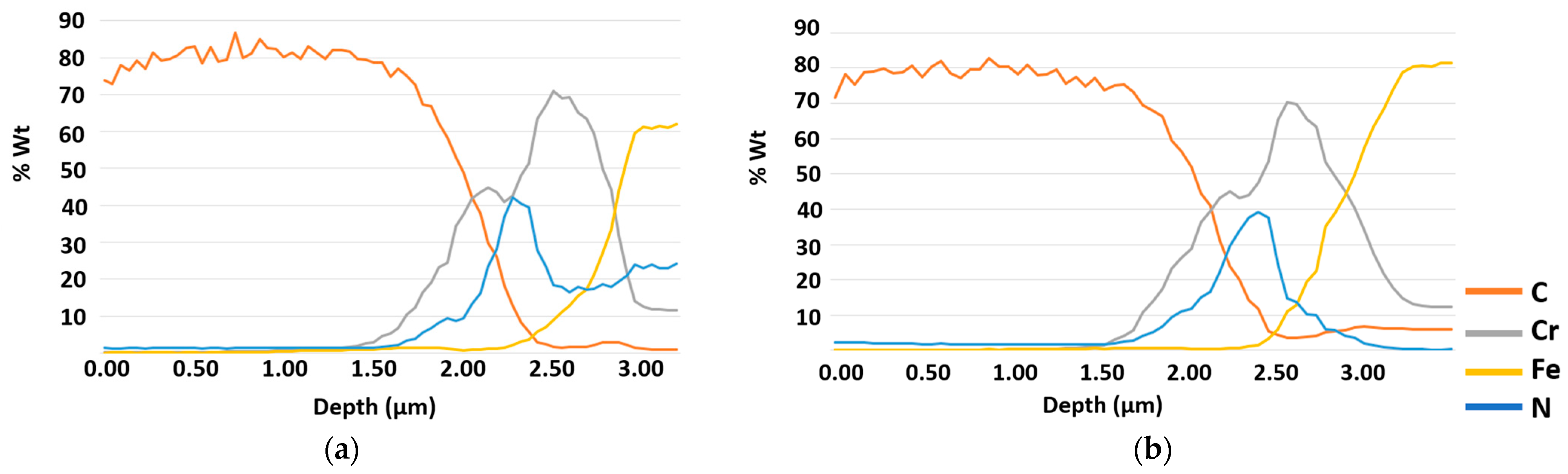
Glow discharge optical emission spectrometry (GD-OES) was employed to analyze the coatings’ chemical composition profiles and thicknesses. The equipment used for this purpose was the JOBIN YVON 100000RF GD-OES from HORIBA Instruments in Kyoto, Japan. To validate the thickness measurements obtained previously, CSM Calotest equipment from CSM Instruments in Needham, MA, USA was used. The thickness was measured using a 30 mm diameter stainless steel ball and a superfine (0.25 µm) diamond water suspension as an abrasive medium. The aim of this additional measurement was to confirm the previously obtained results regarding thickness. Additionally, to comprehend the structure of the coating, a cross-sectional image was obtained using a HITACHI S4800 field emission scanning electron microscope (HITACHI High Technologies Corporation, Tokyo, Japan).
Finally, Raman spectroscopy was employed to assess the structural properties of the DLC films. A ThermoFischer Scientific (Waltham, MA, USA) DXR2 was used to record the Raman spectra by directing a green ion laser with a wavelength of 532 nm onto the coating surface at a power of 8 mW. The resulting Raman spectrum underwent curve-fitting through two Gaussian functions, centered on disordered (D-band) and graphite (G-band) modes. Additionally, the ratio of peak heights was utilized to determine the relative intensity ratio of the D and G bands, denoted as ID/IG.

2.4. Mechanical and Tribological Tests

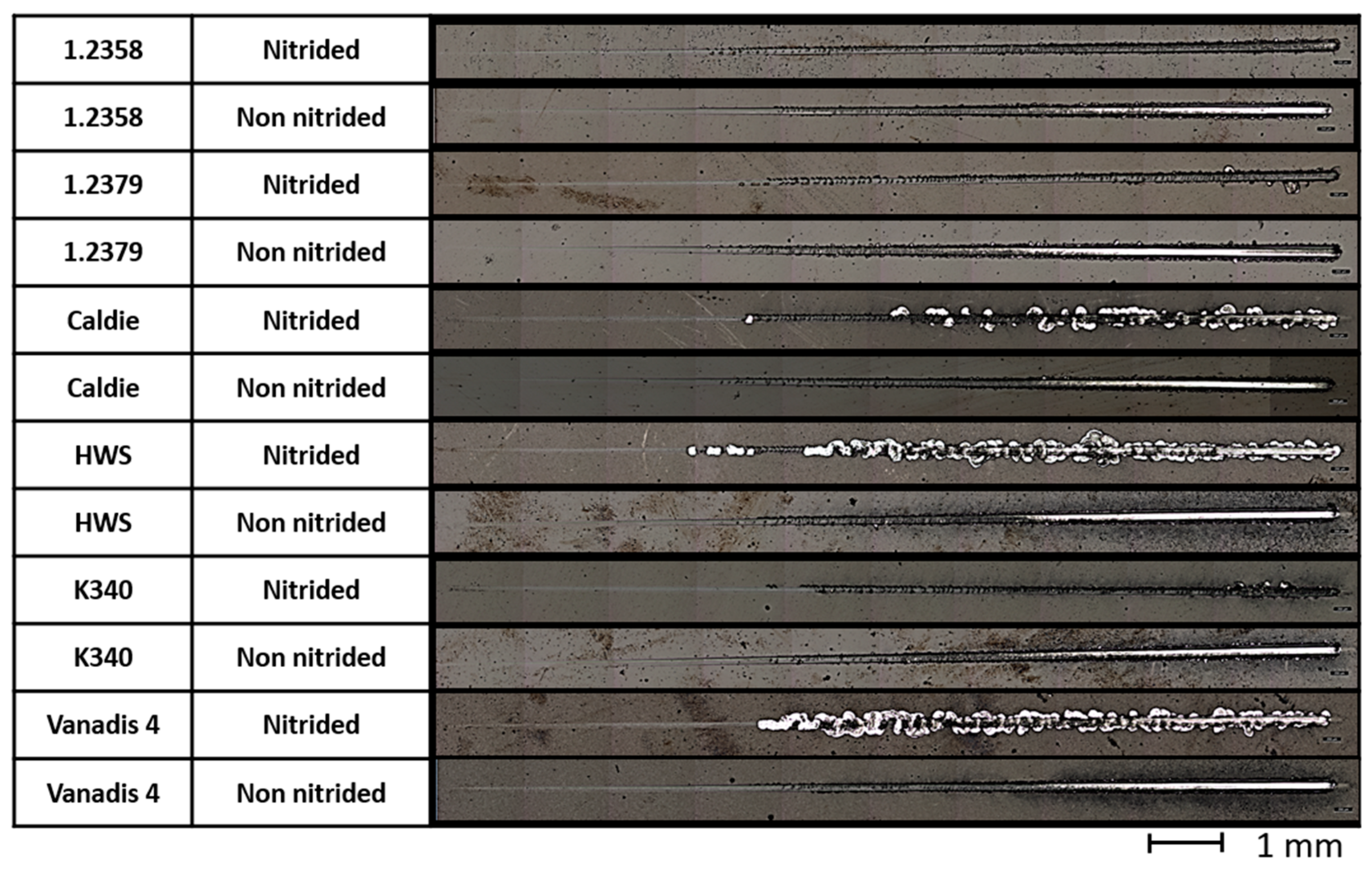
The adhesion between the substrate and coatings was evaluated using a CSM RE-VETEST Scratch tester (Peseux, Switzerland), which was equipped with a diamond Rockwell indenter (EURO 150518 C&N) with a tip radius of 200 µm. The test was performed with a load rate of 100 N/min, a final load of 100 N, a speed of 9.58 mm/min, and a total test length of 10 mm. During the adhesion tests (3 tests in each sample), several signals, including penetration of the indenter within the substrate, acoustic emission, and coefficient of friction, were recorded. The locations where these events occurred were observed through optical microscopy. Based on this information, three critical loads (LC) were determined:
  • The first critical load (LC1): the first cohesive failure observed;
  • The second critical load (LC2): the first adhesive failure appreciated;
  • The third critical load (LC3): a total delamination of the coating or even a critical defect is clearly observed in the reference substrate.
During the scratch tests, a gradual load is applied through the indenter onto the surfaces of the samples. As the load increases, different failure modes become apparent. Initially, failure mechanisms such as plastic deformation, fissurations, and tensile or lateral cracks emerge, which are related to cohesive-type failure mechanisms (LC1). Subsequently, failure mechanisms such as delaminations, cracks by frontal deformation, superficial lifts, or lateral chipping, among others, appear, which are associated with adhesive-type failure mechanisms (LC2). Finally, a critical load is reached, causing more than half of the coating to be removed from the substrate (LC3).
For the tribomechanical tests, a Microtest MT series equipment from Microtest S.A. (Madrid, Spain) was used. Pin-on-disk tests were conducted using 6 mm alumina balls with a maximum surface roughness of Ra
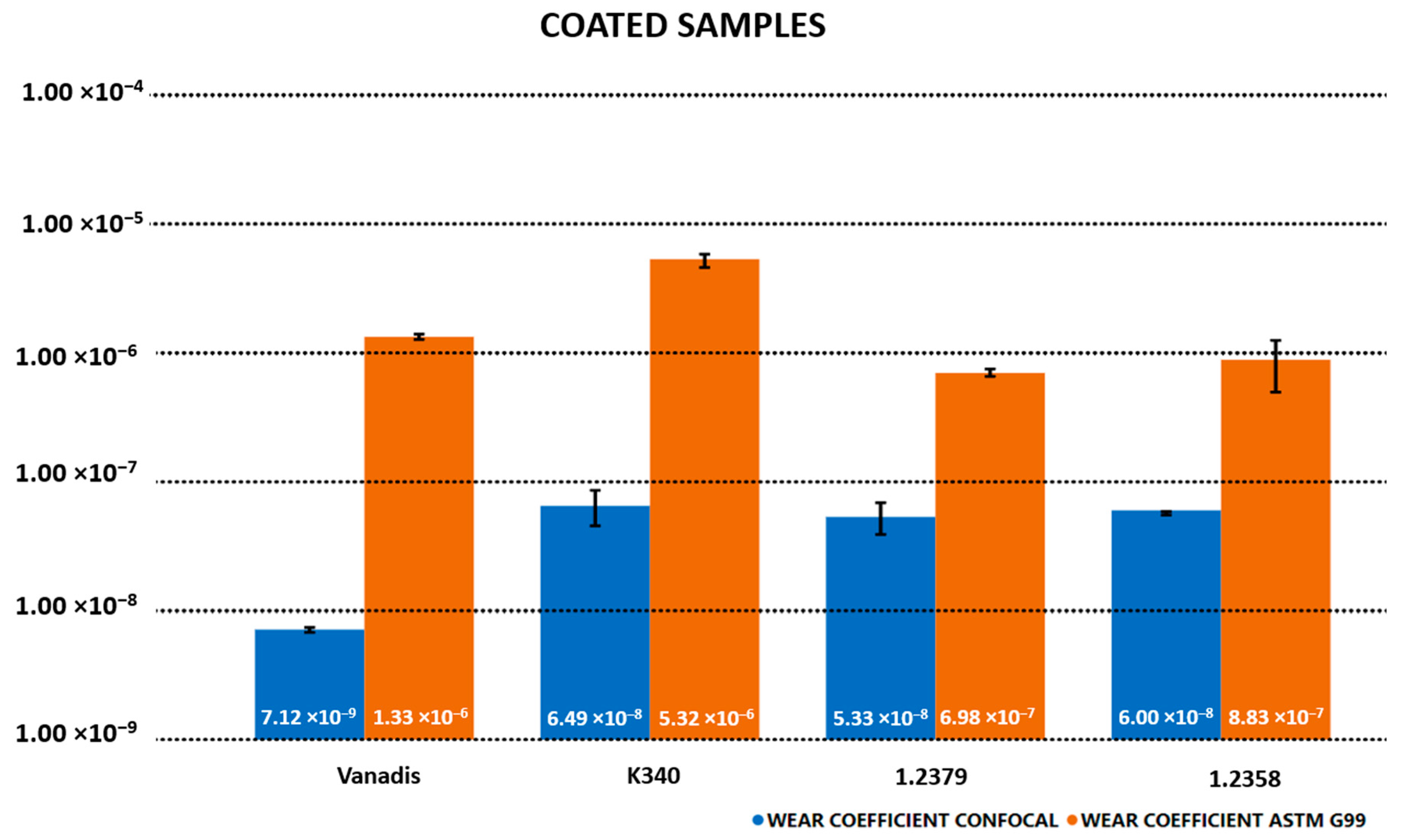
max = 0.050 µm and a hardness of approximately 1650 HV as pins, while various samples of coated and uncoated tool steels were used as disks. The tests were carried out under a load of 40 N, 200 rpm, and 20,000 cycles, which resulted in a Hertzian contact stress of 2.6 GPa. The high-performance tool steels and coatings used in this study required a high load and sufficient revolutions to generate a measurable and homogeneous wear track, similar to the real application cases of these coatings, such as cold forging or forming applications, where high pressures are applied. Similar parameters were used in other studies on this type of coating. The wear tracks were measured using a confocal smart microscope (Sensofar, Terrasa, Spain) and an optical microscope (Sensofar, Terrasa, Spain). The volume loss and wear evaluation were determined through two methods: following ASTM G99 [29] and directly from the confocal measurements of volume loss.
Nanohardness measurements (20 indentations in each sample) were conducted using an MTS NANOINDENTER XP (MTS, Madrid, Spain) (equipped with a Berkovich tip, a maximum depth of 2000 nm, and a maximum load of 10 mN. Once the maximum load was reached, it was maintained for two seconds before initiating the discharge. The Oliver and Pharr method [30] was used to obtain hardness and Young’s modulus values, and the impact of the substrate on the hardness and Young’s modulus was corrected using the Bec et al. thin film model [31].

2.5. Functional Tests

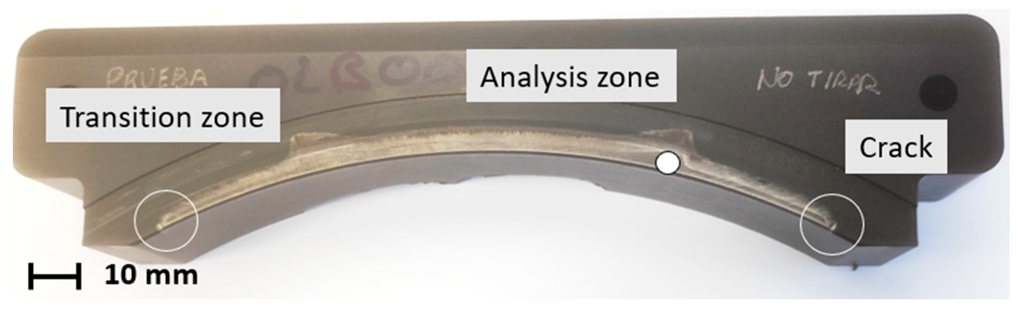
Further experiments were conducted using cold stamping tools to supplement the laboratory tests already described. The forging process performed by the tool involved decreasing the thickness of a structural steel sheet, S235JR, from 6 mm to 2.5 mm (Figure 3). Tests were carried out to examine the behavior of diamond-like carbon (DLC) in these stamping scenarios, using both coated and uncoated tools. The tool substrates were manufactured from 1.2379 steel which had been tempered to 60 HRc. The initial experiment involved testing the DLC-coated tool, evaluating its performance over 580,000 cycles. A comparative analysis was also carried out using the uncoated tool.

3. Results

3.1. Thickness, Structural Properties, and Profile Composition

Figure 4 depicts the results obtained from GD-OES analysis, revealing a coating with a 3 µm thickness. The distribution of elements within the coating was as follows: The initial 1.80 µm layer contains an 80% weight percent concentration of C, followed by a 0.80 µm layer composed of Cr and N. Moving further into the coating, the proportion of N gradually declines, while the concentration of Cr increases, reaching 70% at a depth of 2.50 µm. Beyond this point, the Cr content diminishes, eventually transitioning to the substrate. In the case of the nitrided specimen, the nitrogen content remains constant at 20%, reflecting the impact of the prior nitriding process.
The calotest measurements, executed to establish the resultant coating thickness, are visually represented in Figure 5. Distinct circumferences (indicated by red, yellow, and blue markers in Figure 5) emerge, each corresponding to specific depth levels, arising from the ball’s abrasion-driven motion during the test. The interrelation among these dimensional variations serves as the key to deducing the coating’s thickness. The coated samples exhibit thicknesses of approximately 3 µm. Notably, these results harmonize with the outcomes from glow discharge optical emission spectrometry (GD-OES), illustrated in Figure 4.
Additionally, Figure 6 illustrates the SEM cross-sectional view of the coating, revealing a compact but columnar structure characteristic of DLC coatings. It is also possible to observe the clearly differentiated layers that constitute the whole coating. A first chromium adhesion layer is followed by CrN and CrCN layers, and, finally, the most carbon-rich one. These results are consistent with those obtained using the GDOES technique (Figure 4b) and Calotest (Figure 5).
Figure 7 displays the Raman spectrum associated with the coating. The distinctive D and G bands of carbon, located at approximately 1370 cm−1 and 1550 cm−1, respectively, were discerned by fitting the Raman spectra using two Gaussian functions. The spectrum illustrates the broadening and overlapping of these two bands, indicating a disordered, amorphous carbon structure. With visible excitation at 532 nm in our experiment, the ID/IG ratio was determined to be 0.73. In accordance with the existing literature, the ID/IG ratio typically correlates with the sp2/sp3 fraction [32].

3.2. Nanoindentation Tests

Table 3 shows the results obtained from the nanoindentation test for the complete set of coated specimens. The average hardness values obtained were in the range of 17 to 24 GPa. In particular, the Vanadis steel specimen without nitriding had the highest recorded hardness, 24 GPa. Conversely, the Vanadis specimen subjected to the nitriding process had the lowest average hardness, approximately 17 GPa. Across all specimens, those subjected to nitriding showed significantly inferior results compared to their non-nitrided counterparts. This observation highlights the detrimental effect of the nitriding process on the nanoindentation test results.
In the load displacement profiles, there is a pronounced elastic component for all combinations. Figure 8 shows the profile for the Vanadis sample. Table 3 also presents the hardness ratio: H3/E2. This parameter displays acceptable values in the coating, particularly in the context of non-nitrided samples. Comparisons with other studies are noteworthy; for instance, García et al. [33] reported values of 0.15 for WC: C coatings and 0.45 for ta-C coatings, while Claver et al. [34] presented values of 0.148 and 0.152 for ta-C. The importance of H3/E2 and H/E ratios resides in their use as measures for evaluating resistance to plastic deformation under contact load and elasticity indices, respectively, according to the studies of Leyland et al. [35] and Charitidis et al. [36]. Galvan et al. [37] pointed out that these measures are crucial to determining the toughness and wear resistance of coatings. The notion that a material’s wear resistance can be customized by modifying its elastoplastic properties, often indicated by increasing its hardness or reducing its elastic modulus, is widely acknowledged by Lopes et al. [38]. H3/E2 is linked with a material’s elastic limit. Therefore, an increase in H3/E2 corresponds to an improvement in the coating’s elastic recovery during contact events.

3.3. Adhesion Tests

Scratch tests were carried out on all DLC-coated specimens to evaluate their mechanical performance and adhesion to the underlying substrate. Figure 9 presents the results of the specimens containing Caldie as substrate (Figure 9a for the nitrided Caldie sample and Figure 9b for the non-nitrided Caldie sample). In the nitrided Caldie sample, the initial adhesion failure (LC2) occurred at 17 N, while the substrate’s first appearance (LC3) was at 33 N. The non-nitrided Caldie sample showed more encouraging results, with the first adhesion failure (LC2) occurring at 31 N and the substrate appearing (LC3) at 67 N. The figures demonstrate the correlation between acoustic emission (AE%) and the coefficient of friction (COF), which correspond to normal and tangential forces. By subjecting the specimens to these tests, we analyzed the various failure modes occurring along the scratches and documented the critical loads at which these modes manifested. Our experimental data enabled us to carry out a comparative study of the distinct properties of the various combinations with the primary objective of determining the coating–substrate combination that would exhibit superior adhesion characteristics.
The results of LC2 and LC3 for all specimen combinations can be found in Table 4. There was a clear difference in the value range between nitrided and non-nitrided specimens. Without nitriding, LC2 results ranged from 26 N to 33 N and LC3 results ranged from 67 N to 72 N. In contrast, nitrided specimens exhibited LC2 values ranging from 17 N to 31 N and LC3 values ranging from 28 N to 47 N. The reduction in LC3 values, above all, was particularly remarkable.
Comparing the obtained results with previous research in Table 5, the same conclusion was reached. The specimens that did not receive nitriding achieved similar or even better results. However, the nitrided specimens exhibited a lower level of adhesion quality. The decrease in adhesion between steels and DLC coatings on previously nitrided specimens can be attributed to several interrelated factors. Nitriding can introduce gradients of chemical composition in the surface layer of the steel, resulting in a gradual transition from the nitrided surface to the material’s core. This variation in chemical composition can hinder DLC coating adhesion, as the transition between layers may generate internal stresses and weaken the interfacial bond. Another factor to consider is the potential presence of impurities, inclusions, or other defects in the nitrided layer, which can act as initiation points for delamination or detachment of the DLC coating. Also, it has been noted that the high residual internal stress during the formation of DLC coatings, as well as the large mismatch in the thermal expansion coefficient between DLC and tool steel, make it difficult to achieve strong adhesion between DLC and tool steel substrates [26,39,40]. The high compressive stress of hard DLC coatings often leads to poor adhesion with tool steel substrates, limiting its practical applications. Furthermore, the plastic deformation and fracture of DLC coatings have been attributed by Cheng et al. [41] to higher residual stress and poorer adhesion strength, impacting the cavitation erosion resistance of DLC coatings.
Figure 10 displays microscopy images that reveal the scratch test grooves. Notably, the examination of the nitrided specimens (Caldie, HWS, and Vanadis 4) revealed that substrates became exposed at an earlier stage of the test than expected. As a result, the coating became completely delaminated from the underlying material. This observation is significant and indicates a distinct behavior of the nitrided samples during the scratch test.
The test results clearly demonstrate (Figure 11) the negative impact of nitriding on the adhesion of DLC substrate coatings. The obtained values indicate that the adhesion quality was 20% worse for LC2 values and 48% worse for LC3 values when nitriding was applied. Therefore, it is not recommended to use this DLC coating on nitrided steel. On the other hand, the test results for non-nitrided specimens were quite satisfactory. All six steels exhibited similar behavior, with very similar values observed across the board. The adhesion values for LC2 were approximately 30 N, while the LC3 values reached around 69 N.

3.4. Friction and Wear Tests

The results of the pin on disc tribometer are shown in Figure 12. The results can be divided into two groups. On the one hand, we have the results of the uncoated specimens, which obtained COF values between 0.5 and 0.8. In the case of the samples coated with DLC, values close to 0.1 were obtained. In both cases, there was no difference between the nitrided and non-nitrided samples.
The friction coefficient results were lower than those achieved by Sharifahmadian [42], whereas the friction coefficient of the nitrogen-doped DLC coating grew gradually and eventually reached a value of 0.2, while that for the DLC sample reached a value of 0.3 at the conclusion of the test. The friction coefficients, however, are quite comparable to those listed in Wang et al. [43]. The resulting coefficients of friction were confirmed in this investigation to be tightly correlated with the carbon concentration and crystal phases. It is crucial to note that all coatings showed friction coefficients that were roughly consistent, suggesting that none of them had entirely worn off by the conclusion of the test.
Figure 13 displays the results obtained from all specimens with substrate 1.2379. Similarly to the other cases, the coated specimens were in the region of 0.1, while the uncoated specimens were approximately around 0.6. Notably, the uncoated and non-nitrided specimen displayed an increase in COF up to 0.8 at the end of the test.
Two distinct methods were employed to evaluate volume reduction and the wear coefficient. The first procedure included determining the width of the wear track in accordance with the ASTM G99 regulation, which consequently provided the values for the volume reduction and wear coefficient. The regulation necessitated the calculation of the overall volume reduction using the measured width of the wear track. Subsequently, the wear coefficient was normalized using a formula that related it to the applied load and total sliding distance in the first method. Conversely, the second method employed direct volume loss calculation through a confocal microscope and the Sensoview program (Figure 14). An example of the aspect of the wear tracks obtained after the friction and wear tests was obtained by confocal microscopy. This case was a sample of 1.2379 which was coated and not nitrided. The obtained value was then extrapolated for the whole wear track, following the equation provided in Formula (1). Finally, the wear coefficient was calculated utilizing the same equation as in the initial method.
V   l o s s   c o n f o c a l   ( m 3 ) w e a r   t r a c k   l e n g t h   ( m )   ×   2   ×   п   ×   r   ( m ) = V   loss   ( m 3 )
Table 6 presents a summary of the findings on the volume loss and wear coefficient obtained through the application of both the ASTM G99 method and confocal microscopy for each tested sample. The displayed values are the average outcomes of three tests for each sample. Notably, both methodologies generated results exhibiting a congruent trend, although there was a significant difference of one order of magnitude. This dissimilarity stemmed from the contrasting calculation approaches which were employed: the ASTM G99 standard assumed a wear track with a perfect spherical shape, whereas confocal microscopy recorded the actual, non-ideal shape of the wear track.
Figure 15 presents the results of the coated and non-nitrided samples. In this situation, the results obtained through confocal were more than 1.00 × 10⁻⁸ mm3/Nm, indicating a significant difference of three magnitudes compared to the specimens without coatings. This supports previous research and confirms the observations made by other researchers, who consistently found similar differences in magnitude. Feng et al. [44] achieved a similar wear coefficient of 2.11 × 10⁻⁷ mm3/Nm using a DLC and HSS combination. Also, Chang et al. [45] obtained 2.11 × 10⁻⁷ mm3/Nm using their DLC coating. In addition, it is important to mention that the nitrided samples were analyzed but rejected due to their poor results in the nanoindentation and scratch evaluations. Therefore, the emphasis now shifts to finding the ideal combination for field testing on cold-formed components. The search for this ideal mix is crucial to progressing our research in this area, and it continues to be a key goal as we aim to improve the effectiveness and longevity of these necessary parts.

3.5. Functional Test

This section displays the results obtained from the previously described cold stamping tests. To achieve this, the forging process was initially studied using an uncoated tool, followed by an examination of the same process utilizing a tool coated with DLC. This comparative analysis aimed to scrutinize any potential faults that may have emerged as the tool operated, allowing for a direct comparison between the two tools. Figure 16 depicts the uncoated tool after undergoing 200,000 cycles. In Figure 16b, small cracks are observable, potentially indicative of an early stage preceding fatigue-induced failure in that region. Figure 16c exhibits a larger crack compared to the former; it is more prominent and easily discernible. This crack directly impacted the manufactured piece, necessitating the replacement of the tool to maintain production integrity.
In Figure 17, the uncoated tool is depicted following a rigorous run of 300,000 cycles. Upon closer examination of Figure 17b,c, the details show that the identified cracks exhibit a more significant depth than those observed in the earlier Figure 16. Notably, these fissures seem to have deepened over the extended operational period, marking a progression in their severity. Figure 17b showcases these deeper cracks, suggesting an increased level of structural compromise within the tool. Moving to Figure 17c, a concerning development is evident—a more substantial crack expanded, resulting in a partial fracture of the tool. This breach in the tool’s integrity is visibly conspicuous, indicating the profound impact of cyclic loading and stress over an extended period. The progression from smaller, superficial cracks in Figure 16 to these deeper and now structurally compromising cracks in Figure 17 underlines the incremental degradation of the tool. This gradual deterioration exemplifies the critical impact of cyclic stress and the formation of cracks, ultimately leading to a partial failure of the tool. Such developments emphasize the criticality of maintaining tools in optimal condition to prevent significant failures and uphold operational efficiency.
Small surface cracks in a stamping tool have the potential to initiate a cascade of detrimental effects, leading to tool failure caused by fatigue. These initial fissures may seem inconsequential at first glance, but they can significantly compromise the structural integrity of the tool over time. As the stamping process continues, these minor cracks serve as focal points for stress concentration, exacerbating the conditions that promote crack propagation. Fatigue failure, often initiated by such cracks, is a gradual process where the material weakens due to repetitive loading and unloading cycles. These cracks can gradually grow, extending deeper into the material until they reach a critical point, causing sudden failure or fracture. This not only disrupts the stamping process, but also poses safety hazards and impacts production efficiency.
This section focuses on the analysis of the performance of a coated tool. To achieve this, a detailed investigation was carried out involving the continuous examination of the tool surface during its involvement in the operational process. Throughout the study, series of images were systematically taken during the working cycles for the analysis using confocal microscopy. Figure 18 shows the image of the coated tool after 580,000 cycles. Three different points are noteworthy. Firstly, the transition zone has been comprehensively evaluated as it pertains to the analysis of the transition between the working and non-working zones. Secondly, there is a point for qualitative analysis. Various images were captured in this region while the tool was in operation, enabling us to observe the surface’s gradual changes. Additionally, the crack zone displays a visualized fracture in the tool.
Figure 19 exhibits a range of images of the same area (analysis zone of Figure 18), allowing for observation of the changes that the surface of the tool was subjected to during its working life. Figure 19a represents the surface before use, which had a Sa value of 0.5309 µm, which is consistent with previous observations [46]. In this picture, the grooves that resulted from the grinding of the parts are visible, a typical component of cold stamping tools. Figure 19b, on the other hand, shows that measurements of the surface after 80,000 cycles led to an Sa value of 0.3829 µm. The grinding grooves decreased, revealing the initial marks from material displacement. Figure 19c displays the surface after 160,000 cycles with a Sa 0.3602 µm. The marks showed that the material displacement became more distinct, and the direction of material flow was observable. Figure 19d shows the surface after 320,000 cycles, with a Sa value of 0.2881 µm. Figure 19e presents the surface after 580,000 cycles, with a Sa 0.3401 µm. It can be noted that the material displacement created new vertical grooves while the horizontal scratches remained. The direction of the grooves plays a significant role in determining friction. The images illustrate the gradual changes in the surface. Holmberg et al. [47] studied this behavior, highlighting the importance of surface direction in influencing friction.
Figure 20 depicts the crack zone of Figure 18, even though it may not be immediately evident visually. This crack serves as the starting point for potential tool failure. Additionally, the image displays the surface profile on the Z-axis, revealing three distinct zones within this profile. On one side, there is an area of the tool that remained inactive and unchanged, experiencing no wear. On the other side, there is the working zone where the fault was identified. Within this region, the crack extends to a depth of 55 µm.
Figure 21 displays the transition zone between the operational section and the inactive segment of the tool (Figure 18). The working area displayed wear after 580,000 usage cycles. To determine the degree of wear, a Z-axis profile was generated. The confocal image reveals that the coating eroded by approximately 2 µm. This observation indicates that, although the outermost carbon layer was completely worn away, the intermediate layer containing nitrogen and chromium persevered and was able to withstand wear even after 580,000 cycles. Furthermore, in Figure 18, we can see that the carbon, which was once dark-colored, gradually faded out in the regions where the tool was actively employed, providing additional insight into the wear patterns and material performance over time.

4. Discussion

The laboratory results for the DLC coatings have been satisfactory overall. In general, no significant differences were observed among the various substrates used in the tests. While it is true that all these substrates belong to the same group of steels (specifically, tool steels) and share a tempered hardness of 60 HRc, as detailed in previous sections, it is important to note that these steels come from different quality grades, including conventional, remelted, and powder metallurgy steels, leading to evident differences among them, such as grain size. Considering this diversity of substrate quality, it can be concluded that, although it is essential for the steel to meet certain minimum standards for the stamping application studied in this work, choosing a higher-quality steel does not automatically guarantee an improvement in the DLC coating–steel combination. This finding underscores the complexity of the interaction between steel type and DLC coating in terms of performance in specific applications, emphasizing the importance of a detailed and specific evaluation of each material combination in the context of the particular application under investigation.
The relationship between hardness (H3) and elastic modulus (E2) falls within an acceptable range, suggesting outstanding resistance to plastic deformation and notable elasticity. The favorable correlation between hardness and elastic modulus indicates a promising ability not only to withstand structural alterations under stress conditions, but also to recover during deformation processes. This highlights the inherent mechanical strength of the material. This will directly impact the influence of the DLC coating on the protection of forming tools in terms of fatigue, as the DLC coating, aside from its proven wear protection, will positively affect this aspect as well. Scratch tests have highlighted the excellent adhesion quality of this DLC coating when the substrate has not undergone prior nitriding. Generally, DLC coatings do not exhibit good adhesion results, but the magnetron sputtering deposition method offers a distinctive advantage in this regard, overcoming limitations associated with other methods, such as arc deposition. It is important to note that nitriding has a negative impact on scratch adhesion tests between the substrate and the DLC coating. In contrast, all samples used in the tests that were not subjected to the nitriding process exhibited superior adhesion results, emphasizing the influence of this treatment on adhesion properties. Regarding the friction coefficient of the DLC coating, as anticipated, values around 0.1 were obtained. These results align with previous research and coincide with findings from other researchers in this field. This confirmation represents one of the significant inherent advantages of this type of coating. On the other hand, the coated samples showed a significantly higher degree of wear resistance compared to those without coating. The results obtained through confocal microscopy, with values around 1.00 × 10⁻⁸ mm3/Nm, indicate a substantial difference compared to uncoated samples. The quantified improvement for DLC-coated samples was measured in three orders of magnitude, significantly highlighting the remarkable enhancement in durability and performance when subjected to rigorous wear tests. This finding suggests that the DLC coating provides an effective protective layer, contributing to extending the material’s lifespan and its ability to resist wear associated with specific applications.
Finally, for functional tests, the application of DLC coatings acts as a robust safeguard against fatigue in cold stamping tools. These coatings effectively act as a shield, improving the resistance and longevity of tools by mitigating the effects of repetitive stress and cyclic loading encountered during the cold stamping process. The exceptional hardness, wear resistance, and low-friction properties of the DLC coating contribute significantly to reducing wear and preventing the onset of fatigue-related damage in tools. This protection ensures an extended lifespan for tools and maintains operational efficiency in cold stamping applications.

5. Conclusions

Below are the most important conclusions drawn from this work, including those derived from laboratory tests and findings obtained from functional tests using cold stamping tools.
  • The hardness (H3) to elastic modulus (E2) ratio falls within an acceptable range, indicating commendable resistance to plastic deformation and elasticity. The ratio’s favorable correlation between hardness and elastic modulus implies a promising capacity to endure both structural alterations under stress and recuperation during deformation, demonstrating the material’s mechanical strength.
  • Nitriding has a negative impact on the adhesion scratch tests between the substrate and the DLC coating. Conversely, all the samples used in the tests that were not subjected to the nitriding process showed superior adhesion results.
  • The samples that were coated showed a much higher degree of wear resistance compared to those that were uncoated. The results obtained through confocal microscopy were higher than 1.00 × 10⁻⁸ mm3/Nm, indicating a significant difference compared to the specimens without coatings. The improvement in the DLC-coated samples was measured in the range of three orders of magnitude, highlighting a significant enhancement in the durability and performance of the specimens when subjected to wear testing.
  • Uncoated tools exhibited progressive and severe structural degradation, with the crack formation leading to potential tool failure over prolonged usage cycles.
  • Coated tools displayed wear patterns and exhibited wear-resistant behavior. The DLC coating proved to withstand wear even after 580,000 cycles. Although material displacement occurred on the surface, the coating had the ability to resist wear as the carbon layer gradually wore away, leaving the underlying surface intact.
The application of DLC (diamond-like carbon) coatings serves as a robust safeguard against fatigue for cold stamping tools. These coatings act as a shield, effectively enhancing the tools’ endurance and longevity by mitigating the effects of repetitive stress and cyclic loading encountered during the cold stamping process. The DLC coatings’ exceptional hardness, wear resistance, and low friction properties contribute significantly to reducing wear and preventing the onset of fatigue-related damage to the tools. This protection ensures prolonged tool life and sustains operational efficiency in cold stamping applications.

Author Contributions

Conceptualization, C.J.L.-P. and J.A.G.; methodology, A.C. and N.S.; software, J.F.P.; validation, E.B.; formal analysis, A.C. and C.C.; writing—original draft, E.B.; writing—review and editing, E.B.; visualization, F.M. All authors have read and agreed to the published version of the manuscript.

Funding

This research was funded by the Government of Navarre, grant number 0011-1408-2020-000024.

Informed Consent Statement

Not applicable.

Data Availability Statement

For more information: https://www.nuadi.com/contact/ (accessed on 22 January 2024).

Acknowledgments

We would like to express our gratitude to the Government of Navarre for their financial assistance with a part of this study.

Conflicts of Interest

Eneko Barba was employed by the company NUADI EUROPE. Francesc Montalà, Neus Sala and Carles Colominas were employed by the company FLUBETECH. José F. Palacio was employed by the company AIN. The remaining authors declare that the research was conducted in the absence of any commercial or financial relationships that could be construed as a potential conflict of interest.

References

  1. Silva, W.; Jesus, L.; Carneiro, J.; Souza, P.; Martins, P.; Trava-Airoldi, V. Performance of carbide tools coated with DLC in the drilling of SAE 323 aluminum alloy. Surf. Coat. Technol. 2015, 284, 404–409. [Google Scholar] [CrossRef]
  2. Grill, A. Review of the tribology of diamond-like carbon. Wear 1993, 168, 143–153. [Google Scholar] [CrossRef]
  3. Zhang, T.; Deng, Q.; Liu, B.; Wu, B.; Jing, F.; Leng, Y.; Huang, N. Wear and corrosion properties of diamond like carbon (DLC) coating on stainless steel, CoCrMo and Ti6Al4V substrates. Surf. Coat. Technol. 2015, 273, 12–19. [Google Scholar] [CrossRef]
  4. De Feo, M.; Bouchet, M.D.B.; Minfray, C.; Le Mogne, T.; Meunier, F.; Yang, L.; Thiebaut, B.; Martin, J. MoDTC lubrication of DLC-involving contacts. Impact of MoDTC degradation. Wear 2016, 348–349, 116–125. [Google Scholar] [CrossRef]
  5. Kosarieh, S.; Morina, A.; Lainé, E.; Flemming, J.; Neville, A. The effect of MoDTC-type friction modifier on the wear performance of a hydrogenated DLC coating. Wear 2013, 302, 890–898. [Google Scholar] [CrossRef]
  6. Bueno, A.; Solis, J.; Zhao, H.; Wang, C.; Simões, T.; Bryant, M.; Neville, A. Tribocorrosion evaluation of hydrogenated and silicon DLC coatings on carbon steel for use in valves, pistons and pumps in oil and gas industry. Wear 2018, 394–395, 60–70. [Google Scholar] [CrossRef]
  7. Kovacı, H.; Baran, A.F.; Yetim, A.; Bozkurt, Y.; Kara, L.; Çelik, A. The friction and wear performance of DLC coatings deposited on plasma nitrided AISI 4140 steel by magnetron sputtering under air and vacuum conditions. Surf. Coat. Technol. 2018, 349, 969–979. [Google Scholar] [CrossRef]
  8. Toboła, D.; Liskiewicz, T.; Yang, L.; Khan, T.; Boroń, Ł. Effect of mechanical and thermochemical tool steel substrate pre-treatment on diamond-like carbon (DLC) coating durability. Surf. Coat. Technol. 2021, 422, 127483. [Google Scholar] [CrossRef]
  9. Sresomroeng, B.; Premanond, V.; Kaewtatip, P.; Khantachawana, A.; Koga, N.; Watanabe, S. Anti-adhesion performance of various nitride and DLC films against high strength steel in metal forming operation. Diam. Relat. Mater. 2010, 19, 833–836. [Google Scholar] [CrossRef]
  10. Sulaiman, M.; Farahana; Bienk, K.; Nielsen, C.; Bay, N. Effects of DLC/TiAlN-coated die on friction and wear in sheet-metal forming under dry and oil-lubricated conditions: Experimental and numerical studies. Wear 2019, 438–439, 203040. [Google Scholar] [CrossRef]
  11. Ghiotti, A.; Bruschi, S. Tribological behaviour of DLC coatings for sheet metal forming tools. Wear 2011, 271, 2454–2458. [Google Scholar] [CrossRef]
  12. Li, H.; Wu, X.; Li, G.; Zhou, D. Chipping damage of die for trimming advanced high-strength steel sheet: Evaluation and analysis. J. Am. Acad. Dermatol. 2020, 285, 116787. [Google Scholar] [CrossRef]
  13. Cora, N.; Koç, M. Experimental investigations on wear resistance characteristics of alternative die materials for stamping of advanced high-strength steels (AHSS). Int. J. Mach. Tools Manuf. 2009, 49, 897–905. [Google Scholar] [CrossRef]
  14. Zappelino, B.; Almeida, E.d.S.d.; Krelling, A.; da Costa, C.; Fontana, L.; Milan, J. Tribological behavior of duplex-coating on Vanadis 10 cold work tool steel. Wear 2020, 442–443, 203133. [Google Scholar] [CrossRef]
  15. Chapelle, P.; Noël, C.; Risacher, A.; Jourdan, J.; Jardy, A. Optical investigation of the behavior of the electric arc and the metal transfer during vacuum remelting of a Ti alloy. J. Am. Acad. Dermatol. 2014, 214, 2268–2275. [Google Scholar] [CrossRef]
  16. Risacher, A.; Chapelle, P.; Jardy, A.; Escaffre, J.; Poisson, H. Electric current partition during vacuum arc remelting of steel: An experimental study. J. Am. Acad. Dermatol. 2013, 213, 291–299. [Google Scholar] [CrossRef]
  17. Cui, J.; Li, B.; Liu, Z.; Qi, F.; Xu, J.; Zhang, J. Comparative investigation on ingot evolution and product quality under different arc distributions during vacuum arc remelting process. J. Mater. Res. Technol. 2022, 18, 3991–4006. [Google Scholar] [CrossRef]
  18. Yang, S.; Tian, Q.; Yu, P.; Yang, S.; Liu, W.; Li, J. Numerical simulation and experimental study of vacuum arc remelting (VAR) process for large-size GH4742 superalloy. J. Mater. Res. Technol. 2023, 24, 2828–2838. [Google Scholar] [CrossRef]
  19. Modabberasl, A.; Kameli, P.; Ranjbar, M.; Salamati, H.; Ashiri, R. Fabrication of DLC thin films with improved diamond-like carbon character by the application of external magnetic field. Carbon 2015, 94, 485–493. [Google Scholar] [CrossRef]
  20. Mano, H.; Ohana, T. Evaluation of anti-adhesion characteristics of diamond-like carbon film using high-frequency, linear-oscillation tribometer. Wear 2017, 386–387, 188–194. [Google Scholar] [CrossRef]
  21. Erdemir, A.; Eryilmaz, O.; Kim, S. Effect of tribochemistry on lubricity of DLC films in hydrogen. Surf. Coat. Technol. 2014, 257, 241–246. [Google Scholar] [CrossRef]
  22. Podgornik, B.; Vizintiň, J. Influence of substrate treatment on the tribological properties of DLC coatings. Diam. Relat. Mater. 2001, 10, 2232–2237. [Google Scholar] [CrossRef]
  23. Dalibon, E.L.; Charadia, R.; Cabo, A.; Trava-Airoldi, V.; Brühl, S.P. Evaluation of the mechanical behaviour of a DLC film on plasma nitrided AISI 420 with different surface finishing. Surf. Coat. Technol. 2013, 235, 735–740. [Google Scholar] [CrossRef]
  24. Dalibón, E.L.; Heim, D.; Forsich, C.; Rosenkranz, A.; Guitar, M.A.; Brühl, S.P. Characterization of thick and soft DLC coatings deposited on plasma nitrided austenitic stainless steel. Diam. Relat. Mater. 2015, 59, 73–79. [Google Scholar] [CrossRef]
  25. Tillmann, W.; Vogli, E.; Hoffmann, F.; Kemdem, P. Influence of substrate nitriding on adhesion, friction and wear resistance of DLC (diamond-like carbon)-coatings. Key Eng. Mater. 2010, 438, 211–218. [Google Scholar] [CrossRef]
  26. Silva, W.; Trava-Airoldi, V.; Chung, Y. Surface modification of 6150 steel substrates for the deposition of thick and adherent diamond-like carbon coatings. Surf. Coat. Technol. 2011, 205, 3703–3707. [Google Scholar] [CrossRef]
  27. Ashtijoo, P.; Bhattacherjee, S.; Sutarto, R.; Hu, Y.; Yang, Q. Fabrication and characterization of adherent diamond-like carbon based thin films on polyethylene terephthalate by end hall ion beam deposition. Surf. Coat. Technol. 2016, 308, 90–97. [Google Scholar] [CrossRef]
  28. Uchidate, M.; Liu, H.; Iwabuchi, A.; Yamamoto, K. Effects of water environment on tribological properties of DLC rubbed against brass. Wear 2009, 267, 1589–1594. [Google Scholar] [CrossRef]
  29. ASTM G99; Standard Test Method for Wear and Friction Testing with a Pin-on-Disk or Ball-on-Disk Apparatus. ASTM: West Conshohocken, PA, USA, 2017.
  30. Oliver, W.C.; Pharr, G.M. An improved technique for determining hardness and elastic modulus using load and displacement sensing indentation experiments. J. Mater. Res. 1992, 7, 1564–1583. [Google Scholar] [CrossRef]
  31. Bec, S.; Tonck, A.; Loubet, J.L. A simple guide to determine elastic properties of films on substrate from nanoindentation experiments. Philos. Mag. 2006, 86, 5347–5358. [Google Scholar] [CrossRef]
  32. Ferrari, A.C.; Robertson, J. Interpretation of Raman spectra of disordered and amorphous carbon. Phys. Rev. B 2000, 61, 14095–14107. [Google Scholar] [CrossRef]
  33. García, J.A.; Rivero, P.J.; Barba, E.; Fernández, I.; Santiago, J.A.; Palacio, J.F.; Fuente, G.G.; Rodríguez, R.J. A comparative study in the tribological behavior of DLC coatings deposited by HiPIMS technology with positive pulses. Metals 2020, 10, 174. [Google Scholar] [CrossRef]
  34. Claver, A.; Jiménez-Piqué, E.; Palacio, J.F.; Almandoz, E.; Fernández de Ara, J.F.; Fernández, I.; Santiago, J.A.; Barba, E.; García, J.A. Comparative Study of Tribomechanical Properties of HiPIMS with Positive Pulses DLC Coatings on Different Tools Steels. Coatings 2020, 11, 28. [Google Scholar] [CrossRef]
  35. Leyland, A.; Matthews, A. On the significance of the H/E ratio in wear control: A nanocomposite coating approach to optimised tribological behaviour. Wear 2000, 246, 1–11. [Google Scholar] [CrossRef]
  36. Charitidis, C.A. Nanomechanical and nanotribological properties of carbon-based thin films: A review. Int. J. Refract. Met. Hard Mater. 2010, 28, 51–70. [Google Scholar] [CrossRef]
  37. Galvan, D.; Pei, Y.T.; De Hosson, J.T.M. Deformation and failure mechanism of nano-composite coatings under nano-indentation. Surf. Coat. Technol. 2006, 200, 6718–6726. [Google Scholar] [CrossRef]
  38. Lopes, B.B.; Rangel, R.C.C.; Antonio, C.A.; Durrant, S.F.; Cruz, V.C.; Rangel, E.C. Mechanical and Tribological Properties of Plasma Deposited a-C:H:Si:O Films. In Nanoindentation in Materials Science; InTech: Houston, TX, USA, 2012. [Google Scholar] [CrossRef]
  39. Sonoda, T.; Nakao, S.; Ikeyama, M. Coating of Die Steel Substrates with DLC/Ti Bi-Layered Films by Magnetron DC Sputtering. Trans. Mater. Res. Soc. Jpn. 2011, 36, 91–94. [Google Scholar] [CrossRef]
  40. Silva, W.d.M.; Carneiro, J.R.G.; Trava-Airoldi, V.J. XPS, XRD and laser raman analysis of surface modified of 6150 steel substrates for the deposition of thick and adherent diamond-like carbon coatings. Mater. Res. 2013, 16, 603–608. [Google Scholar] [CrossRef]
  41. Cheng, F.; Ji, W.; Zhao, J. Influence of adhesion strength on cavitation erosion resistance of diamond-like carbon coating. Ind. Lubr. Tribol. 2019, 71, 724–730. [Google Scholar] [CrossRef]
  42. Sharifahmadian, O.; Mahboubi, F. A comparative study of microstructural and tribological properties of N-DLC/DLC double layer and single layer coatings deposited by DC-pulsed PACVD process. Ceram. Int. 2019, 45, 7736–7742. [Google Scholar] [CrossRef]
  43. Wang, L.; Li, L.; Kuang, X. Effect of substrate bias on microstructure and mechanical properties of WC-DLC coatings deposited by HiPIMS. Surf. Coat. Technol. 2018, 352, 33–41. [Google Scholar] [CrossRef]
  44. Feng, L.; Hu, J.; Yan, S.; He, Z.; Shi, J.; Li, J. Effect of high-speed steel surface nitriding treatment on adhesion and wear resistance properties of nitrogen-doped diamond-like carbon coatings. Diam. Relat. Mater. 2023, 136, 110006. [Google Scholar] [CrossRef]
  45. Chang, S.-H.; Tang, T.-C.; Huang, K.-T.; Liu, C.-M. Investigation of the characteristics of DLC films on oxynitriding-treated ASP23 high speed steel by DC-pulsed PECVD process. Surf. Coat. Technol. 2014, 261, 331–336. [Google Scholar] [CrossRef]
  46. Barba, E.; Salcedo, D.; Claver, A.; Luri, R.; Garcia, J.A. Influence of Friction Coefficient on the Performance of Cold Forming Tools. Metals 2023, 13, 960. [Google Scholar] [CrossRef]
  47. Holmberg, K.; Laukkanen, A.; Hakala, T.; Ronkainen, H.; Suhonen, T.; Wolski, M.; Podsiadlo, P.; Woloszynski, T.; Stachowiak, G.; Gachot, C.; et al. Topography orientation effects on friction and wear in sliding DLC and steel contacts, part 3: Experiments under dry and lubricated conditions. Wear 2021, 486–487, 204093. [Google Scholar] [CrossRef]
Figure 1. Samples before and after coating process. Laboratory specimens (a) and forming tool (b).
Coatings 14 00159 g001
Figure 2. Process chamber including DC (direct current) targets.
Coatings 14 00159 g002
Figure 3. Diagram of the 6 mm thickness sheet steel forming process: (a) initial and (b) final configuration.
Coatings 14 00159 g003
Figure 4. Glow discharge optical emission spectrometry (GD-OES) concentration profiles in 1.2379 sample: nitrided (a) and not nitrided (b).
Coatings 14 00159 g004
Figure 5. Calotest crater used to determine the resultant thickness for the 1.2379 sample without nitriding.
Coatings 14 00159 g005
Figure 6. Cross-section SEM image for the sample of DLC coating.
Coatings 14 00159 g006
Figure 7. Raman spectra of the coated sample 1.2379 without nitriding (green curve corresponds to the Raman spectra, yellow corresponds to the D-peak fit and blue to the G-peak fit).
Coatings 14 00159 g007
Figure 8. Nanoindentation curve for a specific final load of 10,000 µN in a Vanadis sample without nitriding.
Coatings 14 00159 g008
Figure 9. Example of a scratch test. Friction coefficient (blue) and acoustic emission (red). Coated and nitrided Caldie sample (a). Coated and non-nitrided Caldie sample (b).
Coatings 14 00159 g009
Figure 10. Scratch test grooves of all samples.
Coatings 14 00159 g010
Figure 11. Comparative graph of LC2 and LC3 average values, including all the coated samples (1.2358, 1.2379, Caldie, HWS, K340, and Vanadis).
Coatings 14 00159 g011
Figure 12. Friction coefficient of all the combinations.
Coatings 14 00159 g012
Figure 13. Results for the friction coefficient of the 1.2379 samples.
Coatings 14 00159 g013
Figure 14. Example of the aspect of the wear tracks obtained after the friction and wear tests, obtained by confocal microscopy. In this case, the sample of 1.2379 was coated and not nitrided.
Coatings 14 00159 g014
Figure 15. Comparative graph of the values related to wear coefficients, calculated by both methods, for the coated and non-nitrided samples.
Coatings 14 00159 g015
Figure 16. The uncoated tool (1.2379 steel) after 200,000 cycles (a) and the detail of each failure (b,c).
Coatings 14 00159 g016
Figure 17. The uncoated tool (1.2379 steel) after 300,000 cycles (a) and the details of each failure (b,c).
Coatings 14 00159 g017
Figure 18. DLC-coated tool (1.2329) after 580,000 cycles.
Coatings 14 00159 g018
Figure 19. Confocal image (λS = 8.00 µm, λC = 0.08 mm) of the analysis zone after (a) 0 cycles (Sa 0.5309 µm), (b) 80,000 cycles (Sa 0.3829 µm), (c) 160,000 cycles (Sa 0.3602 µm), (d) 320,000 cycles (Sa 0.2881 µm), and (e) 580,000 cycles (Sa 0.3401 µm).
Coatings 14 00159 g019
Figure 20. Confocal crack image (λS = 8.00 µm, λC = 0.08 mm) and the Z profile (white vector direction).
Coatings 14 00159 g020
Figure 21. Z profile (λS = 8.00 µm, λC = 0.08 mm) of the transition between the working (580,000 cycles) and non-working zones.
Coatings 14 00159 g021
Table 1. Chemical composition of the tested steels (wt.%).
SubstrateC (%)Si (%)Cr (%)V (%)Mn (%)Mo (%)
1.23580.60-4.500.20-0.50
1.23791.550.3011.300.750.300.75
CALDIE0.700.205.000.500.502.30
HWS1.081.387.802.660.341.86
K3401.100.908.300.500.402.10
VANADIS 41.400.404.703.700.403.50
Table 2. Stages of the DLC coating application process.
ProcessTime (min)Chamber Pressure (mPa)Temperature (°C)TargetsQuantity of TargetsTargets Power (W)
Vacuum4590
Heating905250
Ion Etching60350200
Cr layer5300200Cr22500
CrN layer45400200Cr22500
CrCN layer45400200Cr + C2 + 22500
DLC layer120400180C21800
Table 3. Summary of the experimental data derived from the nanoindentation curves such as the resultant hardness (H), Young modulus (E), and the H3/E2 relationship, respectively.
SubstrateNitridingCoatingHardness (GPa)Young Module (GPa)H3/E2
1.2358YESDLC19 ± 3126 ± 120.43
1.2358NODLC22 ± 4130 ± 180.63
1.2379YESDLC20 ± 4130 ± 180.47
1.2379NODLC20 ± 5128 ± 130.49
CALDIEYESDLC18 ± 3119 ± 120.41
CALDIENODLC22 ± 5141 ± 170.54
HWSYESDLC19 ± 5126 ± 190.43
HWSNODLC21 ± 5134 ± 170.52
K340YESDLC18 ± 6109 ± 180.49
K340NODLC19 ± 4116 ± 150.51
VANADISYESDLC17 ± 5107 ± 180.43
VANADISNODLC24 ± 6147 ± 310.64
Table 4. Summary of critical load values obtained for each sample from the scratch test.
SubstrateNitridingCoatingLC2 (N)LC3 (N)
1.2358YESDLC20 ± 636 ± 4
1.2358NODLC29 ± 171 ± 3
1.2379YESDLC31 ± 239 ± 3
1.2379NODLC29 ± 372 ± 4
CALDIEYESDLC17 ± 333 ± 2
CALDIENODLC31 ± 267 ± 3
HWSYESDLC21 ± 228 ± 1
HWSNODLC26 ± 667 ± 1
K340YESDLC35 ± 247 ± 1
K340NODLC31 ± 369 ± 3
VANADIS 4YESDLC17 ± 334 ± 2
VANADIS 4NODLC33 ± 569 ± 2
Table 5. Compilation of critical load values acquired through the scratch test for each individual sample on previous works.
ReferenceSubstrateNitridingCoatingDeposition TechniqueLC2 (N)LC3 (N)
[34]K360NOta-CHiPIMS29 ± 250 ± 4
[34]Vanadis 4NOta-CHiPIMS25 ± 340 ± 1
[34]VancronNOta-CHiPIMS24 ± 350 ± 5
[33]1.2379NOta-CHiPIMS18 ± 349 ± 2
Table 6. Summary data of wear coefficient measured using ASTM G99 and confocal methods.
SubstrateNitridingCoatingWear Coefficient ASTM G99 (mm3/Nm)Wear Coefficient Confocal (mm3/Nm)
1.2358NONO(2.76 ± 0.52) × 10−5(1.05 ± 0.13) × 10−5
1.2358YESNO(1.35 ± 0.66) × 10−5(1.09 ± 0.47) × 10−5
1.2358NODLC(8.83 ± 2.84) × 10−7(6.00 ± 0.45) × 10−8
1.2358YESDLC(2.12 ± 0.41) × 10−6(7.35 ± 0.75) × 10−8
1.2379NONO(2.64 ± 0.51) × 10−5(8.22 ± 0.35) × 10−6
1.2379YESNO(1.88 ± 0.38) × 10−5(9.33 ± 0.69) × 10−6
1.2379NODLC(6.98 ± 1.24) × 10−7(5.33 ± 0.74) × 10−8
1.2379YESDLC(4.67 ± 0.87) × 10−6(1.34 ± 0.59) × 10−7
CALDIENONO(4.08 ± 0.12) × 10−5(1.23 ± 0.04) × 10−5
CALDIEYESNO(1.28 ± 0.67) × 10−5(8.31 ± 1.02) × 10−6
CALDIEYESDLC(1.18 ± 0.56) × 10−6(7.47 ± 0.55) × 10−8
HWSNONO(1.12 ± 0.23) × 10−4(1.87 ± 0.72) × 10−5
HWSYESNO(3.29 ± 1.22) × 10−5(2.00 ± 0.63) × 10−5
K340NONO(1.51 ± 0.88) × 10−4(2.59 ± 0.59) × 10−5
K340YESNO(2.98 ± 1.44) × 10−5(1.13 ± 0.47) × 10−5
K340NODLC(5.32 ± 0.61) × 10−6(6.49 ± 1.59) × 10−8
VANADISNONO(2.81 ± 0.87) × 10−5(1.14 ± 0.36) × 10−5
VANADISYESNO(2.62 ± 0.54) × 10−5(1.53 ± 1.03) × 10−5
VANADISNODLC(1.33 ± 0.96) × 10−6(7.12 ± 0.71) × 10−9
VANADISYESDLC(1.09 ± 0.29) × 10−6(4.51 ± 0.48) × 10−8
Disclaimer/Publisher’s Note: The statements, opinions and data contained in all publications are solely those of the individual author(s) and contributor(s) and not of MDPI and/or the editor(s). MDPI and/or the editor(s) disclaim responsibility for any injury to people or property resulting from any ideas, methods, instructions or products referred to in the content.

