Article

Functionalization of Plasma Electrolytic Oxidation/Sol–Gel Coatings on AZ31 with Organic Corrosion Inhibitors

1
Departamento de Ingeniería Química y de Materiales, Facultad de Ciencias Químicas, Universidad Complutense, 28040 Madrid, Spain
2
Institut Laue-Langevin, 71 Avenue des Martyrs, 38000 Grenoble, France
3
Department of Materials Science, Materials Institute, Faculty of Engineering, University of Mons, 20 Place du Parc, 7000 Mons, Belgium
*
Author to whom correspondence should be addressed.
Coatings 2024, 14(1), 84; https://doi.org/10.3390/coatings14010084
Submission received: 11 December 2023 / Revised: 4 January 2024 / Accepted: 5 January 2024 / Published: 7 January 2024
(This article belongs to the Special Issue Plasma Electrolytic Oxidation (PEO) Coatings, 2nd Edition)

Abstract

:
In this investigation, the sol–gel method is employed along with a corrosion inhibitor to seal a plasma electrolytic oxidation (PEO) coating, aiming to improve the long-term corrosion resistance of the AZ31 Mg alloy. Following an initial screening of corrosion inhibitors, 8-hydroxyquinoline (8HQ) is incorporated into the hybrid PEO/sol–gel system using two methods: (i) post-treatment of the PEO layer through immersion in an inhibitor-containing solution; (ii) loading the inhibitor into the sol–gel precursor. The characterization includes scanning electron microscopy (SEM), X-ray diffraction (XRD), Fourier transform infrared spectroscopy (FTIR), ultraviolet-visible spectroscopy (UV-vis), and water drop contact angle measurements. The rheological properties of the inhibitor-loaded sol–gel precursors are assessed by measuring flow curves. The corrosion processes are evaluated in a saline solution through electrochemical impedance spectroscopy (EIS) and immersion tests with unscratched and scratched specimens, respectively. The results demonstrate the successful incorporation of the inhibitor for both loading strategies. Regardless of the loading approach, systems containing 8HQ exhibit the most favourable long-term corrosion resistance.

1. Introduction

Currently, magnesium alloys account for less than 1% of the total weight of automobiles [1], primarily due to their insufficient corrosion resistance and other challenges, including price variability, low formability, flammability and inadequate creep strength. PEO coatings on magnesium can improve the corrosion resistance by up to 4 orders of magnitude in aqueous corrosion media such as sodium chloride (NaCl) [2,3,4,5,6] and simulated body fluid (SBF) [7,8,9,10,11]. However, high porosity of PEO coatings makes Mg alloys susceptible to localized corrosion, particularly pitting and undercoating corrosion. Therefore, corrosion protection provided by PEO coatings usually only lasts a few days [11,12,13,14].
Sol–gel sealings have been garnering growing attention in recent years, as evidenced by several papers on hybrid PEO/sol-gel coatings [15,16,17,18,19]. The appeal of sol–gel stems from its capacity to penetrate PEO pores and cracks, along with its versatility and low environmental impact [20,21,22,23]. For example, Malayoglu et al. [24] explored various post-treatments, including phosphate and silicate sealings, and concluded that the PEO/sol–gel system demonstrated superior corrosion performance [23,25].
Inorganic–organic sol–gel formulations, also known as hybrid sol–gels (HSGs), prove highly effective in enhancing corrosion performance [21]. The organic component lowers the curing temperature and imparts elasticity, while the silane structure contributes favourable mechanical properties and adhesion [26,27,28]. Pezzato et al. [12] positively acknowledged the use of hybrid sol–gel sealings for PEO coatings as they enhance the uniformity of the PEO layer, leading to a notable improvement in corrosion resistance.
While PEO/sol–gel systems show promise, a drawback is that they are often perceived merely as barriers to the substrate, thereby lacking self-healing ability. This is why the incorporation of corrosion inhibitors has become a focal point in PEO coating research.
Recent examples of inhibitor incorporation into either PEO coatings or sol–gels are those concerned with organic species like 8–hydroxyquinoline (8HQ) [29] and 2–mercaprobenzothiazole (MBT) [30], as well as inorganic additives involving Ca, Ce, and Zn [31,32,33,34,35]. However, there is a scarcity of published results on PEO/sol–gel systems incorporating corrosion inhibitors.
Chen et al. [17] developed a PEO/sol–gel system loaded with glycolic acid, 4-aminosalicylic sodium salt, and 2,6-pyridinedicarboxylic acid. Inhibitors were integrated by impregnating the PEO coating, followed by the sol–gel sealing. As per the reported findings, coatings with inhibitors revealed improved corrosion performance. The authors proposed a protective mechanism achieved by suppressing the re-deposition of detrimental Fe impurities and promoting adsorption over the surface. In a similar vein, Ivanou et al. [18] impregnated a PEO coating with 1,2,4-triazole, followed by sol–gel sealing. Notably, high corrosion protection was observed during continuous exposure to the aggressive medium for one month. This enhancement was attributed to the thin and porous PEO layer, which secured the corrosion inhibitor close to the bulk metal where the corrosion process initiates.
In this work, a hybrid sol–gel sealing is used along 8HQ as a corrosion inhibitor for improving the corrosion resistance of a PEO coating on the AZ31 Mg alloy. The selection of a hybrid PEO/sol–gel system was motivated by the potential of sol–gel films to effectively seal pores and cracks within PEO coatings, thus improving their long-lasting corrosion protection for applications spanning transport and consumer products. The incorporation of 8HQ as a corrosion inhibitor seeks to introduce self-healing properties. The research includes an initial screening of various corrosion inhibitors and the exploration of two methods for incorporating the best corrosion inhibitor into the hybrid PEO/sol–gel system: (i) post-treatment of the PEO layer through immersion in an inhibitor-containing solution, and (ii) loading of the inhibitor into the sol–gel precursor. The coatings undergo characterization concerning morphology, composition, and corrosion resistance. The goal is to pinpoint the optimal strategy for enhancing the long-term corrosion protection of hybrid PEO/sol–gel coatings.

2. Materials and Methods

2.1. Mg Alloy

For this study, 60 × 60 × 2 mm square-shaped AZ31 specimens (KG Fridman AB, Karlstad, Sweden), 2.5–3.5% Al, 0.7–1.3% Zn, 0.2% Mn, 0.05% Si, 0.05% Cu, 0.04% Ca, 0.005% Fe, 0.1% Ni (wt.%), and Mg balance) were etched in 2 M nitric acid and rinsed in deionized water. Subsequently, they were subjected to a second etching in 0.25 M nitric acid, followed by another rinse in deionized water. The specimens were air-dried and stored in a desiccator before use.

2.2. Plasma Electrolytic Oxidation

PEO coating was fabricated in a 3 L double-walled cell connected to a continuous water flow to maintain a constant temperature of (293 ± 5) K. The electrolyte consisted of 8.4 g/L KOH, 10.5 g/L Na2SiO3, and 1.73 g/L NaF, which were purchased from Alfa Aesar (Tewksbury, MA, USA). The PEO films were formed using an AC power supply (PowerPulse–Micronics, Vilette d’Anthon, France) connected to a stainless-steel sheet as the counter electrode. The electric regime was designed as +400/−30 V, 100 mA cm−2, 5/5 ms up to 4 min of treatment (Table 1). The samples were cleaned in deionized water and air-dried.

2.3. Sol–Gel Sealing

Sealing was carried out by the dip-coating method (KSV NIMA dip-coater, Biolin Scientific, Espoo, Finland) using a hybrid sol–gel precursor consisting of TEOS, GPTMS, ethanol, and water at pH 2. TEOS and GPTMS were supplied by Sigma-Aldrich, Steinheim, Germany. Note that the reactants were mixed in the order presented in Table 1.

2.4. Inhibitor Loading

Nine corrosion inhibitors supplied by Sigma-Aldrich (Germany) underwent preliminary screening, involving the immersion of the bare AZ31 Mg alloy in a saline solution (0.5 wt.% NaCl) at pH 8, containing 0.05 M of each corrosion inhibitor (Figure S1 and Table S1). Among them, 8–Hydroxyquinoline (8HQ) revealed the lowest amount of collected hydrogen, closely followed by 5–methyl–2–nitrobenzoic acid and 3–methylsalycilic acid. Consequently, 8HQ was chosen for further investigation.
After immersion in the solution with 8HQ, the exposed surface shows no corroded areas. Instead, a yellowish precipitate covers the entire surface (Figure S2 and Table S2). In agreement with several studies [36,37,38,39,40], 8HQ may behave as an inhibitor by the formation of a complex chelate (Mg(8HQ)2) on the surface, blocking the action of aggressive ions. It is important to note that 8HQ has already been used with good results as an additive in sol–gel systems for steel [41], Mg [29] and Al [40,42,43,44]; however, those systems did not include an intermediate PEO layer.
Two methods were used for incorporating 8HQ into the hybrid PEO/sol–gel system: (i) post-treatment after PEO processing through immersion in an inhibitor-containing solution for 30 min at pH 10; (ii) loading the inhibitor into the sol–gel precursor. As shown in Table 2, several inhibitor concentrations and times were investigated in each case. Note that high concentrations of corrosion inhibitor were not included in the second strategy due to formation of emulsions.

2.5. Characterization

The plan and cross-section views of the coatings were examined by scanning electron microscopy (SEM, JEOL JSM 6400 and Hitachi SU8020, Tokyo, Japan) and energy dispersive X-ray spectroscopy (EDS, Oxford Link energy-dispersive X-ray, Abingdon, UK) for semi-quantitative analysis. The crystalline composition of the PEO layer was analysed using X-ray diffraction (XRD, Philips X’Pert, Amsterdamm, The Netherlands, Cu Kα = 0.154056 nm, 2θ range between 10° and 90°, 0.05° step size, 6 s per step, 0.5° grazing angle). Fourier transform infrared (FTIR) was performed in a SHIMADZU IRTracer-100 spectrometer (Kyoto, Japan) operated in reflection set-up of 45°. UV-vis spectra were acquired in the 800–200 nm range using a PerkinElmer Lambda 365 equipment (Waltham, MA, USA).
The rheological behaviour of the aqueous preparations was determined through monitoring flow curves, apparent viscosity obtained from shear stress versus shear rate at 26 ± 0.1 °C using a controlled rheometer (MCR302, Anton Paar, Gentbrugge, Belgium) equipped with double-gap cylinders (ISO/WD 3219-2 standard).
Waterdrop contact angle measurements were carried out by depositing a water drop on top of the surface and recording the evolution of the angle after 2 s by means of a drop shape DSA10−Mk2 analysis system (KRÜSS Scientific, Hamburg, Germany). Presented values are the average of triplicated measurements.

2.6. Corrosion Tests

Electrochemical impedance spectroscopy (EIS) measurements were performed using a SP–300 potentiostat (BioLogic, Grenoble, France) connected to a three-electrode cell. Sodium chloride aqueous solutions of 0.5 wt.% concentration were employed. A 10 mV sinusoidal perturbation of amplitude and a scan in the frequency range of 10 kHz–0.01 Hz were applied after different immersion times.
Immersion tests were carried out with scratched specimens in 0.5 wt.% NaCl solution. The 1 cm long defect was generated with the necessary depth to expose the underlying substrate. The evolution of the corrosion process was monitored by macroscopic photographs at different stages of the immersion test up to a maximum time of 14 days.

3. Results

3.1. PEO/Inhibitor/Sol–Gel Systems

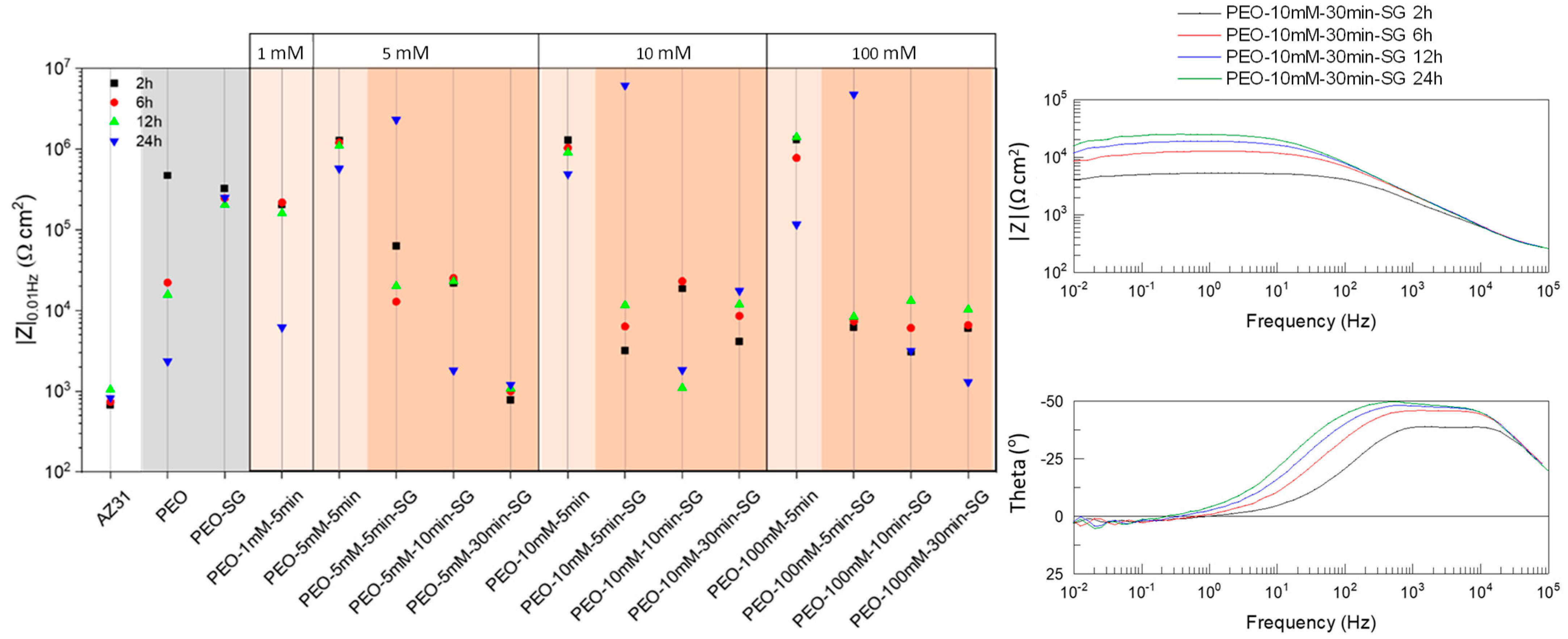
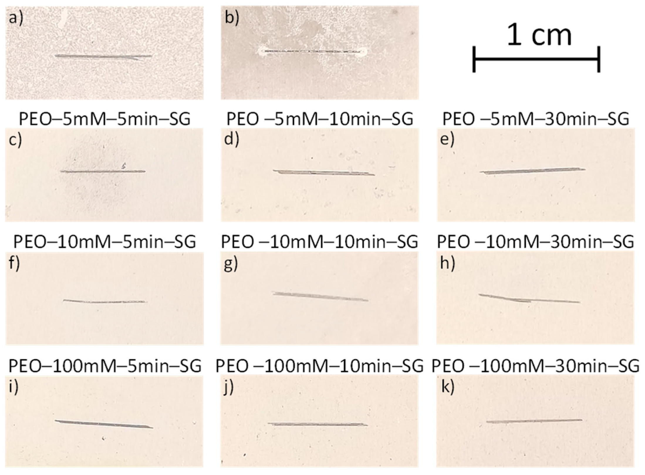
3.1.1. Optimization of Inhibitor Post-Treatment

After selecting 8HQ as the most promising inhibitor, several coating systems were outlined for further optimization. Initially, different concentrations of 8HQ (1, 5, 10, and 100 mM) were examined for the immersion post-treatment. Then, various hybrid PEO/sol–gel systems were evaluated, involving alterations in both the inhibitor concentration and post-treatment time (refer to Table 2) [45,46,47,48].
The EIS screening results are presented in Figure 1. All the combinations yielded higher impedance values than the bare alloy. The standalone PEO exhibits an impedance modulus two orders of magnitude higher than that of the substrate. However, its protective effect diminishes rapidly over time, reaching a modulus similar to that of the alloy after 24 h. In contrast, the hybrid system (PEO–SG) shows an initial impedance slightly lower than that of PEO, yet the response remains nearly constant with time. This long-term protection is attributed to the sealing of defects in the PEO coating [27]. The slightly lower impedance, in comparison to the PEO coating without sealing, may be linked to the partial dissolution of the ceramic coating induced by the slightly acidic conditions of the sol–gel precursor (pH 2).
The impregnation with 8HQ through the immersion post-treatment improved the performance of the PEO coating, most likely due to the formation of insoluble Mg(8HQ)2 deposit [49]. The sole exception was observed with the 1 mM solution, revealing a lower impedance value. This discrepancy may be attributed to insufficient Mg(8HQ)2 precipitation and potential degradation of the PEO coating in the post-treatment solution (pH 10).
Contrary to expectations, the application of sol–gel on top of the post-treated PEO coating resulted in lower impedance values than the reference PEO–SG film for all the tested combinations. The potential causes for this outcome are diverse. For instance, 8HQ–rich precipitates may disrupt the continuity of the sol–gel film. Additionally, the formation of Si–O–M bonds in the PEO/sol–gel interface could be influenced in the presence of 8HQ, leading to a reduction in the penetration of the sol–gel layer [45]. However, it is noteworthy that some coating systems reveal an increase in the modulus with prolonged immersion time. This improvement suggests active protection and recovery of the corrosion protection.
Except for the PEO–1 mM–5 min specimen, no significant differences are observed among the investigated hybrid PEO/inhibitor/SG systems. Therefore, all the full systems with inhibitor concentrations of 5, 10, and 100 mM were chosen for further evaluation.

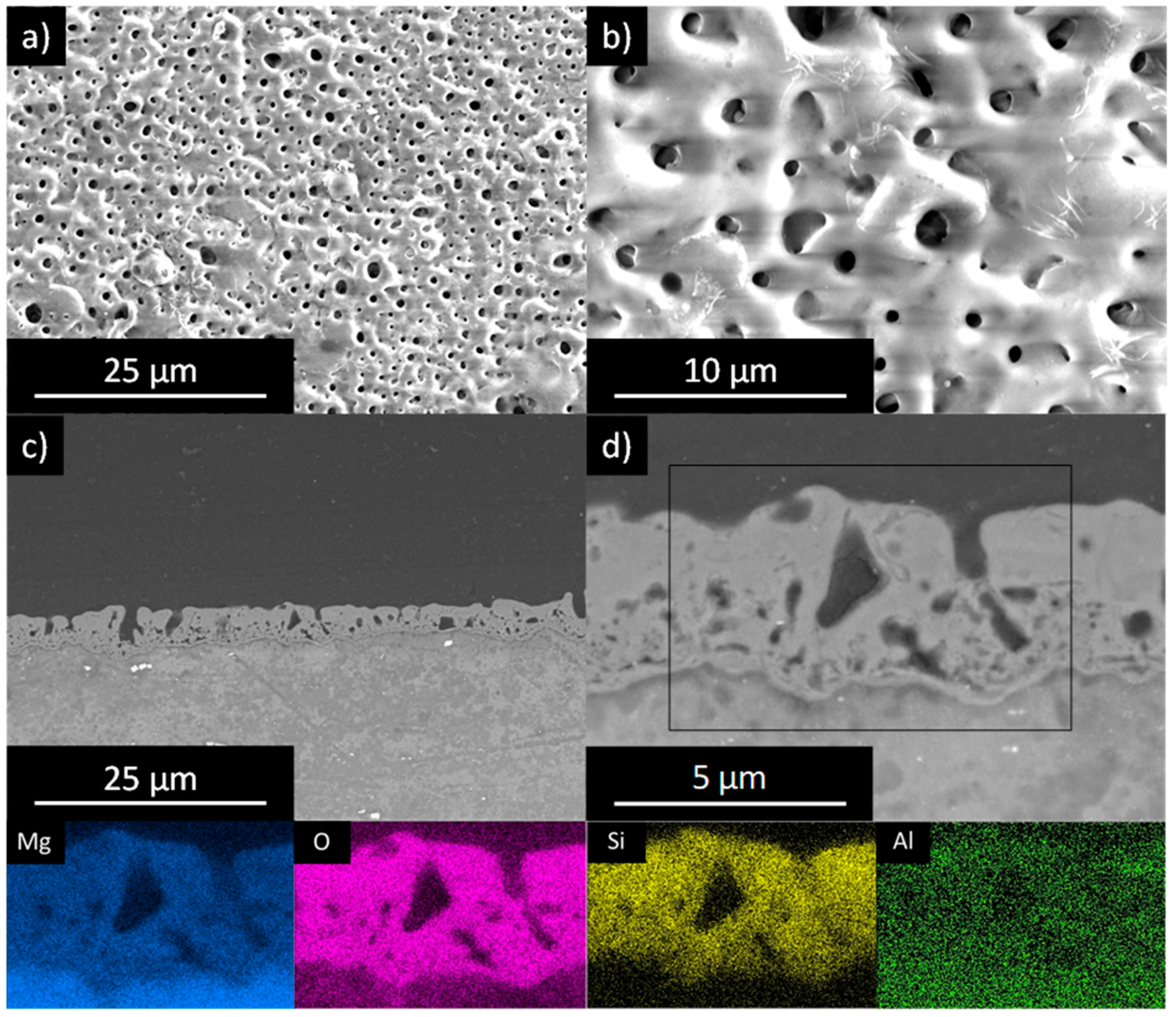
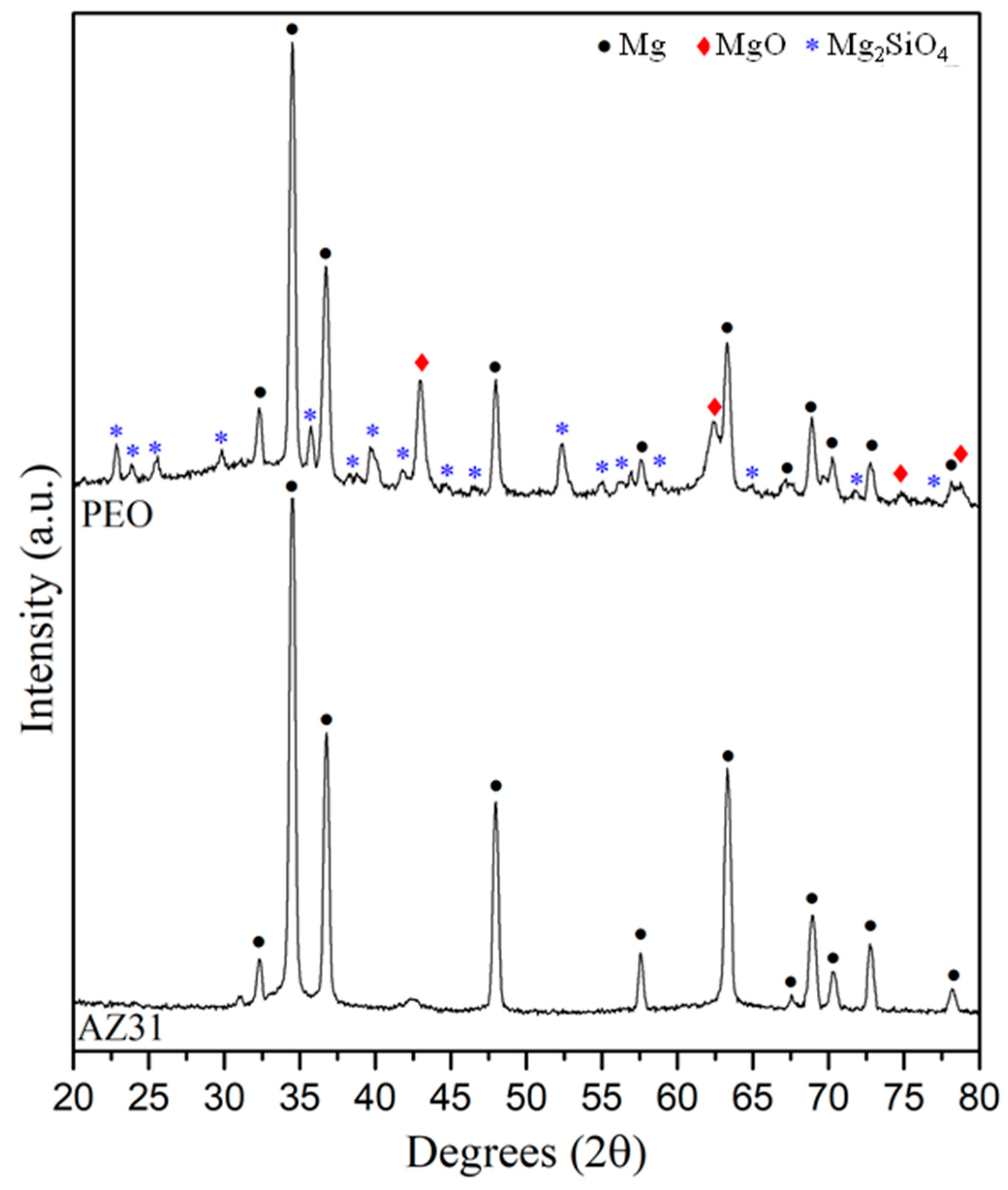
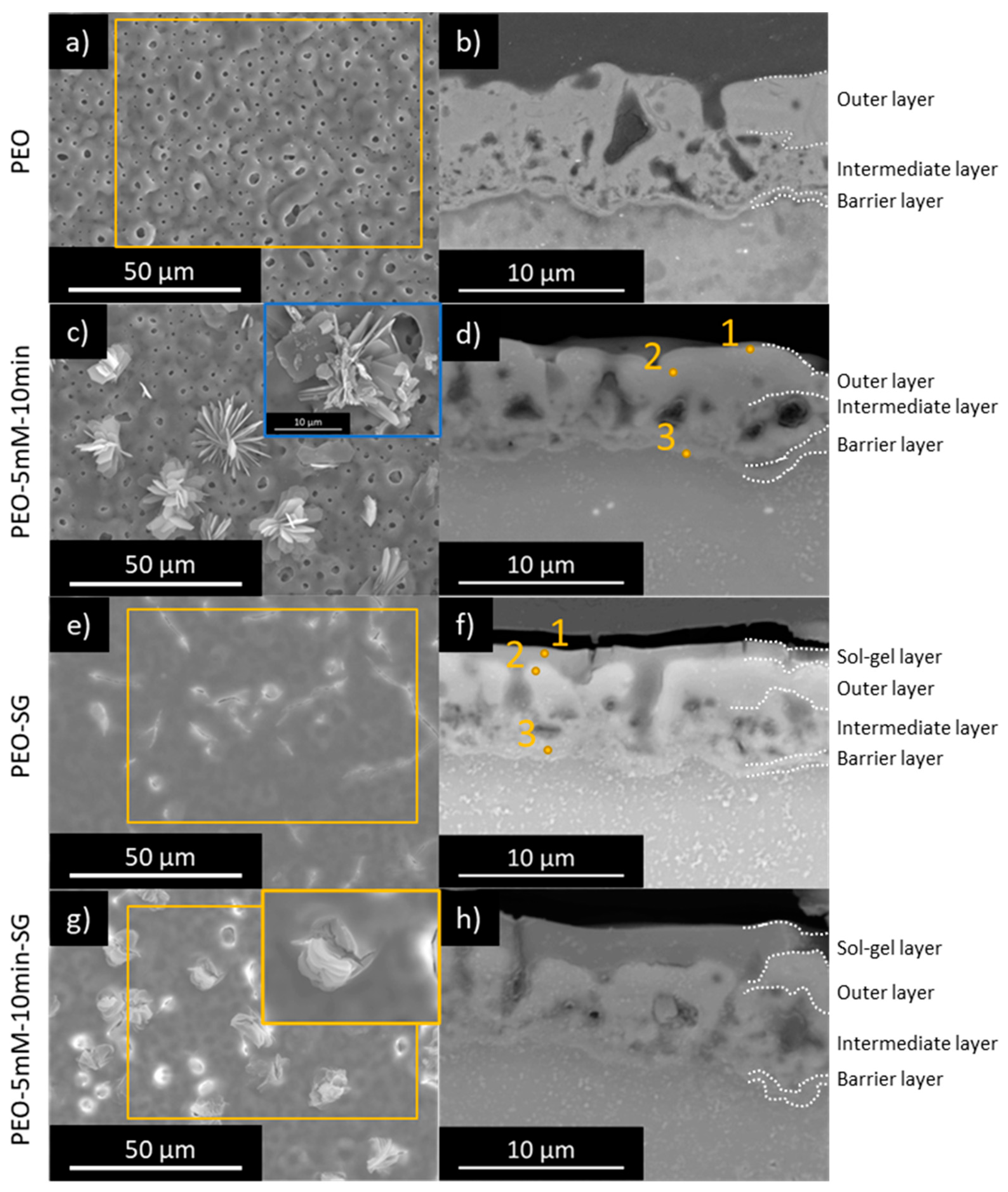
3.1.2. Coating Morphology and Composition

FTIR, SEM/EDS, and XRD analyses were employed to characterize the hybrid PEO/sol–gel systems, both with and without inhibitor impregnation, following the PEO processing. It is important to note that only representative systems were examined.
Figure 2 and Table 3 display the FTIR results of 8HQ powder, PEO–8HQ, PEO–SG, and PEO–8HQ–SG coatings [50,51,52]. In the spectrum of a representative specimen (PEO–5 mM–10 min), bands corresponding to 8HQ are still evident, indicating successful incorporation onto the surface (Figure 2b). However, a notable difference is observed; the 3150 cm−1 band associated with the phenol group vanishes due to the formation of metal complexes between 8HQ and Mg2+ [50]. It is important to note that the spectrum now exhibits bands originating from the PEO layer. The most distinct bands include the one at 3311 cm−1, attributed to ν(H–O), indicating hydration of the outermost region of the PEO layer. Additionally, several signals are observed related to Si–O–Si (1493–960, 960–724 cm−1) and Si–O–Mg bonds (<700 cm−1), indicating the incorporation of silicate from the electrolyte during PEO processing [27,53,54,55].
The spectra obtained for the PEO–SG and PEO–8HQ–SG coatings reveal characteristic bands of sol–gel layers. Signals at 3100–3600 cm−1 and 1585 cm−1 correspond to vibrations of the ν(H–O) bonds, originating from the Si–OH groups in the sol–gel layer and absorbed water molecules [27,50,51]. The intensity of these bands increases with the number of polar groups, serving as an indicator of the level of sol–gel polymerization. Vibrations of ν(C–H) bonds at 3000–2824 cm−1 correspond to the –CH3 and –CH2 groups from the GPTMS precursor. Notably, there is an increased intensity of the Si–O–Si and Si–O–M signals which come from both the PEO and sol–gel layers. The intensity of the band centred at ~1034 cm−1 is generally associated with asymmetric Si–O–Si vibrations, indicative of correct sol–gel formation.
It is important to mention that the inhibitor post-treatment with 8HQ leads to less pronounced Si–O–Si and Si–O–Mg bands for the hybrid PEO–8HQ–SG system. Therefore, it can be deduced that the 8HQ post-treatment interferes with the sol–gel process: the hydrolysis and condensation reactions are restricted, limiting the formation of a 3D network. Very few studies have investigated the impact of an intermediate post-treatment step on sol–gel sealing of PEO coatings [56,57,58], numerous examples exist where species incorporated in the sol–gel affect the degree of polymerisation associated with the inorganic and organic components [27].
Before discussing the SEM micrographs of the hybrid systems, the stand-alone PEO coating is presented first. SEM images of the surface of the PEO-coated AZ31 Mg alloy are presented in Figure 3 alongside the EDS maps. The unsealed coating reveals a crater-like morphology, with microcracks and micropores concentrated at the sites of the discharge channels, which formed due to residual stresses and gas evolution during coating formation (Figure 3a,b).
Cross-sectional micrographs (Figure 3c,d) reveal a well-defined barrier layer in combination with a thicker and porous outer layer (thickness 7.3 ± 0.4 µm). The EDS Si map of the PEO layer displays a significant contribution from Si, which is expected as the PEO coating was produced in an alkaline–silicate electrolyte [59,60,61]. The outer regions of the coating exhibit some Al enrichment, originating from the substrate.
The XRD results of the unsealed PEO coating (Figure 4) indicate the presence of magnesium oxide (MgO, JCPDS 75-1525) and forsterite (Mg2SiO4, JCPDS 34-0189). Crystalline phases of aluminium (e.g., MgAl2O4) were not detected. Therefore, the aluminium detected in the coating is primarily in the form of amorphous phases or as a dopant in the aforementioned compounds. The peaks corresponding to magnesium originate from the substrate (Mg, JCPDS 35-0821), a result of X-ray penetration.
Comparative SEM micrographs of the PEO-coated AZ31 alloy without and with post-treatment and sol–gel sealings are depicted in Figure 5, including planar and cross-view micrographs. Following a 10 min post-treatment, the surface of the PEO coating shows flakes of 8HQ complexes with two distinct morphologies (Figure 5c); (i) agglomerates of small flakes deposited on the flat surface of the PEO layer, surrounding smaller pores; and (ii) large flakes near bigger pores, resembling the morphology observed in Figure S2. No flakes were found in the cross-sectional micrographs, presumably washed away during cross-section preparation. Cross-view examination suggests a slight dissolution of the PEO coating after the inhibitor post-treatment (PEO 7.3 ± 0.4 µm vs. PEO–5 mM–10 min 6.7 ± 0.3 µm, Figure 5b,d).
The variation in the size of the flakes is attributed to the availability of Mg2+ ions. The dissolution of Mg is presumed to be more substantial within the pores, supplied by the substrate and PEO layer, leading to the formation of larger flakes. EDS analysis indicates that these flakes show elevated levels of C, O, and Mg, suggesting the formation of Mg(8HQ)2. These observations align with the findings of Vaghefinazari et al. [45], who reported the formation of Mg(8HQ)2 on a bare substrate exposed to a solution containing 8HQ.
Figure 5e reveals that the sol–gel sealing forms a uniform layer (1.8 ± 0.5 µm) that effectively fills the pores and cracks in the PEO layer. However, some surface defects, primarily cracks resulting from dehydration of the sol–gel layer during curing, are observed. These cracks are also visible in the cross-view (Figure 5f). The thickness of the PEO coating decreased to 5.4 ± 0.5 µm due to the acidic conditions during sol–gel sealing. The overall thickness of the PEO–SG system was 6.4 ± 0.2 µm. It is noteworthy that the inner barrier layer of the PEO coating remains intact.
Micrographs of specimens with a sol–gel layer on top of a PEO layer post-treated with 8HQ are presented in Figure 5g,h. Similar to the observations on the PEO–SG surface, the sol–gel layer fills the pores and cracks in the PEO layer; however, here, the Mg(8HQ)2 deposits emerge from the surface of sol–gel layer at certain points. Dehydration cracks in the sol–gel layer are also noticeable. Once again, no Mg(8HQ)2 flaky deposits are observed in the cross-view, but minor bulky precipitates are visible inside the pores. The overall thickness increases to 8.2 ± 0.4 µm, with the sol–gel layer being thicker than in previous cases (2.9 ± 0.2 µm). The sol–gel thickening is attributed to the increase in surface roughness due to the presence of the Mg(8HQ)2 precipitates. It is noteworthy that the PEO layer exhibits some dissolution (5.5 ± 0.7 µm), with the intermediate layer being less evident than in the PEO and PEO–SG systems (see labels in Figure 5).

3.1.3. Corrosion Test: Immersion Tests

Figure 6 shows digital macrographs of the PEO–8HQ–SG specimens with an artificial scribe after 14 days of immersion in a 0.5 wt.% NaCl solution, with PEO and PEO–SG specimens included as references. The stand-alone PEO coating reveals corrosion across the entire surface (Figure 6a), while the PEO–SG system demonstrates slightly improved performance. Nevertheless, there are noticeable signs of corrosion adjacent to the scratch and some localized damages away from it.
The PEO–8HQ–SG systems reveal significantly less corrosion damage than the reference coatings (Figure 6c–k), although the 5 mM 8HQ post-treatments show some corrosion around the scratch. This aligns with the EIS results, where post-treatments with low 8HQ concentration displayed a lower modulus of impedance after 24 h (e.g., PEO–5 mM–5 min–SG; 1.1 × 10⁶ Ω cm−2 vs. PEO–10 mM–5 min–SG; 5.1 × 10⁶ Ω cm−2). The PEO–10 mM–30 min–SG coating stands out as one of the best performers and was selected for further characterization (Figure 6h). Therefore, these results suggest a positive effect of increasing the 8HQ concentration. It is proposed here that the dissolution of Mg(8HQ)2 flakes and their redeposition in regions with high pH (above 7, [45]) provides a self-healing ability, thereby enhancing the long-term corrosion resistance of the hybrid systems.
SEM/EDS results of the scribed systems after 14 days of immersion in 0.5 wt.% NaCl are presented in Figure 7 and Table 5. PEO–10 mM–30 min–SG was selected as a representative of PEO–8HQ–SG systems due to its superior corrosion performance.
The scratch in the PEO specimen shows voluminous corrosion products rich in O and Mg (Figure 7a, Table 5). As illustrated in Figure 7b, typical PEO micropores are no longer visible due to coating hydration, with some cracks formed as a consequence of partial dehydration. The cross-sectional view reveals that the corrosion attack is quite deep, especially at the centre of the defect where small pits are revealed (inset in Figure 7c). The incorporation of F and Si in these corrosion products is noteworthy. These elements can only be released from the PEO coating. It is believed that SiO32− anions originating from the dissolution of the PEO coating combine with Mg2+ in the solution, forming precipitates such as MgSiO3. Despite these self-repairing properties, the level of protection is insufficient, and some of the non-scribed areas also display corrosion damage, indicating failure of the inner barrier layer (Figure 7d).
In comparison with the stand-alone PEO coating, the PEO–SG system shows a lesser amount of corrosion products (Figure 7e–h). Corrosion products are primarily present at the artificial defect and its surroundings, with the cracked appearance of the sol–gel layer being particularly noticeable. The cross-sectional view of the defect (Figure 7g) reveals a small amount of corrosion products within the scribe. The EDS analysis at the centre of the scribe also shows some Si, which can originate from either the PEO coating or the sol–gel layer.
The PEO–10 mM–30 min–SG demonstrates the best corrosion behaviour, as evidenced by the shallow depth of the scratch (Figure 7i–l). The initial depth of the scratch is 20 ± 2 µm and it reaches values of 49 ± 5 µm, 31 ± 2 µm and 22 ± 2 µm for PEO, PEO–SG, and PEO–10 mM–30 min–SG, respectively, after 14 days of immersion. The presence of C and O along with Mg in EDS area 1 may be indicative of the presence of Mg(8HQ)2 (Table 5).

3.1.4. Contact Angle

The contact angle measurements were conducted to evaluate the hydrophilicity/-phobicity of the developed coatings (Table 6 and Figure S3). All the coatings show hydrophilic behaviour with values below 66°. Minor differences are observed between the PEO and the sol–gel sealed samples. The inherent porosity of the PEO coating is strongly correlated with the obtained contact angle value, and its tendency to hydrate also contributes to this behaviour. The sol–gel layer significantly reduces the contribution of surface defects; therefore, the hydrophobic character is mostly related to the chemistry of the sol–gel surface rather than its roughness.
According to SEM and FTIR results, the PEO–8HQ–SG specimens should be more hydrophilic due to the following two factors: (i) disrupted sol–gel layer in the presence of Mg(8HQ)2 flakes; and (ii) a lower degree of sol–gel polymerization in the presence of 8HQ, resulting in an increased number of hydrophilic silanol groups and, therefore, increased hydrophilicity [27,62]. However, as shown in Table 6, the difference between specimens with and without treatment is not significant.

3.2. Results on PEO/Sol–Gel(Inhibitor) Systems

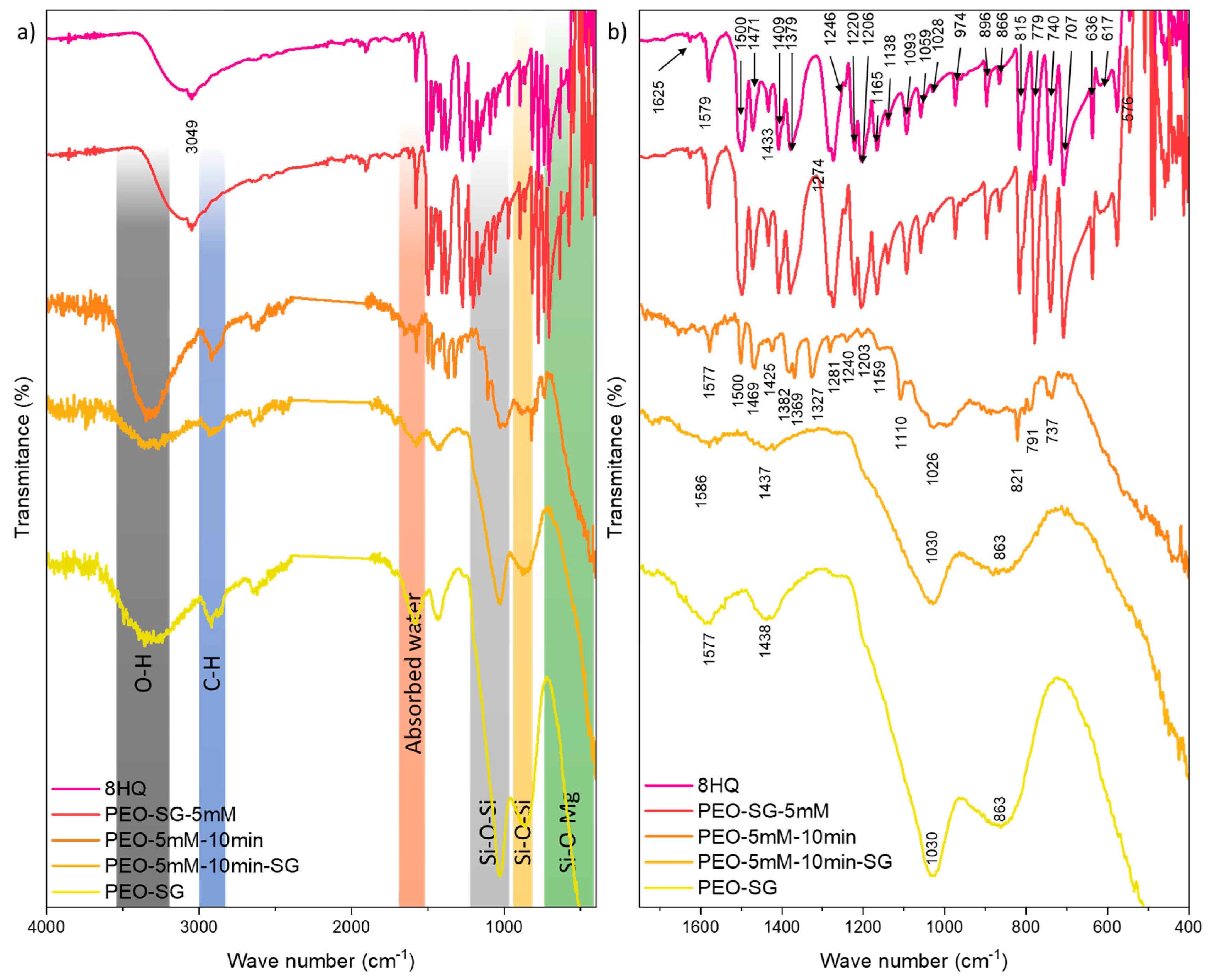
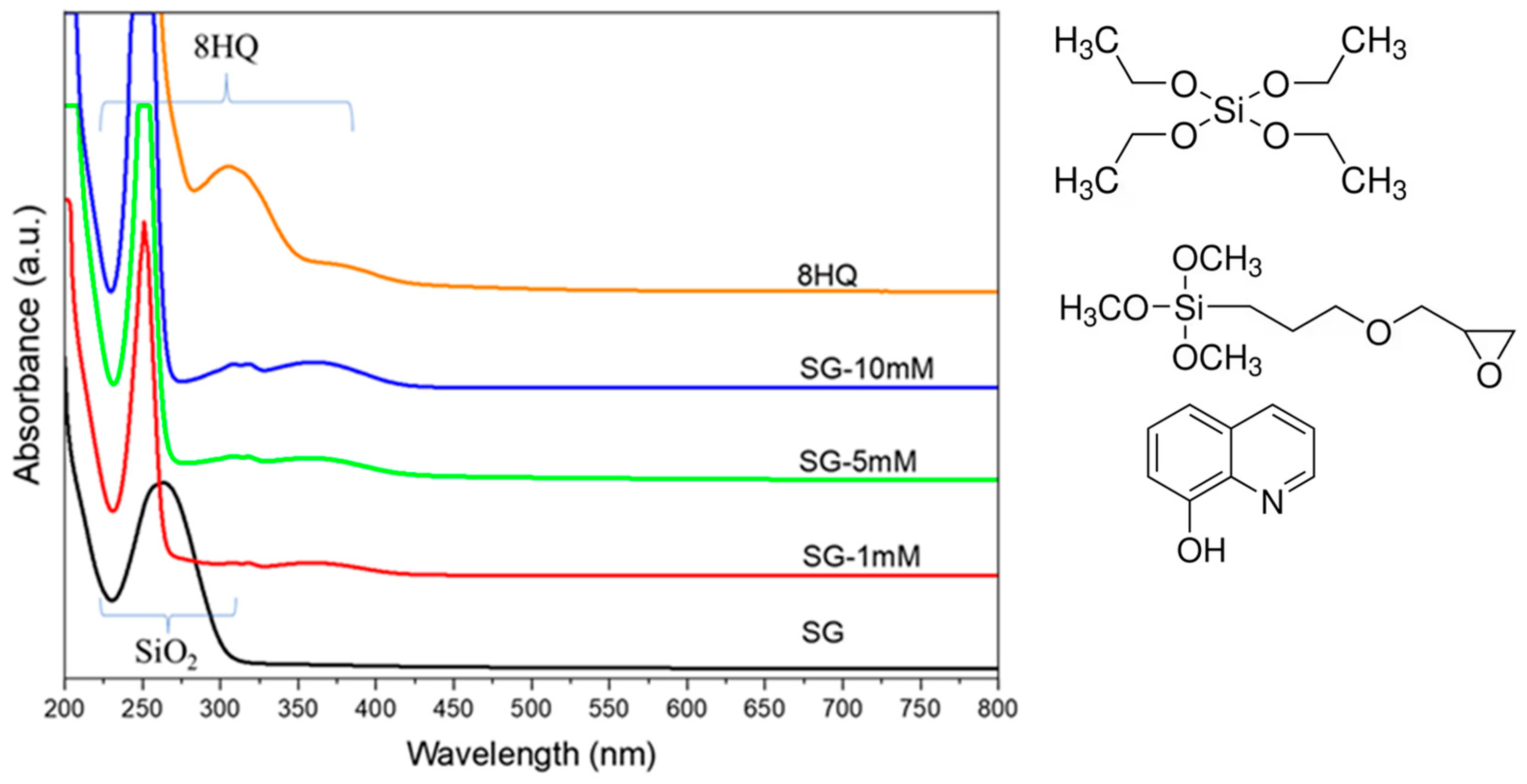
3.2.1. Sol–Gel/8HQ Precursors

Sol–gel precursors with varying amounts of incorporated 8HQ corrosion inhibitor were prepared for sealing the PEO coating on the AZ31 alloy. The PEO processing was identical to that already described. Therefore, the inhibitor loading approach in this hybrid PEO/sol–gel system differs from that of the previous section, where the inhibitor was incorporated after PEO and before the sol–gel sealing.
The inhibitor was incorporated into the precursor by dissolving 8HQ in the aqueous solution, constituting 58% of the sol–gel. Figure 8 depicts the rheological characterization of the sol–gel precursors before polymerization. The shear rate increases with the shear stress with a constant slope for all cases, indicating Newtonian behaviour. The presence of 8HQ causes a slight reduction in viscosity, with the 10 mM concentration yielding the lowest values. The viscosity values in mPa·s were as follows: 3.87 ± 0.02, 3.74 ± 0.02, 3.74 ± 0.02, and 3.71 ± 0.02 for SG, SG–1 mM, SG–5 mM, and SG–10 mM, respectively. These values suggest that the addition of 8HQ may slightly facilitate the penetration of the sol–gel precursor into the PEO coating.
Figure 9 presents the UV–visible spectra of the sol–gel solutions with and without 8HQ. It is important to note that a 10 times dilution in deionized water was used to avoid detector saturation. The 8HQ (0.05 M) aqueous solution is included as a reference, showing a saturated peak at 250 nm and an absorption maximum at 305 nm, characteristic of the neutral prototropic species of 8HQ in water [38]. When 8HQ is incorporated into the acidic sol–gel precursor (pH 2 after hydrolysis) a new broad band emerges at 358 nm, corresponding to the lowest electronic transition of the acidic prototropic species of 8HQ (both O and N are protonated). The intensity of this band is higher for the precursor with the highest amount of 8HQ. Therefore, UV–Vis spectra confirm the presence of 8HQ in the sol–gel precursor.
The SG solution without the inhibitor exhibits an absorption maximum at 263 nm, attributed here to electronic transitions of SiO2 [63] due to partial polymerization of the precursor. Specifically, the absorption band is related to non-bridging oxygen hole centres [64].

3.2.2. Optimization of Sol–Gel Precursors Loaded with Inhibitor

Figure 10 depicts the impedance modulus of the examined coatings at 0.01 Hz in 0.5 wt.% NaCl up to 48 h of immersion, with reference impedance results for AZ31, PEO and PEO–SG included. After 2h of immersion, PEO–SG–8HQ specimens exhibit a lower impedance modulus than the inhibitor-free PEO–SG system. Notably, the impedance is lowest for the highest 8HQ concentration (PEO–SG–10 mM), with decreasing values for increasing 8HQ concentration in the sol–gel film. Despite this negative effect of 8HQ incorporation, PEO–SG–1 mM and PEO–SG–5 mM specimens demonstrate improved performance after 24 h (e.g., |Z| > 107 Ω cm2 for PEO–SG–1 mM).
These findings suggest that 8HQ has conflicting effects when integrated into the sol–gel precursor. On one hand, it impedes sol–gel polymerization (see Section 3.2.3), decreasing the barrier effect against the corrosive medium. On the other hand, when added in a small concentration (1 mM), 8HQ significantly improves the impedance response after extended immersion times. The positive effect is likely associated with the precipitation of complexes formed between the 8HQ molecules released from the sol–gel layer and the Mg2+ ions originating from the corroding substrate.

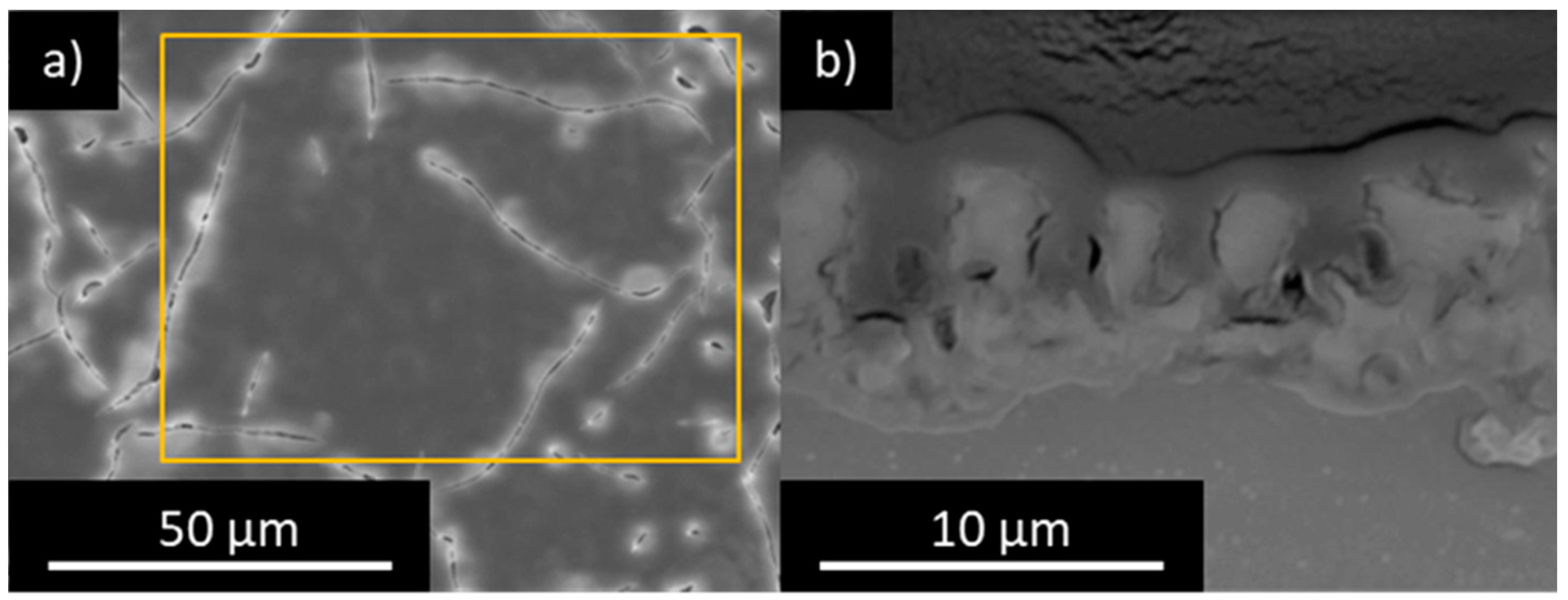
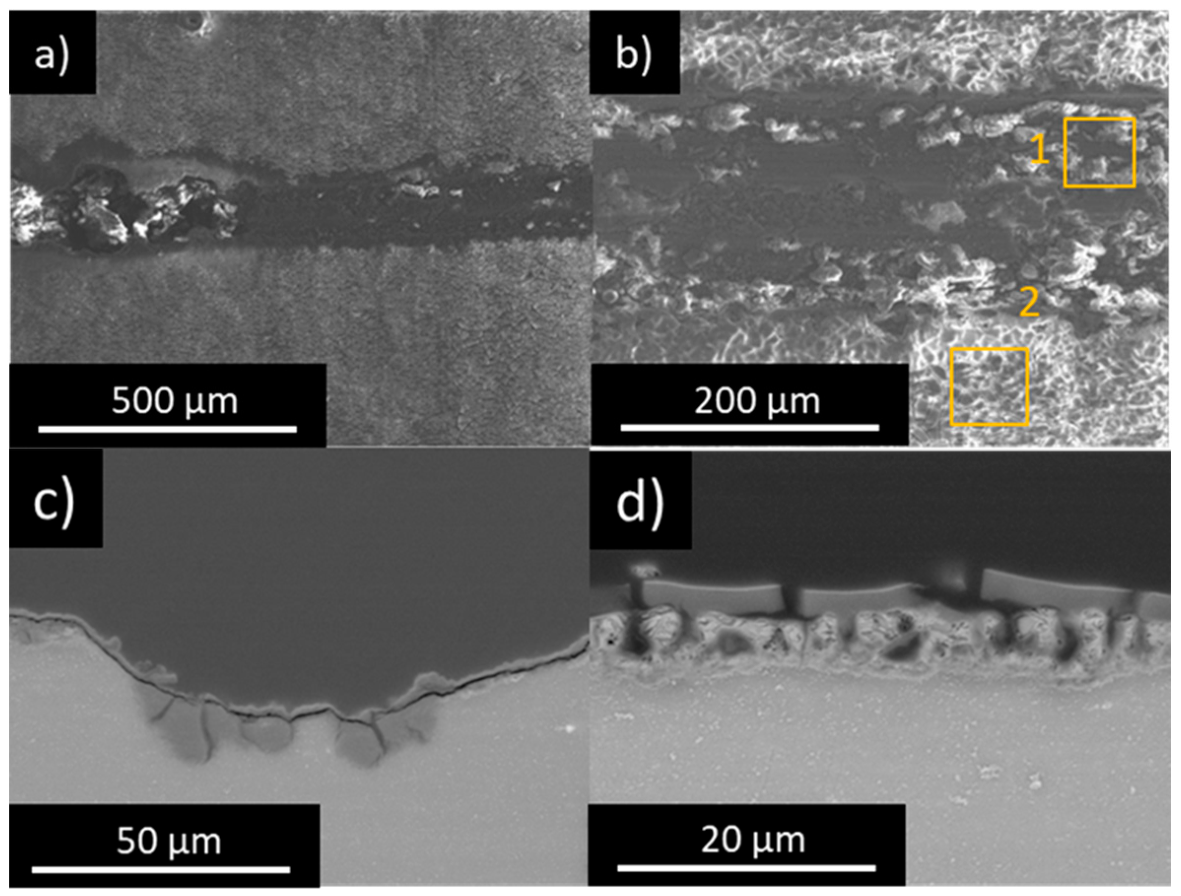
3.2.3. Coating Morphology and Composition

FTIR results of PEO–SG–8HQ systems are depicted in Figure 11 and Table 7, with the spectrum of 8HQ powder included for reference. Si–O–Si bonds show their characteristic signals at 1493–960 and 960–724 cm−1 [27]. Once again, the prominent band at ~1034 cm−1, associated with asymmetric vibrations, signifies successful sol–gel polymerization. Comparatively, the presence of 8HQ results in less intense Si–O–Si signals, suggesting that 8HQ has a detrimental effect on the polymerization process. Similarly, the band below 700 cm−1, corresponding to Si–O–M bonds, is more intense for PEO–SG, indicating a better interaction between the PEO and the inhibitor-free sol–gel layer. Note that bands corresponding to the 8HQ molecule are nearly invisible when incorporated into the sol–gel layer.
Surface and cross-sectional SEM micrographs for the PEO–SG–1 mM specimen, representative of the studied systems, are presented in Figure 12. Some cracks are evident in the sol–gel layer (Figure 12a), but the porosity of the PEO layer is almost completely sealed (Figure 12b). The thickness of the sol–gel film is 2.1 ± 0.7 μm, as measured with the eddy current method, without significant influence from 8HQ. The EDS analysis of the sol–gel layer is consistent with previous results, but there is a relatively high amount of C, indicative of 8HQ incorporation in the sol–gel layer.

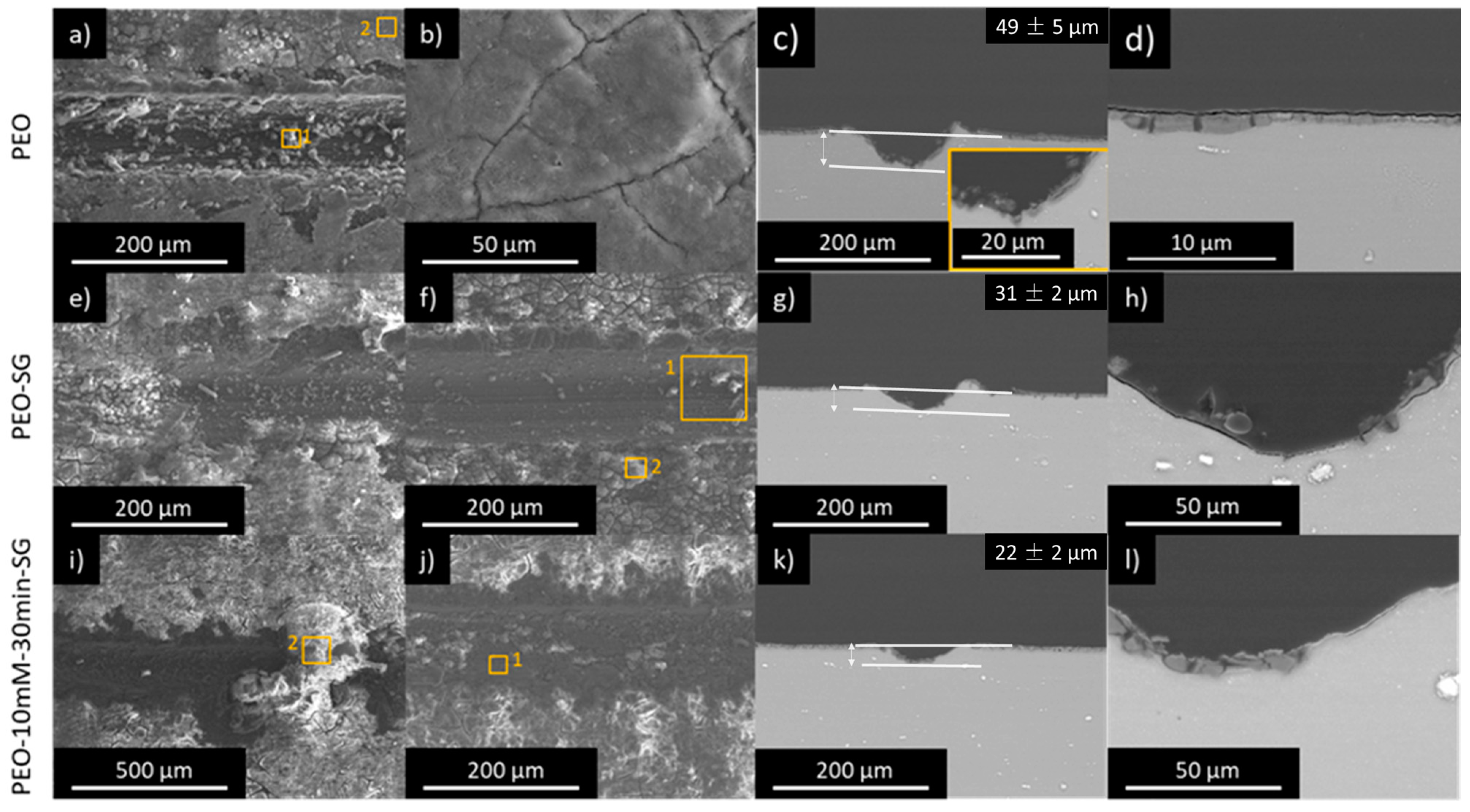
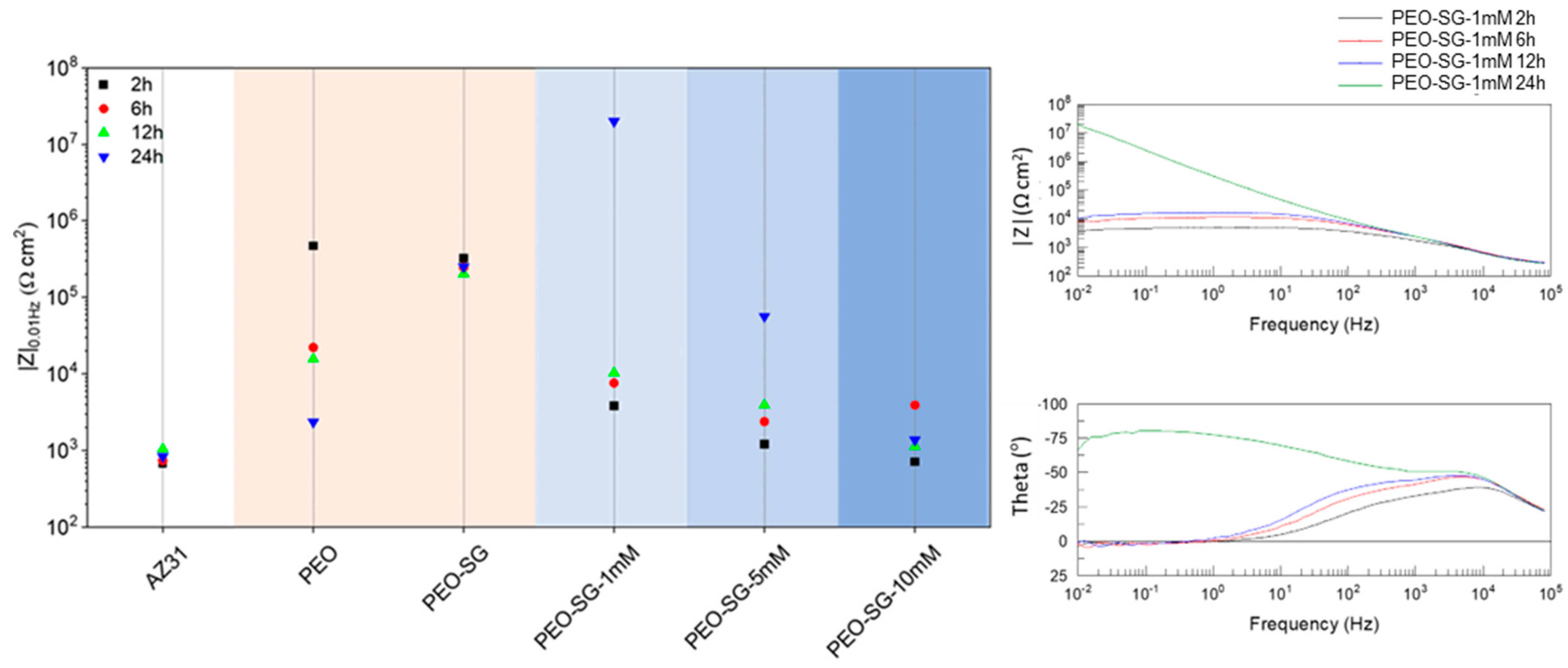
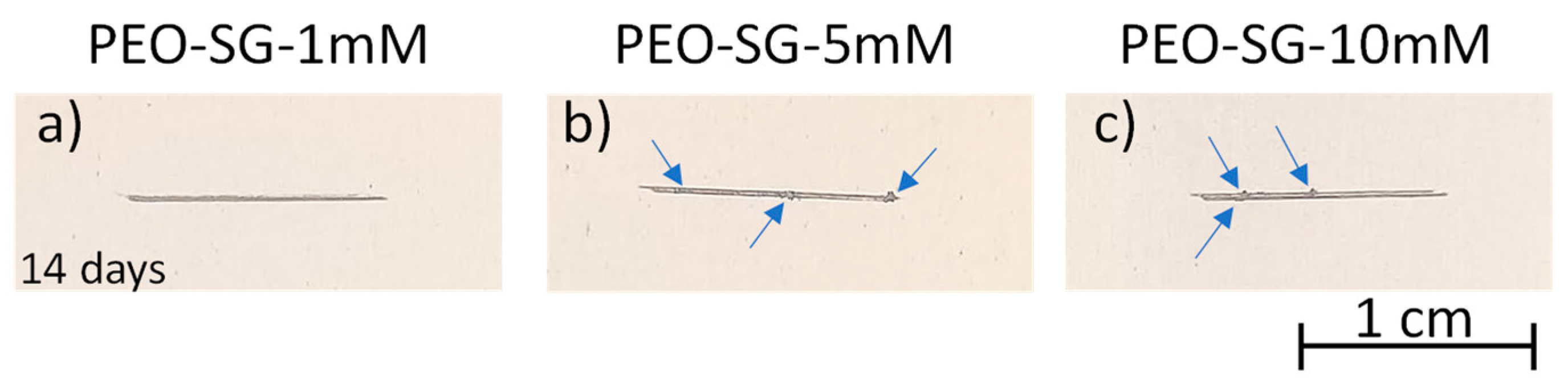
3.2.4. Corrosion Test: Immersion Test

The surface appearance of PEO–SG–8HQ systems with an artificial scribe after 14 days in 0.5 wt.% NaCl is presented in Figure 13. Overall, the specimens show much better corrosion performance than PEO and PEO–SG (see Figure 6a,b). However, some small corrosion spots are visible at the scratch for the PEO–SG–5 mM and PEO–SG–10 mM specimens. Therefore, the addition of 8HQ into the sol–gel precursor improves the long-term corrosion resistance of hybrid PEO/SG systems, although their performance is slightly compromised when the concentration of 8HQ is above 1 mM.
The PEO–SG–1 mM specimen, which combines the highest |Z| value with best surface appearance after the scribe test, was selected for SEM/EDS examination (Figure 14 and Table 8). As shown in the plan-view, the scribe shows some corrosion products and there is cracking of the sol–gel layer, attributed to water permeation and hydrolysis of the Si–O–Si bonds [65]. (Figure 14a,b). However, the depth of the attack is significantly less than that of the inhibitor-free systems (PEO, PEO–SG in Figure 14), being very similar to the original depth of the defect (~20 µm, Figure 14c). In the regions away from the scratch, it can be seen that the cracks penetrate the entire sol–gel thickness, although the PEO coating remains relatively unaffected, with only some signs of hydration (Figure 14d).
EDS analysis on the scribe’s surface shows a relatively high level of O, suggesting the formation of magnesium hydroxide as the main corrosion product. There is also some Si and F, which can originate from chemical dissolution of the PEO and/or sol–gel films (in case of Si), and C, although no Mg(8HQ)2 flakes were detected on the surface of the scratch.

4. Discussion

PEO coatings are known to be susceptible to corrosion in saline environments due to the limited protection provided by MgO and the absence of self-healing ability. To address this drawback, various strategies have been employed to incorporate inhibitors into PEO coatings. This study explores two approaches: inhibitor impregnation of the PEO layer before sol–gel sealing and the modification of the sol–gel precursor with the organic inhibitor 8HQ. The selection of 8HQ was made following an initial screening process using EIS tests.
The inhibitory effect of 8HQ is linked to the formation of insoluble metal chelates on the surface [29]. This mechanism has been demonstrated on materials such as aluminium [65] and copper [37]. On magnesium surfaces, Mg(8HQ)2 precipitates in alkaline solutions in the form of large flakes [45]. In the present study, these flakes were clearly visible on the surface of AZ31 alloy after a 14-day immersion in a 0.5 wt.% NaCl solution containing 0.05 M 8HQ. A recent study by Vaghefinazari et al. [45] also highlighted the formation of Mg(8HQ)2 flakes on the surface of a PEO-coated AZ21 alloy, leading to improved corrosion resistance. Precisely, in the present work, the immersion post-treatment approach was successfully applied to incorporate 8HQ into the so-called hybrid PEO–8HQ–SG systems.
The second approach for incorporating 8HQ, denoted as PEO–SG–8HQ, aligns with findings from earlier studies [29], where sol–gel formulations doped with 8HQ demonstrated enhanced corrosion resistance on AZ31. The innovation in this study lies in the combination of the barrier properties of the PEO layer, the sealing effect of the sol–gel, and the active protection imparted by the 8HQ inhibitor. In this context, 8HQ is proposed to function through a release–precipitation mechanism, effectively impeding corrosion in areas where damage has occurred.
In the present study, a comparison between the PEO–8HQ–SG and PEO–SG–8HQ strategies revealed that, irrespective of the approach, the incorporation of 8HQ improved the long-term corrosion resistance. This effect was particularly evident in scribed specimens, indicating an active protection mechanism in the presence of 8HQ. Both PEO–8HQ–SG and PEO–SG–8HQ systems demonstrated similar outcomes, displaying minimal corrosion depth at the scratch site after 14 days of immersion in 0.5 wt.% NaCl. The influence of variables such as inhibitor post-treatment time and 8HQ concentration did not exhibit a clear trend. Nonetheless, the PEO–100 mM–30 min–SG and PEO–SG–1 mM configurations emerged as among the top performers, considering EIS results and corrosion tests with scribed specimens. Additional research is needed to identify the advantages and disadvantages of the strategies under study. Specifically, the assessment should include parameters such as inhibitor release rate, compatibility with paints and inhibitor effectiveness when employed in conjunction with alternative sol–gel formulations.
Figure 15 shows the schematics illustrating the proposed protection mechanisms for the developed hybrid systems. In the case of the PEO–8HQ–SG combination, obtained through immersion post-treatment in an 8HQ solution followed by sol–gel sealing, a composite structure is formed, with flakes of Mg(8HQ)2 embedded in the sol–gel matrix and protruding at certain locations (Figure 15a). These areas exhibit greater heterogeneity and show the presence of small cracks. On the other hand, the PEO–SG–8HQ combination does not exhibit Mg(8HQ)2 flakes (Figure 15b). However, UV–visible and FTIR spectra provided sufficient evidence of successful incorporation of 8HQ into the sol–gel film. Remarkably, FTIR results indicated a lower degree of sol–gel polymerization and interaction between the sol–gel layer and the PEO coating when 8HQ was added to the precursor.
In light of the findings from this study, when mechanical damage occurs in PEO–8HQ–SG and PEO–SG–8HQ systems, the following steps are likely to take place:
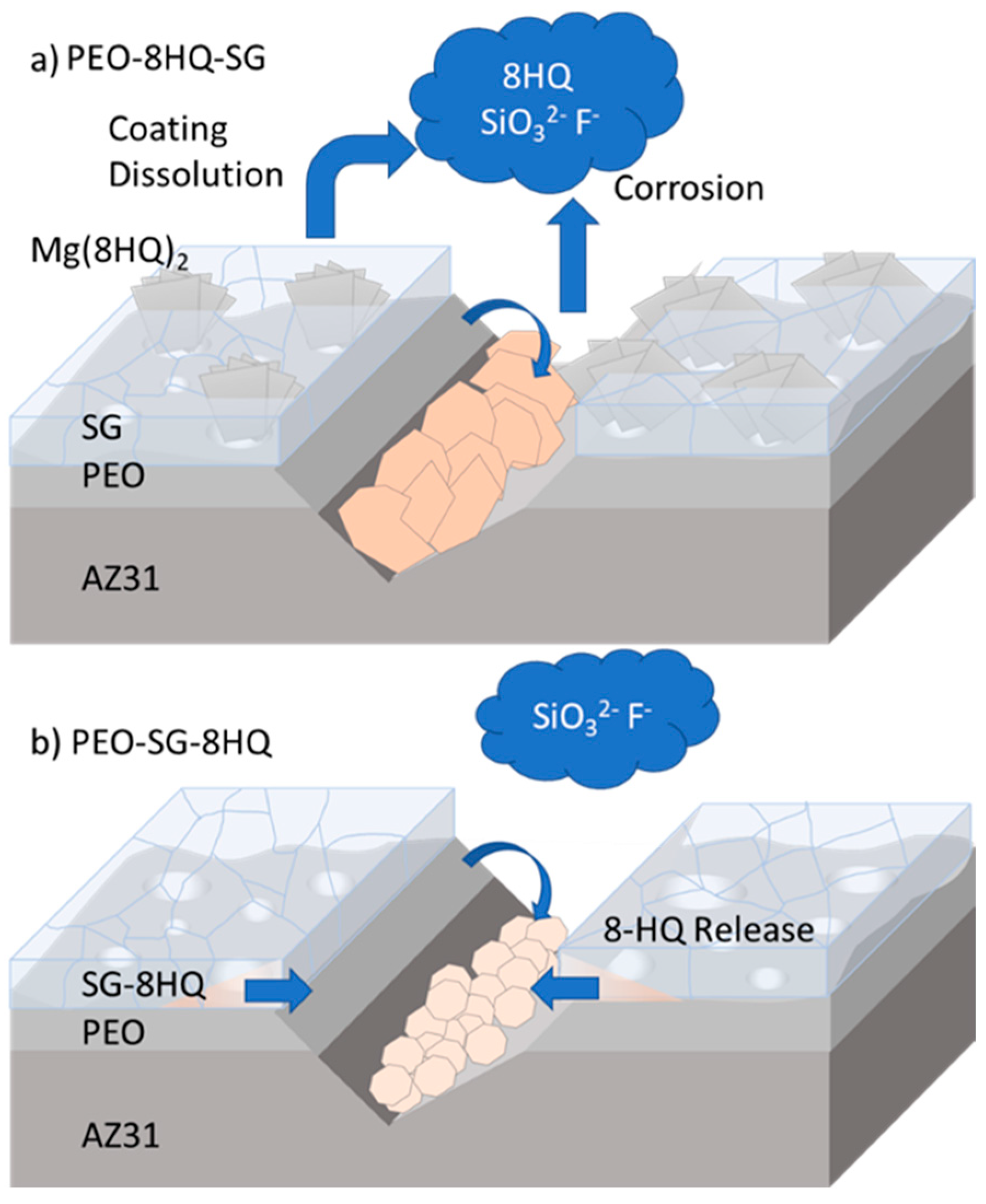
  • Corrosion occurs at the location of the scribe with liberation of Mg2+ ions.
M g ( s ) M g 2 + ( a q ) + 2 e
2.
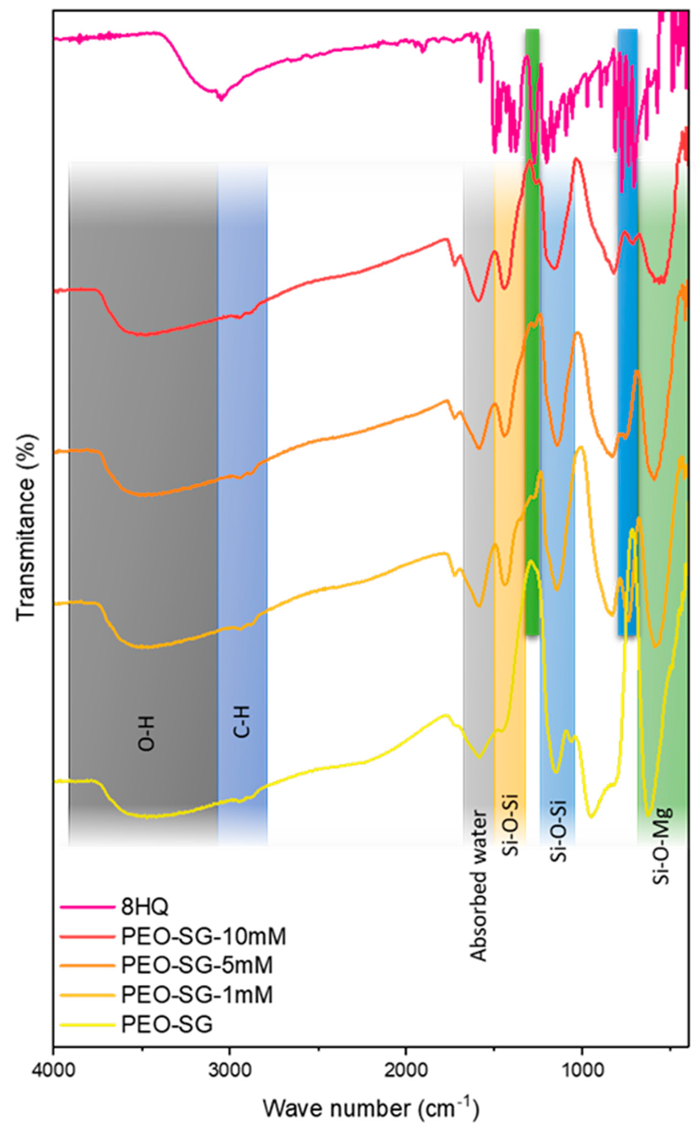
Water uptake and hydrolysis of the Si–O–Si bonds causes cracking of the sol–gel layer and Si release [66].
S i O 2 ( s ) + 2 H 2 O ( l ) S i ( O H ) 4 ( a q )
3.
Chemical dissolution of the PEO coating with liberation of SiO32−, Mg2+, and F ions occurs when acidic pH of the sol–gel solution penetrates across pores of the layer. Some dissolution is also expected to occur in the damaged regions next to the scratch. This chemical dissolution process is well documented in the literature [67,68].
M g O ( s ) + 2 H + ( a q ) M g 2 + ( a q ) + H 2 O ( l )
M g 2 S i O 4 s + 4 H + a q 2 M g 2 + a q + S i O 3 2 a q + H 2 O ( l )
4.
In neutral or slightly acidic conditions, 8HQ ions are released from the Mg(8HQ)2 flakes [29] in the PEO–8HQ–SG system and from the bulk of the sol–gel layer [69] in the PEO–SG–8HQ system. Subsequently, as the pH increases over the cathodic regions due to the water reduction reaction, 8HQ combines with Mg2+ and precipitates as Mg(8HQ)2. These precipitates remain insoluble under the highly alkaline conditions developed in the scratch region [45,70].
5.
The combination of Mg2+ with other species in the solution (SiO32−, F, OH) leads to the formation of additional precipitates, further contributing to the delay of the corrosion attack. This precipitation is more prominent at the location of the scratch due to a higher amount of Mg2+ ions and confinement of the solution. EDS analyses in this study have demonstrated the presence of Si and F on the surface of the scribe. However, additional studies are required to confirm the precipitation of Mg(8HQ)2 in the damaged areas, for example, through testing for longer immersion times.

5. Conclusions

Key conclusions drawn from the investigation into inhibitor loading on PEO/sol–gel systems include:
  • Hydrogen evolution tests identified 8HQ as the most effective organic corrosion inhibitor for the AZ31 alloy in a saline solution, operating through the formation of insoluble Mg(8HQ)2 flakes.
  • Successful incorporation of 8HQ inhibitor species into hybrid PEO/sol–gel systems was achieved through two strategies: (i) inhibitor post-treatment before sol–gel sealing (PEO–8HQ–SG); (ii) inhibitor loading into the sol–gel precursor (PEO–SG–8HQ).
  • The PEO–8HQ–SG system exhibited a composite structure with embedded Mg(8HQ)2 flakes in the SG film, while the PEO–SG–8HQ incorporated 8HQ into its structure, albeit with a reduction in the cross–linking of the sol–gel layer.
  • Both PEO–8HQ–SG and PEO–SG–8HQ systems demonstrated comparable results, displaying minimal depth of corrosion attack at the scratch location after 14 days of immersion in 0.5 wt.% NaCl. This improvement primarily stemmed from an active protection mechanism involving the release and precipitation of 8HQ species and other species (SiO32−, F).
  • Notably, the PEO–10 mM–30 min–SG and PEO–SG–1 mM coatings emerged as top performers in the tests involving EIS and immersion with scribed specimens.

Supplementary Materials

The following supporting information can be downloaded at: https://www.mdpi.com/article/10.3390/coatings14010084/s1. Table S1: Kinetic laws, with and without inhibitor, calculated from hydrogen measurements. Table S2: Results of the local EDS surface analysis of the coatings (at.%). Figure S1: Volume of hydrogen evolved from the cathodic reaction during immersion in 0.5 wt.% NaCl solution and surface appearance of the exposed area after the test. Figure S2: (a) Surface morphology of bare AZ31 exposed to 0.5 wt.% NaCl containing 8HQ after 14 days. A higher magnification view of the flakes is presented in (b). Marked areas corresponds to the EDS analysis collected in Table S2. Figure S3: Water contact angle measurements: (a) PEO, (b) PEO–SG, and (c–k) PEO–8HQ–SG.

Author Contributions

Conceptualization, B.P., E.M., M.-G.O., M.M. and R.A.; Formal analysis, B.P., M.M. and R.A.; Funding acquisition, M.-G.O., M.M. and R.A.; Investigation, B.P.; Methodology, B.P., M.-G.O., M.M. and R.A.; Project administration, M.-G.O., M.M. and R.A.; Resources, M.-G.O., M.M. and R.A.; Writing—original draft, B.P.; Writing—review and editing, E.M., M.-G.O. and R.A. All authors have read and agreed to the published version of the manuscript.

Funding

The authors gratefully acknowledge the support of PID2021-124341OB-C22 project (MCIN/AEI/FEDER, EU) and the Materials Institute of UMONS. M. Mohedano is grateful for the support of RYC-2017 21843.

Institutional Review Board Statement

Not applicable.

Data Availability Statement

All data presented in this work is available in Docta Complutense repository https://docta.ucm.es/handle/20.500.14352/16 (accessed on 5 December 2023).

Conflicts of Interest

The authors declare no conflicts of interest.

References

  1. Oak Ridge National Laboratory. Transportation Energy Data Book, 40th ed.; Oak Ridge National Laboratory: Oak Ridge, TN, USA, 2022. [Google Scholar]
  2. Demirci, E.E.; Arslan, E.; Ezirmik, K.V.; Baran, Ö.; Totik, Y.; Efeoglu, İ. Investigation of wear, corrosion and tribocorrosion properties of AZ91 Mg alloy coated by micro arc oxidation process in the different electrolyte solutions. Thin Solid Film. 2013, 528, 116–122. [Google Scholar] [CrossRef]
  3. Shang, W.; Chen, B.; Shi, X.; Chen, Y.; Xiao, X. Electrochemical corrosion behavior of composite MAO/sol–gel coatings on magnesium alloy AZ91D using combined micro-arc oxidation and sol–gel technique. J. Alloys Compd. 2009, 474, 541–545. [Google Scholar] [CrossRef]
  4. Guo, X.; Du, K.; Guo, Q.; Wang, Y.; Wang, F. Experimental study of corrosion protection of a three-layer film on AZ31B Mg alloy. Corros. Sci. 2012, 65, 367–375. [Google Scholar] [CrossRef]
  5. Chen, Q.; Zheng, Y.; Dong, S.; Chen, X.-B.; Dong, J. Effects of fluoride ions as electrolyte additives for a PEO/Ni-P composite coating onto Mg alloy AZ31B. Surf. Coat. Technol. 2021, 417, 126883. [Google Scholar] [CrossRef]
  6. Wierzbicka, E.; Vaghefinazari, B.; Lamaka, S.V.; Zheludkevich, M.L.; Mohedano, M.; Moreno, L.; Visser, P.; Rodriguez, A.; Velasco, J.; Arrabal, R.; et al. Flash-PEO as an alternative to chromate conversion coatings for corrosion protection of Mg alloy. Corros. Sci. 2021, 180, 109189. [Google Scholar] [CrossRef]
  7. Oleshko, O.; Kornienko, V.; Kyrylenko, S.; Simka, W.; Husak, Y.; Oleshko, T.; Dryhval, B. Physical and Chemical Characterization of the Magnesium Surface Modified by Plasma Electrolytic Oxidation—Influence of Immersion in Simulated Body Fluid. In Proceedings of the 2020 IEEE 10th International Conference Nanomaterials: Applications Properties (NAP), Sumy, Ukraine, 9–13 November 2022; p. 02BA11-01. [Google Scholar] [CrossRef]
  8. Ghanbari, A.; Bordbar-Khiabani, A.; Warchomicka, F.; Sommitsch, C.; Yarmand, B.; Zamanian, A. PEO/Polymer hybrid coatings on magnesium alloy to improve biodegradation and biocompatibility properties. Surf. Interfaces 2023, 36, 102495. [Google Scholar] [CrossRef]
  9. Xu, L.; Fu, X.; Su, H.; Sun, H.; Li, R.; Wan, Y. Corrosion and tribocorrosion protection of AZ31B Mg alloy by a hydrothermally treated PEO/chitosan composite coating. Prog. Org. Coat. 2022, 170, 107002. [Google Scholar] [CrossRef]
  10. Sampatirao, H.; Amruthaluru, S.; Chennampalli, P.; Lingamaneni, R.K.; Nagumothu, R. Fabrication of ceramic coatings on the biodegradable ZM21 magnesium alloy by PEO coupled EPD followed by laser texturing process. J. Magnes. Alloys 2021, 9, 910–926. [Google Scholar] [CrossRef]
  11. Li, Y.; Lu, F.; Li, H.; Zhu, W.; Pan, H.; Tan, G.; Lao, Y.; Ning, C.; Ni, G. Corrosion mechanism of micro-arc oxidation treated biocompatible AZ31 magnesium alloy in simulated body fluid. Prog. Nat. Sci. Mater. Int. 2014, 24, 516–522. [Google Scholar] [CrossRef]
  12. Pezzato, L.; Rigon, M.; Martucci, A.; Brunelli, K.; Dabalà, M. Plasma Electrolytic Oxidation (PEO) as pre-treatment for sol–gel coating on aluminum and magnesium alloys. Surf. Coat. Technol. 2019, 366, 114–123. [Google Scholar] [CrossRef]
  13. Pezzato, L.; Babbolin, R.; Cerchier, P.; Marigo, M.; Dolcet, P.; Dabalà, M.; Brunelli, K. Sealing of PEO coated AZ91magnesium alloy using solutions containing neodymium. Corros. Sci. 2020, 173, 108741. [Google Scholar] [CrossRef]
  14. Gnedenkov, A.; Sinebryukhov, S.; Nomerovskii, A.; Filonina, V.; Ustinov, A.; Gnedenkov, S. Design of self-healing PEO-based protective layers containing in-situ grown LDH loaded with inhibitor on the MA8 magnesium alloy. J. Magnes. Alloys 2023, 11, 3688–3709. [Google Scholar] [CrossRef]
  15. Telmenbayar, L.; Gopal Ramu, A.; Erdenebat, T.-O.; Choi, D. Anticorrosive lanthanum embedded PEO/GPTMS coating on magnesium alloy by plasma electrolytic oxidation with silanization. Mater. Today Commun. 2022, 33, 104662. [Google Scholar] [CrossRef]
  16. Fernández-Hernán, J.P.; López, A.J.; Torres, B.; Martínez-Campos, E.; Matykina, E.; Rams, J. Anticorrosion and cytocompatibility assessment of graphene-doped hybrid silica and plasma electrolytic oxidation coatings for biomedical applications. ACS Biomater. Sci. Eng. 2021, 7, 5861–5877. [Google Scholar] [CrossRef]
  17. Chen, Y.; Lu, X.; Lamaka, S.V.; Ju, P.; Blawert, C.; Zhang, T.; Wang, F.; Zheludkevich, M.L. Active protection of Mg alloy by composite PEO coating loaded with corrosion inhibitors. Appl. Surf. Sci. 2020, 504, 144462. [Google Scholar] [CrossRef]
  18. Ivanou, D.; Yasakau, K.; Kallip, S.; Lisenkov, A.D.; Starykevich, M.; Lamaka, S.V.; Ferreira, M.; Zheludkevich, M.L. Active corrosion protection coating for ZE41 magnesium alloy created by combining PEO and sol–gel techniques. RSC Adv. 2016, 6, 12553–12560. [Google Scholar] [CrossRef]
  19. Li, T.; Li, L.; Qi, J.; Chen, F. Corrosion protection of Ti6Al4V by a composite coating with a plasma electrolytic oxidation layer and sol–gel layer filled with graphene oxide. Prog. Org. Coat. 2020, 144, 105632. [Google Scholar] [CrossRef]
  20. Joo, J.; Kim, D.; Moon, H.-S.; Kim, K.; Lee, J. Durable Anti-Corrosive Oil-Impregnated Porous Surface of Magnesium Alloy by Plasma Electrolytic Oxidation with Hydrothermal Treatment. Appl. Surf. Sci. 2020, 509, 145361. [Google Scholar] [CrossRef]
  21. Qian, Z.; Wang, S.; Wu, Z. Corrosion Behavior Study of AZ31B magnesium Alloy by Sol–gel Silica-based Hybrid. Coating. Int. J. Electrochem. Sci. 2017, 12, 8269–8279. [Google Scholar] [CrossRef]
  22. Toorani, M.; Aliofkhazraei, M. Review of electrochemical properties of hybrid coating systems on Mg with plasma electrolytic oxidation process as pretreatment. Surf. Interfaces 2019, 14, 262–295. [Google Scholar] [CrossRef]
  23. Zheng, S.; Li, J. Inorganic-organic sol gel hybrid coatings for corrosion protection of metals. J. Sol–Gel Sci. Technol. 2010, 54, 174–187. [Google Scholar] [CrossRef]
  24. Malayoglu, U.; Tekin, K.; Shrestha, S. Influence of post-treatment on the corrosion resistance of PEO coated AM50B and AM60B Mg alloys. Surf. Coat. Technol. 2010, 205, 1793–1798. [Google Scholar] [CrossRef]
  25. Figueira, R.; Silva, C.; Pereira, E. Organic-inorganic hybrid sol–gel coatings for metal corrosion protection: A review of recent progress. J. Coat. Technol. Res. 2014, 12, 1–35. [Google Scholar] [CrossRef]
  26. Wen, J.; Wilkes, G. Organic/Inorganic Hybrid Network Materials by the Sol–gel Approach. Chem. Mater. 1996, 8, 1667–1681. [Google Scholar] [CrossRef]
  27. Akbarzadeh, S.; Santos, L.; Vitry, V.; Paint, Y.; Olivier, M.G. Improvement of the corrosion performance of AA2024 alloy by a duplex PEO/clay modified sol–gel nanocomposite coating. Surf. Coat. Technol. 2022, 434, 128168. [Google Scholar] [CrossRef]
  28. Balgude, D.; Sabnis, A. Sol–gel derived hybrid coatings as an environment friendly surface treatment for corrosion protection of metals and their alloys. J. Sol–Gel Sci. Technol. 2012, 64, 124–134. [Google Scholar] [CrossRef]
  29. Galio, A.; Lamaka, S.V.; Zheludkevich, M.L.; Dick, L.; Muller, I.; Ferreira, M. Inhibitor-doped sol–gel coatings for corrosion protection of magnesium alloy AZ31. Surf. Coat. Technol. 2010, 204, 1479–1486. [Google Scholar] [CrossRef]
  30. Kartsonakis, I.; Balaskas, A.; Koumoulos, E.P.; Charitidis, C.A.; Kordas, G. Evaluation of corrosion resistance of magnesium alloy ZK10 coated with hybrid organic–inorganic film including containers. Corros. Sci. 2012, 65, 325–333. [Google Scholar] [CrossRef]
  31. Lim, T.; Ryu, H.; Hong, S.-H. Electrochemical corrosion properties of CeO2-containing coatings on AZ31 magnesium alloys prepared by plasma electrolytic oxidation. Corros. Sci. 2012, 62, 104–111. [Google Scholar] [CrossRef]
  32. Barranco, V.; Carmona, N.; Galvan, J.C.; Grobelny, M.; Kwiatkowski, L.; Velasco, M.A. Electrochemical study of tailored sol–gel thin films as pre-treatment prior to organic coating for AZ91 magnesium alloy. Prog. Org. Coat. 2010, 68, 347–354. [Google Scholar] [CrossRef]
  33. Zanotto, F.; Grassi, V.; Frignani, A.; Zucchi, F. Protection of the AZ31 magnesium alloy with cerium modified silane coatings. Mater. Chem. Phys. 2011, 129, 1–8. [Google Scholar] [CrossRef]
  34. Montemor, M.F.; Ferreira, M.G.S. Electrochemical study of modified bis-[triethoxysilylpropyl] tetrasulfide silane films applied on the AZ31 Mg alloy. Electrochim. Acta 2007, 52, 7486–7495. [Google Scholar] [CrossRef]
  35. Fajardo, S.; Frankel, G.S. Gravimetric method for hydrogen evolution measurements on dissolving magnesium. J. Electrochem. Soc. 2015, 162, C693–C701. [Google Scholar] [CrossRef]
  36. Shangyi, S.; Zuo, Y.; Zhao, X. The effects of 8-hydroxyquinoline on corrosion performance of a Mg-rich coating on AZ91D magnesium alloy. Corros. Sci. 2013, 76, 275–283. [Google Scholar] [CrossRef]
  37. Cicileo, G.P.; Rosales, B.M.; Varela, F.E.; Vilche, J.R. Inhibitory action of 8-Hydroxyquinoline on the copper corrosion process. Corros. Sci. 1998, 40, 1915–1926. [Google Scholar] [CrossRef]
  38. Tang, L.; Li, X.; Si, Y.; Mu, G.; Liu, G. The synergistic inhibition between 8-hydroxyquinoline and chloride ion for the corrosion of cold rolled steel in 0.5M sulfuric acid. Mater. Chem. Phys. 2006, 95, 29–38. [Google Scholar] [CrossRef]
  39. Lamaka, S.V.; Zheludkevich, M.L.; Yasakau, K.A.; Montemor, M.F.; Ferreira, M.G.S. High effective organic corrosion inhibitors for 2024 aluminium alloy. Electrochim. Acta 2007, 52, 7231–7247. [Google Scholar] [CrossRef]
  40. Yasakau, K.A.; Zheludkevich, M.L.; Karavai, O.V.; Ferreira, M.G.S. Influence of inhibitor addition on the corrosion protection performance of sol–gel coatings on AA2024. Prog. Org. Coat. 2008, 63, 352–361. [Google Scholar] [CrossRef]
  41. Stankiewicz, A. Self-healing nanocoatings for protection against steel corrosion. In Nanotechnology in Eco-Efficient Construction; Pacheco-Torgal, F., Diamanti, M.V., Nazari, A., Granqvist, C.G., Pruna, A., Amirkhanian, S., Eds.; Woodhead Publishing: Cambridge, UK, 2019; pp. 303–335. [Google Scholar] [CrossRef]
  42. Snihirova, D.; Lamaka, S.V.; Taheri, P.; Mol, J.M.C.; Montemor, M.F. Comparison of the synergistic effects of inhibitor mixtures tailored for enhanced corrosion protection of bare and coated AA2024-T3. Surf. Coat. Technol. 2016, 303, 342–351. [Google Scholar] [CrossRef]
  43. Tian, Z.; Shi, H.; Liu, F.; Xu, S.; Han, E.-H. Inhibiting effect of 8-hydroxyquinoline on the corrosion of silane-based sol–gel coatings on AA 2024-T3. Prog. Org. Coat. 2015, 82, 81–90. [Google Scholar] [CrossRef]
  44. Arunoday, M.; Premkumar, K.P.; Kumar, R.; Subasri, R. Multifunctional, environmental coatings on AA2024 by combining anodization with sol–gel process. Ceram. Int. 2022, 48, 10969–10978. [Google Scholar] [CrossRef]
  45. Vaghefinazari, B.; Lamaka, S.V.; Blawert, C.; Serdechnova, M.; Scharnagl, N.; Karlova, P.; Wieland, D.C.; Zheludkevich, M. Exploring the corrosion inhibition mechanism of 8-hydroxyquinoline for a PEO-coated magnesium alloy. Corros. Sci. 2022, 203, 110344. [Google Scholar] [CrossRef]
  46. Arrabal, R.; Matykina, E.; Hashimoto, T.; Skeldon, P.; Thompson, G.E. Characterization of AC PEO coatings on magnesium alloys. Surf. Coat. Technol. 2009, 203, 2207–2220. [Google Scholar] [CrossRef]
  47. Arrabal, R.; Matykina, E.; Pardo, A.; Merino, M.C.; Paucar, K.; Mohedano, M.; Casajús, P. Corrosion behaviour of AZ91D and AM50 magnesium alloys with Nd and Gd additions in humid environments. Corros. Sci. 2012, 55, 351–362. [Google Scholar] [CrossRef]
  48. Pardo, A.; Casajús, P.; Mohedano, M.; Coy, A.E.; Viejo, F.; Torres, B.; Matykina, E. Corrosion protection of Mg/Al alloys by thermal sprayed aluminium coatings. Appl. Surf. Sci. 2009, 255, 6968–6977. [Google Scholar] [CrossRef]
  49. Lamaka, S.V.; Shchukin, D.G.; Andreeva, D.V.; Zheludkevich, M.L.; Möhwald, H.; Ferreira, M.G.S. Sol–gel/Polyelectrolyte Active Corrosion Protection System. Adv. Funct. Mater. 2008, 18, 3137–3147. [Google Scholar] [CrossRef]
  50. Abbas, R.; Jarad, A.; Nafliu, I.; Nechifor, A. Synthesis, Characterization and Antibacterial Activity from Mixed Ligand Complexes of 8-Hydroxyquinoline and Tributylphosphine for Some Metal Ions. Rev. Chim. 2019, 70, 36–40. [Google Scholar] [CrossRef]
  51. Karuppanan, A.; Govindan, A.B.; Perumalsamy, R. Growth of <201> 8-hydroxyquinoline organic crystal by Czochralski method and its characterizations. J. Therm. Anal. Calorim. 2012, 110, 1333–1339. [Google Scholar] [CrossRef]
  52. Kumar, S.; Kumar, B. Growth of an 8-hydroxyquinoline single crystal by a modified Czochralski growth technique, and crystal characterization. CrystEngComm 2018, 20, 624–630. [Google Scholar] [CrossRef]
  53. Noor, S.A.M.; Ahmad, A.; Talib, I.A.; Rahman, M.Y.A. Morphology, chemical interaction, and conductivity of a PEO-ENR50 based on solid polymer electrolyte. Ionics 2009, 16, 161–170. [Google Scholar] [CrossRef]
  54. Hernández-Barrios, C.A.; Cuao, C.A.; Jaimes, M.A.; Coy, A.E.; Viejo, F. Effect of the catalyst concentration, the immersion time and the aging time on the morphology, composition and corrosion performance of TEOS-GPTMS sol–gel coatings deposited on the AZ31 magnesium alloy. Surf. Coat. Technol. 2017, 325, 257–269. [Google Scholar] [CrossRef]
  55. Narayanan, S.; Lee, M.H. A simple strategy to modify the porous structure of plasma electrolytic oxidation coatings on magnesium. RSC Adv. 2016, 6, 16100–16114. [Google Scholar] [CrossRef]
  56. Xu, J.; Yu, Q.; Liu, J.; Yin, Y.; Han, Y.; Li, B. Preparation and characterization of polyfluoroaniline/organosiloxane hybrid films. J. Sol–Gel Sci. Technol. 2013, 69, 580–585. [Google Scholar] [CrossRef]
  57. Molaeipour, P.; Ramezanzadeh Karati, M.; Ramezanzadeh, B. Stachys byzantina extract: A green biocompatible molecules source for graphene skeletons generation on the carbon steel for superior corrosion mitigation. Bioelectrochemistry 2021, 143, 107970. [Google Scholar] [CrossRef] [PubMed]
  58. Tan, A.; Soutar, A.; Annergren, I.F.; Liu, Y.N. Multilayer Sol–Gel Coatings for Corrosion Protection of Magnesium. Surf. Coat. Technology. 2005, 198, 478–482. [Google Scholar] [CrossRef]
  59. Mohedano, M.; Blawert, C.; Zheludkevich, M.L. Silicate-based Plasma Electrolytic Oxidation (PEO) coatings with incorporated CeO2 particles on AM50 magnesium alloy. Mater. Des. 2015, 86, 735–744. [Google Scholar] [CrossRef]
  60. Alabbasi, A.; Kannan, M.B.; Walter, R.; Störmer, M.; Blawert, C. Performance of pulsed constant current silicate-based PEO coating on pure magnesium in simulated body fluid. Mater. Lett. 2013, 106, 18–21. [Google Scholar] [CrossRef]
  61. Gnedenkov, S.V.; Khrisanfova, O.A.; Zavidnaya, A.G.; Sinebryukhov, S.L.; Egorkin, V.S.; Nistratova, M.V.; Yerokhin, A.; Matthews, A. PEO coatings obtained on an Mg–Mn type alloy under unipolar and bipolar modes in silicate-containing electrolytes. Surf. Coat. Technol. 2010, 204, 2316–2322. [Google Scholar] [CrossRef]
  62. Nguyen, V.N.; Perrin, F.; Vernet, J.L. Water permeability of organic/inorganic hybrid coatings prepared by sol–gel method: A comparison between gravimetric and capacitance measurements and evaluation of non-Fickian sorption models. Corros. Sci. 2005, 47, 397–412. [Google Scholar] [CrossRef]
  63. Salh, R. Defect Related Luminescence in Silicon Dioxide Network: A Review. In Crystalline Silicon—Properties and Uses; InTech: London, UK, 2011. [Google Scholar] [CrossRef]
  64. Zhao, W.; Ji, W.; Zhang, Y.; Du, L.; Wang, S. A competitive fluorescence quenching-based immunoassay for bisphenol A employing functionalized silica nanoparticles and nanogold. RSC Adv. 2016, 6, 38950–38956. [Google Scholar] [CrossRef]
  65. Hernández-Escolano, M.; Juan-Díaz, M.; Martínez-Ibáñez, M.; Jiménez-Morales, A.; Goñi, I.; Gurruchaga, M.; Suay, J. The design and characterisation of sol–gel coatings for the controlled-release of active molecules. J. Sol–Gel Sci. Technol. 2012, 64, 442–451. [Google Scholar] [CrossRef]
  66. Spinthaki, A.; Kamaratou, M.; Matheis, J.; Disci, D.; Hater, W. The precipitation of “aluminum silicate” under geothermal stresses: Identifying its idiosyncrasies. Geothermics 2021, 92, 102060. [Google Scholar] [CrossRef]
  67. Mingo, B.; Arrabal, R.; Mohedano, M.; Llamazares, Y.; Matykina, E.; Yerokhin, A.; Pardo, A. Influence of sealing post-treatments on the corrosion resistance of PEO coated AZ91 magnesium alloy. Appl. Surf. Sci. 2018, 433, 653–667. [Google Scholar] [CrossRef]
  68. Mohedano, M.; Blawert, C.; Zheludkevich, M.L. Cerium-based sealing of PEO coated AM50 magnesium alloy. Surf. Coat. Technol. 2015, 269, 145–154. [Google Scholar] [CrossRef]
  69. El Ojaimi, M.; Thummel, R.P. Polydentate Analogues of 8-Hydroxyquinoline and Their Complexes with Ruthenium. Inorg. Chem. 2011, 50, 10966–10973. [Google Scholar] [CrossRef]
  70. Prachayasittikul, V.; Prachayasittikul, S.; Ruchirawat, S.; Prachayasittikul, V. 8-Hydroxyquinolines: A review of their metal chelating properties and medicinal applications. Drug Des. Dev. Ther. 2013, 7, 1157–1178. [Google Scholar] [CrossRef]
Figure 1. Scatter diagram of impedance modulus at 0.01 Hz of PEO, PEO–SG, PEO–8HQ, and PEO–8HQ–SG coatings on AZ31 alloy up to 24 h of immersion in 0.5 wt.% NaCl. The diagram also includes the bare AZ31 substrate. An example of the Bode diagrams for one of the studied PEO–8HQ–SG coatings is also presented.
Coatings 14 00084 g001
Figure 2. (a) FTIR spectra of 8HQ powder and PEO–8HQ, PEO–SG, and PEO–8HQ–SG coatings, and (b) detail of the near IR region. Bands related to the 8HQ compound.
Coatings 14 00084 g002
Figure 3. Scanning electron micrographs corresponding to the (a,b) planar and (c,d) cross-sectional views of PEO-coated AZ31. Cross-sectional observation along with EDS mapping of the PEO layer.
Coatings 14 00084 g003
Figure 4. XRD patterns of the bare alloy and the fabricated PEO coating.
Coatings 14 00084 g004
Figure 5. Scanning electron micrographs corresponding to the planar and cross-views of (a,b) PEO, (c,d) PEO–5 mM–10 min, (e,f) PEO–SG, and (g,h) PEO–5 mM–10 min–SG. Corresponding EDS analysis are presented in Table 4.
Coatings 14 00084 g005
Figure 6. Surface appearance of (a) PEO, (b) PEO–SG, and (ck) PEO–8HQ–SG scribed coatings after 14 days of immersion in a 0.5 wt.% NaCl solution at room temperature.
Coatings 14 00084 g006
Figure 7. SEM microscopy images of (ad) PEO, (eh) PEO–SG, and (il) PEO–10 mM–30 min–SG scribed coatings after 14 days immersion test in 0.5 wt.% NaCl solution at room temperature.
Coatings 14 00084 g007
Figure 8. Flow curves for various 8HQ concentrations in the sol–gel solutions.
Coatings 14 00084 g008
Figure 9. UV–Visible spectra of the sol–gel solutions for various concentrations of 8HQ corrosion inhibitor.
Coatings 14 00084 g009
Figure 10. Scatter diagram of impedance modulus at 0.01 Hz of the PEO–SG coatings with 1, 5, and 10 mM 8HQ in the sol–gel layer up to 24 h of immersion in 0.5 wt.% NaCl. The diagram also includes the reference coatings (PEO and PEO–SG). An example of the Bode diagrams for one of the studied PEO–SG–8HQ coatings is also presented.
Coatings 14 00084 g010
Figure 11. FTIR spectra of PEO–SG–8HQ systems on AZ31 alloy. The spectra of PEO–SG coating and 8HQ powder are included for reference.
Coatings 14 00084 g011
Figure 12. Scanning electron micrographs corresponding to the (a) planar and (b) cross-views of PEO–SG–1 mM coated AZ31. Results of the local EDS surface analysis of the coatings (at.%) are: C 36.3, O 38.8, Na 0.3, M 9.9, Al 0.3, Si 13.4, and K 0.1. The marked yellow rectangle represents area of EDS analysis.
Coatings 14 00084 g012
Figure 13. Surface appearance of PEO–SG–8HQ scribed coatings after 14 days of immersion in 0.5 wt.% NaCl solution at room temperature. Arrows mark the location of corrosion spots.
Coatings 14 00084 g013
Figure 14. SEM microscopy images of PEO–SG–1mM scribed coatings after immersion in 0.5 wt.% NaCl solution at room temperature for 14 days. (a,b) General view and detail of the scribe. (c) Cross-section of the scribe and (d) cross-section away from the scribe.
Coatings 14 00084 g014
Figure 15. Schematic illustration of the corrosion mechanism for scratched (a) PEO–8HQ–SG and (b) PEO–SG–8HQ coatings on AZ31 Mg alloy.
Coatings 14 00084 g015
Table 1. PEO conditions for surface modification of AZ31 and details of the sol–gel sealing.
CoatingConditions
PEONa2SiO3 10.5 g/L
KOH 8.5 g/L
NaF 1.73 g/L
(20 ± 1) °C, +400/−30 V, 100 mA cm−2, 50 Hz, 4 min, 60 s ramp
PEO-SGTEOS 1 20%, GPTMS 10%, ethanol 10%, water 58%
Acetic acid to adjust the pH 2
10 mm/min immersion/withdraw
15 min air drying, 150 °C 2 h curing
1 TEOS: tetraethoxysilane; GPTMS: 3-glycidyloxypropyl trimethoxysilane.
Table 2. Designation of studied specimens.
SampleInhibitor [8HQ] Post-Treatment Sol–Gel Sealing
AZ31
PEO
PEO–SGTEOS/GPTMS
Strategy 1PEO–1 mM–5 min1 mM–5 min
PEO–5 mM–5 min5 mM–5 min
PEO–10 mM–5 min10 mM–5 min
PEO–100 mM–5 min100 mM–5 min
PEO–5 mM–5 min–SG5 mM–5 minTEOS/GPTMS
PEO–5 mM–10 min–SG5 mM–10 minTEOS/GPTMS
PEO–5 mM–30 min–SG5 mM–30 minTEOS/GPTMS
PEO–10 mM–5 min–SG10 mM–5 minTEOS/GPTMS
PEO–10 mM–10 min–SG10 mM–10 minTEOS/GPTMS
PEO–10 mM–30 min–SG10 mM–30 minTEOS/GPTMS
PEO–100 mM–5 min–SG100 mM–5 minTEOS/GPTMS
PEO–100 mM–10 min–SG100 mM–10 minTEOS/GPTMS
PEO–100 mM–30 min–SG100 mM–30 minTEOS/GPTMS
Strategy 2PEO–SG–1 mMTEOS/GPTMS + 8HQ 1 mM in the aqueous solution (58%)
PEO–SG–5 mMTEOS/GPTMS + 8HQ 5 mM in the aqueous solution (58%)
PEO–SG–10 mMTEOS/GPTMS + 8HQ 10 mM in the aqueous solution (58%)
Table 3. Band assignments for the FTIR spectra presented in Figure 2.
Band Wave Number (cm−1)Assignation
3311ν(OH) hydration of PEO
3150stretching vibration for ν(OH) phenol
3049aromatic ν(C–H) stretching
1625ν(C=N) stretching
1579ν(C=N) ring stretching vibration
1500ν(C=C) stretching vibration
1471, 779 in–plane and out-of-plane deformations of CH2 and CH3 groups
1433O–H plane bending
1274, 1246ν(C–O) stretching vibrations
1165, 1138, 1093Ν(C–N) stretching bands
1059, 1028 ν(N–O) stretching bands
974–CH2 rocking
896, 866ν(C–C) bending vibration
740, 707 ν(C–H) out-of-plane bending band
Table 4. Results of the local EDS surface analysis of the studied coatings (at.%). Refer to the locations shown in Figure 5.
Element
CNOFNaMgAlSiKMnZn
PEOArea8.854.31.024.60.710.40.2
PEO–5 mM–10 minArea13.00.652.10.91.020.61.010.00.20.50.1
124.052.71.00.715.40.45.70.1
222.747.90.80.819.00.68.10.1
317.022.71.50.252.11.34.50.10.5
PEO–SGArea27.041.50.416.70.513.90.1
146.743.00.50.24.60.14.80.1
233.441.60.30.515.60.48.00.1
318.429.72.00.242.11.25.90.10.3
PEO–5 mM–10 min–SGArea31.744.30.512.50.610.20.2
Table 5. EDS analysis performed of the scribed PEO, PEO–SG and PEO–10 mM–30 min–SG coatings after 14 days immersion in 0.5 wt.% NaCl (in at.%).
SampleAreaElements
COFNaMgAlSiK
PEO118.459.71.40.414.81.04.3
220.559.00.215.90.34.1
PEO–SG122.247.00.10.528.30.91.0
219.958.50.30.712.00.68.0
PEO–10 mM–30 min–SG132.126.70.30.239.20.80.7
211.564.70.122.30.30.10.8
Table 6. Water contact angle measurements.
SampleContact Angle (°)
PEO58 ± 3
PEO–SG59 ± 0.4
PEO–5 mM–5 min–SG63 ± 2
PEO–5 mM–10 min–SG65.3 ± 0.9
PEO–5 mM–30 min–SG59 ± 3
PEO–10 mM–5 min–SG59.9 ± 0.9
PEO–10 mM–10 min–SG58 ± 1
PEO–10 mM–30 min–SG60.2 ± 0.5
PEO–100 mM–5 min–SG59.9 ± 0.9
PEO–100 mM–10 min–SG66 ± 3
PEO–100 mM–30 min–SG58 ± 3
Table 7. Band assignments for the FTIR spectra presented in Figure 11.
Band Wave Number (cm−1)Assignation
3311ν(OH) hydration of PEO
3150stretching vibration for ν(OH) phenol
3049aromatic ν(C–H) stretching
1625ν(C=N) stretching
1579ν(C=N) ring stretching vibration
1500ν(C=C) stretching vibration
1471, 779 in-plane and out-of-plane deformations of CH2 and CH3 groups
1433O–H plane bending
1274, 1246ν(C–O) stretching vibrations
1165, 1138, 1093Ν(C–N) stretching bands
1059, 1028 ν(N–O) stretching bands
974–CH2 rocking
896, 866ν(C–C) bending vibration
740, 707 ν(C–H) out-of-plane bending band
Table 8. EDS analysis performed of the scribed PEO–SG–1 mM coating after 14 days immersion in 0.5 wt.% NaCl (in at.%). See Figure 14 for locations.
SpectrumElements
COFNaMgAlSiCl
115.660.01.20.121.50.50.80.3
224.253.70.80.313.40.27.4
Disclaimer/Publisher’s Note: The statements, opinions and data contained in all publications are solely those of the individual author(s) and contributor(s) and not of MDPI and/or the editor(s). MDPI and/or the editor(s) disclaim responsibility for any injury to people or property resulting from any ideas, methods, instructions or products referred to in the content.

