
Effect of Oxidant Concentration on Properties of Ferrite Films by Spin-Spray Deposition


Abstract
:1. Introduction
2. Materials and Methods
3. Results
- (i)
- Small grain size (D < Lex):
- (ii)
- Large grain size (D > Lex):
4. Conclusions
Author Contributions
Funding
Institutional Review Board Statement
Informed Consent Statement
Data Availability Statement
Conflicts of Interest
References
- Hao, A.; Ismail, M.; He, S.; Qin, N.; Huang, W.; Wu, J.; Bao, D. Improved Unipolar Resistive Switching Characteristics of Au-Doped Nickel Ferrite Magnetic Thin Films for Nonvolatile Memory Applications. J. Alloys Compd. 2018, 732, 573–584. [Google Scholar] [CrossRef]
- Abdellatif, M.H.; Azab, A.A.; Moustafa, A.M. Dielectric Spectroscopy of Localized Electrical Charges in Ferrite Thin Film. J. Electron. Mater. 2018, 47, 378–384. [Google Scholar] [CrossRef]
- Harris, V.G. Modern Microwave Ferrites. IEEE Trans. Magn. 2012, 48, 1075–1104. [Google Scholar] [CrossRef]
- Sahu, B.N.; Venkataramani, N.; Prasad, S.; Krishnan, R. Effect of Thickness on Magnetic and Microwave Properties of RF-Sputtered Zn-Ferrite Thin Films. AIP Adv. 2017, 7, 056102. [Google Scholar] [CrossRef]
- Chen, Z.; Harris, V.G. Ferrite Film Growth on Semiconductor Substrates towards Microwave and Millimeter Wave Integrated Circuits. J. Appl. Phys. 2012, 112, 081101. [Google Scholar] [CrossRef]
- Huang, W.; Zhou, J.; Froeter, P.; Walsh, K.; Liu, S.; Michaels, J.; Li, M.; Gong, S.; Li, X. CMOS-Compatible on-Chip Self-Rolled-up Inductors for RF/Mm-Wave Applications. In Proceedings of the 2017 IEEE MTT-S International Microwave Symposium (IMS), Honolulu, HI, USA, 4–9 June 2017; IEEE: Honololu, HI, USA, 2017; pp. 1645–1648. [Google Scholar]
- Coll, M.; Montero Moreno, J.M.; Gazquez, J.; Nielsch, K.; Obradors, X.; Puig, T. Low Temperature Stabilization of Nanoscale Epitaxial Spinel Ferrite Thin Films by Atomic Layer Deposition. Adv. Funct. Mater. 2014, 24, 5368–5374. [Google Scholar] [CrossRef]
- Narang, S.B.; Pubby, K. Nickel Spinel Ferrites: A Review. J. Magn. Magn. Mater. 2021, 519, 167163. [Google Scholar] [CrossRef]
- Vinosha, P.A.; Manikandan, A.; Judith Ceicilia, A.S.; Dinesh, A.; Francisco Nirmala, G.; Preetha, A.C.; Slimani, Y.; Almessiere, M.A.; Baykal, A.; Xavier, B. Review on Recent Advances of Zinc Substituted Cobalt Ferrite Nanoparticles: Synthesis Characterization and Diverse Applications. Ceram. Int. 2021, 47, 10512–10535. [Google Scholar] [CrossRef]
- Darwish, M.A.; Trukhanov, A.V.; Senatov, O.S.; Morchenko, A.T.; Saafan, S.A.; Astapovich, K.A.; Trukhanov, S.V.; Trukhanova, E.L.; Pilyushkin, A.A.; Sombra, A.S.B.; et al. Investigation of AC-Measurements of Epoxy/Ferrite Composites. Nanomaterials 2020, 10, 492. [Google Scholar] [CrossRef] [PubMed]
- Abe, M.; Tamaura, Y. Ferrite Plating in Aqueous Solution: New Technique for Preparing Magnetic Thin Film. J. Appl. Phys. 1984, 55, 2614–2616. [Google Scholar] [CrossRef]
- Abe, M.; Tada, M.; Matsushita, N.; Shimada, Y. Phenomenological Theory of Permeability in Films Having No In-Plane Magnetic Anisotropy: Application to Spin-Sprayed Ferrite Films. J. Appl. Phys. 2006, 99, 08M907. [Google Scholar] [CrossRef]
- Liu, H.; Yu, Z.; Fu, B.; Ran, M.; Wu, C.; Jiang, X.; Guo, R.; Lan, Z.; Sun, K. Anisotropic Growth and Magnetic Properties of Nickel–Zinc Ferrite Thin Film by Spin Spray Deposition. Ceram. Int. 2021, 47, 1318–1324. [Google Scholar] [CrossRef]
- Emori, S.; Gray, B.A.; Jeon, H.-M.; Peoples, J.; Schmitt, M.; Mahalingam, K.; Hill, M.; McConney, M.E.; Gray, M.T.; Alaan, U.S.; et al. Coexistence of Low Damping and Strong Magnetoelastic Coupling in Epitaxial Spinel Ferrite Thin Films. Adv. Mater. 2017, 29, 1701130. [Google Scholar] [CrossRef]
- Ran, M.; Yu, Z.; Sun, K.; Wu, C.; Qing, H.; Liu, H.; Lan, Z.; Jiang, X. Effects of Aqueous Ethanol Solutions on the Structural and Magnetic Properties of NiZn Ferrite Thin Films Prepared by Spin-Spray Deposition. Ceram. Int. 2021, 47, 15520–15526. [Google Scholar] [CrossRef]
- Ko, S.W.; Li, J.; Podraza, N.J.; Dickey, E.C.; Trolier-McKinstry, S. Spin Spray-Deposited Nickel Manganite Thermistor Films For Microbolometer Applications. J. Am. Ceram. Soc. 2011, 94, 516–523. [Google Scholar] [CrossRef]
- Zhou, Z.; Obi, O.; Nan, T.X.; Beguhn, S.; Lou, J.; Yang, X.; Gao, Y.; Li, M.; Rand, S.; Lin, H.; et al. Low-Temperature Spin Spray Deposited Ferrite/Piezoelectric Thin Film Magnetoelectric Heterostructures with Strong Magnetoelectric Coupling. J. Mater. Sci. Mater. Electron. 2014, 25, 1188–1192. [Google Scholar] [CrossRef]
- Obi, O.; Liu, M.; Lou, J.; Stoute, S.; Xing, X.; Sun, N.X.; Warzywoda, J.; Sacco, A.; Oates, D.E.; Dionne, G.F. Spin-Spray Deposited NiZn-Ferrite Films Exhibiting μr′ > 50 at GHz Range. J. Appl. Phys. 2011, 109, 07E527. [Google Scholar] [CrossRef]
- Wang, X.; Zhou, Z.; Behugn, S.; Liu, M.; Lin, H.; Yang, X.; Gao, Y.; Nan, T.; Xing, X.; Hu, Z.; et al. Growth Behavior and RF/Microwave Properties of Low Temperature Spin-Sprayed NiZn Ferrite. J. Mater. Sci. Mater. Electron. 2015, 26, 1890–1894. [Google Scholar] [CrossRef]
- Li, M.; Zhou, Z.; Liu, M.; Lou, J.; Oates, D.E.; Dionne, G.F.; Wang, M.L.; Sun, N.X. Novel NiZnAl-Ferrites and Strong Magnetoelectric Coupling in NiZnAl-Ferrite/PZT Multiferroic Heterostructures. J. Phys. D Appl. Phys. 2013, 46, 275001. [Google Scholar] [CrossRef]
- Mirzaee, S.; Farjami Shayesteh, S.; Mahdavifar, S.; Hekmatara, S.H. Synthesis, Characterization and Monte Carlo Simulation of CoFe2O4/Polyvinylpyrrolidone Nanocomposites: The Coercivity Investigation. J. Magn. Magn. Mater. 2015, 393, 1–7. [Google Scholar] [CrossRef]
- Salcedo Rodríguez, K.L.; Bridoux, G.; Heluani, S.P.; Pasquevich, G.A.; Esquinazi, P.D.; Rodríguez Torres, C.E. Influence of Substrate Effects in Magnetic and Transport Properties of Magnesium Ferrite Thin Films. J. Magn. Magn. Mater. 2019, 469, 643–649. [Google Scholar] [CrossRef]
- Oujja, M.; Martín-García, L.; Rebollar, E.; Quesada, A.; García, M.A.; Fernández, J.F.; Marco, J.F.; de la Figuera, J.; Castillejo, M. Effect of Wavelength, Deposition Temperature and Substrate Type on Cobalt Ferrite Thin Films Grown by Pulsed Laser Deposition. Appl. Surf. Sci. 2018, 452, 19–31. [Google Scholar] [CrossRef]
- Pradhan, D.K.; Kumari, S.; Pradhan, D.K.; Kumar, A.; Katiyar, R.S.; Cohen, R.E. Effect of Substrate Temperature on Structural and Magnetic Properties of C-Axis Oriented Spinel Ferrite Ni0.65Zn0.35Fe2O4 (NZFO) Thin Films. J. Alloys Compd. 2018, 766, 1074–1079. [Google Scholar] [CrossRef]
- Wu, Y.; Tang, Z.; Xu, Y.; Zhang, B.; He, X. A New Shorted Microstrip Method to Determine the Complex Permeability of Thin Films. IEEE Trans. Magn. 2010, 46, 886–888. [Google Scholar] [CrossRef]
- Li, Y.F.; Li, E.; Zhang, Y.P.; Zhao, C.; Yang, T. Ultra-Wideband Variable Temperature Measurement System for Complex Permeability of Magnetic Thin Film Fe66Co17B16Si1. IEEE Trans. Magn. 2018, 54, 1–7. [Google Scholar] [CrossRef]
- Nawle, A.C.; Humbe, A.V.; Babrekar, M.K.; Deshmukh, S.S.; Jadhav, K.M. Deposition, Characterization, Magnetic and Optical Properties of Zn Doped CuFe2O4 Thin Films. J. Alloys Compd. 2017, 695, 1573–1582. [Google Scholar] [CrossRef]
- Brabers, V.A.M. Chapter 3 Progress in Spinel Ferrite Research. In Handbook of Magnetic Materials; Elsevier: Amsterdam, The Netherlands, 1995; Volume 8, pp. 189–324. [Google Scholar]
- Yang, S.; Chen, F.; Gao, X.; Shen, Q.; Zhang, L. Enhanced Power Factor of Textured Al-Doped-ZnO Ceramics by Field-Assisted Deforming. J. Am. Ceram. Soc. 2017, 100, 1300–1305. [Google Scholar] [CrossRef]
- Wu, C.; Wang, W.; Li, Q.; Wei, M.; Luo, Q.; Fan, Y.; Jiang, X.; Lan, Z.; Jiao, Z.; Tian, Y.; et al. Barium Hexaferrites with Narrow Ferrimagnetic Resonance Linewidth Tailored by Site-Controlled Cu Doping. J. Am. Ceram. Soc. 2022, 105, 7492–7501. [Google Scholar] [CrossRef]
- Kitayama, M.; Hirao, K.; Toriyama, M.; Kanzaki, S. Thermal Conductivity of SS-Si3N4: I, Effects of Various Microstructural Factors. J. Am. Ceram. Soc. 1999, 82, 3105–3112. [Google Scholar] [CrossRef]
- Taniguchi, A.; Taniguchi, T.; Wagata, H.; Katsumata, K.; Okada, K.; Matsushita, N. Liquid-Phase Atomic Layer Deposition of Crystalline Hematite without Post-Growth Annealing. CrystEngComm 2019, 21, 4184–4191. [Google Scholar] [CrossRef]
- Alben, R.; Becker, J.J.; Chi, M.C. Random Anisotropy in Amorphous Ferromagnets. J. Appl. Phys. 1978, 49, 1653–1658. [Google Scholar] [CrossRef]
- Herzer, G. Anisotropies in Soft Magnetic Nanocrystalline Alloys. J. Magn. Magn. Mater. 2005, 294, 99–106. [Google Scholar] [CrossRef]
- Zhang, Y.; Dai, B.; Li, J.; Zhu, H.; Zhu, X.; Li, X.; Ren, J.; Ren, Y. Break the Acher’s Limit: Improve Both Resonance Frequency and Initial Permeability in Patterned FeNi Strip Film. J. Alloys Compd. 2017, 725, 598–605. [Google Scholar] [CrossRef]
- Jin, H.; Miyazaki, T. Soft Magnetism. In The Physics of Ferromagnetism; Miyazaki, T., Jin, H., Eds.; Springer Series in Materials Science; Springer: Berlin/Heidelberg, Germany, 2012; pp. 305–338. ISBN 978-3-642-25583-0. [Google Scholar]


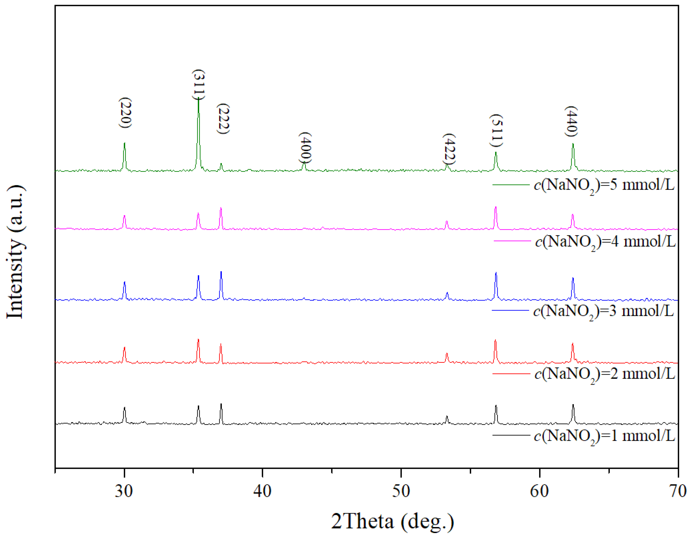
| NaNO2 (mmol/L) | a (Å) | D (nm) | Deposition Rate (nm/min) |
|---|---|---|---|
| 1 | 8.41 | 48 ± 9 | 32 |
| 2 | 8.41 | 54 ± 11 | 35 |
| 3 | 8.41 | 95 ± 9 | 43 |
| 4 | 8.41 | 57 ± 7 | 46 |
| 5 | 8.41 | 71 ± 21 | 42 |
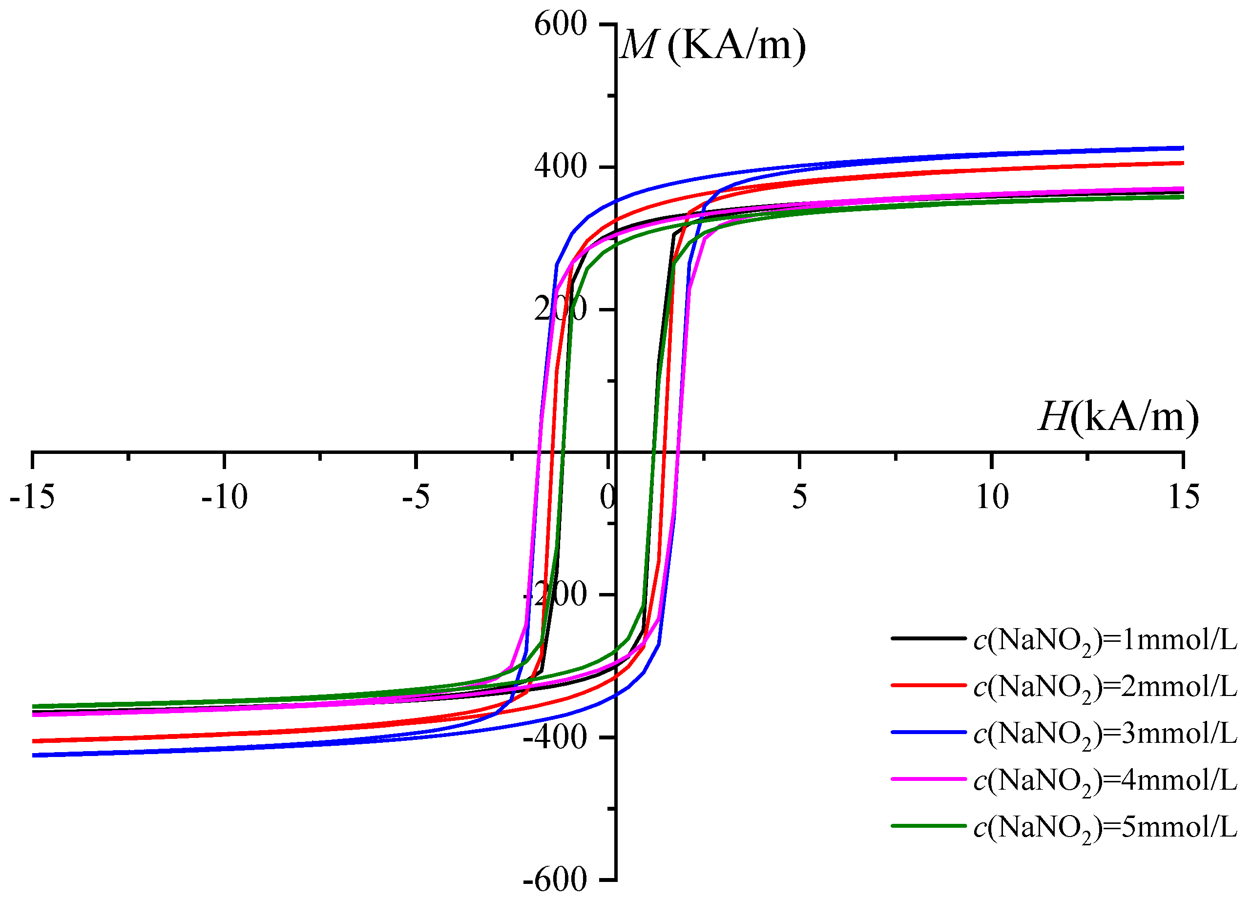
| c(NaNO2) (mmol/L) | 1 | 2 | 3 | 4 | 5 |
|---|---|---|---|---|---|
| Ms (kA/m) | 384 | 432 | 454 | 393 | 380 |
| Hc (kA/m) | 1.11 | 1.59 | 1.91 | 1.83 | 1.03 |
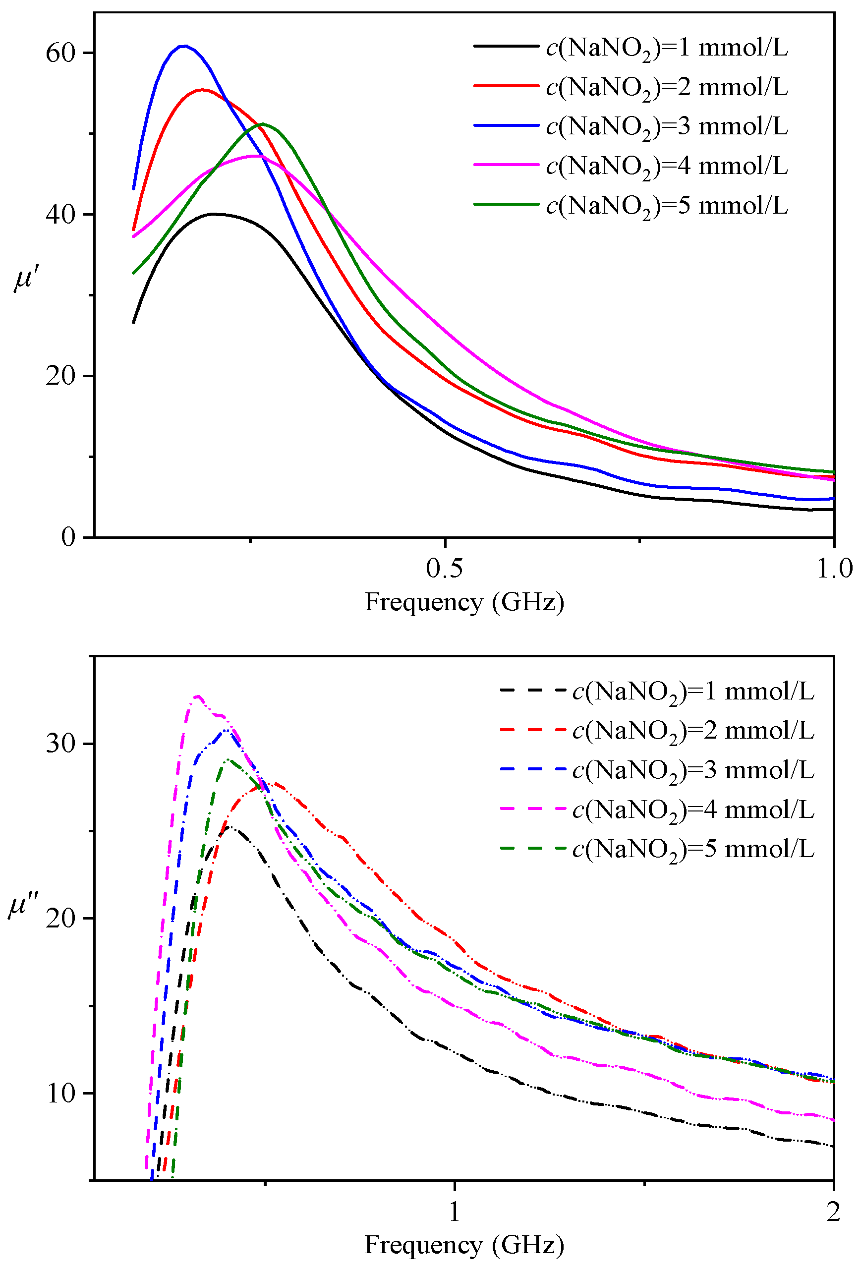
| c(NaNO2) (mmol/L) | μ′max | fr (MHz) |
|---|---|---|
| 1 | 40 | 401 |
| 2 | 55 | 482 |
| 3 | 61 | 375 |
| 4 | 48 | 265 |
| 5 | 53 | 367 |
Disclaimer/Publisher’s Note: The statements, opinions and data contained in all publications are solely those of the individual author(s) and contributor(s) and not of MDPI and/or the editor(s). MDPI and/or the editor(s) disclaim responsibility for any injury to people or property resulting from any ideas, methods, instructions or products referred to in the content. |
© 2024 by the authors. Licensee MDPI, Basel, Switzerland. This article is an open access article distributed under the terms and conditions of the Creative Commons Attribution (CC BY) license (https://creativecommons.org/licenses/by/4.0/).
Share and Cite
Liu, H.; Liao, J.; Huang, G.; Jiang, X.; Yu, Z.; Lan, Z.; Sun, K. Effect of Oxidant Concentration on Properties of Ferrite Films by Spin-Spray Deposition. Coatings 2024, 14, 120. https://doi.org/10.3390/coatings14010120
Liu H, Liao J, Huang G, Jiang X, Yu Z, Lan Z, Sun K. Effect of Oxidant Concentration on Properties of Ferrite Films by Spin-Spray Deposition. Coatings. 2024; 14(1):120. https://doi.org/10.3390/coatings14010120
Chicago/Turabian StyleLiu, Hai, Jihong Liao, Gang Huang, Xiaona Jiang, Zhong Yu, Zhongwen Lan, and Ke Sun. 2024. "Effect of Oxidant Concentration on Properties of Ferrite Films by Spin-Spray Deposition" Coatings 14, no. 1: 120. https://doi.org/10.3390/coatings14010120