Article

Effects of Gd2O3 Content on the Infrared Emissivity and Ablation Resistance of HfB2/SiC/TaSi2 Coating at 4400 kW/m2

1
School of Material Science and Engineering, Beijing Institute of Technology, Beijing 100089, China
2
School of Chemistry and Chemical Engineering, Yan’an University, Yan’an 716000, China
*
Author to whom correspondence should be addressed.
Coatings 2023, 13(8), 1397; https://doi.org/10.3390/coatings13081397
Submission received: 17 July 2023 / Revised: 2 August 2023 / Accepted: 4 August 2023 / Published: 9 August 2023

Abstract

:
To improve the infrared emissivity and the ablation resistance of HfB2/SiC/TaSi2 coatings for serving in heat flux of 4400 kW/m2, HfB2/SiC/TaSi2 coatings with different contents of high-emissivity Gd2O3 were prepared using atmospheric plasma spraying. The highest emissivity in 3–5 μm can reach up to 0.92 at 1273 K when the Gd2O3 content is at 10 vol.%. The increase in the emissivity is attributed to the additional electronic transitions induced by oxygen vacancies, which are generated by substituting Hf4+ with Gd3+. Due to the high emissivity, the surface temperature of the coating modified with 10 vol.% Gd2O3 was decreased by ~100 K. Meanwhile, the mass and the liner ablation rate are confirmed to be 4.28 × 10⁻⁷ kg/s and 2.15 × 10⁻⁷ m/s, respectively, which are decreased by 80% and 31% compared to the undoped HfB2/SiC/TaSi2 coating. During ablation, HfB2/SiC/TaSi2/Gd2O3 coating was oxidized to HfO2, Gd2Ta2O7, HfSiO4, and GdTaO4. A stable Hf–Ta–Gd–Si–O multiphase glass was formed on the surface of the coating, which could restrain oxygen penetration. However, the excessive amount of Gd2O3 is detrimental to the ablation performance due to its consumption of the SiO2 glass layer. These findings indicate that the addition of an appropriate amount of Gd2O3 could improve the anti-ablation performance of the modified coating.

1. Introduction

Carbon/carbon (C/C) composites have been used as structural and thermal components owing to their excellent mechanical properties and thermal resistance. However, the poor oxidation resistance of C/C limits its application in hypersonic vehicles [1,2]. The preparation of ultra-high-temperature ceramics (UHTCs) on the surface of C/C composites can block direct contact between C/C and oxygen at higher temperatures [3].
HfB2 is a representative UHTC with a low thermal expansion coefficient, high thermal conductivity, low catalytic coefficient, and high-temperature phase stability [4,5]. It has been reported that HfB2 has good oxidation resistance below 1473 K by forming liquid B2O3, which can hinder oxygen penetration and seal cracks and holes. However, when the temperature exceeds 1473 K, its protective ability is destroyed owing to the rapid volatilization of B2O3 [6]. It has been reported that adding 20–30 vol.% SiC to HfB2 can result in excellent antioxidant ablation performance below 1873 K [7]. Nevertheless, the formation of a SiC-depleted region remains a problem for the HfB2–SiC system. The additional introduction of TaSi2 improves the density and oxidation resistance of UHTCs as an additive phase because Ta2O5 reduces the volatilization rate of the glass SiO2 phase. Opila et al. [8] conducted a detailed analysis of the effect of TaSi2 addition to borides and showed that the addition of Ta can enhance the glass-phase viscosity and reduce HfO2 oxygen vacancies. However, it was also pointed out that the addition of TaSi2 did not enhance the antioxidant capacity of the coating at 2073 K and higher. Zhang et al. [9] have prepared HfB2–SiC–TaSi2 coating by a spark plasma sintering process and studied its oxidation behavior below 2073 K; the results showed that the generated Hf–Ta–B–Si–O composite glass layer could effectively reduce the coating-like diffusion rate and enhance the oxygen barrier ability of the coating.
However, TaSi2 did not improve oxidation protection capability above 2073 K because of Ta2O5 volatilization and melting of the metal oxides. This also renders the HfB2/SiC/TaSi2 system unable to meet the demands for high-temperature use. Therefore, it is urgent to seek a more stable additive phase for the HfB2-based composite system in ultra-high-temperature environments (≥2073 K).
In addition to improving the high-temperature properties of UHTCs, adding a radiation component to UHTCs is an effective way to indirectly improve high-temperature properties through cooling of the surface temperature during hypersonic flight via reradiation of the absorbed heat [10]. Preliminary work has indicated that rare-earth iron or rare-earth oxide doping can improve the surface infrared emissivity of coatings, which, in turn, enhances the radiation exchange capacity; this coupling can promote the antioxidant properties of the coatings [11,12,13,14,15,16,17,18]. Tan et al. [19] have studied the oxidation protection of a rare-earth-modified ZrB2–SiC coating using an oxyacetylene torch and found that rare-earth-modified coatings (Sm2O3 or Tm2O3 modified ZrB2–SiC) displayed high thermal stability and offered additional oxidation protection. Liu et al. [13] have prepared REO–HfO2 (REO = rare earth oxide = Tb4O7, Gd2O3, or Sm2O3) coatings and pure HfO2 coatings using atmospheric plasma spraying (APS) and studied the infrared radiation performance of these coatings. The results showed that the REO–HfO2 coatings displayed higher infrared emissivity than pure HfO2 coatings and exhibited excellent thermal resistance at 1873 K without undergoing a phase change and exfoliation. Tan et al. [14] have studied the hemispherical emissivity and ablation resistance of a Sm-doped ZrB2/SiC coating and found that 5 mol% Sm-doped ZrB2/SiC coating had the highest emissivity with dense oxide scale formation. Previous studies have shown that doped REOs could exhibit better oxygen-blocking capability and form a dense oxide scale upon oxidation [20,21,22,23,24]. Feng et al. [20] and Li et al. [21] have prepared La2O3-modified HfC–SiC coatings and ZrB2 coatings by supersonic atmospheric plasma spraying (SAPS), and the results showed that the incorporation of La2O3 could improve the ablation resistance. Wang et al. [22,23] have prepared Y2O3-modified MoSi2 coating by SAPS, and the results showed that adding Y2O3 at an appropriate concentration could increase the viscosity of SiO2 glass. Qian et al. [24] have studied the oxygen-blocking capability of La2O3-modified HfB2–SiC coating and found that 10 vol.% of La2O3 additive could improve the oxygen barrier properties.
Gd3+, as a lanthanide rare earth element in the middle position, has an oxide Gd2O3 with a melting point of ~2603 K, which is higher than that of Ta2O5 (2058 K). Meanwhile, Gd2O3 can react with the coating oxidation product HfO2 to form Gd2Hf2O7, thus influencing the structural stability of the oxide layer. Gd2Hf2O7 has a cubic pyrochlore structure (Fd3m) with a maximum pyrochlore–fluorite transition temperature of 2600–2800 K, and no Gd2Hf2O7 structural changes are observed below this temperature [17]. Due to the high melting point of Gd2O3 and high infrared emissivity and its ability to influence thermal stability, Gd2O3 can be added to HfB2/SiC/TaSi2 coatings to improve the high-temperature oxidation resistance properties (>2073 K) of the coatings. However, there are few studies on Gd2O3-modified coatings, and the effect of Gd2O3 at different contents on the ablation resistance of HfB2/SiC/TaSi2 has not been reported.
In this study, Gd2O3-modified HfB2/SiC/TaSi2 coatings were prepared by APS. The microstructure and component distribution of the coatings were examined to study the effect of varying contents of Gd2O3 on the characteristics of the coatings. In addition, the infrared radiative performance and ablation behavior of the coatings were systematically investigated to evaluate the effect of emissivity on the anti-ablation resistance properties of the Gd2O3-modified HfB2/SiC/TaSi2 coatings. Our findings will provide candidate materials for UHTCS, aiming at its potential ultra-high-temperature application in the aerospace field.

2. Experimental Procedure

2.1. Preparation

HfB2 particles (size range 1–3 μm, purity ≥ 99.9%, Beijing Zhongjinyan New Material Technology Co., Ltd., Beijing, China), SiC particles (size range 1–3 μm, purity > 99.9%, Beijing Zhongjinyan New Material Technology Co., Ltd.), TaSi2 particles (size range 1–3 μm, purity ≥ 99.9%, Beijing Zhongjinyan New Material Technology Co., Ltd.) and Gd2O3 particles (500 μm, purity ≥ 99.9%, Beijing HuaweiRuike Chemical Co., Ltd., Beijing, China) were used as raw materials for the preparation of HfB2, SiC, TaSi2, and Gd2O3 agglomerate powders, respectively. Five HfB2/SiC/TaSi2/Gd2O3 mixtures with different ratios were designed, as listed in Table 1. Among the five mixtures, the volume ratio of TaSi2 and SiC remained unchanged, and the volume ratio of Hf to Si in each group was fixed at 7:3, whereas the addition of Gd2O3 was varied at 0, 5, 10, 15, and 20 vol.%.
The raw particles were ball milled (JM-15L, Changsha Tianchuang Powder Co., Ltd., Changsha, China) with deionized water (Beijing Wanxin Chemical Industry Trade Center, Beijing, China) and PVA (0.4 wt%, Forsman Technology (Beijing) Co., Ltd., Beijing, China) for 5 h to produce a uniform slurry. The slurry was then immediately injected into a spray drying apparatus (Wuxi Dongsheng LGZ-8 spray drier, Wuxi, China) to agglomerate the powders. Before spraying, the agglomerated powders were treated using induction plasma spheroidization (IPS) to improve their density and sphericity. The IPS-treated particles with a particle size of 10–50 µm were sieved and used as feedstock powders for APS. The IPS treatment of the powders was carried out using a PL-35 model system (TEKNA Plasma System Inc., Sherbrooke, Canada). The other parameters of the IPS treatment of the HfB2/SiC/TaSi2/Gd2O3 agglomerate powders are listed in Table 2.
The coatings were prepared with US-made Praxair GTS-5500 equipment using APS, and the plasma torch used was SG 100. Powders were plasma sprayed onto C–C substrates (ø 0.025 m × 0.010 m) with an average coating thickness of roughly 200–250 µm. The parameters used for the deposition of the coatings are listed in Table 3.
For convenience, a naming convention based on the actual Gd2O3 concentration was used. For example, the Gd5 coating contains 5 vol.% Gd2O3 in the HfB2/SiC/TaSi2 coating.

2.2. Ablation Testing

The oxyacetylene flame (OAF) was selected to evaluate the anti-ablation property of the HfB2/SiC/TaSi2/Gd2O3 coatings. To achieve a long-term ablation of 180 s, the Mini-spray jet (Gastechnik GmbH & Co. KG, Neustadt/Wied, Germany) equipped with cooling air was used as the oxyacetylene spray gun in the OAF equipment. The local heat flux of the flame was measured using a Gordon gauge (AnYi Instrumentation Ltd., Shanghai, China), and the surface temperature of the specimens was obtained using an MR1S dual colorimetric infrared thermometer (Raytek Marathon, Santa Cruz, CA, USA).
During ablation, the distance between the gun and the specimen was 0.045 m. The pressure and flow rate of oxygen and acetylene were 0.5 MPa, 2.5 × 10⁻⁴ m3/s, and 0.05 MPa, 1.7 × 10⁻⁴ m3/s, respectively. In this case, the peak heat flux of the flame was 4400 kW/m2. The ablation property of the coatings was characterized using the mass and linear ablation rates, which were calculated by the following formulae:
R m = Δ m Δ t
R l = Δ l Δ t
where Δ m and Δ l are the change in the mass and thickness of the sample, respectively, and Δ t is the ablation time. The ablation rates of the samples were based on the average values calculated for five formulation samples.

2.3. Characterization

The composition of HfB2/SiC/TaSi2/Gd2O3 coatings before and after oxidation testing was analyzed by X-ray diffraction (XRD, X’ Pert PRO), with Cu Kα radiation, a step-size of 0.04°/s, and a 1 s counting rate. The morphology of the coatings was analyzed by scanning electron microscopy (SEM, JSM-6460), and energy dispersive spectroscopy (EDS) was used for elemental analysis. The porosity of the sprayed coatings before ablation was estimated by image analysis using Image J software and the average from 10 pictures was taken for each sample. An infrared spectrometer (IR-2, Shanghai Chengbo Optoelectronic Technology Co., Ltd., Shanghai, China) was employed to measure the infrared emissivity of the coatings at room temperature, whereas the infrared emissivity at 1273 K was tested using a Nicolet 6700 infrared radiation instrument at the China National Supervision and Test Center for Infrared and Industry Galvanothermy Product Quality (Wuhan, China).

3. Results and Discussion

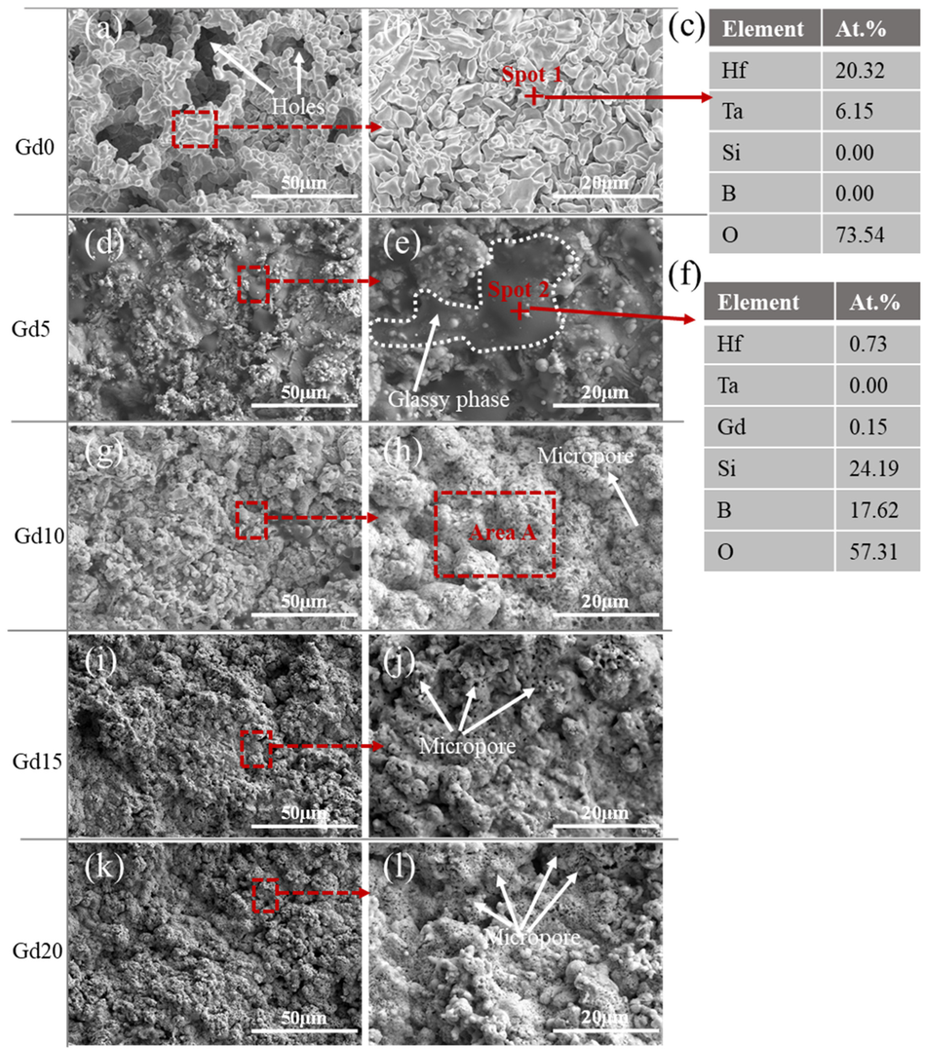
3.1. Phase Composition and Morphology of as-Sprayed Coatings

Figure 1 shows the XRD patterns and probable phases of the as-prepared coatings before ablation. As shown in Figure 1, the phase composition of the as-prepared coatings was mainly HfB2 (PDF#75-1049, hexagonal, and spatial group structure is P6/mmm (191)), and diffraction of SiC and TaSi2 was not observed. The reasons for the disappearance of the SiC and TaSi2 diffraction peaks may be as follows: (i) HfB2 and SiC form a eutectic phase, HfSi2 (PDF#72-1201, orthorhombic, and spatial group structure is Cmcm (63)), during the process [25]. (ii) The amount of TaSi2 is relatively small. (iii) There is a low penetration depth of X-rays in SiC. In addition, the Gd2O3 (PDF#86-2477, cubic, and spatial group structure is la-3(206)) phase was found in the Gd5, Gd10, Gd15, and Gd20 coatings, and the intensity of the Gd2O3 diffraction peak gradually increased with increasing Gd2O3 content. It can be seen in Figure 1 that the Gd2O3 not only reacted with other phases, but also did not melt with the other phases. The HfO2 (PDF#21-0904, orthorhombic, and spatial group structure is Pbcm (57)) diffraction peak was observed in all five coatings, indicating that the powder at the edge of the jet during the spraying process was oxidized by O2 in air owing to the absence of a protective atmosphere. In addition, the agglomerated powders in the center of the jet inevitably react with oxygen when sprayed onto the C–C substrate. HfO2 was also produced while the powder on the substrate cooled down.
Figure 2 shows the surface morphology of the as-sprayed coatings. All five coatings show good powder-spreading characteristics with few surface undulations and flat fusion condensation spreading layers. This planar laminar feature can increase the contact area with the deposited powder, reduce the interlayer defects caused by differences in shape orientation, and facilitate a dense coating. In particular, the spreading performance of the coating improved with increasing Gd2O3 content. This indicates that the introduction of Gd2O3 with a lower melting point can improve the deposition effect of the powder and increase the density of the coating.
Figure 3a–e show the cross-sectional morphology of the as-sprayed coatings. It can be seen that the thickness of all the coatings was 200–300 μm, and these coatings were perfectly integrated with the C–C substrate. It can be seen that the Gd0 coating has a large coarse area. With an increase in Gd2O3 addition, the loose area decreases and the cross-sectional spalling crater characteristics gradually weaken. Table 4 lists the porosity of the five coatings. It can be seen that the coating porosity decreases from 19.91% to 11.28%, indicating that the introduction of Gd2O3 improves the powder deposition efficiency and helps to enhance the coating density. With increased density, resistance to oxidation improves. Figure 3f shows the elemental distribution of the Gd10 coating, and it can be seen that the Hf, Ta, Si, and Gd in the coating are uniformly distributed, indicating that there was no elemental bias inside the coating.

3.2. Infrared Radiation Property of as-Prepared Coatings

Figure 4 shows the infrared emissivity of the Gd2O3-modified coatings at room and high temperature in the 3–5 µm band. At room temperature, the emissivity increased from ε = 0.69 for the Gd0 coating to ε = 0.72, 0.73, 0.74, and 0.71 for the Gd5, Gd10, Gd15, and Gd20 coatings, respectively. At temperature T = 1273 K, the emissivity increased from ε = 0.85 for Gd0 coating to ε = 0.88, 0.92, 0.91, and 0.89 for the Gd5, Gd10, Gd15, and Gd20 coatings, respectively. The emissivity improved with an increase in Gd2O3 content, and the highest emissivity was reached for the Gd15 coating at room temperature and the Gd10 coating at high temperatures. Moreover, the high-temperature emissivity was much higher than that at room temperature for all five coatings. This is attributed to the increased lattice vibration and electron–phonon coupling at high temperatures, which improves infrared lattice absorption and multi-phonon absorption.
The above variation in emissivity can be attributed to two reasons: Gd2O3 has a high emissivity [26] and Gd3+ ions with larger radii and lower atomic weights enter the HfO2 lattice, occupying the Hf4+ ion positions. Some oxygen ions in the lattices spill over to form oxygen vacancies, which then attract and trap electrons to form color centers [27]:
G d 2 O 3 H f O 2 2 G d H f + 3 O O + V O . . O O V O . . + 2 e + 1 2 O 2
where G d H f is a Gd3+ ion occupying the position of Hf, O O represents O2− ion in its normal position, V O . . is an oxygen vacancy, and e is an electron.
The oxygen vacancies and color centers are the same as those in this discussion. Oxygen vacancies can cause localization of the electronic state in the material bandgap, promoting additional electronic transitions. According to [28], neutral oxygen vacancies significantly increase the emissivity of ZrO2, owing to a mid-gap state caused by oxygen vacancies in ZrO2. In this study, the oxygen vacancies produced by the substitution of Hf4+ with Gd3+ have energy levels inside the HfO2 band gap. Thus, both the Gd3+ emission band and the oxygen vacancies produce localized energy levels inside the HfO2 band gap, such that exciting electrons into these localized energy levels promotes increased infrared emissivity. In addition, Gd2O3 could react with oxidation products (e.g., HfO2) to form a new phase, Gd2Hf2O7. Because the cation radii ratio (rGd3+/rHf4+) is lower than 1.46 and there is an excess amount of anions (O2−), Gd2Hf2O7 has a defective fluorite-type structure [13,29], which is expected to improve material emissivity.
When compared with the Gd0 coating, the maximum difference of the high-temperature emissivity of Gd2O3-modified coating in the 3–5 µm band is 0.07, which is an improvement of 8.2%, indicating that the introduction of Gd2O3 has better infrared radiation performance, and Gd2O3 mainly acts in the high-temperature oxidation phase of the coating.
Therefore, the improvement in infrared emissivity with increasing Gd2O3 content from 0 to 10 vol.% can be attributed to the production of Gd-doped HfO2 and Gd2Hf2O7 phase because they both have high emissivity. When doped with 10 vol.% Gd2O3, the Gd-doped HfO2 reaches a saturated doping state. The decrease in infrared emissivity with an increase in Gd2O3 content from 10 to 20 vol.% is due to the reduction of Gd-saturated HfO2, which has a higher emissivity than Gd2Hf2O7.

3.3. Ablation Resistance of Coatings

3.3.1. Macro-Oxidation Behavior of the Coatings

Figure 5 shows the local heat flux distribution and surface temperature curves of the coatings during 180 s of ablation. As shown in Figure 5a, the peak heat flux was 4400 kW/m2 within a radial distance of 0.002 m, and the heat flux values decreased radially outwards. Illustrations (i) and (ii) in Figure 5b show flame photographs during the free jet and ablation tests, respectively. Because the ablation gun in this study had a cooling device, the free jet flame length was 91 mm, which is shorter than the flame length without a cooling device [30].
Figure 5b presents the surface temperature curves of the five coatings during heating. The surface temperature increased rapidly for the Gd0 and Gd20 coatings and, subsequently, it reached a steady state value equal to ~2173 K for the Gd0 coating and ~2073 K for the Gd20 coating. For the Gd5, Gd10, and Gd15 coatings, the surface temperature increased continuously during the ablation process, indicating that their oxidation products change continuously in this ablation environment. During ablation, identical heating and thermal convections occur in the ablation center; thus, the surface temperature is dominated by heat radiation and conduction of the coating materials. Compared with Gd0 coating, the Gd2O3-modified coatings exhibited a surface temperature ~100 K lower; this is consistent with Gd2O3-doped coatings having a lower emissivity than Gd0 coating.
Macrographs of all the coatings before and after ablation are shown in Figure 6. The ablation centers of the coatings that suffered the most heat flux were chosen to evaluate their ablation resistance and detailed microstructure. Before ablation, the surfaces of all the coatings appeared dark grey; therefore, Figure 6a was used to represent all the coatings. In Figure 6b–f, the ablation edges of the five coatings changed to white. The ablation centers of Gd0, Gd5, and Gd10 were white, whereas those of the other two coatings were yellow, which is related to the Gd2O3 content. Additionally, edge warping appeared in the Gd0 and Gd5 coatings, and spalling areas and bubbles appeared in the Gd20 coating. It can be speculated that the Gd10 and Gd15 coatings exhibit better ablation resistance.
Figure 7 shows the mass and linear ablation rates under the same ablation conditions. The Gd0 coating exhibits the highest mass and linear ablation rates of 2.14 × 10⁻⁶ kg/s and 3.13 × 10⁻⁷ m/s, respectively. With an increase in the Gd2O3 content, the mass and linear ablation rate of the composites decreased. When the addition of Gd2O3 was 10 vol.%, the mass and linear ablation rates were 4.28 × 10⁻⁷ kg/s and 2.15 × 10⁻⁷ m/s, 80% and 31% lower than those of the Gd0 coating, respectively. These results suggest that the oxidative ablation resistance of the surface-modified composites was effectively improved by adding Gd2O3. There are three possible reasons for this. First, the modified coatings have a denser microstructure, as seen in Figure 2 and Figure 3. Second, the emissivity of the modified coatings is much higher than that of the coatings without modification, as shown in Figure 4. Third, the ablative oxidation products of the modified coatings are more stable, producing a better oxygen barrier.

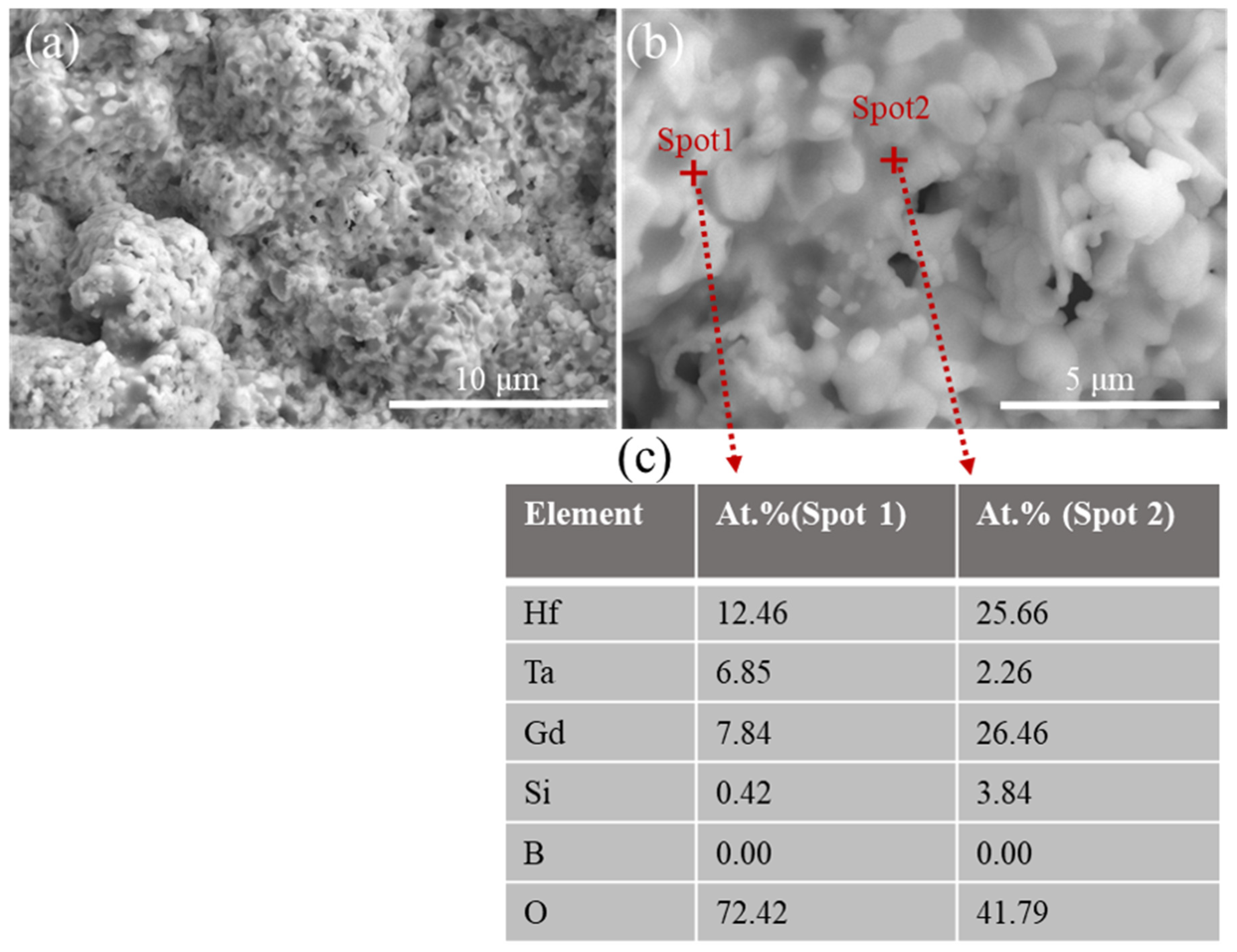
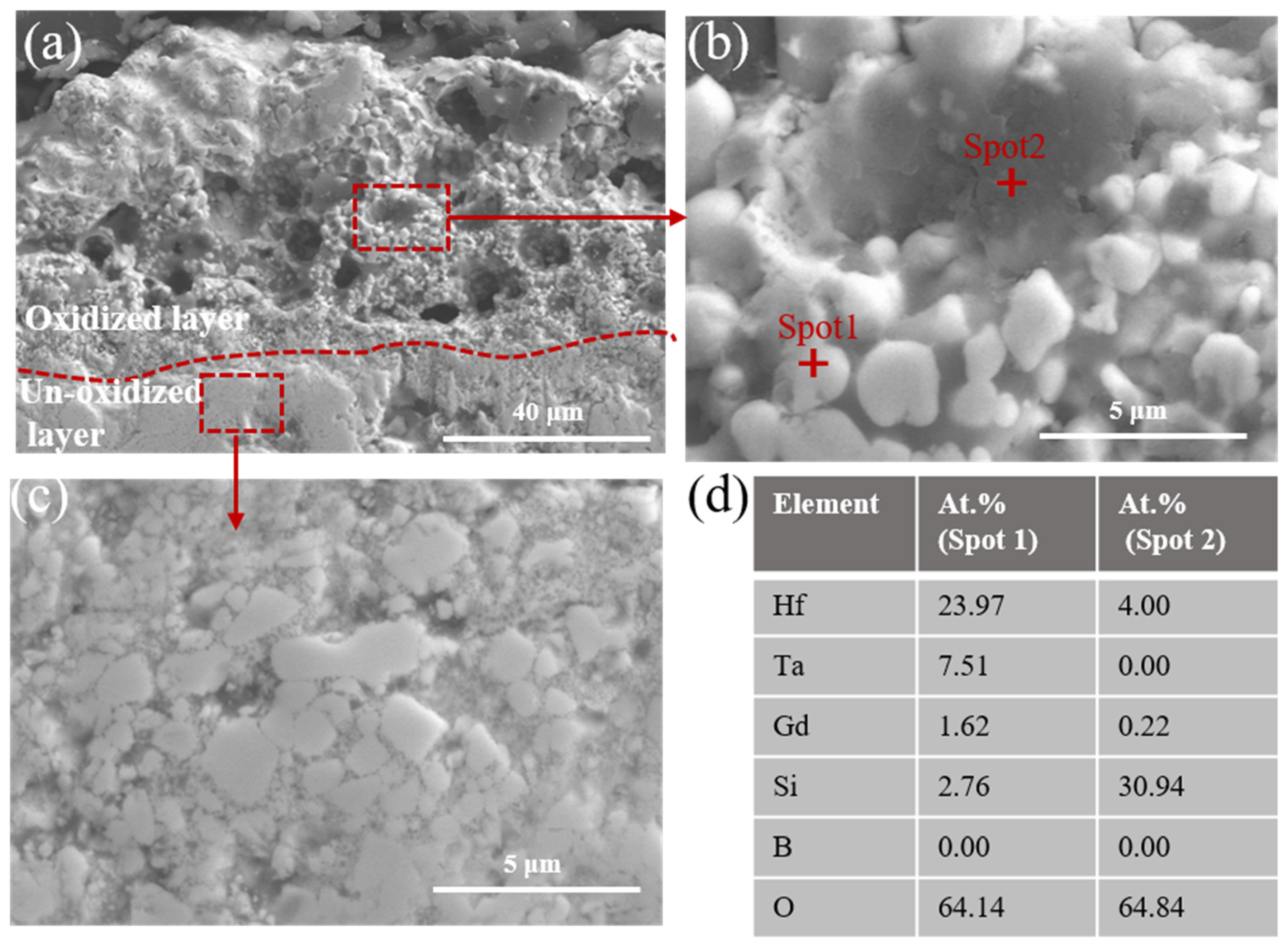
3.3.2. Microstructure Analysis of the Ablation Layer

Figure 8 shows the surface morphology and related EDS results of the ablated Gd0 and Gd5 coatings. After ablation for 180 s, a porous structure formed on the surface of the ablated Gd0 coating (Figure 8a,b), and these open pores have a size larger than 10 μm. In addition, the main phase is composed of Hf–Ta–O in the Gd0 coating in Figure 8c and no SiO2 phase is detected. At a surface temperature of ~2173 K in the Gd0 coating, the SiO2 glass phase volatilizes violently, which causes serious structural damage to the surface, resulting in a large number of open pores. Therefore, the oxide penetrates the internal coating and causes a high mass ablation rate of the Gd0 coating (see Figure 7).
With the incorporation of Gd2O3, the compactness of the oxide layer increases significantly, as indicated by the surface morphology in Figure 8d–l. For the Gd5 coating, it can be seen that there is a grayish-black liquid droplet that covers the surface of the cluster particle tissue and occluded pores, and other defects can be seen on the surface, as shown in Figure 8d,e. In Figure 8f, it can be inferred that the grayish-black liquid droplet is a borosilicate glass phase, which is mainly composed of SiO2 and B2O3, and the presence of this self-healing glass phase maintains the sealing property of the oxide layer.
For the Gd10, Gd15, and Gd20 coatings, it was found that the characteristics of glass-phase coverage are gradually weakened compared with those of Gd5, and the surfaces are mainly characterized by particle clusters (see Figure 8g,l). There are large micropores (<1 μm) observed on these particle clusters under high magnification for the ablated Gd10, Gd15, and Gd20 coatings (see Figure 8h,j and Figure 8l, respectively). The size of the micropores decreased with increasing Gd2O3 content. The pores suggest the possible formation of a liquid phase during oxidation. The liquid phase eventually becomes volatilized as the local temperature exceeds the evaporation temperature. This liquid phase is likely B2O3, SiO2, or a combination of both. Owing to the strong sealing of the coating resulting in a shallow depth of oxygen erosion, there is no internal oxide layer of sufficient depth to provide SiO2 transport for the surface layer. When the oxidation temperature is higher than 2073 K or the oxygen partial pressure is low, SiC undergoes active oxidation to generate gaseous SiO, intensifying the generation of surface-layer pores.
Because of the similar surface morphology of the Gd10, Gd15, and Gd20 coatings, the Gd10 coating was used for detailed morphology analysis. Figure 9 shows a high-magnification image and the related EDS results for the ablated Gd10 coating shown in Figure 8g,h. Lighter and darker regions can be observed. In Figure 9b,c, it can be seen that spot1 (lighter region) is mainly composed of Hf, Ta, and Gd oxides, whereas spot2 (darker region) is mainly composed of Hf and Gd oxides and a small amount of Si. Combined with the fact that the surface of Gd10 still shows excellent oxidation resistance, it can be inferred that in addition to the sealing effect of the glass phase, the introduced Gd2O3 is also a key factor determining the oxidation resistance of the coating under the test conditions.
The cross-sectional morphology of the ablated coatings is shown in Figure 10. Compared with the cross-sectional morphology before ablation in Figure 3, the cross-sectional morphology of the five coatings changed significantly after the ablation test, and the Gd2O3-modified coatings show similar layered structure. Figure 11 shows the EDS point-to-point line scan obtained across the Gd10 coating, starting from the ablated surface (x = 0 μm) to the interior coating (x = 150 μm). The O content of the outer layer is significantly higher than that of the inner layer, indicating that the outer layer is an oxide layer where oxidation reactions occur, whereas the inner layer is non-oxidized. Therefore, the ablated coating can be separated into a loose porous oxidized layer and a dense non-oxidized layer, and there is a clear film between the two layers.
The Gd0 coating was completely oxidized and there were many loose areas and large holes in the cross-section. This may be due to internal B2O3 and SiO escaping to the surface layer as well as the depletion of SiC. During the escape, the volatile gas damages the particle structure, loosening the porous oxide layer. Because the surface temperature (~2173 K) of the Gd0 coating is above the glass-phase volatilization temperature (Figure 5), the glass-phase self-healing function cannot be performed, and, because of the large porosity of the Gd0 coating, oxygen quickly penetrates the inner coating during the ablation process, and the coating loses its oxygen barrier function.
With Gd2O3-modified coating, a layered structure can be observed. In the Gd5 coating, large pores similar to those in the Gd0 coating are also observed, and the formation of these pores is likely related to the depletion of SiC. However, the oxide layer of the Gd5 coating is significantly thinner than that of the Gd0 coating. This can be attributed to the fact that the addition of Gd2O3 increases the density of the Gd5 coating (Table 4), which, in turn, hinders the diffusion of oxygen into the interior of the coating.
In the Gd10 coating, the oxidized layer appears relatively dense, and the thickness of the oxidized layer is lower than that of the Gd5 coating. The microstructure of the Gd15 coating is similar to that of the Gd10 coating, which has a denser structure. In the Gd20 coating, the oxidized layer contains many pores and the thickness of the oxidized layer increases compared to that of the Gd10 coating, further revealing that excessive Gd2O3 content aggravates the oxidation of the coating.
The thicknesses of the oxidized and non-oxidized layers of all the ablated coatings were measured and are summarized in Table 5. It can be seen that the Gd10 and Gd15 coatings exhibit the best oxidation resistance among all the coatings, having impact macrostructure and the largest thickness of non-oxidized coatings after 180 s ablation. However, the Gd0 coating was completely oxidized during the ablation test. Therefore, doping with Gd2O3 was beneficial for oxidation resistance.
To further compare the differences between the oxidized and non-oxidized layers of the coatings, the Gd10 coating with the best oxidation resistance was selected for observation at higher magnification, as shown in Figure 12. The oxide layer on the upper side of the red dashed line in Figure 12a is loose and contains holes, whereas the non-oxide layer below the red line retains the sprayed state characteristics and is dense. Figure 12b shows a magnified cross-section of the oxide layer, which is composed of minor oxide particles and dark, glassy phases embedded in the interstices. The EDS analysis in Figure 12b shows that region 1 contains Hf, Ta, Gd, Si, and O, indicating that the particle organization is mainly a compound of Hf–Ta–Gd–Si–O, mainly Hf, Si, and O with a small amount of Gd, indicating that the glass phase is SiO2 and HfSiO4, consistent with the results obtained by ablating the surface. Figure 12c shows a magnified image of the non-oxidized layer wherein the interstitial-phase distribution of bright and dark bands in the non-oxidized layer, with no loose particles, indicates a good ablation protection effect of Gd10 coating under the oxyacetylene combustion flow test of 4400 kW/m2.
Figure 13 shows the XRD patterns and probable phases of the ablated coatings. The phase compositions of the Gd0 coatings are primarily cubic c-HfO2 (PDF#53-0560) and Hf6Ta2O17 (PDF#44-0998, orthorhombic). HfO2 undergoes a transition from monoclinic to cubic at 1650 °C accompanied by volume shrinkage and a transition from cubic to monoclinic, causing volume expansion during cooling. HfSiO4 (PDF#77-1759, tetragonal, and spatial group structure is 141/amd (141)), GdTaO4 (PDF#24-0441, monoclinal, and spatial group structure is 12/A), and m-HfO2 (PDF#78-0049, monoclinic, and spatial group structure is P21/c(14)) were detected in the Gd5, Gd10, and Gd15 coatings. With an increased content of Gd2O3, Gd2Hf2O7 (PDF#24-0425, cubic, and spatial group structure is Fm3m (225)) was detected in the Gd10, Gd15, and Gd20 coatings. Gd2Hf2O7 has excellent high-temperature thermal stability of the oxide layer, which can reduce stress within the coating and hinder crack sprouting [31]. Considered together with the edge warping of the ablated Gd0 and Gd5 coatings, it can be assumed that the introduced Gd2O3 plays a role in stabilizing the HfO2 phase, suppressing volume change in the coating owing to phase change and improving the thermal suitability of the coating and substrate.

3.4. Ablation Mechanism

During the ablation process, HfB2, SiC, TaSi2, and Gd2O3 may react as follows [32,33,34,35]:
H f B 2 s + 5 / 2 O 2 g = H f O 2 s + B 2 O 3 l
TaSi 2 s + 13 / 4 O 2 g = 1 / 2 Ta 2 O 5 s + 2 Si O 2 l
B 2 O 3 l = B 2 O 3 g
Ta2O5(s) = Ta2O5(l)
S i C s + 2 O 2 g = S i O 2 l + C O 2 g
2 S i C s + 3 O 2 g = 2 S i O 2 l + 2 C O g
S i C s + O 2 g = S i O g + C O g
S i O 2 l = S i O 2 g
Hf O 2 ( s ) + Si O 2 ( l ) = HfSi O 4 ( s )
G d 2 O 3 ( s ) + 2 Hf O 2 ( s ) = G d 2 H f 2 O 7 ( s )
G d 2 O 3 s + Ta 2 O 5 s = 2 GdTa O 4 s
Ta 2 O 5 s + 6 Hf O 2 s = Hf 6 Ta 2 O 17 s
To analyze the oxidation mechanism of the coatings, the Gibbs free energies (ΔG) for reactions R3-R4, R7-R9, and R11 were calculated, as shown in Figure 14. The related thermodynamic data were obtained from FactSage 8.2 software. From Figure 14, in the temperature range of 500~2200 K, the ΔG of all reactions is negative, indicating all the reactions can occur spontaneously. From the thermodynamic calculation results, it indicates that TaSi2 of the outer layer is preferentially oxidized to form a porous Ta2O5 layer owing to its lower Gibbs free energy, and the oxidation trend of HfB2 is slightly weaker than TaSi2. Owing to the lower ΔG of reaction 7 than those of reaction 3-4, the generated silica glass with a good self-healing ability can fill defects of the loose structure and porous Ta2O5 and HfO2 forming a relatively dense outer layer.
In the Gd0 coating, the HfB2/SiC/TaSi2 coating is oxidized to HfO2, Ta2O5, and SiO2 according to reactions (3), (4), and (7). HfO2 reacts with Ta2O5 to generate a new stable phase (Hf6Ta2O17) (reaction (14)). When the ablation temperature (2173 K) is higher than the melting points of Ta2O5 (~2058 K) and SiO2 (1873–1973 K), a portion of SiO2 and Ta2O5 melt and evaporate. Evaporation of the gaseous products (CO, CO2, B2O3, SiO2, and Ta2O5) leaves small pores in the coating. The Ta–Si–O glass layer can seal some of these voids. Because Hf6Ta2O17 has low thermal conductivity (2.89 W/m K) and a high melting point (~2723 K), Hf6Ta2O17 particles play a pinning role in the Ta–Si–O glassy layer, inhibiting the formation and propagation of cracks [36]. Unfortunately, the porous structure of the original Gd0 coating (see Table 2) offers channels for oxygen diffusion, thereby degrading the ablation performance (see Figure 5 and Figure 8).
For the HfB2/SiC/TaSi2/Gd2O3 coating, the introduction of Gd2O3 results in a lower surface temperature under the same test conditions due to the increased emissivity, which directly reduces the oxidation rate of the coating and the volatilization rate of the glass phase. Moreover, the melting point of Gd2O3 (~2573 K) is significantly higher than those of Ta2O5 (~2058 K) and SiO2 (1873–1973 K), avoiding the negative impact of lowering the oxide eutectic temperature on the thermal stability of the oxide layer. When the surface temperature is 2073 K, Gd2O3 replaces Ta2O5 and SiO2 to play a role in stabilizing the HfO2 phase transition owing to its high melting point, thus promoting a dense oxide layer. Gd2O3 reacts with Ta2O5 to generate GdTaO4 (reaction 12), and HfO2 reacts with SiO2 to generate a new stable phase (HfSiO4) (reaction 11). In the Gd5 coating, HfSiO4, GdTaO4, and HfO2 are the main phases on the ablated surface and have a pinning effect on the glass layer because of their high melting points. Therefore, the Gd5 coating has a thinner oxidation layer than the Gd0 coating (Figure 10b); however, the oxidation layer exhibits a porous structure owing to the presence of a small amount of Gd2O3.
With an increasing amount of Gd2O3, a new phase of Gd2Hf2O7 (melting point ~2573 K) is generated. The Gd2Hf2O7 phase can suppress the volume expansion accompanying the HfO2 cubic/monoclinic phase transition during the cooling process and reduce stress concentration in the coating. However, the decomposition temperature of Gd2Hf2O7, with a cubic pyrochlore structure, is ~2373 K [17], so it can maintain phase stability when T ≥ 2073 K. In the Gd10 and Gd15 coatings, HfSiO4, GdTaO4, HfO2, and Gd2Hf2O7 are the main phases. The dissolution of higher-melting-point oxides forms a stable Hf–Ta–Gd–Si–O multiphase glass on the surface of the coating (see Figure 9c). High-melting-point particles, such as HfO2, GdTaO4, HfSiO4, and Gd2Hf2O7, are dispersed in the Hf–Ta–Gd–Si–O glassy layer as “hard particles” when the glass layer is softened during oxidation at high temperatures. As a result, the Gd10 and Gd15 coatings exhibit better resistance to oxidation than the Gd5 coating (See Figure 10c,d).
However, excessive Gd2O3 can cause excessive consumption of SiO2 in the Gd20 coating, resulting in the formation of more Gd2Hf2O7, making the generated glass very viscous and imparting its self-healing ability. Therefore, doping with a high content of Gd2O3 (>15 vol.%) negatively affects the oxidation-blocking capability of the HfB2/SiC/TaSi2 coating.

4. Conclusions

Gd2O3-modified HfB2/SiC/TaSi2 coatings were successfully prepared by APS. Through the oxyacetylene flame test, the ablation resistance of the modified coatings was evaluated at 4400 kW/m2 for 180 s. The effects of varying Gd2O3 contents on the microstructure, infrared radiative property, and ablation resistance of the HfB2/SiC/TaSi2 were investigated. With the growth of Gd2O3 content increased from 0 vol.% to 20 vol.%, the coating porosity decreased from 19.91% to 11.28%, indicating that the addition of Gd2O3 improved the coating density. Moreover, because of the additional electronic transitions promoted by oxygen vacancies in HfO2, the addition of Gd2O3 improved the infrared emissivity of the HfB2/SiC/TaSi2 coatings. The Gd10 coating possessed the highest emissivity in the 3–5 μm band at 1273 K, up to 0.92. Due to the highest emissivity, the Gd10 coating possessed the lowest surface temperature of 2073 K. Thus, the Gd10 coating had mass and linear ablation rates of 4.28 × 10⁻⁷ kg/s and 2.15 × 10⁻⁷ m/s, 80% and 31% lower than those of the Gd0 coating, respectively. Further, the Gd10 coating showed excellent oxygen barrier performance due to the stable Hf–Ta–Gd–Si–O glass formed on the surface of the Gd10 coating, which inhibited oxide penetration into the internal coating. Nevertheless, an excessive amount of Gd2O3 is detrimental to the ablation performance owing to its excessive consumption of SiO2. This study demonstrates that the addition of an appropriate amount of Gd2O3 is an effective way to improve the ablation resistance of HfB2/SiC/TaSi2 coatings at a heat flux of 4400 kW/m2.

Author Contributions

Experiment and Manuscript writing, J.L. and M.X.; Supervision and experimental guidance, S.Z. and Y.L. All authors have read and agreed to the published version of the manuscript.

Funding

This research received no external funding.

Data Availability Statement

All research data supporting this publication are directly available within this publication.

Conflicts of Interest

The authors declare that they have no known competing financial interest or personal relationship that could have appeared to influence the work reported in this paper.

References

  1. Sziroczak, D.; Smith, H. A review of design issues specific to hypersonic flight vehicles. Prog. Aerosp. Sci. 2016, 84, 1–28. [Google Scholar] [CrossRef] [Green Version]
  2. Windhorst, T.; Blount, G. Carbon-carbon composites: A summary of recent developments and applications. Mater. Eng. 1997, 18, 11–15. [Google Scholar]
  3. Dhami, T.L.; Ball, O.P.; Awasthy, B.R. Oxidation-resistance carbon-carbon composites up to 1700 °C. Carbon 1995, 33, 479–490. [Google Scholar] [CrossRef]
  4. Fahrenholtz, W.G.; Hilmas, G.E.; Talmy, I.G.; Zaykoski, J.A. Refractory Diborides of Zirconium and Hafnium. J. Am. Ceram. Soc. 2007, 90, 1347–1364. [Google Scholar] [CrossRef]
  5. Navrotsky, A. Thermochemical insights into refractory ceramic materials based on oxides with large tetravalent cations. J. Mater. Chem. 2005, 15, 1883–1890. [Google Scholar]
  6. Parthasarathy, T.A.; Rapp, R.A.; Opeka, M.; Kerans, R.J. A model for the oxidation of ZrB2, HfB2 and TiB2. Acta Mater. 2007, 55, 5999–6010. [Google Scholar]
  7. Guérineau, V.; Julian-Jankowiak, A. Oxidation mechanisms under water vapour conditions of ZrB2-SiC and HfB2-SiC based materials up to 2400 °C. J. Eur. Ceram. Soc. 2018, 38, 421–432. [Google Scholar] [CrossRef]
  8. Opila, E.; Levine, S.; Lorincz, J. Oxidation of ZrB2-and HfB2-based ultra-high temperature ceramics: Effect of Ta additions. J. Mater. Sci. 2004, 39, 5969–5977. [Google Scholar]
  9. Zhang, M.; Ren, X.; Chu, H.; Lv, J.; Li, W.; Wang, W.; Yang, Q.; Feng, P. Oxidation inhibition behaviors of the HfB2-SiC-TaSi2 coating for carbon structural materials at 1700 °C. Corros. Sci. 2020, 177, 108982. [Google Scholar] [CrossRef]
  10. Van Wie, D.M.; Drewry, D.G.; King, D.E.; Hudson, C.M. The hypersonic environment: Required operating conditions and design challenges. J. Mater. Sci. 2004, 39, 5915–5924. [Google Scholar]
  11. Yang, Z.X.; Ni, L.Y.; Yang, J.; Ma, K.Z. Microstructure and radiation property of Tb4O7 doped Cr2O3-TiO2-based high emissivity coating. Surf. Coat. Technol. 2018, 5, 154–158. [Google Scholar]
  12. Xu, J.; Liu, Y.; Ma, Z.; Zhu, S.; Wang, Y.; Chen, H.; Ma, K. Infrared radiative performance and anti-ablation behaviour of Sm2O3 modified ZrB2/SiC coatings. Ceram. Int. 2021, 47, 400–408. [Google Scholar] [CrossRef]
  13. Liu, F.; Cheng, X.; Mao, J.; Li, Q.; Zeng, X. Effects of rare-earth oxide doping on the thermal radiation performance of HfO2 coating. Ceram. Int. 2019, 45, 13004–13010. [Google Scholar] [CrossRef]
  14. Tan, W.; Adducci, M.; Petorak, C.; Thompson, B.; Brenner, A.E.; Trice, R.W. Effect of rare-earth dopant (Sm) concentration on total hemispherical emissivity and ablation resistance of ZrB2/SiC coatings. J. Eur. Ceram. Soc. 2016, 36, 3833–3841. [Google Scholar] [CrossRef]
  15. Brenner, A.E.; Peña, A.A.; Phuah, X.L.; Petorak, C.; Thompson, B.; Trice, R.W. Cyclic ablation of high-emissivity Sm-doped ZrB2/SiC coatings on alumina substrates. J. Eur. Ceram. Soc. 2018, 38, 1136–1142. [Google Scholar] [CrossRef]
  16. Sato, S.; Takahashi, R.; Kobune, M.; Gotoh, H. Basic properties of rare earth oxides. Appl. Catal. A Gen. 2009, 356, 57–63. [Google Scholar] [CrossRef]
  17. Guskov, V.N.; Tyurin, A.V.; Guskov, A.V.; Gagarin, P.G.; Khoroshilov, A.V.; Gavrichev, K.S. Thermal expansion and thermodynamic properties of gadolinium hafnate ceramics. Ceram. Int. 2020, 46, 12822–12827. [Google Scholar] [CrossRef]
  18. Zhang, Y.; Wen, D. Infrared emission properties of RE (RE = La, Ce, Pr, Nd, Sm, Eu, Gd, Tb, and Dy) and Mn co-doped Co0.6Zn0.4Fe2O4 ferrites. Mater. Chem. Phys. 2012, 131, 575–580. [Google Scholar] [CrossRef]
  19. Tan, W.; Adducci, M.; Trice, R.; Fahrenholtz, W. Evaluation of Rare-Earth Modified ZrB2-SiC Ablation Resistance Using an Oxyacetylene Torch. J. Am. Ceram. Soc. 2014, 97, 2639–2645. [Google Scholar] [CrossRef]
  20. Feng, G.; Li, H.; Yao, X.; Liu, T.; Jia, Y.; Yang, L.; Li, B. Mechanical properties and ablation resistance of La2O3-modified HfC-SiC coating for SiC-coated C/C composites. Corros. Sci. 2021, 182, 109259. [Google Scholar] [CrossRef]
  21. Li, B.; Li, H.; Yao, X.; Chen, Y.; Hu, X.; Feng, G.; Lu, J. Ablation behavior of sharp leading edge parts made of rare earth La-compound modified ZrB2 coated C/C composites. Corros. Sci. 2020, 175, 108895. [Google Scholar] [CrossRef]
  22. Wang, C.; Li, K.; He, D.; Shi, X. Oxidation behavior of plasma-sprayed MoSi2-Yb2O3 composite coating at 1700 °C. Ceram. Int. 2020, 46, 9538–9547. [Google Scholar] [CrossRef]
  23. Wang, C.; Li, K.; He, D.; Shi, X. Oxidation kinetics of supersonic atmospheric plasma spraying ytterbium oxide doped molybdenum silicide coating. Ceram. Int. 2020, 46, 6723–6732. [Google Scholar] [CrossRef]
  24. Qian, D.; Chen, Y.; Ren, X.; Wang, L.; Chen, J.; Zhao, Y.; Shi, D.; Li, Y.; Du, H.; Feng, P. Effect of La2O3 content on the oxygen barrier ability of the HfB2-SiC coating at 1973 K. J. Am. Ceram. Soc. 2023, 106, 2155–2168. [Google Scholar] [CrossRef]
  25. Zhao, J.C.; Bewlay, B.P.; Jackson, M.R.; Chen, Q. Hf-Si binary phase diagram determination and thermodynamic modeling. J. Phase Equilibria 2000, 21, 40–45. [Google Scholar] [CrossRef]
  26. Salikhov, T.P.; Kan, V.V. Melting points, spectral reflectivity, and emissivity of semitransparent ceramic materials. Int. J. Thermophys. 1999, 20, 1801–1809. [Google Scholar] [CrossRef]
  27. Liu, F.; Cheng, X.; Mao, J.; Li, S.; Shao, H.; Liu, T.; Yamaguchi, T.; Zeng, X. Fabrication and characterization of Pr6O11-HfO2 ultra-high temperature infrared radiation coating. J. Eur. Ceram. Soc. 2019, 39, 4208–4215. [Google Scholar] [CrossRef]
  28. Avdoshenko, S.M.; Strachan, A. High-temperature emissivity of silica, zirconia and samaria from ab initio simulations: Role of defects and disorder. Model. Simul. Mater. Sci. 2014, 22, 75004. [Google Scholar]
  29. Li, C.; Ren, C.; Ma, Y.; He, J.; Guo, H. Effects of rare earth oxides on microstructures and thermo-physical properties of hafnia ceramics. J. Mater. Sci. Technol. 2021, 72, 144–153. [Google Scholar] [CrossRef]
  30. Miller-Oana, M.; Corral, E.L. High-Temperature Isothermal Oxidation of Ultra-High Temperature Ceramics Using Thermal Gravimetric Analysis. J. Am. Ceram. Soc. 2016, 99, 619–626. [Google Scholar] [CrossRef]
  31. Sevastyanov, V.G.; Simonenko, E.P.; Simonenko, N.P.; Stolyarova, V.L.; Lopatin, S.I.; Kuznetsov, N.T. Synthesis, Vaporization and Thermodynamic Properties of Superfine Nd2Hf2O7 and Gd2Hf2O7. Eur. J. Inorg. Chem. 2013, 2013, 4636–4644. [Google Scholar] [CrossRef]
  32. Xu, F.; Zhu, S.; Liu, Y.; Ma, Z.; Li, H. Ablation behavior and mechanism of TaSi2-modified carbon fabric-reinforced phenolic composite. J. Mater. Sci. 2020, 55, 8553–8563. [Google Scholar] [CrossRef]
  33. Xu, Y.; Huang, S.; Han, D.; Dai, M.; Zhong, X.; Niu, Y.; Zheng, X. Effect of different SiC/TaSi2 contents on ablation behavior of ZrB2 coating. Corros. Sci. 2022, 205, 110424. [Google Scholar] [CrossRef]
  34. Paul, A.; Venugopal, S.; Binner, J.G.P.; Vaidhyanathan, B.; Heaton, A.C.J.; Brown, P.M. UHTC–carbon fibre composites: Preparation, oxyacetylene torch testing and characterization. J. Eur. Ceram. Soc. 2013, 33, 423–432. [Google Scholar] [CrossRef]
  35. Piriou, C.; Rapaud, O.; Foucaud, S.; Charpentier, L.; Balat-Pichelin, M.; Colas, M. Sintering and oxidation behavior of HfB2-SiC composites from 0 to 30 vol% SiC between 1450 and 1800 K. Ceram. Int. 2019, 45, 1846–1856. [Google Scholar] [CrossRef]
  36. Ren, J.; Zhang, Y.; Fu, Y.; Zhang, P.; Tian, S.; Zhang, L. Effects of the second phase on the microstructure and ablation resistance of HfC coating on C/C composites. Surf. Coat. Technol. 2018, 344, 250–258. [Google Scholar] [CrossRef]
Figure 1. XRD patterns and probable phases of as-prepared coatings before ablation: (a) XRD patterns; (b) probable phases of as-prepared coatings.
Coatings 13 01397 g001
Figure 2. Surface morphologies of as-prepared coatings: (a) Gd0; (b) Gd5; (c) Gd10; (d) Gd15; (e) Gd20.
Coatings 13 01397 g002
Figure 3. Cross-sectional morphologies and corresponding EDS results of the as-sprayed coatings: (a) Gd0; (b) Gd5; (c) Gd10; (d) Gd15; (e) Gd20; (f) EDS results of Gd10.
Coatings 13 01397 g003
Figure 4. Emissivity at different test temperatures in the 3–5 μm band: (a)T = 293 K; (b) T = 1273 K.
Coatings 13 01397 g004
Figure 5. Local heat flux distribution of oxyacetylene flame (a) and surface temperature curves of Gd0, Gd5, Gd10, Gd15, and Gd20 coatings during ablation processes (b).
Coatings 13 01397 g005
Figure 6. Macrographs of coatings before and after ablation: (a) before ablation of Gd10; (be) after ablation. (b) Gd0; (c) Gd5; (d) Gd10; (e) Gd15; (f) Gd20.
Coatings 13 01397 g006
Figure 7. Mass and liner ablation rate.
Coatings 13 01397 g007
Figure 8. Surface morphologies of ablated coating (a,b,d,e,gl) and EDS results of ablated coating (c,f). (a,b) Gd0; (c) EDS results of spot 1 in Figure 8b; (d,e) Gd5;(f) EDS results of spot 2 in Figure 8e; (g,h) Gd10; (i,j) Gd15; (k,l) Gd20.
Coatings 13 01397 g008
Figure 9. Surface morphologies and related EDS result of enlarged area A shown in Figure 8h. (a,b) surface morphologies of enlarged area A shown in Figure 8h; (c) EDS result of spots in Figure 9b.
Coatings 13 01397 g009
Figure 10. Cross-sectional morphologies of ablated coatings: (a) Gd0; (b) Gd5; (c) Gd10; (d) Gd15; (e) Gd20.
Coatings 13 01397 g010
Figure 11. The molar concentration of major elements in the ablated Gd10 coating across the coating thickness.
Coatings 13 01397 g011
Figure 12. Magnified cross-sectional morphologies of Gd10 coating: (a) ablated coating; (b) magnified image of oxidized layer; (c) magnified image of un-oxidized layer; (d) EDS result of spot1 and spot2.
Coatings 13 01397 g012
Figure 13. XRD patterns and probable phases of ablated coatings for 180 s: (a) XRD patterns; (b) probable phases of coatings after ablation.
Coatings 13 01397 g013
Figure 14. Gibbs free energies of chemical reactions at different temperatures.
Coatings 13 01397 g014
Table 1. As-prepared coating composition.
SampleHfB2 (vol.%)SiC (vol.%)TaSi2 (vol.%)Gd2O3 (vol.%)
Gd077.811.111.10
Gd573.810.610.65
Gd1070101010
Gd1566.29.49.415
Gd2062.48.88.820
Table 2. Parameters of IPS procedure.
ParameterSet Value
Ar flow rate (m3/s)4.7 × 10−4
H2 flow rate (m3/s)4.7 × 10−5
Processing chamber pressure (kPa)1.0 × 10²
Power (kW)30
Table 3. Parameters of the APS process.
ParameterSet Value
Current (A)9.0 × 10²
Main gas: Ar (m3/s)1.5 × 10−3
Auxiliary gas: He (m3/s)8.3 × 10−4
Carrier gas: Ar (m3/s)2.0 × 10−4
Spraying distance (m)7.5 × 10⁻¹
Table 4. Porosity of as-prepared coatings.
SamplePorosity (%)
Gd019.91
Gd518.55
Gd1016.73
Gd1512.32
Gd2011.28
Table 5. Thickness of oxidized and non-oxidized layers for different coatings.
CoatingOxidized (μm)Non-Oxidized (μm)
Gd0250 ± 100
Gd580 ± 10170 ± 10
Gd1016 ± 10234 ± 10
Gd1525 ± 10225 ± 10
Gd2052 ± 10198 ± 10
Disclaimer/Publisher’s Note: The statements, opinions and data contained in all publications are solely those of the individual author(s) and contributor(s) and not of MDPI and/or the editor(s). MDPI and/or the editor(s) disclaim responsibility for any injury to people or property resulting from any ideas, methods, instructions or products referred to in the content.

