Article

Hot Corrosion Behavior of Single-Layered Gd2Zr2O7, Sm2Zr2O7, and Nd2Zr2O7 Thermal Barrier Coatings Exposed to Na2SO4 + MgSO4 Environment

1
Department of Materials Technologies, Silesian University of Technology, Krasińskiego 8, 40-019 Katowice, Poland
2
Silesian University of Technology, USTINMAT, Krasińskiego 8, 40-019 Katowice, Poland
3
CEMMPRE—Centre for Mechanical Engineering Materials and Processes, Department of Mechanical Engineering, University of Coimbra, Rua Luı’s Reis Santos, 3030-788 Coimbra, Portugal
*
Authors to whom correspondence should be addressed.
Coatings 2023, 13(8), 1311; https://doi.org/10.3390/coatings13081311
Submission received: 22 June 2023 / Revised: 20 July 2023 / Accepted: 21 July 2023 / Published: 26 July 2023
(This article belongs to the Special Issue Advanced Corrosion Protection through Coatings and Surface Rebuilding)

Abstract

:
Zirconates of rare earth elements have emerged as promising candidates for thermal barrier coatings (TBC). This study investigates the hot corrosion resistance of single-layered ceramic coatings composed of Gd2Zr2O7, Sm2Zr2O7, and Nd2Zr2O7. The coatings were prepared using air plasma spraying and applied to an Inconel [IN] 625 substrate. Experimental assessments were conducted to examine the hot corrosion behaviour by subjecting the coatings to pure magnesium sulfate (MgSO4) salt at 1000 °C for 24 h and a 50/50 mole percent Na2SO4 and MgSO4 mixture at 900 °C for cyclic durations of 5, 10, 15, and 20 h. This combination of salts creates a highly corrosive environment. This short test was carried out due to the necessity of the initial stages of the destruction process characterization. X-ray diffraction (XRD), scanning electron microscopy (SEM), and energy dispersion spectroscopy (EDS) techniques were utilized to identify and analyse the reaction products. At 1000 °C, no chemical reaction products were observed between MgSO4 and Gd2Zr2O7, Sm2Zr2O7, and Nd2Zr2O7. However, in the presence of the MgSO4 + Na2SO4 mixture, the zirconate coatings reacted, resulting in the formation of reaction products such as Gd(SO4)3, Gd2O2SO4, Gd2O3, Sm2O2SO4, Sm2(SO4)3, Sm2O3, MgO, Nd2(SO4)3, Na2O, and m-ZrO2. These compounds are formed due to the interaction of rare earth oxides with a low-temperature-melting eutectic Na2SO4+ (3MgSO4 × Na2SO4) melted at 666 °C. Despite the aggressive nature of the corrosive environment, the decomposition of rare earth zirconates was relatively limited, indicating satisfactory resistance to hot corrosion. Among the zirconate systems studied, Gd2Zr2O7 exhibited the lowest resistance to the MgSO4 + Na2SO4-based corrosive environment, while Sm2Zr2O7 and Nd2Zr2O7 demonstrated better corrosion resistance.

1. Introduction

Thermal barrier coatings (TBCs) are commonly employed in the high-temperature regions of gas turbine engines, including the combustion chamber and blades, with the primary objective of prolonging the operational life of metallic components and safeguarding them against degradation caused by deterioration due to elevated temperatures [1,2,3,4,5]. TBCs consist of a fundamental composition comprising a metallic substrate, typically constructed from a nickel-based superalloy. This substrate is then layered with a metallic bond coat called MCrAlY (where M represents nickel, cobalt, or a combination of both). The role of the bond coat is to serve as an intermediate layer, effectively mitigating the thermal expansion gradient between the substrate and the ceramic topcoat. One of the consequential outcomes of subjecting the coating to high temperatures at the bond coat/topcoat interface is the development of a thermally grown oxide (TGO), which occurs as a reaction product [6,7,8,9,10].
The occurrence of various degradation mechanisms determines the durability of TBC coatings in operational conditions. These mechanisms encompass (1) the formation and growth of a thermally grown oxide layer at the interface of the bond coat and topcoat; (2) the sintering of porous ceramic microstructures due to high temperatures; (3) thermal stresses resulting from inadequate thermal expansion coefficients (CTEs) between the ceramic insulation layer and metallic substrate; (4) phase transformations within the ceramic topcoat; and (5) the impact of aggressive environmental factors such as molten salts (hot corrosion), sands, or volcanic ashes (CMAS—CaO-MgO-Al2O3-SiO2). These combined factors contribute to the overall degradation and ultimately influence the longevity of TBC coatings [11,12,13,14]. The TBC structure is changed by these interrelated mechanisms, which also impact the TBC’s mechanical, thermal, and functional characteristics and, as a result, the system’s overall durability. Most often, the final result of the degradation processes is the loss of TBC covering qualities due to the ceramic layer breaking and spalling (delamination) [15,16,17].
Among the extensive range of topics explored in this field, one of the most extensively studied areas is the phenomenon of hot corrosion. Hot corrosion predominantly occurs because of the interaction between molten alkali sulfates and the topcoat material, forming new phases that induce instability within the topcoat. This instability manifests as the development of cracks and spalling, compromising the integrity of the coating. A crucial aspect of hot corrosion in thermal barrier coatings is the presence of fuel impurities, namely sodium, calcium, sulfur, vanadium, and occasionally phosphorus. During the combustion process, these fuel impurities can be present in the fuel or introduced through environmental contaminants. The fuel impurities undergo chemical reactions, ultimately leading to the formation of corrosive oxides. These oxides can exhibit strong acidity or basicity, further exacerbating the corrosive nature of the environment.
2V + 5/2 O2 → V2O5 (strongly acidic)
S + O2 → SO2; SO2 + ½ O2 → SO3 (strongly acidic)
2Na + ½ O2 → Na2O (strongly basic)
Na2O (base) + SO3 (acid) → Na2SO4 (salt)
Na2O (base) + V2O5 (acid) → 2NaVO3 (salt)
Vanadium pentoxide (V2O5), a potent acidic oxide with a melting point of 690 °C, and sodium metavanadate (NaVO3), a corrosive salt with a melting point of 610 °C, have been viewed as severe hazards to TBCs because they can form when both Na and V are present in fuel [18,19,20,21,22,23].
Identifying two hot corrosion regimes is based on a comprehensive analysis of various factors, including the temperature range, sulfur’s role, and the corrosion attack’s unique morphology. These regimes, known as “type II” and “type I,” provide valuable insights into the distinct modes of degradation observed under different thermal conditions. The “type II” regime primarily occurs at lower temperatures, typically between 600 and 800 °C. Within this temperature range, the corrosion process exhibits specific characteristics and mechanisms different from those observed in the higher temperature regime. On the other hand, the “type I” regime dominates at higher temperatures, typically around 800 to 950 °C. The corrosion behaviour in this regime is notably distinct from the type II regime and showcases its unique features and mechanisms [24,25]. The initial stage of the attack involves dissolving the metal’s protective oxide using the available molten sulfate deposit. Type I hot corrosion is initiated by liquid sodium sulphate (Na2SO4 melting at 884 °C) [10,26,27].
The combination of sodium (Na), potassium (K), calcium (Ca), and magnesium (Mg) sulfates in mixtures has been found to exhibit a heightened susceptibility to hot corrosion. This phenomenon arises due to their unique characteristic of partially melting at temperatures around 695–698 °C, forming a partially molten state. In contrast, sodium sulfate alone does not reach a molten state at 700 °C. The presence of a mixture of magnesium sulfate (MgSO4) and sodium sulfate (Na2SO4) further exacerbates the occurrence of hot corrosion, as this specific combination forms a eutectic salt mixture that melts at 666 °C, significantly lower than the given temperature of 700 °C. The underlying reason behind the increased hot corrosion susceptibility lies in the ability of these sulfate salts to promote the formation of a highly corrosive environment. When exposed to high-temperature surroundings, these sulfate salts undergo chemical reactions that generate aggressive sulfate species. These aggressive species are particularly detrimental as they actively attack and corrode the substrate material, leading to an accelerated rate of corrosion [28,29,30]. Hot corrosion in gas turbine engines operating in marine environments is influenced by a combination of sulfate salts, including sodium sulfate (Na2SO4), magnesium sulfate (MgSO4), and calcium sulfate (CaSO4). These sulfate salts and other factors, such as high temperatures and combustion by products, contribute to the corrosion of turbine vanes and blades within the engine’s hot section. Interestingly, these corrosive species can also be found in polluted air caused by atmospheric particulate matter (PM) and fuel contaminants. In PM, the metal ions Na+, K+, Mg2+, and Ca2+ are commonly in sulfate form. This implies that these metal ions are bound to sulfate molecules when PM is present in the air. Consequently, sulfate-containing particles in the air can further exacerbate the corrosive effects on gas turbine components [28,29].
The primary objective of this research is to investigate and gain a comprehensive understanding of the complex hot corrosion mechanisms affecting TBCs composed of rare earth (RE) zirconates in the presence of various sulfide salts. The scientific literature extensively covers hot corrosion in TBCs, primarily focusing on degradation processes caused by liquid salt depositions containing sodium sulfate and vanadium oxides. However, there is a noticeable absence of information regarding the hot corrosion mechanisms specifically associated with TBCs composed of rare earth (RE) zirconates or cerates in the presence of various other liquid sulfide salts (such as potassium, magnesium, calcium, etc.). This knowledge gap highlights the need for further research and exploration into understanding the complex hot corrosion processes affecting these unique TBC compositions in the presence of different sulfide salt environments. The present article describes the initial stages of the degradation process of different zirconate-based TBC systems under the condition of liquid deposits of magnesium sulphate salt and an equimolar mixture of sodium and magnesium sulphate salt. The initial steps of zirconate decomposition are described in the context of its interaction with different sulphate environments.

2. Experimental Procedures

2.1. Substrate Material and Preparation of Top Coatings

The nickel superalloy used as the substrate material was Inconel 625, which possesses exceptional strength and resistance to high temperatures. The chemical composition of this alloy is detailed in Table 1. To begin the experimental process, flat samples of the Ni-based superalloy were meticulously prepared, measuring 40 mm × 20 mm × 2 mm. For the deposition of the ceramic topcoat layers, namely Gd2Zr2O7, Sm2Zr2O7, and Nd2Zr2O7, a thickness of 200 µm was achieved using an F4 gun and adhering to standard process parameters outlined in Table 2. These single-phase ceramic layers were expertly applied through the advanced Air Plasma Spraying (APS) technique.

2.2. Hot Corrosion Test

A comprehensive hot corrosion test was conducted on TBC (thermal barrier coating) samples comprising Gd2Zr2O7, Sm2Zr2O7, and Nd2Zr2O7 top coatings. In the initial phase of the test, the samples were subjected to a temperature of 1000 °C for 24 h in the presence of MgSO4, simulating a high-temperature corrosive environment. Subsequently, a homogeneous mixture of Na2SO4 and MgSO4 in a 50/50 mole per cent ratio was prepared and evenly applied to the surfaces of the Gd2Zr2O7, Sm2Zr2O7, and Nd2Zr2O7 top coatings, with an approximate weight of 12 mg. The coated samples were then placed in an electric furnace and exposed to a temperature of 900° C for varying durations of 5 h, 10 h, 15 h, and 20 h. After heating, the samples were allowed to cool down naturally within the furnace. The investigation of the samples before and after the hot corrosion test involved utilizing scanning electron microscopy (SEM, Hitachi 3400N) and energy dispersive spectroscopy (EDS) techniques. These methods were employed to analyse each coating system’s microstructure and chemical composition. To determine the phase of the thermally sprayed TBC coatings and the specimens following the hot corrosion experiments, X-ray diffraction was performed using a Phillips X’Pert3 powder diffractometer equipped with a copper anode tube (λCu = 1.54178 Ǻ). The XRD analysis entailed recording diffraction patterns at 0.02° intervals, ranging from 2θ = 10° to 90°. This comprehensive approach enabled the identification of the various phases in the coatings and the specimens before and after the hot corrosion test.

3. Results and Discussions

3.1. Microstructural Characteristics of As-Sprayed TBCs

Figure 1a–c shows the morphology of powders used to deposit the Gd2Zr2O7, Sm2Zr2O7 and Nd2Zr2O7 topcoat layers, and Figure 2 shows their phase compositions. Examining the powder morphology indicates that the initial shape of the powders utilized for depositing the topcoat is predominantly spherical. However, slight deformations can be observed on their outer surfaces, suggesting some irregularities in shape. The presence of single spherical particles and flattened granules is also noted. The APS spraying process significantly emphasizes studying various factors determining the powder’s ability to transport effectively through the feeding system and the gun. Researchers closely analyse flow ability, particle size distribution, and shape deformations to ensure optimal powder behaviour during spraying. Understanding and optimising these factors are crucial for achieving a uniform and successful topcoat deposition, leading to the desired coating quality and performance.
From the perspective of plasma spraying technology, two critical variables that significantly impact the process are bulk density and powder flow rate. In our specific case, for Gd2Zr2O7, the bulk density was measured to be 1.69 g/cm3, while the powder flow rate was 55.14 per second. Similarly, for Sm2Zr2O7, the bulk density was determined as 1.58 g/cm3, and the powder flow rate was measured at 55.13 per second. Lastly, for Nd2Zr2O7, the bulk density was observed to be 1.36 g/cm3, with a powder flow rate of 71.64 per second.
Moreover, when examining the morphology of the powders under SEM, it becomes evident that they possess favourable characteristics for producing high-quality coatings. The powder morphology indicates they are well-suited to pass through spray guns smoothly. These findings suggest that the combination of appropriate bulk density, powder flow rate, and favourable powder morphology contributes to the ease of transport and deposition during plasma spraying. These factors play a vital role in ensuring the production of consistent and superior coatings, emphasizing the suitability of the powders for effective application in plasma spraying technology.
The initial phase composition of powders was determined by using XRD analysis, and from Figure 2a–c it can be seen that in the case of gadolinium zirconate, samarium zirconate and neodymium zirconate, cubic phase with a pyrochlore lattice type (ICDD card no. 80-0471, 24-1012 and 78-1618) dominated (space group 227). All samples were monophasic.
The as-sprayed top surface SEM images of Gd2Zr2O7, Sm2Zr2O7, and Nd2Zr2O7 TBCs produced through the APS technique are depicted in Figure 3a–c. A thorough examination of these images reveals that the coatings exhibit no deterioration or spallation. The coatings remain intact, displaying a strong adhesion to the underlying substrate. This visual evidence suggests the high-quality and robust nature of the TBCs, indicating their ability to withstand thermal and mechanical stresses encountered during operation. The absence of visible defects (only typical APS process cracks are observed) or degradation further emphasizes these coatings’ promising performance and durability, highlighting their potential for various industrial applications.

3.2. Hot Corrosion Effect on TBC Samples

3.2.1. Hot Corrosion in the Presence of Pure MgSO4

In the initial hot corrosion experiment, a pure MgSO4 environment was maintained at 1000 °C for 24 h. Figure 4 displays macroscopic images capturing the overall condition of the coatings after the 24-h hot corrosion period. Observing Figure 4, it is evident that the appearance of the coatings remained unchanged, indicating the absence of visible alterations or degradation resulting from the hot corrosion process. These findings suggest that the coatings demonstrate remarkable resistance and stability against the corrosive effects of pure MgSO4 at the specified temperature and duration. The XRD images obtained from the MgSO4-coated Gd2Zr2O7, Sm2Zr2O7 and Nd2Zr2O7 samples heated at 1000 °C for 24 h are shown in Figure 5. The XRD analysis reveals that no new phases formed, indicating the absence of chemical reactions between the ceramic topcoats and magnesium sulfate at the specified temperature. These results strongly suggest that the tested materials exhibit good thermo-chemical stability and resistance to reaction with magnesium sulfate under these conditions.
During comparable investigations, Gd2Zr2O7 samples underwent hot corrosion tests by subjecting them to Na2SO4 at temperatures of 900 and 1000 °C for 2 h. Analysis of the X-ray diffraction patterns acquired from the Gd2Zr2O7 specimens coated with Na2SO4 and heat-treated in the air at 900 and 1000 °C for 2 h revealed the presence of the original Na2SO4 and Gd2Zr2O7 phases, without any indication of new reaction products detected in these XRD spectra [32].

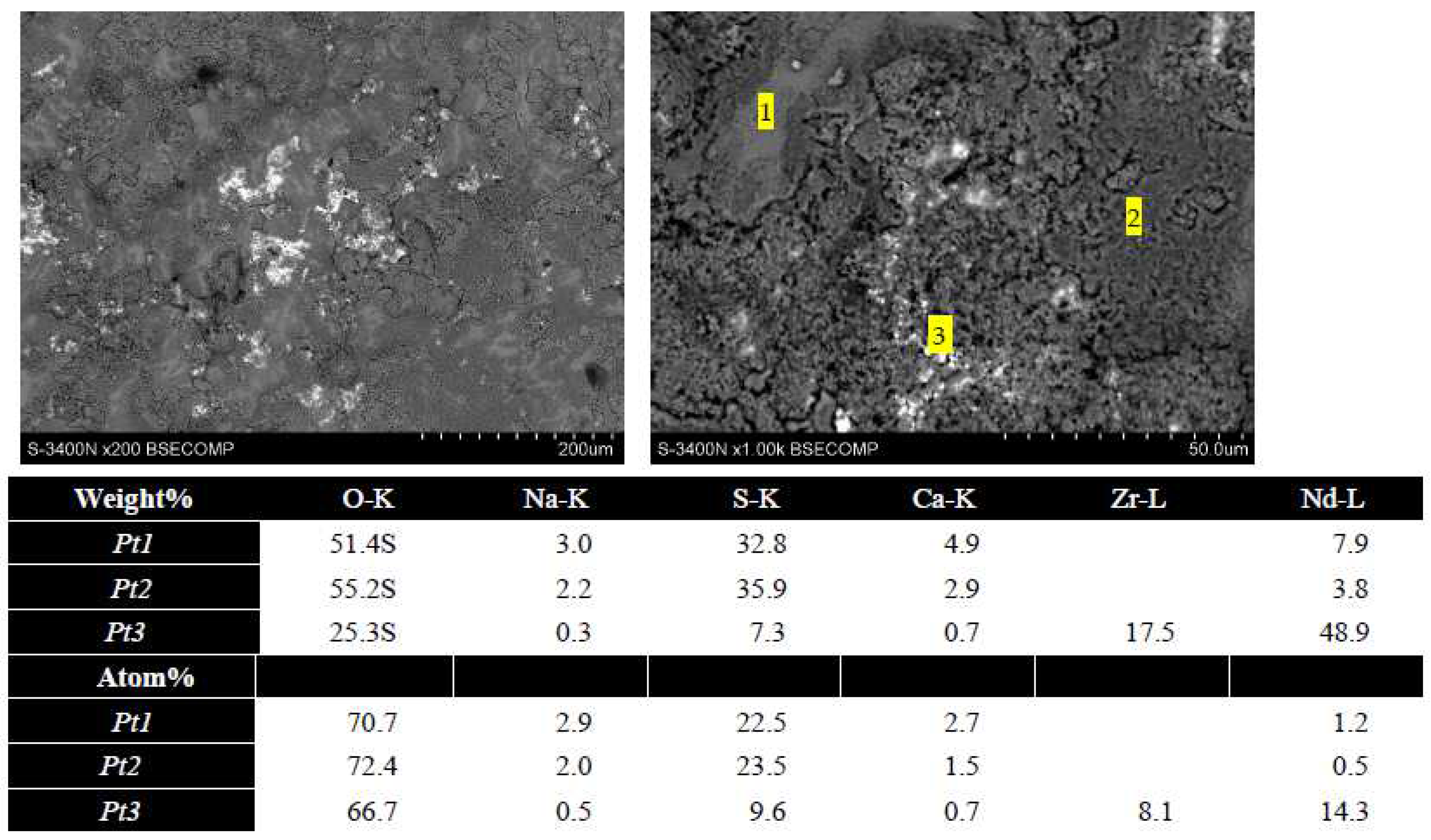
3.2.2. Hot Corrosion in a Mixture of 50/50 Mole Present of MgSO4 and Na2SO4

A subsequent hot corrosion test was conducted utilizing a mixture of sulfates (Na2SO4 + MgSO4) 50/50 mole at a temperature of 900 °C. X-ray diffraction was performed at intervals of 5, 10, 15, and 20 h during the cyclic hot corrosion tests to analyse the phase changes in the TBC sample’s topcoat. Figure 6 presents the XRD results of the phase transformation of the GZ (gadolinium zirconate) sample. The results indicate that the GZ sample maintained its stable cubic phase throughout the initial cycle of hot corrosion (5 h), with no observed phase changes. The phase changes within the TBC samples were subsequently monitored following the second cycle of tests. Notably, the TBC sample containing GZ, which initially exhibited complete stability in the pyrochlore cubic phase before the hot corrosion tests, underwent phase transformations. Specifically, the formation of m-ZrO2 (ICDD card no. 81-1549), Gd(SO4)3 (ICDD card no. 81-1549), Gd2O3 (ICDD card no. 86-2477) and Gd2O2SO4 (ICDD card no. 81-1549) phases were observed in the TBC sample. These findings underscore the susceptibility of the GZ-based TBC to phase alterations under the conditions of the hot corrosion tests in deposits of mixed MgSO4 and Na2SO4 salts (contrary to hot corrosion in pure MgSO4 salt or pure Na2SO4 salt [32].
At the specified temperature, the sulfates salt mixture composed of Na2SO4 and MgSO4 exhibits a significantly higher reactivity towards the coatings. Through XRD analysis of the GZ topcoat, it has been determined that the formation of the observed phases can be attributed to specific reactions induced by this aggressive sulfate mixture. The chemical transformations leading to the formation of these phases within the GZ topcoat are as follows.
2Gd2Zr2O7 + 6Na2SO4 → Gd2O2SO4 + Gd2(SO4)2 + 4 m-ZrO2 + 2SO3 + 6Na2O
Gd2Zr2O7 + MgSO4 → Gd2O2SO4 + MgO + m-ZrO2
These reactions illustrate the chemical transformations occurring within the TBC system when exposed to the aggressive sulfate mixture, leading to the observed phase changes in the GZ topcoat.
The analysis of the top surface morphology of the Gd2Zr2O7 TBC system shown in Figure 7 revealed the presence of sulfur-containing compounds with gadolinium, which suggests the presence of sulphate and oxy sulphate of gadolinium.
The phase composition analysis of the topcoat for Sm2Zr2O7 is illustrated in Figure 8 following cyclic hot corrosion tests conducted at an elevated temperature of 900 °C in the presence of Na2SO4 + MgSO4. The results indicate the formation of various corrosion products during the corrosion process. After subjecting the Sm2Zr2O7 ceramic topcoat to hot corrosion conditions at 900 °C, the analysis revealed the formation of multiple corrosion products. These include m-ZrO2 (ICDD card no. 83-0944), MgO (ICDD card no. 75-0497), Sm2O3 (ICDD card no. 84-1878 and 86-2979), Sm2O2SO4 (ICDD card no. 30-1105), and Sm2(SO4)3 (ICDD card no. 39-0304). These phase structures signify the transformations that occurred during the hot corrosion process.
In Figure 9, the analysis of the top surface morphology of the Sm2Zr2O7 TBC system revealed similar effects as earlier—the presence of sulfur-rich compounds with samarium, which suggests the presence of sulfide and oxysulfide of samarium.
Similarly, as it can be seen in the Figure 10, for the Nd2Zr2O7 ceramic topcoat, the hot corrosion tests at 900 °C and a mixture of (MgSO4 + Na2SO4) in a 50/50 mol percent ratio was involved in the corrosion process which resulted in the formation of specific corrosion products. These include m-ZrO2 (ICDD card no. 74-0815), MgO (ICDD card no. 75-0497), Na2O (ICDD card no. 74-0900), and Nd2(SO4)3 (ICDD card no. 83-2244). The presence of these corrosion products highlights the complex chemical reactions and phase transformations that took place during the hot corrosion of the Nd2Zr2O7 ceramic topcoat.
The analysis of the top surface morphology of the Nd2Zr2O7 TBC system also revealed the presence of sulfur-rich compounds, which suggests the presence of sulfide and oxysulfide of neodymium, as shown in Figure 11.
During the hot corrosion process at 900 °C for 24 h in the presence of sulfur-containing compounds, similar corrosion products were observed in the La2Zr2O7 coating. Notably, the formation of the oxysulfate La2O2SO4 was detected within the coating. The reaction responsible for the generation of this species can be represented as:
La2Zr2O7 + MgSO4 → La2O2SO4 + MgO + 2ZrO2
It has been reported in previous studies that at these elevated temperatures of 900 °C, the dominant species formed as a result of the reaction is the oxysulfate (La2O2SO4) rather than the sulfate La2(SO4)3 [33].
The presented results of XRD analysis of corrosion product phase constituents reveal visible differences in the hot corrosion behaviour of zirconates related to different types of rare earth elements and diverse compositions of the corrosive environment.
Firstly, the impact of a corrosive environment will be analysed. The melting point of Na2SO4 salt is much lower than MgSO4, i.e., 884 °C and 1124 °C, respectively. This indicates that sodium sulphate deposits should be more active and corrosive than magnesium sulphate. Unfortunately, this suggestion was not confirmed in this investigation or comparative work [32].
A different situation was observed in the case of a mixture of both sulphate salts Na2SO4 + MgSO4. Two versions of the Na2SO4 + MgSO4 phase diagram were found in the literature [34]. In the first, the Mg3Na2(SO4)4 (3MgSO4 + Na2(SO4)) melts congruently at about 822 °C and forms a eutectic with the solid MgSO4 compound at 807 °C and 21 mol.% Na2SO4. In the second, the author suggests that this compound melts incongruently into MgSO4 plus a liquid of 28 mol.% Na2SO4 at the same temperature. These analyses agree reasonably well regarding the eutectic temperature of L ↔ Mg3Na2(SO4)4 + Na2SO4, at around 660 °C. In [35], this temperature was calculated as 666 °C.
The formation of a low-temperature-melting Mg3Na2(SO4)4 + Na2SO4 eutectic compound is the reason for the stronger effect of corrosion, expressed overall, for rare earth elements zirconates, as reactions 6 and 7. Those reactions explain the formation of sulphide and oxysulphides of rare earth elements and the presence of monoclinic zirconia and oxides of magnesium and sodium. The presence of rare earth oxides can be caused by the thermal decomposition of zirconates accelerated by the presence of eutectic sulphate.

4. Conclusions

  • The hot corrosion environment based on a mixture of sodium and magnesium sulphate salts is more aggressive than pure salts. This aggressivity increases due to the formation of low-temperature-melting eutectic Na2SO4 + (3MgSO4 × Na2SO4), melted at 666 °C.
  • This aggressivity was expressed by the formation of sulphate and oxysulphate of rare earth elements presented in rare earth zirconates, not detected in the case of hot corrosion of the same zirconates in pure-salt-deposit environments.
  • However, the observed phenomenon of zirconate decomposition was relatively low at this scale, which showed that the analysed zirconates of rare earth elements had satisfactory resistance in this type of corrosive environment.
  • From among these zirconates, the least resistant to the Na2SO4 + (3MgSO4 × Na2SO4)-based corrosive environment was the Gd2Zr2O7 TBC system. Better behaviour was detected for Sm2Zr2O7 and Nd2Zr2O7, which suggests that an increasing cation size is a factor that determines the corrosion resistance, as suggested by the results obtained in [36].

Author Contributions

Conceptualization, M.J.K. and G.M.; Methodology, M.J.K.; Software, M.J.K.; Formal analysis, M.J.K.; Investigation, M.J.K.; Data curation, M.J.K. and P.O.; Writing—original draft, M.J.K.; Writing—review & editing, G.M. and A.I.; Visualization, M.M.; Supervision, G.M.; Project administration, T.P. All authors have read and agreed to the published version of the manuscript.

Funding

Publication supported by the excellence initiative—Research university program implemented at the Silesian university of technology, one-year 2022 under the project No. 32/014/SDU/10-22-53.

Institutional Review Board Statement

Not applicable.

Informed Consent Statement

Not applicable.

Data Availability Statement

The Data will be available from corresponding author on reasonable request.

Acknowledgments

Publication supported by the excellence initiative—Research university program implemented at the Silesian university of technology, one-year 2022 under the project No. 32/014/SDU/10-22-53.

Conflicts of Interest

The authors declare no conflict of interest. All authors are agree to publish the current version of article.

References

  1. Doleker, K.M.; Ozgurluk, Y.; Kahraman, Y.; Karaoglanli, A.C. Oxidation and hot corrosion resistance of HVOF/EB-PVD thermal barrier coating system. Surf. Coatings Technol. 2021, 409, 126862. [Google Scholar] [CrossRef]
  2. Iqbal, A.; Moskal, G.; Głowacka, H.M.; Pawlik, T.; Cavalerio, A. Phase decompositions of Gd2Zr2O7+ 8YSZ TBC systems under the condition of long-term high-temperature oxidation. Surf. Coat. Technol. 2023, 462, 129471. [Google Scholar] [CrossRef]
  3. Schlichting, K.W.; Padture, N.P.; Jordan, E.H.; Gell, M. Failure modes in plasma-sprayed thermal barrier coatings. Mater. Sci. Eng. A 2003, 342, 120–130. [Google Scholar] [CrossRef]
  4. Hutchinson, J.W.; Mahalle, A.M. Thermal barrier coating materials for SI engine. Ceram. Int. 2002, 50, 179–184. [Google Scholar] [CrossRef] [Green Version]
  5. Mehta, A.; Vasudev, H.; Singh, S.; Prakash, C.; Saxena, K.K.; Linul, E.; Buddhi, D.; Xu, J. Processing and Advancements in the Development of Thermal Barrier Coatings: A Review. Coatings 2022, 12, 1318. [Google Scholar] [CrossRef]
  6. Thakare, J.G.; Pandey, C.; Mahapatra, M.M.; Mulik, R.S. Thermal Barrier Coatings—A State of the Art Review. Met. Mater. Int. 2021, 27, 1947–1968. [Google Scholar] [CrossRef]
  7. Moskal, G. Thermal barrier coatings: Part 1—Characteristics of microstructure and properties, generation and directions of development of bond. Arch. Mater. Sci. 2007, 28, 100–112. [Google Scholar]
  8. Karlsson, A.M.; Xu, T.; Evans, A.G. The effect of the thermal barrier coating on the displacement instability in thermal barrier systems. Acta Mater. 2002, 50, 1211–1218. [Google Scholar] [CrossRef] [Green Version]
  9. Dhomne, S.; Mahalle, A.M. Thermal barrier coating materials for SI engine. J. Mater. Res. Technol. 2019, 8, 1532–1537. [Google Scholar] [CrossRef]
  10. Guo, L.; Li, B.; Cheng, Y.; Wang, L. Composition optimization, high-temperature stability, and thermal cycling performance of Sc-doped Gd2Zr2O7 thermal barrier coatings: Theoretical and experimental studies. J. Adv. Ceram. 2022, 11, 454–469. [Google Scholar] [CrossRef]
  11. Moskal, G.; Jucha, S.; Mikuśkiewicz, M.; Migas, D.; Jasik, A. Atypical decomposition processes of Sm2Zr2O7 + 8YSZ dual-phase TBCs during hot corrosion. Corros. Sci. 2020, 170, 108681. [Google Scholar] [CrossRef]
  12. Mohan, P.; Patterson, T.; Yao, B.; Sohn, Y. Degradation of thermal barrier coatings by fuel impurities and CMAS: Thermochemical interactions and mitigation approaches. J. Therm. Spray Technol. 2010, 19, 156–167. [Google Scholar] [CrossRef]
  13. Morelli, S.; Bursich, S.; Testa, V.; Bolelli, G.; Miccich, A. Surface & Coatings Technology CMAS corrosion and thermal cycling fatigue resistance of alternative thermal barrier coating materials and architectures: A comparative evaluation. Surf. Coat. Technol. 2022, 439, 128433. [Google Scholar] [CrossRef]
  14. Wei, Z.-Y.; Meng, G.-H.; Chen, L.; Li, G.-R.; Liu, M.-J.; Zhang, W.-X.; Zhao, L.-N.; Zhang, Q.; Zhang, X.-D.; Wan, C.-L.; et al. Progress in ceramic materials and structure design toward advanced thermal barrier coatings. J. Adv. Ceram. 2022, 11, 985–1068. [Google Scholar] [CrossRef]
  15. Evans, A.G.; Mumm, D.R.; Hutchinson, J.W. Mechanisms controlling the durability of thermal barrier coatings. Prog. Mater. Sci. 2001, 46, 505–553. [Google Scholar] [CrossRef]
  16. Chen, Z.; Cui, X.; Fang, Y.; Yan, C.; Wang, R.; Jing, Y.; Wang, X.; Jin, G.; Wang, X. Surface & Coatings Technology A comparative study on the hot corrosion behavior of plasma sprayed Sm/Gd doped La2Zr2O7/YSZ and Sm and Gd co-doped La2Zr2O7/YSZ coatings. Surf. Coat. Technol. 2023, 452, 129077. [Google Scholar] [CrossRef]
  17. Hossain, M.K.; Rubel, M.H.K.; Akbar, M.A.; Ahmed, M.H.; Haque, N.; Rahman, M.F.; Hossain, J.; Hossain, K.M. A review on recent applications and future prospects of rare earth oxides in corrosion and thermal barrier coatings, catalysts, tribological, and environmental sectors. Ceram. Int. 2022, 48, 32588–32612. [Google Scholar] [CrossRef]
  18. Jones, R.L. Some Aspects of the Hot Corrosion of Thermal Barrier Coatings. J. Therm. Spray Technol. 1997, 6, 77–84. [Google Scholar] [CrossRef] [Green Version]
  19. Iqbal, A.; Moskal, G. Recent Development in Advance Ceramic Materials and understanding the Mechanism of Thermal Barrier Coating Degradation. Arch. Comput. Methods Eng. 2023, 1–42. [Google Scholar] [CrossRef]
  20. Ozgurluk, Y.; Doleker, K.M.; Ozkan, D.; Ahlatci, H.; Karaoglanli, A.C. Cyclic hot corrosion failure behaviors of EB-PVD TBC systems in the presence of sulfate and vanadate molten salts. Coatings 2019, 9, 166. [Google Scholar] [CrossRef] [Green Version]
  21. Liu, H.F.; Xiong, X.; Li, X.B.; Wang, Y.L. Hot corrosion behavior of Sc2O3-Y2O3-ZrO2 thermal barrier coatings in presence of Na2SO4+V2O5 molten salt. Corros. Sci. 2014, 85, 87–93. [Google Scholar] [CrossRef]
  22. Jamali, H.; Mozafarinia, R.; Shoja-Razavi, R.; Ahmadi-Pidani, R. Comparison of hot corrosion behaviors of plasma-sprayed nanostructured and conventional YSZ thermal barrier coatings exposure to molten vanadium pentoxide and sodium sulfate. J. Eur. Ceram. Soc. 2014, 34, 485–492. [Google Scholar] [CrossRef]
  23. Lashmi, P.G.; Majithia, S.; Shwetha, V.; Balaji, N.; Aruna, S.T. Improved hot corrosion resistance of plasma sprayed YSZ/Gd2Zr2O7 thermal barrier coating over single layer YSZ. Mater. Charact. 2019, 147, 199–206. [Google Scholar] [CrossRef]
  24. Holländer, C.; Kiliani, S.; Stamm, W.; Lüsebrink, O.; Harders, H.; Wessel, E.; Müller, M.; Singheiser, L. Hot corrosion of TBC—Coated components upon combustion of low–sulfur fuels. Mater. Corros. 2021, 72, 1643–1655. [Google Scholar] [CrossRef]
  25. Kamal, S.; Jayaganthan, R.; Prakash, S. High temperature cyclic oxidation and hot corrosion behaviours of superalloys at 900 °C. Bull. Mater. Sci. 2010, 33, 299–306. [Google Scholar] [CrossRef] [Green Version]
  26. Zhang, W.; Sharghi-moshtaghin, R. Understanding the Type II Corrosion Mechanism. Metall. Mater. Trans. A 2021, 52, 1492–1502. [Google Scholar] [CrossRef]
  27. Salehnasab, B.; Poursaeidi, E.; Mortazavi, S.A.; Farokhian, G.H. Hot corrosion failure in the first stage nozzle of a gas turbine engine. Eng. Fail. Anal. 2016, 60, 316–325. [Google Scholar] [CrossRef]
  28. Shifler, D.A. The Increasing Complexity of Hot Corrosion. ASME. J. Eng. Gas Turbines Power 2017. [Google Scholar] [CrossRef]
  29. Shifler, D. Understanding High Temperature Corrosion—Key To Energy Efficiency? Corrosion 2016, 2235. Available online: http://corrosionjournal.org/doi/10.5006/2235 (accessed on 24 July 2023).
  30. Lawson, M.G.; Pettit, F.S.; Blachere, J.R. Hot corrosion of alumina. J. Mater. Res. 1993, 8, 1964–1971. [Google Scholar] [CrossRef]
  31. Migas, D.; Moskal, G.; Jucha, S. Hot corrosion behavior of double-phase Nd2Zr2O7-YSZ thermal barrier coatings. Surf. Coat. Technol. 2022, 449, 128955. [Google Scholar] [CrossRef]
  32. Liu, Z.G.; Ouyang, J.H.; Zhou, Y.; Li, S. High-temperature hot corrosion behavior of gadolinium zirconate by vanadium pentoxide and sodium sulfate in air. J. Eur. Ceram. Soc. 2010, 30, 2707–2713. [Google Scholar] [CrossRef]
  33. Marple, B.R.; Voyer, J.; Thibodeau, M.; Nagy, D.R.; Vassen, R. Hot corrosion of lanthanum zirconate and partially stabilized zirconia thermal barrier coatings. J. Eng. Gas Turbines Power 2006, 128, 144–152. [Google Scholar] [CrossRef] [Green Version]
  34. Ginsberg, A.S. Über die Verbindungen von Magnesium- und Natriumsulfat. Z. Für Anorg. Chem. 1909, 61, 122–136. [Google Scholar] [CrossRef] [Green Version]
  35. Wang, M.; Sundman, B.O. Thermodynamic Assessment of the Al-Ni system. J. Am. Ceram. Soc. 2000, 21, 6–18. [Google Scholar] [CrossRef]
  36. Poerschke, D.L.; Levi, C.G. Effects of cation substitution and temperature on the interaction between thermal barrier oxides and molten CMAS. J. Eur. Ceram. Soc. 2015, 35, 681–691. [Google Scholar] [CrossRef]
Figure 1. Overall powder surface view and morphology: (a) Gd2Zr2O7; (b) Sm2Zr2O7; (c) Nd2Zr2O7.
Coatings 13 01311 g001
Figure 2. The powder XRD analysis: (a) Gd2Zr2O7; (b) Sm2Zr2O7; (c) Nd2Zr2O7.
Coatings 13 01311 g002
Figure 3. SEM images of as-deposit topcoats of (a) Gd2Zr2O7; (b) Sm2Zr2O7; (c) Nd2Zr2O7.
Coatings 13 01311 g003
Figure 4. Macrographs of coatings after hot corrosion tests in MgSO4 at 1000 °C.
Coatings 13 01311 g004
Figure 5. XRD patterns of topcoats after hot corrosion in MgSO4 at 1000 °C for 24 h(a) Gd2Zr2O7; (b) Sm2Zr2O7; (c) Nd2Zr2O7.
Coatings 13 01311 g005
Figure 6. XRD patterns of Gd2Zr2O7 topcoat as-deposited and after hot corrosion at 900 °C for 5 h, 10 h, 15 h, and 20 h in the presence of Na2SO4 + MgSO4.
Coatings 13 01311 g006
Figure 7. The top surface of the Gd2Zr2O7 TBC system after hot corrosion in MgSO4 + Na2SO4 environment for 20 h.
Coatings 13 01311 g007
Figure 8. XRD patterns of Sm2Zr2O7 topcoat as-deposited and after hot corrosion at 900 °C for 5 h, 10 h, 15 h, and 20 h in the presence of Na2SO4 + MgSO4.
Coatings 13 01311 g008
Figure 9. The top surface of the Sm2Zr2O7 TBC system after hot corrosion in a MgSO4 + Na2SO4 environment for 20 h.
Coatings 13 01311 g009
Figure 10. XRD patterns of Nd2Zr2O7 topcoat as-deposited and after hot corrosion at 900 °C for 5 h, 10 h, 15 h, and 20 h in the presence of Na2SO4 + MgSO4.
Coatings 13 01311 g010
Figure 11. The top surface of the Nd2Zr2O7 TBC system after hot corrosion in a MgSO4 + Na2SO4 environment for 20 h.
Coatings 13 01311 g011
Table 1. The chemical composition of the IN 625 substrate alloy [31].
Wt%NiCrFeMoCoNbAlMnSiTiPCS
Inconel 62560.721.674.278.960.073.560.140.070.080.180.0070.010.0003
Table 2. Parameters of the TBC coating spraying process.
ParametersPowder Type
Gd2Zr2O7Sm2Zr2O7Nd2Zr2O7
Burner typeF4MBF4MBF4MB
Argon [L/min]404040
Hydrogen [L/min]101010
Powder carrier2.62.62.6
Powder feeding151515
Current [A]600600600
Arc voltage [V]61.6–62.361.6–62.361.6–62.3
Burner power [kW]37.2–38.137.2–38.137.2–38.1
Mixing606060
Rotation [RPM]120120120
Instrument diameter150150150
Feed [mm/s]101010
Distance [mm]100100100
Number of program cycles202020
Disclaimer/Publisher’s Note: The statements, opinions and data contained in all publications are solely those of the individual author(s) and contributor(s) and not of MDPI and/or the editor(s). MDPI and/or the editor(s) disclaim responsibility for any injury to people or property resulting from any ideas, methods, instructions or products referred to in the content.

