Article

Study on the Anisotropy of Triply Periodic Minimal Surface Porous Structures

1
School of Mechanical and Energy Engineering, Guangdong Ocean University, Yangjiang 529500, China
2
School of Mechanical and Automotive Engineering, South China University of Technology, Guangzhou 510641, China
*
Author to whom correspondence should be addressed.
Coatings 2023, 13(7), 1206; https://doi.org/10.3390/coatings13071206
Submission received: 8 June 2023 / Revised: 26 June 2023 / Accepted: 26 June 2023 / Published: 5 July 2023
(This article belongs to the Special Issue Recent Development in Post-processing for Additive Manufacturing)

Abstract

:
Because their topological structures have certain crystallographic symmetry, there is anisotropy in triply periodic minimal surface (TPMS) porous structures. Anisotropy can affect the mechanical properties of porous structures; thus, it is necessary to research the anisotropy of TPMS structures. In this study, based on quaternionic three-dimensional rotation, TPMS structures were rotated around three crystal directions: [100], [110], and [111]. The mechanical anisotropy behaviors of TPMS porous structures, including gyroid, diamond, primitive, and I-graph-wrapped package (IWP) graph surfaces, were studied through finite element analysis (FEA). The FEA results show that the anisotropy of the IWP structure with rotation in the [110] direction was the most significant, and its relative elastic modulus increased by 275.33% when the IWP was rotated 60° in the [110] direction. These results indicate that the uniaxial compression performance of TPMS structures can be significantly improved by using structural anisotropy. However, it should be noted that due to this significant anisotropy, the performance of such structures will significantly decrease in specific directions. For example, after the primitive structure was rotated 60° in the [111] and [110] directions, its relative elastic modulus decreased by 72.66% and 77.6%, respectively. Therefore, it was necessary to reasonably consider the bearing capacity in fragile directions under complex working conditions. Based on the anisotropy of TPMS, gradient TPMS structures with three rotation angles were designed and manufactured using selective laser melting technology. The compressive results show that multi-peaks appeared in the primitive structure with gradient rotation in the [111] direction from 0° to 40°, and step-by-step behaviors were observed in the IWP structure with gradient rotation in the [110] direction from 0° to 60°. This result shows that the yielding platform can be enhanced using gradient rotation designation based on the anisotropy of TPMS porous structures.

1. Introduction

Functionally graded materials (FGMs) feature changes in their material composition or structural characteristics. There are many FGMs in the biological structures of nature, such as bones [1], bamboo [2], hedgehog spines [3], and coral [4]. These FGMs have the characteristics of a light mass, high specific strength, and significant energy absorption, and they are the source of bionic designs for aerospace, biomedicine, radiators, electromagnetic fields, and acoustics. To imitate FGMs in nature, the structural characteristics of FGMs were analyzed and classified into six types: composition gradient, arrangement gradient, distribution gradient, dimension gradient, orientation gradient, and interface gradient structures [5].
The TPMS porous structure is one potential FGM structure that can be generated quickly using trigonometric functions [6]. The most common TPMS structures include gyroid, diamond, primitive, and IWP structures. The elastic modulus, yield strength, and plateau stress of a shell gyroid porous structure grow with increases in the number of circumferential cells or decreases in the number of radial cells under compression loading [7]. Cell type also has a significant effect on the compressive properties of porous structures. A Ti6Al4V lattice can be produced with an elastic modulus equivalent to that of real bone [8] by specifying different structural parameters, including cell type, support size, and porosity. In one study, the original opening diameter of the primitive structure was redefined, and two new structures were designed to compare with the new primitive lattice. It was found that the mechanical properties and energy absorption of the P-lattice structure with a small opening diameter structure were better than those of the other structures with larger opening sizes [9]. The measured mechanical properties and energy absorption capacity of Ti6Al4V gradient samples with different thicknesses show that the TPMS samples with constant thicknesses have suitable stiffness, strength, and energy absorption capacity, whereas graded thickness samples avoid large stress fluctuations, and their elastic moduli and cumulative energy absorption values are higher than those of the samples with constant thicknesses [10]. Using digital image correlation (DIC) technology, the compressive behavior of TPMSs was studied, and it was found that the mechanical properties of TPMS structures can be controlled using the gradient function [11].
According to an analysis of TPMS porous structures, the mechanical properties of TPMS porous structures are mainly related to their topological structure, porosity, thickness, element size, and gradient structures. Additionally, anisotropy also plays an important role in influencing the mechanical properties of porous structures [12], and it is necessary to take orientation direction into account when developing bone scaffolds. The anisotropic behavior of cubic and cellular porous structures on their energy absorption and compressive strength has been studied, and the results show that cellular porous structures have the highest energy absorption density in the first direction (the compression direction parallel to the struts) and the largest compressive strength in the second direction (where the structure was rotated 90° around the x-axis) [13]. The anisotropic behavior of gyroid structures was analyzed using the finite element method and simplified structural analysis method [14], demonstrating that the anisotropy of gyroid structures has a certain symmetrical relationship in its crystallography that corresponds to the symmetrical relationship of space groups in crystallography.
The strut-diamond, sheet-Schwartz D, and sheet-gyroid structures were rotated and investigated, and the mechanical properties of these three structures all showed dependence on orientation [15]. The intensity of the anisotropy of the strut-based architecture was higher than that of the sheet-based TPMS, which highlights the superior strength and advantageous isotropic mechanical properties of sheet-based TPMS architectures relative to strut-based architectures. The anisotropy of gyroid cellular structures can be observed by changing their geometric parameters [16], and it was found that structural anisotropy, porosity, and loading direction are the main factors affecting the anisotropic elastic response of gyroid cellular structures. The effective properties and 3D spatial representation of the normalized effective shear moduli of TPMS sheet-based foams were analyzed using finite element modeling [17], and the results show that the modulus of a TPMS structure is different in several directions. The anisotropic elastic behaviors of TPMS-based scaffolds were analyzed using a combination of the numerical homogenization method and the analytical analysis approach [18]. The analysis indicates that diamond, gyroid, and Fischer-Koch S topologies are three-fold rotationally symmetrical. The Schwarz P and F-RD topologies have cubic symmetry. Statistical analysis of the symmetrical relations between TPMS structures [19] and indicated that the space groups of gyroid, diamond, primitive, and IWP are I4132, Fd 3 ¯ m, P m 3 ¯ m , and I m 3 ¯ m , respectively. These four TPMS structures are all cubic crystal systems.
The direction with weaker strength will cause the structure to prioritize failure in this direction. Therefore, in research on partial structural design, it is necessary to avoid or weaken anisotropy as much as possible. As a design method with variable thickness, TPMS [20] was proposed to achieve elastic isotropy from homogeneous anisotropic constitutive materials, and the anisotropy of TPMS can be avoided using this method. Nevertheless, the anisotropy of TPMS can be applied to construct FGM with a rotation structure. Some biomaterials are composed of anisotropic basic structural units, such as fibers, sheets, and vascular bundles. By adjusting the direction of these basic structural units, the local characteristics of the structure can be further controlled. The mechanical properties of the wood show a negative correlation with the off-axis angle of microfibers [21]. As the off-axis angle increases, its stiffness, elastic modulus, and strength gradually decrease. Gradient-oriented structures are also common in various impact-resistant biomaterials, such as natural defense armor in beetles [22], pangolins [23], and fish scales [24], as well as offensive weapons for mantis shrimp [25]. The purpose of a gradient-oriented structure is to maximize damage to opponents while minimizing damage to the tissue itself by adjusting the direction of local structures. However, there is a lack of research on the gradient orientation based on TPMS design.
In this research, the anisotropic behavior of TPMS porous structures was studied by finite element analysis, including gyroid, diamond, primitive, and IWP. These TPMS porous structures were rotated around the directions of the [100], [111], and [110] axes at multiple angles, and the relationship between rotation angle and elastic modulus was established. Based on the anisotropy of TPMS, a design method for gradient rotation structures was proposed and manufactured via selective laser melting (SLM) technology, and the compressive behavior and energy absorption of TPMS structures with gradient rotation were analyzed.

2. Materials and Methods

2.1. Crystallographic Symmetry Relationship of TPMS

The common generation functions of gyroid, diamond, primitive, and IWP in this research are shown in Functions (1)~(4).
F G y r o i d = sin ( 2 π x ) cos ( 2 π y ) + sin ( 2 π y ) cos ( 2 π z ) + sin ( 2 π z ) cos ( 2 π x ) t
F D i a m o n d = sin ( 2 π x ) sin ( 2 π y ) sin ( 2 π z ) + sin ( 2 π x ) cos ( 2 π y ) cos ( 2 π z ) + cos ( 2 π x ) sin ( 2 π y ) cos ( 2 π z ) + cos ( 2 π x ) cos ( 2 π y ) sin ( 2 π z ) t
F P r i m i t i v e = cos ( 2 π x ) + cos ( 2 π y ) + cos ( 2 π z ) t
F I W P = cos ( 2 π x ) cos ( 2 π y ) + cos ( 2 π y ) cos ( 2 π z ) + cos ( 2 π z ) cos ( 2 π x ) t
The pinch-off problem is an important defect of classic TPMS structures, leading to structural design problems and stress concentration [26], especially primitive and IWP. Based on previous research [27], the optimization functions of primitive and IWP are shown in Functions (5) and (6).
F P r i m i t i v e o p i m i z a t i o n = 10 × [ cos ( 2 π x ) + cos ( 2 π y ) + cos ( 2 π z ) ] 5 × F I W P t
F I W P o p t i m i z a t i o n = 10 × cos ( 2 π x cos ( 2 π y ) + cos ( 2 π y ) cos ( 2 π z ) + cos ( 2 π z ) cos ( 2 π x ) ] 5 × F p r i m i t i v e t
The relevant literature [19,28] shows that the porous structure of TPMS has specific crystallographic symmetry relations, as listed in Table 1. All of the porosity of TPMS was set to 85%.
To study the anisotropy of TPMS, the TPMS can be rotated around an axis by fixing the compression direction, and the compressive mechanical properties of TPMS can be analyzed based on different rotation angles. The difficulty lies in how to parameterize the rotating structure of porous three-dimensional space. In this section, a method for the rotating operation of TPMS in three-dimensional space is proposed. Some codes in the structural design steps are described as follows.

2.1.1. Quaternion Construction

The concept of a quaternion was proposed by Hamilton, and its most important application in 3D computer graphics is to describe the rotation of 3D structures. In Euler’s theorem, the rotation of all three-dimensional structures can be expressed by a rotation vector and rotation angle. Thus, the concept of a quaternion is also constructed according to the rotation axis and rotation angle. The rotation axis here is set as vector v = (vx, vy, vz), the crystal orientation is set as [x y z], and the rotation angle is set as θ (right-hand rule rotation). The following is an example of a 20° rotation around the [111] crystal orientation to illustrate the calculation code for a quaternion.
The quaternion construction code of [111]-20° is as follows:
  • axis = [111]; %Rotation axis, the crystal orientation is the [111] direction
  • theta = 20; %Rotation angle is 20°
  • axis = axis./norm(axis);
  • q = [cosd(theta/2) sind(theta/2)*axis(1) sind(theta/2)*axis(2) sind(theta/2)*axis(3)]
  • %Quaternion calculation.

2.1.2. Calculation of the Rotation Matrix

According to the concept of quaternion, the rotation matrix of a three-dimensional structure is constructed. The rotation matrix is constructed by a quaternion code, as follows:
R = q ( 1 ) ^ 2 + q ( 2 ) ^ 2 q ( 3 ) ^ 2     q ( 4 ) ^ 2 2 q ( 2 ) q ( 3 ) 2 q ( 1 ) q ( 4 ) 2 q ( 2 ) q ( 4 ) + 2 q ( 1 ) q ( 2 ) 2 q ( 2 ) q ( 3 ) + 2 q ( 1 ) q ( 4 ) q ( 1 ) ^ 2 q ( 2 ) ^ 2 + q ( 3 ) ^ 2 q ( 4 ) ^ 2 2 q ( 3 ) q ( 4 ) 2 q ( 1 ) q ( 2 ) 2 q ( 2 ) q ( 4 ) 2 q ( 1 ) q ( 3 ) 2 q ( 3 ) q ( 4 ) + 2 q ( 1 ) q ( 2 ) q ( 1 ) ^ 2 q ( 2 ) ^ 2 q ( 3 ) ^ 2 + q ( 4 ) ^ 2

2.1.3. Three-Dimensional Rotation Operation

The rotated point coordinate matrix is obtained by right-multiplying the structural point coordinates by the rotation matrix, as shown in the code below. Then, the rotated point coordinate matrix is substituted into the TPMS structure function to obtain the TPMS rotated 20° around the [111] crystal orientation.
Code:
  • x = x_ .* R(1,1) + y_ .* R(1,2) + z_ .* R(1,3);
  • y = x_ .* R(2,1) + y_ .* R(2,2) + z_ .* R(2,3);
  • z = x_ .* R(3,1) + y_ .* R(3,2) + z_ .* R(3,3);
Based on the above codes, we can construct TPMS structures that rotate around different crystal directions.

2.2. Crystallography Symmetry Analysis of TPMS

2.2.1. Gyroid

According to Table 1, the space group of the gyroid structure is I4132, and the space group number is 214. The symbol “I” indicates that the gyroid structure is a body-centered cubic lattice structure. The order for the space group is as follows: the first position represents the direction of the fundamental vector a, the second position represents the direction of the fundamental vector a + b + c, and the third position represents the direction of the fundamental vector a + b. That is, the first digit represents the direction of the fundamental vector [100], the second digit represents the direction of the fundamental vector [111], and the third digit represents the direction of the fundamental vector [110].
The symmetries of the gyroid are described below:
(1)
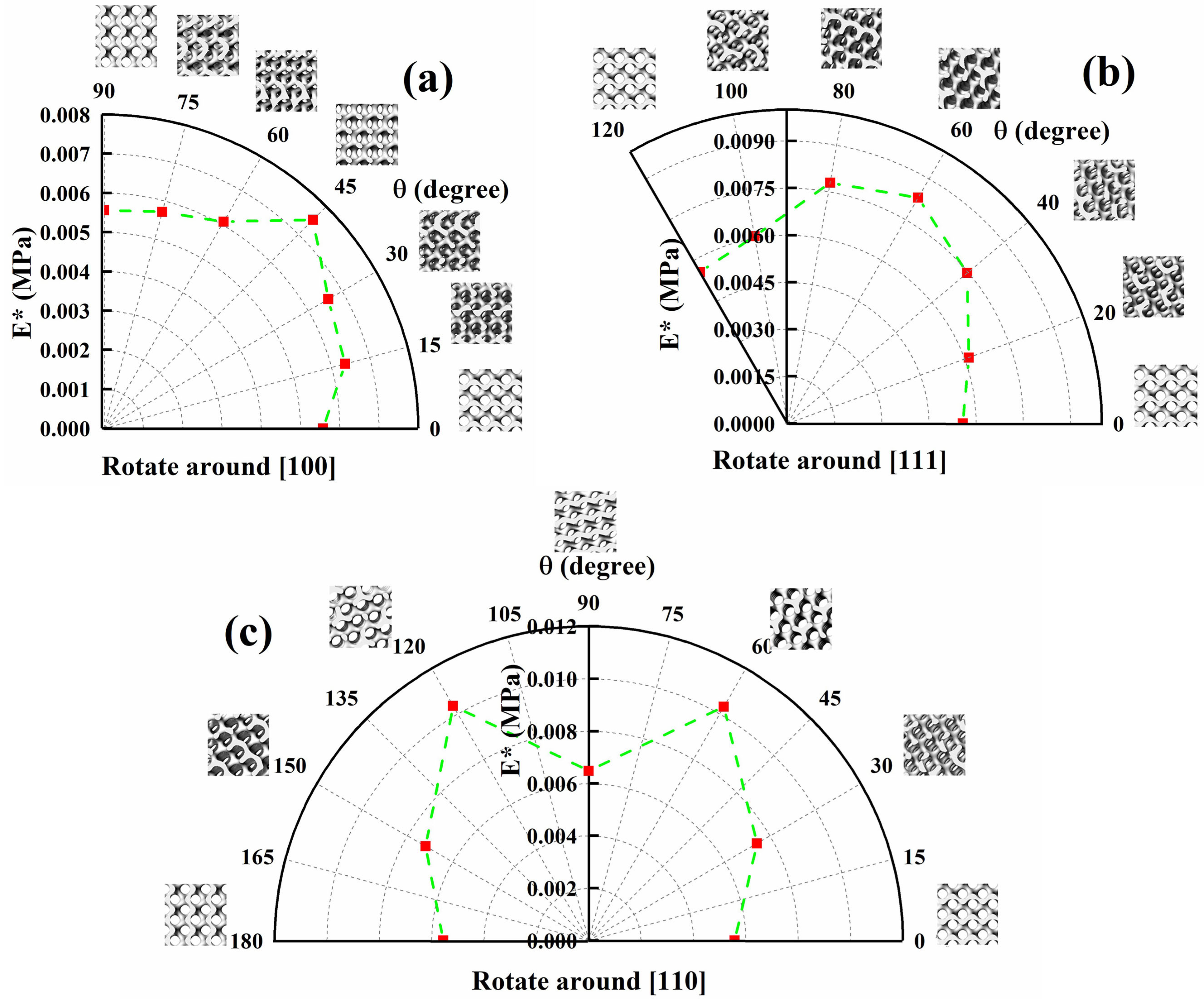
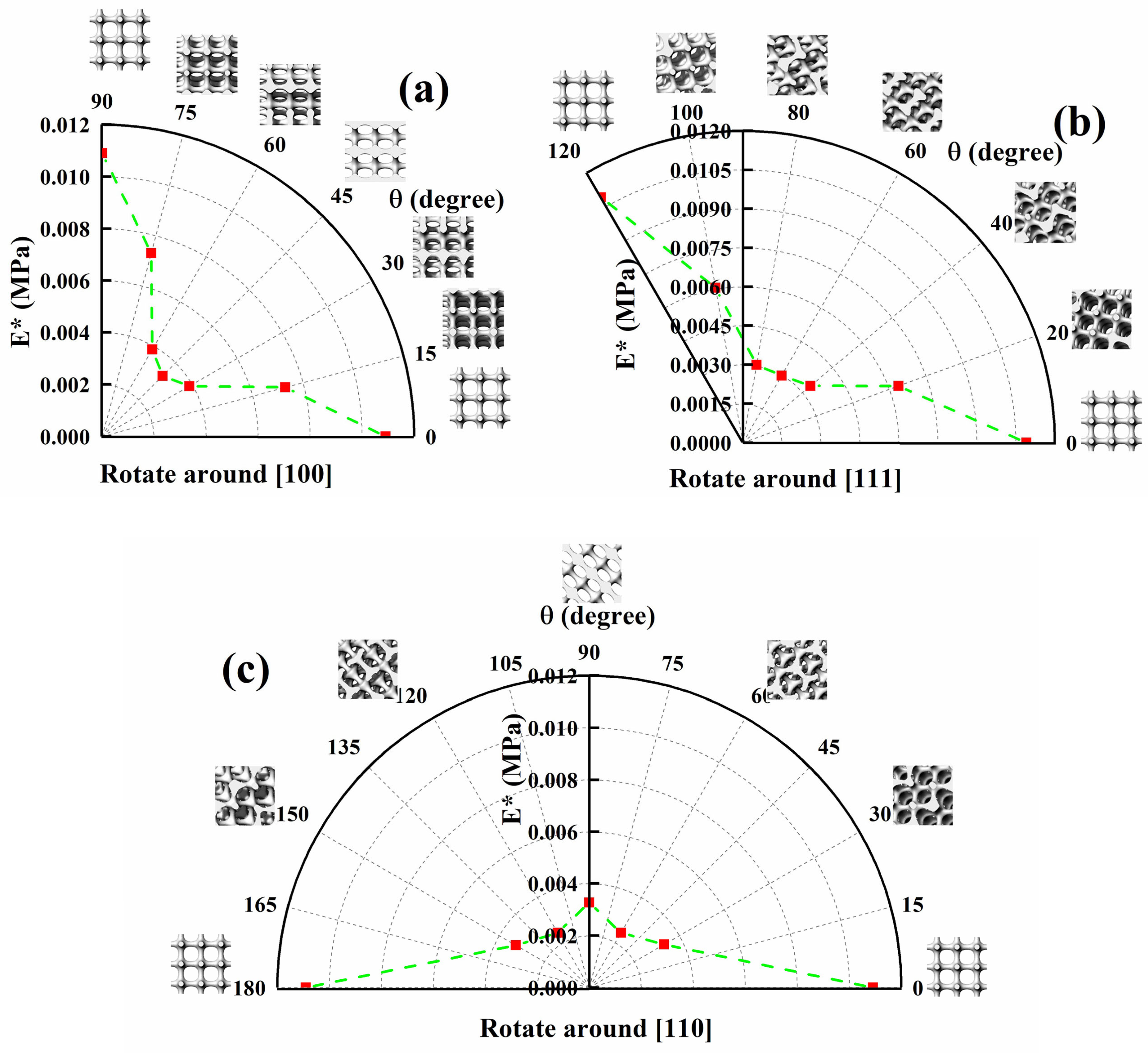
The gyroid has a quadratic helical axis in the [100] direction, with 2 π 4 helical symmetry, which illustrates that the same structure can be obtained by rotating 90° around the [100] direction. Therefore, the [100] direction was set as the rotation axis, and the rotation angle was set as follows: 0°, 15°, 30°, 45°, 60°, 75°, and 90°.
(2)
The gyroid has a third axis in the [111] direction, with 2 π 3 symmetry, which illustrates that the same structure can be obtained by rotating 120° around the [111] direction. Therefore, the rotation angle was set around the [111] direction as follows: 0°, 20°, 40°, 60°, 80°, 100°, and 120°.
(3)
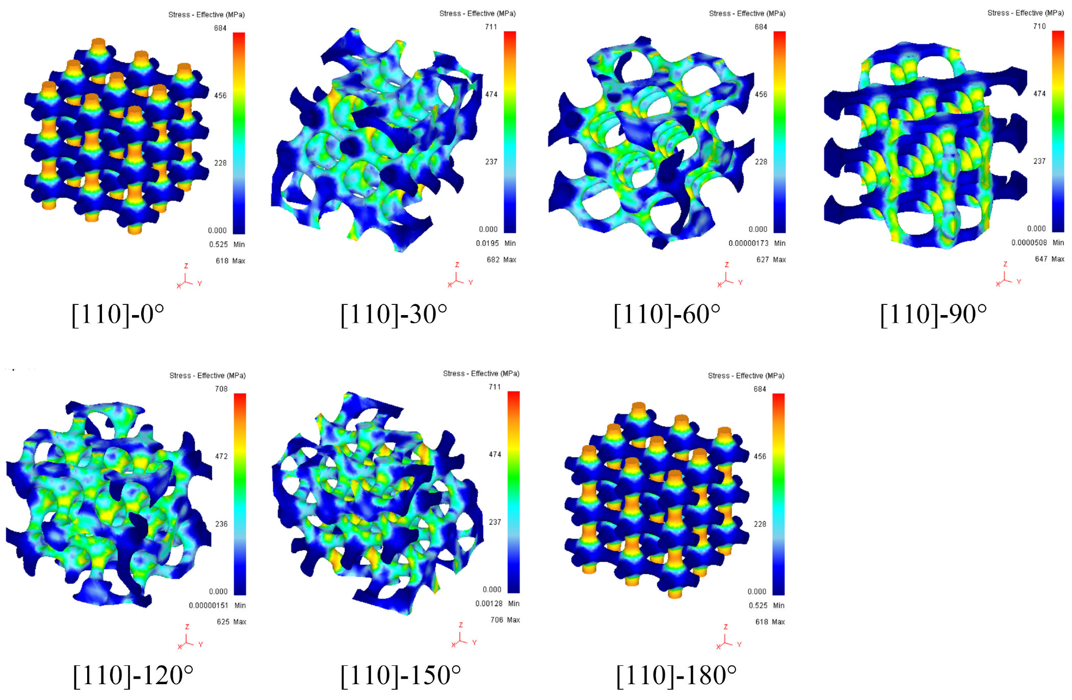
The gyroid has a second axis in the [110] direction and 2 π 2 symmetry, which illustrates that the same structure can be obtained by rotating 180° around the [110] direction. Therefore, the rotation angle was set around the [110] direction as follows: 0°, 30°, 60°, 90°, 120°, 150°, and 180°.
Based on the above analysis of the crystallographic symmetry of the gyroid and rotation operation code, the structures with different angles of rotation around different axes are designed for the study of the anisotropy of the gyroid.

2.2.2. Diamond

According to Table 1, the space group of the diamond structure is F 4 ¯ 3m. Here, the symbol “F” indicates that the diamond structure is a face-centered cubic lattice. The symmetry of a diamond structure is described below:
(1)
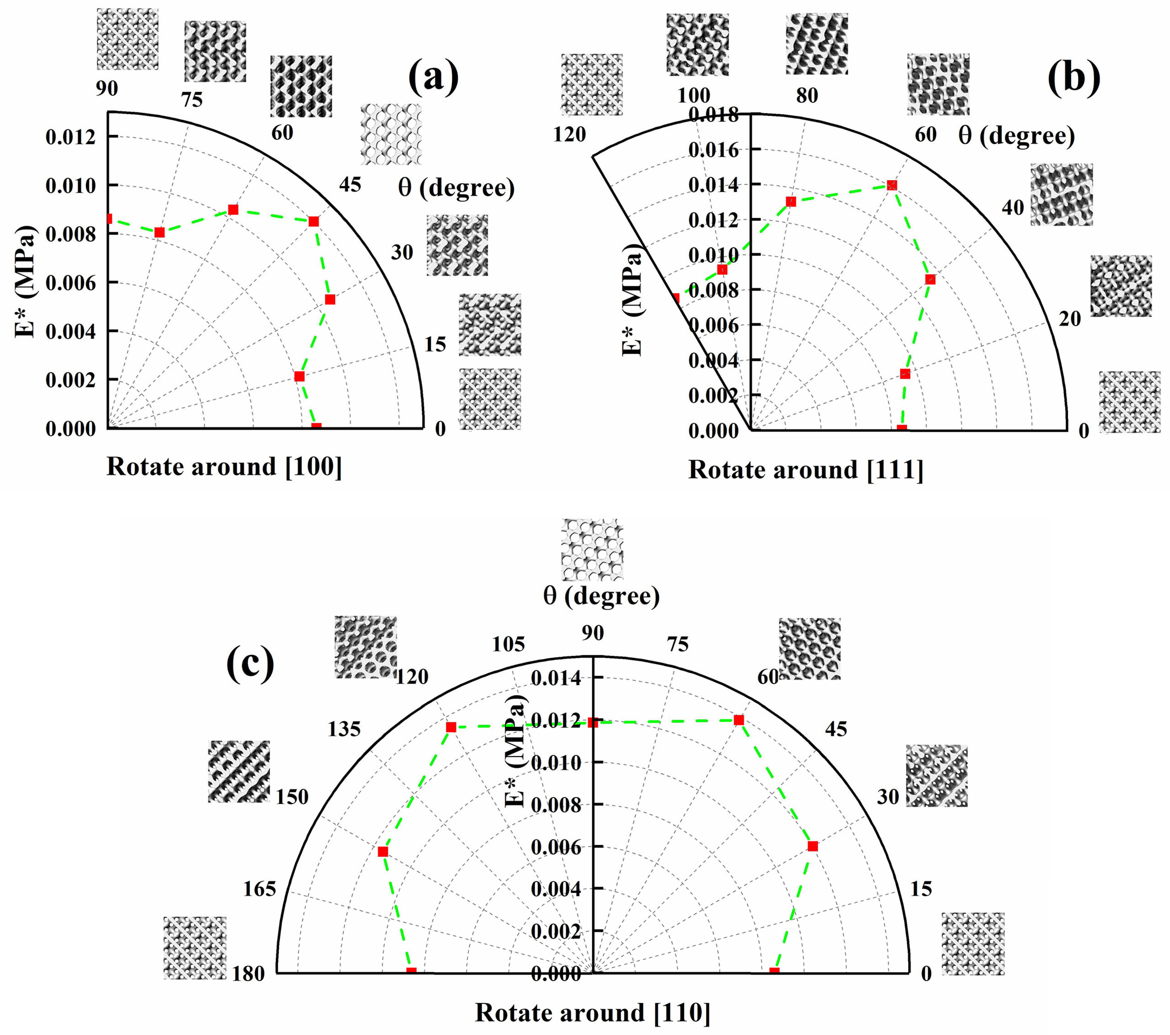
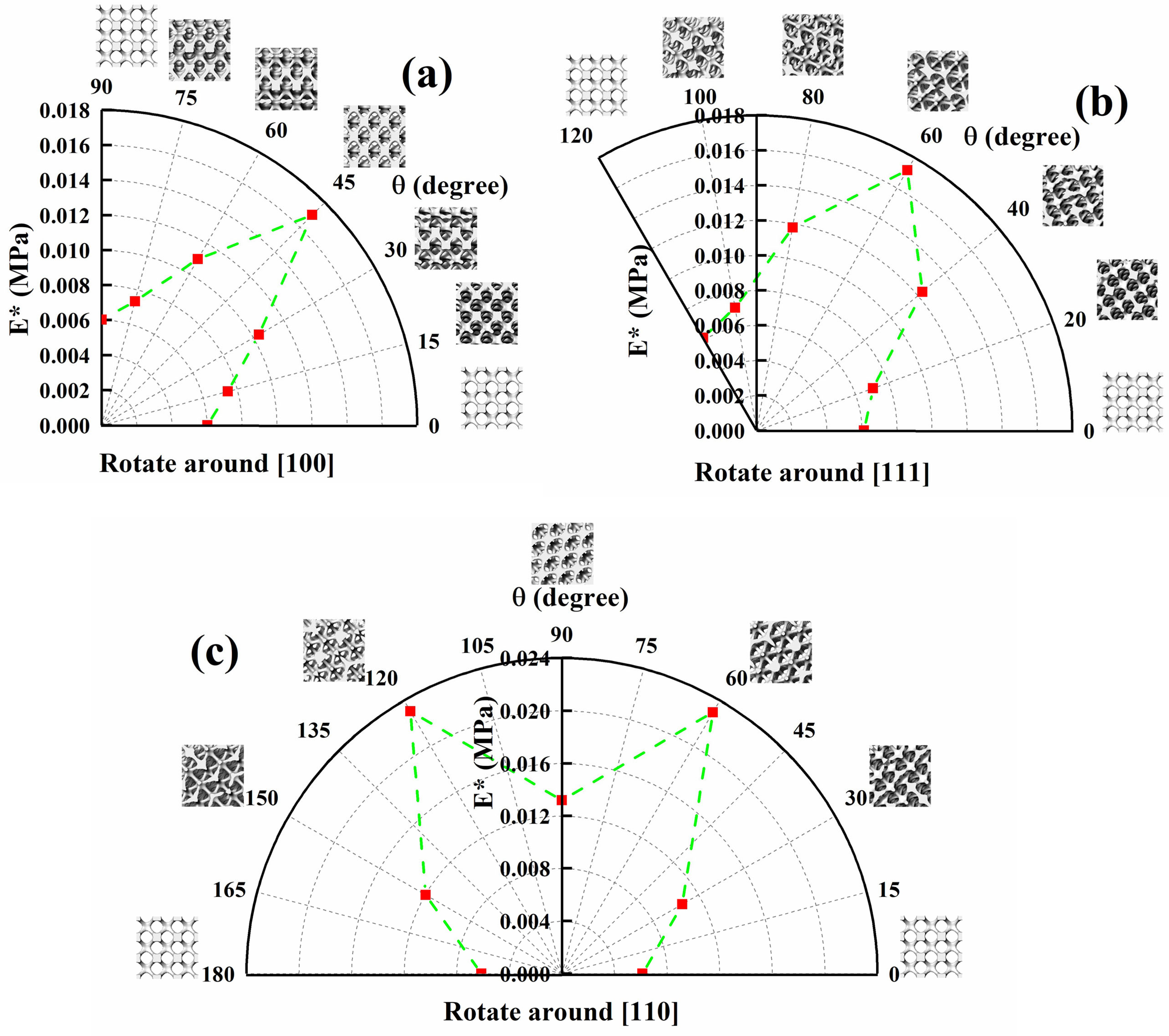
The diamond structure has a quartic inverted axis in the [100] direction and has the 2 π 4 inversional symmetry, which illustrates that the same structure can be obtained by rotating 90° around both the [100] direction and the reverse operation. Therefore, the rotation angle was set around the [100] direction as follows: 0°, 15°, 30°, 45°, 60°, 75°, and 90°.
(2)
The diamond structure has a third axis in the [111] direction and 2 π 3 symmetry, which illustrates that the same structure can be obtained by rotating 120° around the [111] direction, followed by the reverse operation. Therefore, the rotation angle was set around the [111] direction as follows: 0°, 20°, 40°, 60°, 80°, 100°, and 120°.
(3)
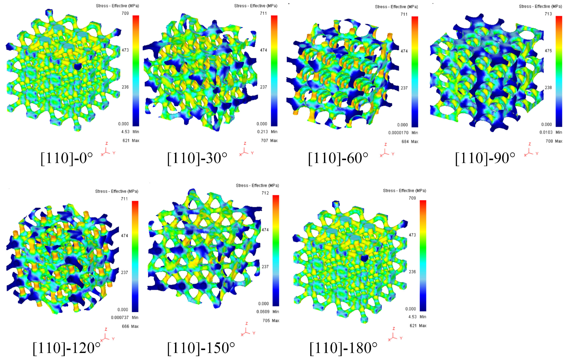
The diamond structure has a mirror symmetry plane m in the [110] direction, which means that the diamond has mirror symmetry. Additionally, mirror symmetry generally contains a quadratic axis; that is, it has the symmetry of 2 π 2 . This factor illustrates that the same structure can be obtained by rotating 180° around the [110] direction. The rotation angle was around the [110] direction as follows: 0°, 30°, 60°, 90°, 120°, 150°, and 180°.

2.2.3. Primitive

According to Table 1, the space group of the primitive structure is P 4 m 3 ¯ 2 m , and the symbol “P” indicates that the primitive structure is a lattice with a simple cubic structure. The symmetry of the primitive is described below:
(1)
The primitive has a quartic axis in the [100] direction, and its mirror symmetry plane is perpendicular to the fourth axis, which means the primitive has a mirror symmetry of 2 π 4 . This factor illustrates that the same structure can be obtained by rotating 90° around the [100] direction and using the mirror reflection operation. The rotation angle of the primitive was set around the [100] direction as follows: 0°, 15°, 30°, 45°, 60°, 75°, and 90°.
(2)
The primitive has a third inverted axis in the [111] direction and 2 π 3 inversional symmetry. This factor illustrates that the same structure can be obtained by rotating 120° around the [111] direction and using the central inversion operation. The rotation angle of the primitive was set around the [111] direction as follows: 0°, 20°, 30°, 40°, 60°, 80°, 100°, and 120°.
(3)
The primitive has a quadratic axis in the [110] direction, and its mirror symmetry plane is perpendicular to the secondary axis with 2 π 2 mirror symmetry. Therefore, the same structure can be obtained by rotating 180° around the [110] direction and performing the mirror reflection operation. The rotation angle of the primitive was set around the [110] direction as follows: 0°, 30°, 60°, 90°, 120°, 150°, and 180°.

2.2.4. IWP

According to Table 1, the space group of the IWP structure is I 4 m 3 ¯ 2 m , which is a cubic crystal system. The space group number is 229. Here, the symbol “I” indicates that the IWP structure is a body-centered cubic structure, and its symmetry is as follows:
(1)
IWP has a quartic axis in the [100] direction, and the mirror symmetry plane is perpendicular to the fourth axis. Therefore, IWP has a 2 π 4 rotational mirror symmetry. The same structure can be obtained by rotating 90° around the [100] direction and performing the mirror reflection operation. The rotation angle of IWP was set around the [100] direction as follows: 0°, 15°, 30°, 45°, 60°, 75°, and 90°.
(2)
IWP has a third inverted axis in the [111] direction and 2 π 3 inversional symmetry. Thus, the same structure can be obtained by rotating 120° around the [111] direction and performing the central inversion operation. The rotation angle of IWP was set around the [111] direction as follows: 0°, 20°, 30°, 40°, 60°, 80°, 100°, and 120°.
(3)
IWP has a quadratic axis in the [110] direction, and its mirror symmetry plane is perpendicular to the quadratic axis with a mirror symmetry of 2 π 2 . Therefore, the same structure can be obtained by rotating 180° around the [110] direction and performing the mirror reflection operation. The rotation angle of IWP was set around the [110] direction as follows: 0°, 30°, 60°, 90°, 120°, 150°, and 180°.

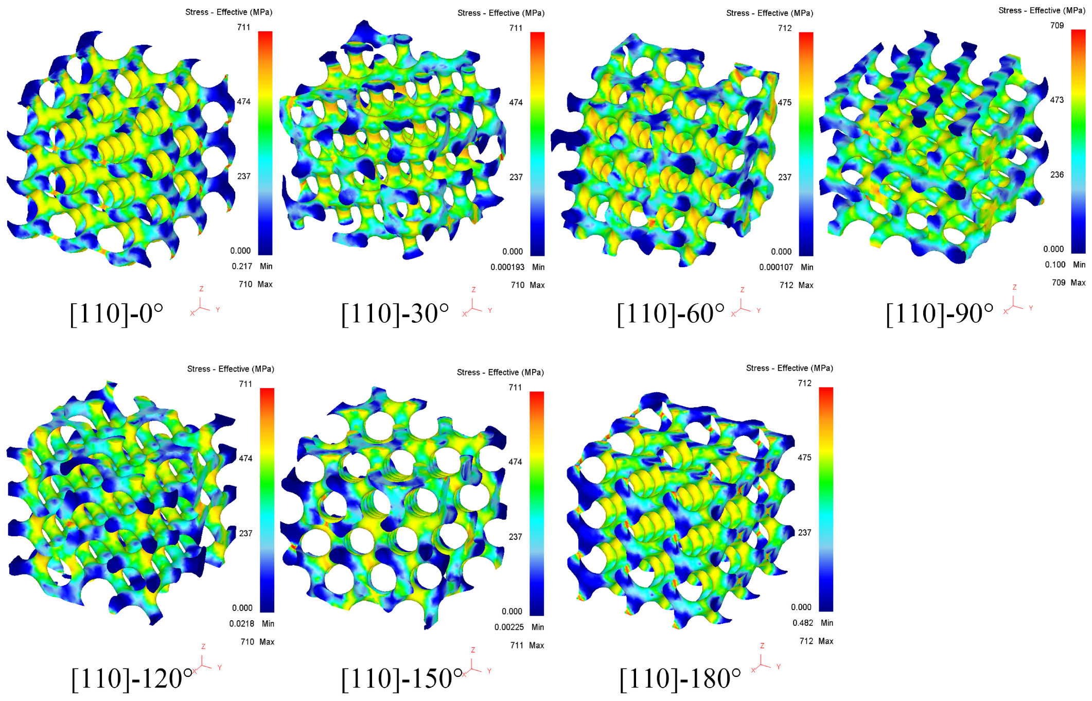
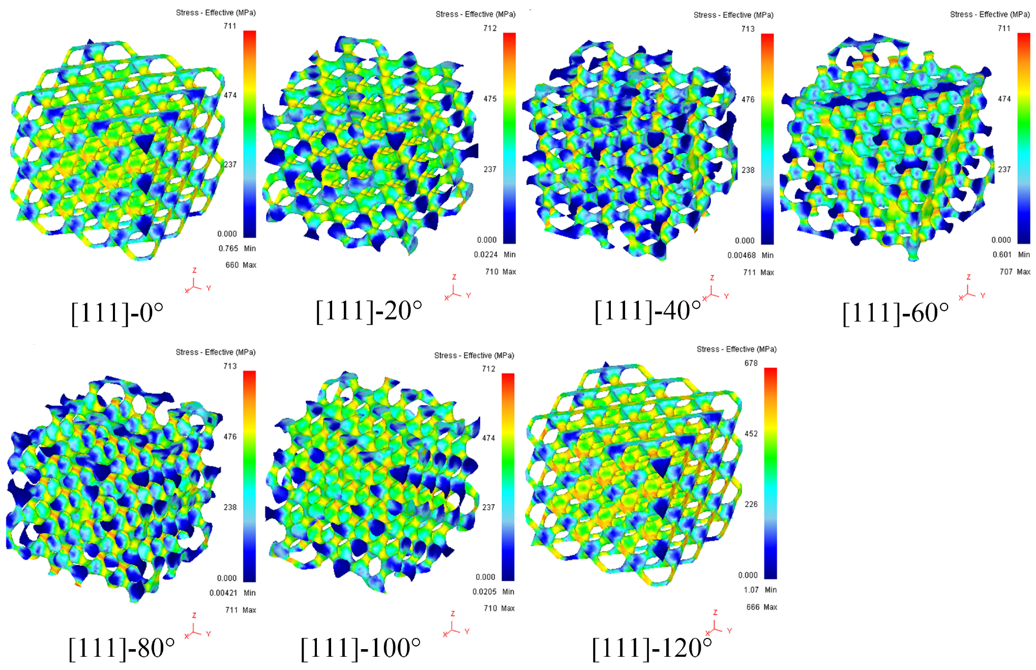
2.3. Finite Element Analysis

The TPMS models were analyzed by Deform software. The unit size was set as 3 mm × 3 mm × 3 mm (L × W × H), and the element number was set as 3 × 3 × 3 (L × W × H). The minimum element size was 0.2 mm in meshing, and the element type was tetrahedron. The bottom plate and top plate were set as rigid. An elastic-plastic model was assigned to the TPMS structure, and the material’s properties were set as follows: elastic modulus of 187 GPa, Poisson’s ratio of 0.3, and yield strength of 458 MPa. The strain–stress data after the yielding stage are listed in Table 2.
The relative elastic modulus can be expressed as follows:
E = E p o r o u s E s o l i d
  • E*: relative elastic modulus of the porous structure.
  • Eporous: elastic modulus of the porous structure.
  • Esolid: elastic modulus of solid materials part.

2.4. Selective Laser Melting

The TPMS was produced by SLM technology (Dimetal-100H, produced by Laseradd Co., Ltd., Guangzhou, China). The processing parameters for SLM are shown in Table 3. The 316L stainless steel powder was supplied by Avimetal Powder Metallurgy Technology Co., Ltd., Beijing, China, and its particle size distribution is 15~53 μm (D10 = 18.5 μm, D50 = 34.5 μm, D90 = 52.7 μm). The chemical composition of 316L powder is shown in Table 4.

2.5. Mechanical Test

The compression test was carried out by a universal testing machine (CMT5105-100kN, SUST Co., Ltd., Zhuhai, China). Compressive speed was controlled at 1 mm/min, and the strain–stress curves of TPMS were obtained by this testing machine. The compression test and data analysis complied with the standard ISO13314:2011 [29].

3. Results and Discussion

3.1. Anisotropy of the Gyroid Structure

Pole diagrams of the relative elastic modulus of the gyroid and its rotation angle are shown in Figure 1.
The relative elastic modulus of the gyroid structure increases and then decreases as the rotation angle increases around the [100] axis. The relative elastic modulus reaches a maximum elastic modulus at 45°, as shown in Figure 1a. The elastic modulus of the gyroid with [100]-45° is 35% higher than that of the initial gyroid structure. After a 90° rotation, the relative elastic modulus of the gyroid with [100]-90° is close to that of the initial structure gyroid-[100]-0°, which verifies that the mechanical properties of the gyroid have 2 π 4 symmetry in the [100] direction. The polar diagrams of the relative elastic modulus of the gyroid are also described in [14], and the changing regulation of the gyroid in [100] is similar to that in our research. There is a direction in which the maximum elastic modulus exists, which is located at 45 degrees. The anisotropy of the gyroid also was illustrated as a color three-dimension map calculated by a Cauchy stiffness tensor [30], showing that the gyroid has high-intensity features on the eight vertices of the diagonal, corresponding to gyroid-[100]-45°.
The change in the relative elastic modulus of the gyroid structure as it rotates around [111] is shown in Figure 1b. As the rotation angle increases, the relative elastic modulus increases and then decreases, and the highest elastic modulus is at 60°. When the rotation angle increases from 0° to 60°, the relative elastic modulus of the gyroid increases from 0.00557 to 0.00831. The relative elastic modulus of gyroid-[111]-60° increases by 49.19% compared to the initial gyroid model. As the rotation angle increases from 60° to 120°, the relative elastic modulus of gyroid-[111]-120° is the same as the relative elastic modulus of gyroid-[100]-0°, indicating that the performance of the structure is consistent with that of the initial gyroid structure after 120° rotation around the [111] direction. Image analysis of the rotating 3D model also shows that the gyroid structure coincides with the initial structure after a rotation of 120°, which verifies that the elastic modulus of the gyroid structure has 2 π 3 symmetry in the [111] direction. The curve of mechanical properties of the polar graph is close to the axis of 60° symmetry, forming a symmetrical distribution.
Figure 1c shows the change in the relative elastic modulus of the gyroid structure after rotating at different angles around the [110] direction. The relative elastic modulus of the gyroid structure increases from 0.00557 to 0.01032 after rotating by 60° in the [110] direction. The relative elastic modulus of the gyroid-[110]-60° is 85.28% higher than that of the gyroid-[100]-0°, indicating that the anisotropy of rotation around the [110] crystal direction is significant. When the gyroid structure rotates 90° around the [110] direction, its relative elastic modulus decreases by 37.11% compared with that of the gyroid-[110]-60°. When gyroid rotates from 90° to 120° around the [110] direction, the relative elastic modulus of gyroid-[110]-120° is equal to the relative elastic modulus of gyroid-[110]-60°. Combined with the gyroid, which rotates from 0° to 180° in the [110] direction, the pole map shows symmetry with the 90° coordinate on the coordinate axis. Figure 2 shows the Von Mises stress cloud of the gyroid rotating at different angles around [110]. When the gyroid rotates to 60° around [110], the z-axis compression performance improves as the angle between the main load struts and the z-axis decreases, and the relative elastic modulus reaches its maximum value.

3.2. Anisotropy of the Diamond Structure

Pole diagrams of the relative elastic modulus of the diamond structure rotating around [100], [111], and [110] are shown in Figure 3. With an increase in the rotation angle around [100], the relative elastic modulus decreases to the minimum value of 0.00818 after rotating by 15°. Then, the relative elastic modulus begins to rise and reaches its maximum value of 0.012 after rotating 45°, as shown in Figure 3a. After 90° rotation, the relative elastic modulus is consistent with the initial relative elastic modulus. This result shows that the relative elastic modulus of the diamond structure is symmetric in the range of 0° to 90° along the 45° axis.
Figure 3b shows the relation between the relative elastic modulus E* of the diamond structure rotating around the axis [111] and the rotation angle, and the stress cloud is shown in Figure 4. The elastic modulus of the diamond structure rotates around the [111] axis, which increases first and then decreases, reaching its maximum value of 0.01609 at 60°, which is 87.09% higher than that of the initial diamond structure. The elastic modulus of the diamond structure is the same as the initial value of the elastic modulus after 120° of rotation around the [111] axis. This result indicates that the anisotropy of the diamond structure rotating around the [111] direction is significant and that the optimal unidirectional compression performance of the diamond structure can be obtained by using an appropriate angle rotation of 60°. This result demonstrates that the mechanical properties of the diamond structure have a symmetric distribution with 60° as the axis of symmetry. Comparing Figure 1b and Figure 3b shows that the change trends of the relative elastic modulus of the gyroid with rotation around the [111] direction are similar to the diamond structure. The relative elastic modulus first rises and then falls, and both structures reach their maximum values after rotating 60° around [111]. Combined with an analysis of crystal symmetry, both diamond and gyroid structures have 2 π 3 symmetry in the [111] direction, so their mechanical properties change similarly.
When the diamond structure rotates around [110] (Figure 3c), its relative elastic modulus first increases and then decreases; the minimum value is 0.01187 after rotating to 90°, and the maximum value is 0.01384 when rotating to 60°. The maximum value is increased by 60.93% compared to the initial value. After the diamond structure rotates 180° around [110], its relative elastic modulus is consistent with that of the initial structure, which verifies the 2 π 2 symmetry of the diamond structure rotated in the [110] direction.

3.3. Anisotropy of the Primitive Structure

The relative elastic modulus of the primitive structure rotating around [100], [111], and [110] is shown in Figure 5. As shown in Figure 5a, when the primitive structure rotates from 0° to 45° around [100], its relative elastic modulus decreases rapidly from 0.0109 to 0.0033. Compared to the modulus of the initial primitive, the relative elastic modulus decreases by 69.75%. When the rotation angle continues to increase, the relative elastic modulus also gradually increases. After a 90° rotation, the relative elastic modulus of primitive-[100]-90° is the same as that of the initial structure primitive-[100]-0°. This result verifies that primitive has 2 π 4 symmetry in the [100] direction. In primitive-[100]-0° and primitive-[100]-90°, the angle between the main bearing struts direction and the pressure loading direction is 0°. When the primitive structure rotates 45° around [100], the struts orientation of the main bearing force of the model is 45° to the direction of pressure loading, and the bearing performance is the lowest. The polar curve of elastic modulus is symmetrical with 45° as its axis, showing a symmetrical distribution of mechanical properties.
The relative elastic modulus of the primitive structure after rotating around the [111] at different angles is shown in Figure 5b. When the rotation angle of the primitive structure increases from 0° to 60°, the relative elastic modulus of the primitive structure gradually decreases and reaches its minimum value at 60°, decreasing from 0.0109 to 0.00298. The relative elastic modulus of primitive-[111]-60° decreases by 72.66% compared to the relative elastic modulus of primitive-[111]-0°. When the rotation angle continues to increase, the relative elastic modulus gradually increases from its minimum value. After rotating at 120°, the relative elastic modulus increases to a maximum value of 0.0109, which is consistent with the relative elastic modulus of primitive-[111]-0°. According to the above analysis, the anisotropy of the primitive structure is significant after rotation around [111] with symmetry of 2 π 3 . Additionally, the anisotropy of the primitive structure around the [100] and [111] crystals is opposite to that of the diamond structure. The primitive structure obtains its minimum value after rotating 45° and 60° around [100] and [111], respectively. The diamond structure achieves its maximum value after rotating 45° and 60° around [100] and [111], respectively. Compared to [100] and [110], the primitive-sheet in the [111] direction presented a higher Young’s modulus [31], which is different from the primitive-struts in our research. This difference may be caused by sheet-based and strut-based structures.
The relative elastic modulus changes of the primitive structure after rotation at different angles around [110] are shown in Figure 5c. When the primitive structure rotates 60° and 120° around [110], the relative elastic modulus decreases from 0.0109 to 0.00244. Compared to the initial primitive structure, the relative elastic modulus of primitive-[110]-60° and primitive-[110]-120° decreases by 77.6%. According to the overall changes in the curves, the polar map presents an axisymmetric distribution with a vertical axis of symmetry. After rotating 180°, the relative elastic modulus of primitive-[110]-180°is consistent with the relative elastic modulus of primitive-[110]-0°. The above analysis shows that the anisotropy of the primitive structure rotating around the [110] crystal is very obvious. Combined with the analysis of the stress cloud in Figure 6, when the strain is 5%, the stress value of struts parallel to the stress direction of primitive-[110]-0° and primitive-[110]-180° is greater than the yield value. These positions represent the maximum stress in the whole stress cloud map. This result shows that the struts in porous structures have the best bearing performance when they are parallel to the force direction in the initial direction.

3.4. Anisotropy of the IWP Structure

The polar diagram of the relative elastic modulus of the IWP structure rotating around [100], [111], and [110] is shown in Figure 7. When the rotation angle increases, its relative elastic modulus increases first and then decreases. The relative elastic modulus reaches its maximum value after 45° rotation, as shown in Figure 7a. The relative elastic modulus of IWP-[100]-45° is 181.4% higher than that of IWP-[100]-0° and shows significant anisotropy. This result indicates that the mechanical properties of the initial structure of IWP can be improved along the [001] direction by rotating around the [100] axis. After the IWP structure is rotated 90° around [100], the relative elastic modulus of the structure is consistent with the initial relative elastic modulus of IWP. The relative elastic modulus of primary IWP-85% is 0.003 [32], and the relative elastic modulus of IWP-85% in our research is 0.006. The reason for this difference is that the IWP structure studied in this article is an optimized structure based on the modified Function (6).
In Figure 7b, after the IWP structure rotates 120° around the [111] direction, the relative elastic modulus of the IWP-[111]-120° and IWP-[111]-0° structures is consistent. This result verifies the 2 π 3 rotational symmetry of the IWP structure around the [111]. After the IWP structure rotates from 0° to 60° around the [111], the relative elastic modulus of IWP-[111]-60° increases by 180.56% compared to the initial structure of IWP. This improvement in mechanical properties is similar to IWP-[100]-45°.
Figure 7c presents a polar diagram of the relative elastic modulus variation of the IWP structure at different angles of rotation around [110]. Compared to Figure 1c and Figure 7c, the relative elastic modulus of the IWP structure changes at different angles around [110], which is similar to the gyroid structure. As the rotation angle increases from 0° to 60°, the relative elastic modulus also increases gradually. The maximum value is 0.02297 after rotation at 60°, which is 275.33% higher than the relative elastic modulus of the initial IWP structure (E* = 0.00612). This polar diagram uses the vertical axis as the axis of symmetry, with a rotation angle of 90°.
According to the stress analysis, as shown in Figure 8, the angle between the main bearing struts of IWP-[110]-60° and the stress direction is 3.8°, while the angle between the main bearing struts of IWP-[110]-0° and the stress direction is 45°. The results indicated that the smaller the off-axis angle, the higher the mechanical properties. After the IWP structure is rotated 180° around the [110] crystallographic direction, both the model and the relative elastic modulus are consistent with those of the initial model and the relative elastic modulus values of the IWP. This result shows that the performance of the IWP structure rotated around the [110] is significantly anisotropic, and it also shows that the IWP structure has 2 π 2 symmetry in the [110] rotation.

3.5. Gradient Rotation Structure

3.5.1. Design and Manufacturing of the Gradient Rotation Structure

According to the anisotropy of the relative elastic modulus of the primitive rotating around [111] crystal orientation, the gradient rotation primitive (GR-primitive) structure was designed. The structure is rotated around [111] crystal orientation by 0° (bottom layer), 20° (middle layer), and 40° (top layer), and then the rotated structures are combined. The porous layers are connected by a 1 mm thick plate. At the same time, an IWP structure with gradient rotation (GR-IWP) was designed. According to the anisotropy of IWP rotation around the [110] crystal direction, the structure is rotated 0° (top layer), 30° (middle layer), and 60° (bottom layer) around the [110] crystal orientation. The arrangement of GR-IWP is similar to that of GR-primitive. These gradient rotation structures were manufactured by SLM technology. The processing parameters are shown in Table 3, and the manufacturing results are shown in Figure 9. This rotation structure distribution is similar to the hierarchical structure of Arapaima gigas scales [33], which can enhance the scale’s ductility and toughness to prevent fracture.

3.5.2. Compressive Properties of the Gradient Rotation Structure

The compressive curves and energy absorption curves of the gradient rotation structures are shown in Figure 10, and the mechanical properties are shown in Table 5. The compression curve of the GR-primitive structure shows three obvious stress peaks. The first stress peak is 30.48 ± 1.40 MPa, the second stress peak is 39.93 ± 2.53 MPa, and the third stress peak is 47.37 ± 1.77 MPa. These three peaks indicate a progressively increasing relationship. Each peak value of GR-primitive corresponds to the compressive fracture strength of each layer of a porous structure. The mechanical properties of the primitive-[111]-40° structure are the weakest among the three layers of the rotating structure, so the first peak value of compressive stress corresponds to the compressive strength of the primitive-[111]-40° structure. The strongest structure is primitive-[111]-0°, corresponding to the third compressive stress peak of 47.37 ± 1.77 MPa, which is 55.4% higher than the first stress peak.
There is only one obvious stress peak (33.79 ± 2.76 MPa) in the compressive curve of the GR-IWP structure, as shown in Figure 10b. After this stress peak, the compressive curve drops significantly, indicating that a fracture occurs in the struts. However, the compression curve of the general IWP structure only has a long yield platform [34], and no fracture occurs. Therefore, structural rotation changes the compression failure mode of IWP. The stress–strain curves of GR-IWP show a step-by-step mode, which is a common mode in graded porous structures, including graded lattice structures [35], graded TPMS porous structures [36], and multi-material porous structures [37]. The appearance of the rising feature of the step is related to the mechanical properties of the IWP rotating structure of each layer. Combined with the anisotropic analysis of IWP rotation around the [110] crystals, the mechanical properties of IWP gradually increase with an increase in the rotation angle, thus showing the step-rise feature in the GR-IWP compression curve. The effective energy absorption of the GR-primitive structure is 12.85 ± 0.58 MJ/m3, which is 25.6% higher than that of the GR-IWP. The energy absorption of G-IWP-A and G-primitive-B with 85% porosity is 6.08 ± 0.19 MJ/m3 and 10.69 ± 0.78 MJ/m3 [27], respectively. These values are lower than the effective energy absorption of GR-IWP and GR-primitive. This comparison shows that the design of gradient rotation is superior to the design of gradient porosity in terms of energy absorption.
The elastic modulus of the GR-primitive structure is 1655.07 ± 93.16 MPa, which is between the elastic modulus of primitive-[111]-0° and primitive-[111]-20°. The elastic modulus of GR-IWP is 1285.41 ± 68.48 MPa, which is between the elastic modulus of IWP-[110]-0° and that of IWP-[110]-30°. The yield strength and effective energy absorption of GR-primitive were both larger than those of GR-IWP. This result demonstrates that properly designing the gradient rotation structure can change the internal mechanical property distribution of the structure. According to the simulation analysis of the primitive rotation around [111], the internal mechanical property distribution of the gradient rotation structure can be preliminarily predicted as follows. The relative elastic modulus of the GR-primitive structure is 2039.55 MPa, 1190.81 MPa, and 635.13 MPa from the lower layer to the upper layer. The GR-primitive structure forms a variable elastic modulus structure. Local positions with a lower elastic modulus give priority to yield deformation and absorb part of the energy. With a gradual increase in strain, the energy absorption value also increases gradually, as shown in Figure 10c. The gradient elastic modulus of the structure can slow the stress changes at both ends of the structure and show multiple stress peaks, which can protect the bottom inner structure.

4. Conclusions

In this study, rotational models of TPMS around [100], [110], and [111] were designed, and the mechanical anisotropic behaviors of the four types of TPMS were analyzed by finite element simulation. Based on the anisotropy of TPMS, gradient rotation structures were designed and studied. The main conclusions are as follows:
(1)
The FEA simulation verified the crystallographic symmetry relationship of the gyroid, diamond, primitive, and IWP structures, which correspond to I4132, F 4 ¯ 3m, P 4 m 3 ¯ 2 m , and I 4 m 3 ¯ 2 m , respectively. In particular, the anisotropy of the gyroid and diamond structures rotating around the [111] direction was found to be significant, with the highest relative elastic modulus obtained by rotating the structure 60°.
(2)
The unidirectional compression performance of TPMS can be greatly improved through rotation around a specific orientation. However, it should be noted that due to the significant anisotropy, the performance of TPMS will significantly decrease in specific directions. Therefore, when designing structures under complex working conditions, it is necessary to reasonably consider the bearing capacity in the fragile direction.
(3)
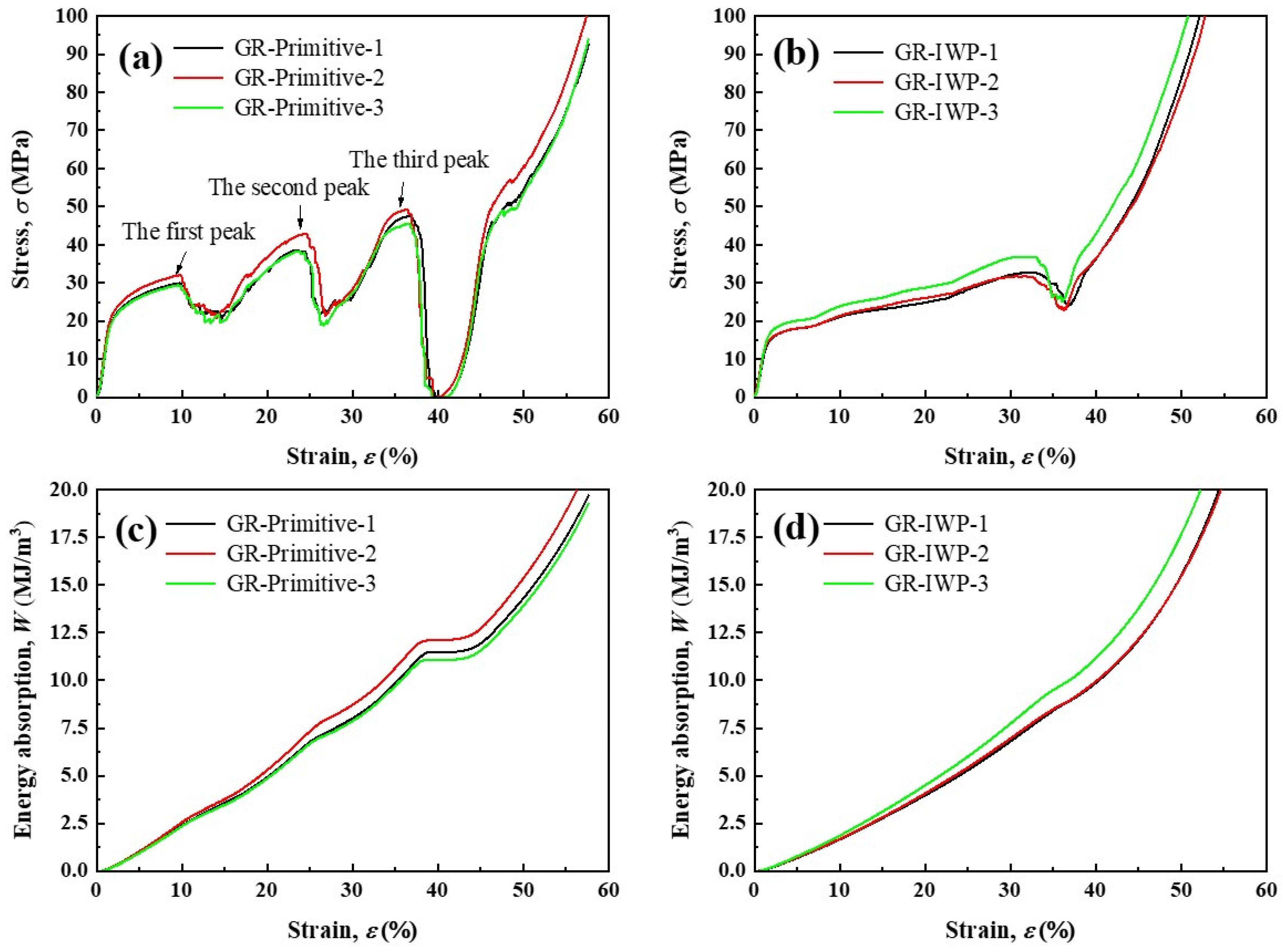
A gradient rotation structure was designed based on the anisotropic properties of TPMS. The compressive behavior of the gradient rotation structure was related to the rotation angle of struts and showed a step-by-step mode in GR-IWP and multi-peaks in GR-primitive. The design of the gradient rotation structure enhanced the energy absorption properties of TPMS.

Author Contributions

Conceptualization, M.Z.; methodology, M.Z.; formal analysis, J.L., C.L. and M.D.; investigation, M.Z. and J.L.; data curation, M.Z., J.L. and X.L.; writing—original draft preparation, M.Z.; writing—review and editing, J.L., M.D., X.L. and D.W.; visualization, C.L.; supervision, D.W.; project administration, M.Z.; funding acquisition, M.Z. All authors have read and agreed to the published version of the manuscript.

Funding

This research was funded by the Guangdong Basic and Applied Basic Research Foundation-Youth Fund Project (no. 2021A1515110033), Guangdong Natural Science Foundation (no. 2023A1515012704), and Zhanjiang Ocean Youth Talent Innovation Project (no. 2021E05001), Program for Scientific Research Start-up Funds of Guangdong Ocean University (no. 360302022201).

Institutional Review Board Statement

Not applicable.

Informed Consent Statement

Not applicable.

Data Availability Statement

Data sharing is not applicable to this article.

Conflicts of Interest

The authors declare no conflict of interest.

References

  1. Shitole, P.; Gupta, A.; Ghosh, R. Fracture Mechanism and Fracture Toughness at the Interface Between Cortical and Cancellous Bone. J. Biomech. Eng. 2019, 141, 114502. [Google Scholar] [CrossRef]
  2. Habibi, M.K.; Samaei, A.T.; Gheshlaghi, B.; Lu, J.; Lu, Y. Asymmetric flexural behavior from bamboo’s functionally graded hierarchical structure: Underlying mechanisms. Acta Biomater. 2015, 16, 178–186. [Google Scholar] [CrossRef] [PubMed]
  3. Drol, C.J.; Kennedy, E.B.; Hsiung, B.K.; Swift, N.B.; Tan, K.T. Bioinspirational understanding of flexural performance in hedgehog spines. Acta Biomater. 2019, 94, 553–564. [Google Scholar] [CrossRef] [PubMed]
  4. Taylor Parkins, S.K.; Murthy, S.; Picioreanu, C.; Kuhl, M. Multiphysics modelling of photon, mass and heat transfer in coral microenvironments. J. R. Soc. Interface 2021, 18, 20210532. [Google Scholar] [CrossRef] [PubMed]
  5. Liu, Z.; Meyers, M.A.; Zhang, Z.; Ritchie, R.O. Functional gradients and heterogeneities in biological materials: Design principles, functions, and bioinspired applications. Prog. Mater. Sci. 2017, 88, 467–498. [Google Scholar] [CrossRef]
  6. Zheng, X.; Fu, Z.; Du, K.; Wang, C.; Yi, Y. Minimal surface designs for porous materials: From microstructures to mechanical properties. J. Mater. Sci. 2018, 53, 10194–10208. [Google Scholar] [CrossRef]
  7. Szatkiewicz, T.; Laskowska, D.; Balasz, B.; Mitura, K. The Influence of the Structure Parameters on the Mechanical Properties of Cylindrically Mapped Gyroid TPMS Fabricated by Selective Laser Melting with 316L Stainless Steel Powder. Materials 2022, 15, 4352. [Google Scholar] [CrossRef]
  8. Ge, J.; Huang, J.; Lei, Y.; O’Reilly, P.; Ahmed, M.; Zhang, C.; Yan, X.; Yin, S. Microstructural features and compressive properties of SLM Ti6Al4V lattice structures. Surf. Coat. Technol. 2020, 403, 126419. [Google Scholar] [CrossRef]
  9. Guo, X.; Ding, J.; Li, X.; Qu, S.; Song, X.; Fuh, J.Y.H.; Lu, W.F.; Zhai, W. Enhancement in the mechanical behaviour of a Schwarz Primitive periodic minimal surface lattice structure design. Int. J. Mech. Sci. 2022, 216, 106977. [Google Scholar] [CrossRef]
  10. Fan, X.; Tang, Q.; Feng, Q.; Ma, S.; Song, J.; Jin, M.; Guo, F.; Jin, P. Design, mechanical properties and energy absorption capability of graded-thickness triply periodic minimal surface structures fabricated by selective laser melting. Int. J. Mech. Sci. 2021, 204, 106586. [Google Scholar] [CrossRef]
  11. Zhang, M.; Li, J.; Liao, X.; Xu, M.; Shi, W. Influence of cycle number on the compression behavior of nonlinear periodically gradient porous structures produced by laser powder bed fusion. Mater. Des. 2022, 223, 111257. [Google Scholar] [CrossRef]
  12. Weißmann, V.; Bader, R.; Hansmann, H.; Laufer, N. Influence of the structural orientation on the mechanical properties of selective laser melted Ti6Al4V open-porous scaffolds. Mater. Des. 2016, 95, 188–197. [Google Scholar] [CrossRef]
  13. Choy, S.Y.; Sun, C.-N.; Leong, K.F.; Wei, J. Compressive properties of Ti-6Al-4V lattice structures fabricated by selective laser melting: Design, orientation and density. Addit. Manuf. 2017, 16, 213–224. [Google Scholar] [CrossRef]
  14. Yang, L.; Yan, C.; Fan, H.; Li, Z.; Cai, C.; Chen, P.; Shi, Y.; Yang, S. Investigation on the orientation dependence of elastic response in Gyroid cellular structures. J. Mech. Behav. Biomed. Mater. 2019, 90, 73–85. [Google Scholar] [CrossRef] [PubMed]
  15. Barber, H.; Kelly, C.N.; Nelson, K.; Gall, K. Compressive anisotropy of sheet and strut based porous Ti-6Al-4V scaffolds. J. Mech. Behav. Biomed. Mater. 2021, 115, 104243. [Google Scholar] [CrossRef]
  16. Peng, X.; Huang, Q.; Zhang, Y.; Zhang, X.; Shen, T.; Shu, H.; Jin, Z. Elastic response of anisotropic Gyroid cellular structures under compression: Parametric analysis. Mater. Des. 2021, 205, 109706. [Google Scholar] [CrossRef]
  17. Krishnan, K.; Lee, D.-W.; Al Teneji, M.; Abu Al-Rub, R.K. Effective stiffness, strength, buckling and anisotropy of foams based on nine unique triple periodic minimal surfaces. Int. J. Solids Struct. 2022, 238, 111418. [Google Scholar] [CrossRef]
  18. Lu, Y.; Zhao, W.; Cui, Z.; Zhu, H.; Wu, C. The anisotropic elastic behavior of the widely-used triply-periodic minimal surface based scaffolds. J. Mech. Behav. Biomed. Mater. 2019, 99, 56–65. [Google Scholar] [CrossRef]
  19. Kapfer, S.C.; Hyde, S.T.; Mecke, K.; Arns, C.H.; Schroder-Turk, G.E. Minimal surface scaffold designs for tissue engineering. Biomaterials 2011, 32, 6875–6882. [Google Scholar] [CrossRef]
  20. Zhang, L.; Ma, Q.; Ding, J.; Qu, S.; Fu, J.; Fu, M.W.; Song, X.; Wang, M.Y. Design of elastically isotropic shell lattices from anisotropic constitutive materials for additive manufacturing. Addit. Manuf. 2022, 59, 103185. [Google Scholar] [CrossRef]
  21. Liu, Z.; Zhang, Z.; Ritchie, R.O. Structural Orientation and Anisotropy in Biological Materials: Functional Designs and Mechanics. Adv. Funct. Mater. 2020, 30, 1908121. [Google Scholar] [CrossRef]
  22. Yang, R.; Zaheri, A.; Gao, W.; Hayashi, C.; Espinosa, H.D. AFM Identification of Beetle Exocuticle: Bouligand Structure and Nanofiber Anisotropic Elastic Properties. Adv. Funct. Mater. 2016, 27, 1603993. [Google Scholar] [CrossRef]
  23. Yang, W.; Chen, I.H.; Gludovatz, B.; Zimmermann, E.A.; Ritchie, R.O.; Meyers, M.A. Natural flexible dermal armor. Adv. Mater. 2013, 25, 31–48. [Google Scholar] [CrossRef]
  24. Bruet, B.J.F.; Song, J.; Boyce, M.C.; Ortiz, C. Materials design principles of ancient fish armour. Nat. Mater. 2008, 7, 748–756. [Google Scholar] [CrossRef] [PubMed]
  25. Amini, S.; Masic, A.; Bertinetti, L.; Teguh, J.S.; Herrin, J.S.; Zhu, X.; Su, H.; Miserez, A. Textured fluorapatite bonded to calcium sulphate strengthen stomatopod raptorial appendages. Nat. Commun. 2014, 5, 3187. [Google Scholar] [CrossRef] [PubMed] [Green Version]
  26. Li, D.; Liao, W.; Dai, N.; Dong, G.; Tang, Y.; Xie, Y.M. Optimal design and modeling of gyroid-based functionally graded cellular structures for additive manufacturing. Comput.-Aided Des. 2018, 104, 87–99. [Google Scholar] [CrossRef]
  27. Zhang, M.; Yang, Y.; Qin, W.; Wu, S.; Chen, J.; Song, C. Optimizing the pinch-off problem for gradient triply periodic minimal surface cellular structures manufactured by selective laser melting. Rapid Prototyp. J. 2020, 26, 1771–1781. [Google Scholar] [CrossRef]
  28. Schoen, A.H. Infinite Periodic Minimal Surfaces without Self-Intersections; National Aeronautics and Space Administration: Washington, DC, USA, 1970. [Google Scholar]
  29. ISO 13314:2011; Mechanical Testing of Metals—Ductility Testing—Compression Test for Porous and Cellular Metals. ISO: Geneva, Switzerland, 2011.
  30. Jones, A.; Leary, M.; Bateman, S.; Easton, M. Parametric design and evaluation of TPMS-like cellular solids. Mater. Des. 2022, 221, 110908. [Google Scholar] [CrossRef]
  31. Fu, J.; Ding, J.; Qu, S.; Zhang, L.; Wang, M.Y.; Fu, M.W.; Song, X. Improved light-weighting potential of SS316L triply periodic minimal surface shell lattices by micro laser powder bed fusion. Mater. Des. 2022, 222, 110803. [Google Scholar] [CrossRef]
  32. Al-Ketan, O.; Abu Al-Rub, R.K.; Rowshan, R. The effect of architecture on the mechanical properties of cellular structures based on the IWP minimal surface. J. Mater. Res. 2018, 33, 343–359. [Google Scholar] [CrossRef]
  33. Zimmermann, E.A.; Gludovatz, B.; Schaible, E.; Dave, N.K.; Yang, W.; Meyers, M.A.; Ritchie, R.O. Mechanical adaptability of the Bouligand-type structure in natural dermal armour. Nat. Commun. 2013, 4, 2634. [Google Scholar] [CrossRef] [PubMed] [Green Version]
  34. Zhang, M.; Xu, M.; Li, J.; Shi, W.; Chen, Y. Compressive behavior of hollow triply periodic minimal surface cellular structures manufactured by selective laser melting. Rapid. Prototyp. J. 2022, 29, 569–581. [Google Scholar] [CrossRef]
  35. Maskery, I.; Aboulkhair, N.; Aremu, A.; Tuck, C.; Ashcroft, I.; Wildman, R.D.; Hague, R. A mechanical property evaluation of graded density Al-Si10-Mg lattice structures manufactured by selective laser melting. Mater. Sci. Eng. A 2016, 670, 264–274. [Google Scholar] [CrossRef] [Green Version]
  36. Yang, L.; Mertens, R.; Ferrucci, M.; Yan, C.; Shi, Y.; Yang, S. Continuous graded Gyroid cellular structures fabricated by selective laser melting: Design, manufacturing and mechanical properties. Mater. Des. 2019, 162, 394–404. [Google Scholar] [CrossRef]
  37. Zhang, M.; Yang, Y.; Xu, M.; Chen, J.; Wang, D. Mechanical properties of multi-materials porous structures based on triply periodic minimal surface fabricated by additive manufacturing. Rapid Prototyp. J. 2021, 27, 1681–1692. [Google Scholar] [CrossRef]
Figure 1. The polar diagram of relative elastic modulus of gyroid: (a) rotation around [100], (b) rotation around [111], and (c) rotation around [110].
Coatings 13 01206 g001
Figure 2. Stress cloud map of gyroid rotating around [110] (strain = 5%).
Coatings 13 01206 g002
Figure 3. The polar diagram of relative elastic modulus of diamond: (a) rotation around [100], (b) rotation around [111], and (c) rotation around [110].
Coatings 13 01206 g003
Figure 4. Stress cloud of diamond rotating around [111] (strain = 5%).
Coatings 13 01206 g004
Figure 5. The polar diagram of the relative elastic modulus of primitive: (a) rotation around [100], (b) rotation around [111], and (c) rotation around [110].
Coatings 13 01206 g005
Figure 6. Stress contour of primitive rotating around [110] (strain = 5%).
Coatings 13 01206 g006
Figure 7. The polar diagram of the relative elastic modulus of IWP: (a) rotation around [100], (b) rotation around [111], and (c) rotation around [110].
Coatings 13 01206 g007
Figure 8. Stress contour of IWP rotating around [110] (strain = 5%).
Coatings 13 01206 g008
Figure 9. TPMS porous structure with gradient rotation.
Coatings 13 01206 g009
Figure 10. Compressive curves of (a) GR-primitive, (b) GR-IWP, and energy absorption curves of (c) GR-primitive, (d) GR-IWP.
Coatings 13 01206 g010
Table 1. Crystallographic symmetry relationship of TPMS.
TPMSBravais LatticeSpace GroupsAxis of Symmetry
GyroidBody-centered cubicI4132 2 π 4 , 2 π 3 , 2 π 2
DiamondFace-centered cubicF 4 ¯ 3m 2 π 4 , 2 π 3 , 2 π 2
PrimitiveSimple cubicP 4 m 3 ¯ 2 m 2 π 4 , 2 π 3 , 2 π 2
IWPBody-centered cubicI 4 m 3 ¯ 2 m 2 π 4 , 2 π 3 , 2 π 2
Table 2. Strain–stress data after yielding stage.
Strain after Yielding00.003540.011940.020420.031740.045040.061140.084640.10210.12454
Stress/MPa458.00475.27489.32507.76530.00552.24574.77611.36635.35668.13
Table 3. The processing parameter for SLM.
Laser Power
(W)
Scanning Speed
(mm/s)
Layer Thickness
(mm)
Scanning Space
(mm)
1808000.030.07
Table 4. Chemical composition of 316L powder.
ElementFeCrNiMoMnSiPCSO
Composition (wt.%)Bal.17.1110.632.420.880.530.010.0090.0030.049
Table 5. Compressive properties of gradient rotation porous structure.
PerformanceGR-PrimitiveGR-IWP
Elasticity modulus1655.07 ± 93.161285.41 ± 68.48
Yield strength19.58 ± 1.0714.27 ± 1.18
The first stress peak30.48 ± 1.4033.79 ± 2.76
The second stress peak39.93 ± 2.53-
The third stress peak47.37 ± 1.77-
Effective energy absorption12.85 ± 0.589.01 ± 0.39
Disclaimer/Publisher’s Note: The statements, opinions and data contained in all publications are solely those of the individual author(s) and contributor(s) and not of MDPI and/or the editor(s). MDPI and/or the editor(s) disclaim responsibility for any injury to people or property resulting from any ideas, methods, instructions or products referred to in the content.

