Article

Double-Glow Plasma Surface Alloying of BTi-62421S Alloys: Regulation of Microstructure Properties

School of Materials Science and Engineering, North University of China, Taiyuan 030051, China
*
Author to whom correspondence should be addressed.
Coatings 2023, 13(5), 933; https://doi.org/10.3390/coatings13050933
Submission received: 17 April 2023 / Revised: 10 May 2023 / Accepted: 12 May 2023 / Published: 16 May 2023

Abstract

:
In order to meet the design requirements of lightweight artillery and adopt the method of double-glow plasma nitriding to solve the problem of low hardness and poor abrasion resistance of Ti alloy, the BTi-62421S high-performance titanium (Ti) alloy was selected as the experimental material to replace gun steel. To study the effect of different nitrogen (N) concentrations on the heat resistance scouring performance of BTi-62421S high-performance Ti alloy and investigate the influence of alloying elements on the heat resistance scouring performance under the same parameters compared with the commonly used TC4 Ti alloy, argon was used as the protective gas by continuously increasing the N concentration (Ar/N2 = 1:1, 1:2, 1:3). It was found that the honeycomb structure on the surface of the sample and the thickness of the coating increased continuously, reaching a thickness of 15 μm, while the depth of the nitride particles extending from the coating to the substrate also increased, reaching a maximum depth of 26 μm. The orientation of TiN changed from 37° to 62°. The hardness of the coating showed a negative correlation with the coefficient of frictional abrasion, which significantly improved the heat-resistant scouring performance of BTi-62421S high-performance Ti alloy.

1. Introduction

Artillery is an important weapon in modern warfare, and lightweight has become the “main battlefield” of military equipment competition between countries. Although the current improvement in material technology has made it lighter, it is far from enough. As one of the three major lightweight materials, Ti alloy has the advantages of low density and high specific strength, and its strength even exceeds that of many alloy structural types of steel. Naturally, it has become the material of first choice to replace gun steel. However, due to the disadvantage of the poor heat-resistant scouring performance, the results of this replacement have been impossible to achieve [1,2,3,4]. The performance of heat-resistant scouring directly affects the service life of the barrel, and it is mainly reflected in the following two aspects. On the one hand, the unburned powder particles in the propellant powder and the metal particles generated by the friction between the projectile and the rifling during the high-speed movement could scour the barrel and make a small amount of micro-cutting. On the other hand, the projectile should possess a certain rotational speed at the time of discharge to ensure the accuracy of shooting. Therefore, the high-speed gas pressure at the bottom of the projectile and the tight wrapping of the spiral rifling during the process of the projectile out of the barrel resulted in the violent friction generated between the projectile and the rifling [5,6]. In order to solve the shortcomings of the poor heat-resistant scouring performance of Ti alloys, surface-alloying technology is applied to improve the surface hardness and wear resistance of the substrate [7,8,9].
At present, there are many pieces of research on surface-alloying technology at home and overseas. The study concerning the friction and wear behavior of Ti following laser surface alloying (LSA) with Si, Al, or Si + Al was analyzed by J. Dutta Majumdar [10]. The said tribological characteristics of the laser-alloyed samples, subjected to the earlier determined optimum conditions of LSA, were investigated in terms of the variation of wear depth. The results showed that hard coatings could improve the wear resistance of Ti alloy surfaces, but the treated surface coating is prone to generate microcracks, which exacerbated the detachment rate of the coating in high-temperature and high-speed particle impact environments. The depth distributions and compounds of Ti6Al4V ion-implanted with carbon (C), N, platinum (Pt), or gold (Au) were investigated by H. Schmidt [11], and the microhardness and the surface damage occurring during wear tests against polyethylene were determined. It could be found that the surface layer hardness and wear resistance of ion implantation had been improved, but the ion implantation layer of this type of technology was relatively shallow (≤0.5 μm). Under high-speed particle impact, the hard coating may deform inconsistently with the substrate, leading to cracking.
The same as the surface alloying technology of the double-glow plasma surface alloying technique, it has the advantages of a dense coating surface, thick coating thickness, surface alloy layer composition can be controlled, etc. Currently, this technology is better studied in TC4 Ti alloy. Double-glow plasma nitriding experiments were conducted on TC4 Ti alloy by Wei Hu [12], and the effect of the flow ratio of argon to N in the atmosphere on the properties was investigated. The results showed that with the increasing concentration of N in the atmosphere, the thickness of the alloy layer increased, and the thickest coating was about 10 μm. At the same time, the surface hardness was significantly improved. Dong-Bo Wei et al. [9] investigated the high-temperature oxidation behavior of double-glow plasma chromizing coating and found that a Ti-Cr interdiffusion layer was formed on the alloy surface after surface alloying. During oxidation, the diffusion of oxygen was prevented by the multilayer oxide film formed by the outward diffusion of Cr, Ti, and Al. However, there have been fewer studies on BTi-62421S Ti alloy in the past, especially on the application of the double-glow plasma surface alloying technique to BTi-62421S Ti alloy. If it is not studied, it cannot meet the design requirements of lightweight artillery.
In this experiment, the double-glow plasma surface alloying technique was applied for the first time to the study of BTi-62421S Ti alloy, a high-temperature Ti alloy, which can maintain a good performance state under a long-term thermal exposure environment and enhance the high-temperature resistance from the substrate. Meanwhile, double-glow plasma nitriding experiments were conducted on the substrate surface to prepare a coating with a dense surface and good bonding performance by adjusting the N concentration and studying the effect of different concentrations on the heat-resistance scouring performance of the coating. Furthermore, the effect of matrix alloying elements on the heat-resistant scouring performance of the coating was also investigated by comparing it with TC4 alloy under the same parameters.

2. Materials and Methods

2.1. Experimental Materials

In this experiment, BTi-62421S and TC4 alloys were used as substrates, which belonged to near-α and (α + β) Ti alloys, respectively. The chemical compositions of the alloys are shown in Table 1 and Table 2. The substrates are plasma sintered by LABOX-210 equipment (Sinter Land INC., Niigata, Japan).

2.2. Specimen Preparation

The casting bar was processed into a specimen of Φ12 mm × 3 mm by wire-electrode cutting, sandpapered from 1000# to 7000#, and then mechanically polished. Ultrasonic cleaning and drying of polished specimens to prepare for subsequent double-glow plasma nitriding.

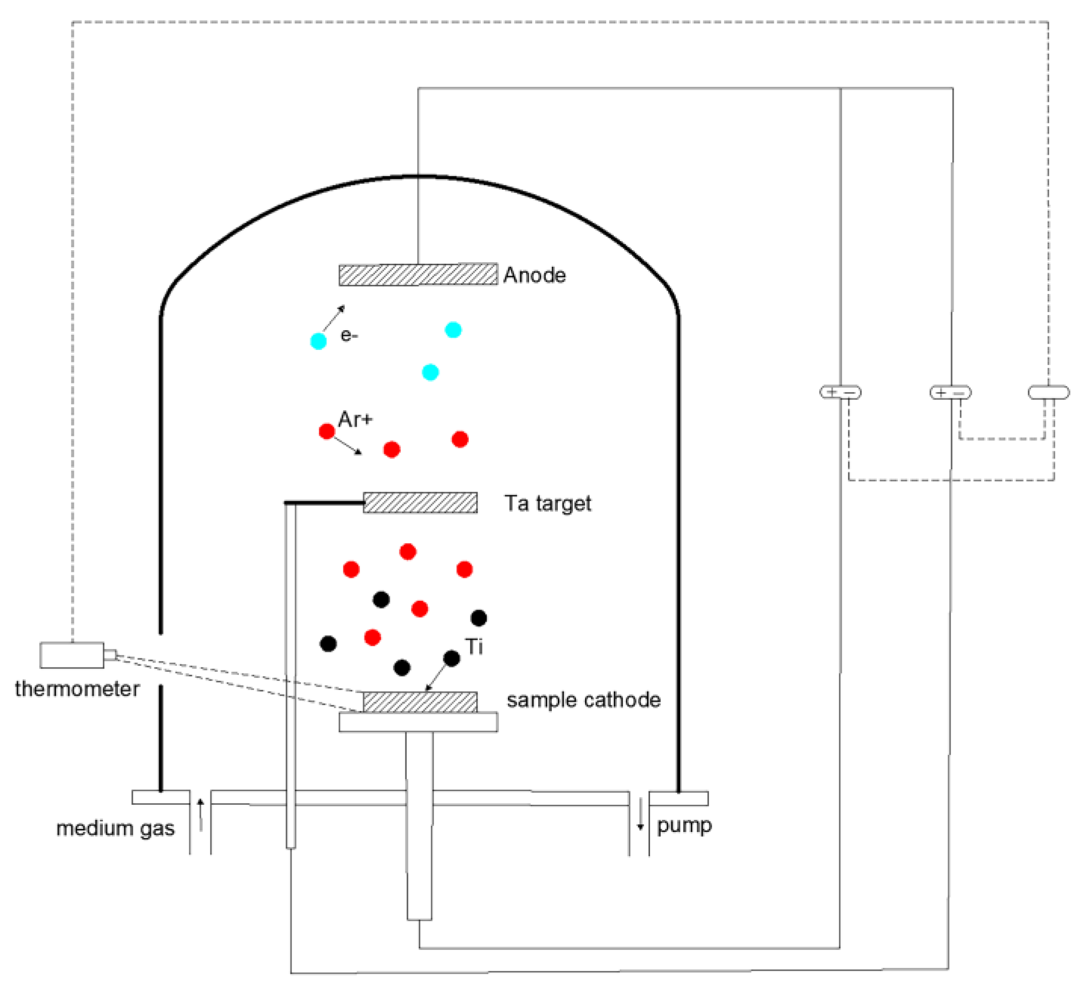
2.3. Experimental Equipment and Parameters

The experiment was conducted on MIP-800C multifunctional double-glow plasma infiltration coating equipment. The equipment schematic diagram is shown in Figure 1, and the experimental parameters are shown in Table 3.
Prepare a piece of source target with the size of Φ100 mm before the double-glow plasma surface coating experiment. The target made of pure Ti metal was polished to 7000# with sandpaper, cleaned and dried with ultrasonic, and then loaded into the MIP-800C multifunctional double-glow plasma infiltration coating equipment.
Place the prepared BTi-62421S and TC4 Ti alloy specimens on the working electrode in Figure 1, and pump the furnace to a vacuum state. Fill the protective gas argon, and turn on the power supply of the workpiece electrode. When the voltage reached 300 V, the work-piece electrode generated a glow discharge. The argon ions bombarded and cleaned the oil stains and oxide film on the surface of the workpiece, facilitating the adsorption of active atoms. The workpiece was heated after ion bombardment. When the workpiece pole voltage reached about 600 V, argon ion bombarded cleaning was finished, and the N gas was injected. The volume flow ratio of Ar/N2 was adjusted to 1:1, 1:2, and 1:3, respectively, to maintain the ultra-low air pressure in the furnace at around 35 Pa. Turn on the source power supply, slowly increase to around 1000 V, and maintain the temperature in the furnace at around 840 °C for 5 h of double-glow plasma surface coating. After the end of the double-glow plasma surface coating, we reduced the source voltage and the sample cathode voltage in sequence, slowly cooled down to room temperature, and removed the specimen [15,16].

2.4. Coating Microstructure and Properties Tests

The specimen needed to undergo cross-section and surface morphology testing, where the cross-section test required wire-electrode cutting along the longitudinal direction. The cross-section was sanded to 10000# with sandpaper and then mechanically polished. The surface microstructure of the specimens and the thickness of the coating were observed by scanning electron microscopy, which was a field emission scanning electron microscope (SEM, Hitachi, Tokyo, Japan) with an acceleration voltage of 20 kV. The phase composition of the coatings was measured by X-ray diffractometer (XRD, Rigaku, Tokyo, Japan) using Cu target rays with a scanning speed of 4°/min and a 2θ range of 10°–90°. The heat-resistant scouring performance of the analyzed coatings is characterized by microhardness and friction abrasion coefficient. The microhardness was measured by HVS-1000 digital display micro-Vickers hardness tester (Walter Uhl techn. Mikroskopie GmbH&Co. KG, Wetzlar Asslar, Germany) with a load of 100 g and a loading time of 15 s. The friction abrasion coefficient of the coating was measured using the MFT-4000 multifunctional material surface property tester (Lanzhou Huahui Instrument Technology Co., Ltd., Lanzhou, China) with a loading load of 40 N, a friction length of 5 mm, a friction frequency of 50 mm/min, and a friction pair with a diameter of 5 mm.

3. Results and Discussion

3.1. Surface Microstructure and Phase Composition

Figure 2 shows the surface microstructure of BTi-62421S and TC4 Ti alloy specimens with different Ar/N2 flow ratios. It can be found that the surface of the specimen is dense, without obvious holes and cracks. The surface of the specimens has many raised structures, which is the typical characteristic of the surface microstructure of the double-glow plasma surface alloying technique. Previous research found that in the process of double-glow plasma nitriding coating, pre-generated argon ions were generated in advance to bombard the N molecules and source electrode targets in the furnace, and reactive active N species and active Ti particles were sputtered out to form active atomic clusters. At the same time, the atoms on the surface of the alloy matrix are also bombarded by argon ions, which obtain energy and detach from the matrix surface, forming a large number of vacancy defects and increasing the adsorption ability of the active atomic clusters. The active atomic clusters are adsorbed onto the low-energy defects of the matrix and rapidly nucleate, accompanied by continuous adsorption of active atomic groups onto the surface of the matrix. The initial crystal nucleus grows and forms a convex structure by the continuous accumulation of active atomic clusters [17,18]. Figure 2a–c shows the surface morphology of BTi-62421S Ti alloy specimens with Ar/N2 flow ratios of 1:1, 1:2, and 1:3, respectively. The fine honeycomb-like raised structure can be observed in the figure [19]. As the N flow rate ratio continues to increase, it can be found that the honeycomb structure on the surface of the specimen is increasing. The fine honeycomb structures in Figure 2a are between 0.5 μm and 1 μm in diameter. Comparing Figure 2b,c, it can be seen that the convex structure on the surface of the specimen is not only increasing but also sputtering more uniformly.
Compared to the honeycomb structure in Figure 2a–c, the microstructure on the surface of TC4 specimens has changed significantly. The uneven island structure of the specimen surface can be observed through SEM [9]. Figure 2f exhibits the surface microstructure of the TC4 Ti alloy specimen with an Ar/N2 flow ratio of 1:3, and this island-like structure is especially evident in the figure. By observation, it can be found that with the continuous increase in the Ar/N2 flow ratio, the honeycomb structure on the surface of the BTi-62421S Ti alloy specimen and the island-like structure on the surface of the TC4 Ti alloy specimen both show a structural increase. The reason for this result may be that as the concentration of N in the equipment continues to increase, the probability of the active particles being splashed out increases, and more active particles promote the growth of honeycomb and island-like structures on the surface of the specimen.
Figure 3 shows the corresponding element diagrams for EDS analysis of the surface coating of BTi-62421S Ti alloy specimens with Ar/N2 flow ratios of 1:1, 1:2, and 1:3. It can be seen from the graph that the coating surface is composed of two elements, Ti and N. The Ti element is represented by blue color, and the N element is represented by green color. Each bright spot represents the part where the corresponding element is concentrated. From the graph, it can be observed that the elements are evenly distributed on the coating surface, and there are no obvious enrichment areas. It can be seen from the graph that the N content in the EDS diagrams increases as the Ar/N2 flow ratio continues to increase. This also confirms previous suspicions that as the N concentration in the equipment continues to rise, the probability of the active particles being sputtered out increases, and more active particles are sputtered onto the surface of the specimen, promoting the growth of honeycomb structures.
Figure 4 shows the EDS diagrams of the surface coating of TC4 Ti alloy specimens with different Ar/N2 flow ratios. It can be found from the figure that with increasing N content, the EDS diagrams of TC4 specimens show the same pattern as that of BTi-62421S Ti alloy specimens, but the content of N elements is less than BTi-62421S Ti alloy specimens.
Figure 5 displays the phase composition of the surface coating of BTi-62421S and TC4 Ti alloy specimens analyzed by XRD. It can be observed in the figure that the phase composition of all six specimens includes TiN and Ti. Wei Hu et al. investigated the double-glow plasma nitriding experiments on Ti6Al4V alloy [12]. The experiment found that due to the thin thickness of the nitriding layer and the thicker penetration depth of X-ray, the detected Ti phase was the Ti phase in the matrix. Figure 5a shows the phase composition of the BTi-62421S alloy specimen. It can be seen from the figure that the phase composition of the XRD pattern with an Ar/N2 flow ratio of 1:1 mainly consists of TiN and Ti2N, with the main diffraction peak located at around 37°. There is an overlap of TiN and Ti2N diffraction peaks that appears at the main diffraction peak. Honghong Zhang et al. [20] found in their study of the damage mechanism of the TiN/Ti multilayers with different modulation periods under the cyclic impact that the overlapping diffraction peaks of TiN and Ti2N exhibited a layered alternating subgrain structure. The appearance of Ti2N was owing to the absence of TiN due to insufficient nitrogen content, and the hardness of Ti2N was significantly lower than that of TiN. The main phase composition of both specimens in the XRD patterns with Ar/N2 flow ratios of 1:2 and 1:3 in Figure 5a is TiN and the main diffraction peaks are both located around 62°. However, compared to the XRD pattern with an Ar/N2 flow ratio of 1:1, the position and intensity of the main diffraction peaks with Ar/N2 flow ratios of 1:2 and 1:3 have changed significantly, and only a single TiN diffraction peak is present, indicating that the microstructure and composition of the coating have undergone significant changes. Figure 5b exhibits the phase composition of the TC4 alloy specimen. It can be seen from the figure that the phase composition of the XRD pattern with an Ar/N2 flow ratio of 1:1 also consists of TiN and Ti2N. However, the position of the main diffraction peak has changed compared to that of the BTi-62421S alloy specimen, and there is no overlap of TiN and Ti2N in the main diffraction peak. The phase composition in the XRD patterns with Ar/N2 flow ratios of 1:2 and 1:3 is also TiN, and the position of the main diffraction peak remains unchanged.

3.2. Coating Thickness

Figure 6 shows the cross-sectional appearance of BTi-62421S Ti alloy specimens with different Ar/N2 flow ratios. It can be seen from the figure that a continuous alloy-modified layer is formed on the surface, which is completely different from the substrate. Figure 6a shows the cross-sectional appearance of the Ar/N2 flow ratio of 1:1, and the thickness of the surface nitride layer is about 7 μm. From the magnified image, it can be observed that there are some needle-like (red arrow) or fine-grained (blue arrow) particles below the surface nitride layer. These microstructures extend from the surface layer to the matrix, providing channels for the continuous diffusion of active atomic clusters into the interior of the matrix [21,22]. Hongyu Yang believed that during the sputtering stage, Ar ions bombard the surface of the Ti6Al4V alloy to form a large number of vacancy defects [23]. When the active atomic clusters adsorb and diffuse on the surface of the specimen, they preferentially gather at the defects on the surface of the specimen. As the defects on the surface of the specimen are occupied, the active atomic clusters begin to diffuse into the interior of the specimen. With the reduction in vacancy defects, lattice distortion, and the generation of the resistance of the active atomic group to diffuse inward gradually increases, affecting the adsorption capacity of the sample surface. However, the active atomic clusters will continue to be transported to the surface of the specimen, accumulating continuously to form a sedimentary layer. Figure 6b exhibits the cross-sectional morphology of the Ar/N2 flow ratio of 1:2. It can be seen from the figure that the thickness of the surface nitride is slightly increased compared to the specimen with the Ar/N2 flow ratio of 1:1, with a thickness of about 10 μm. Figure 6c shows the cross-sectional morphology of the Ar/N2 flow ratio of 1:3, indicating a thickness of approximately 15 μm. It is the best nitriding effect among the three specimens. At the same time, it can be seen from the magnified image that not only the needle-like particles can be observed to be connected to each other under the surface nitride layer, forming a slender diffusion channel (green arrows), but also the fine nitride particles (blue arrows) have extended to a depth of about 26 μm into the substrate.
Figure 7 shows the cross-sectional morphology of TC4 Ti alloy specimens with different Ar/N2 flow ratios. The thickness of the surface nitride layer is about 5 μm, as can be seen in Figure 7a. From the magnified image, it can be observed that the needle-like particles (red arrows) below the nitride layer on the surface have not yet formed and are formed later than BTi-62421S Ti alloy specimens. Figure 7b displays the cross-sectional morphology of the Ar/N2 flow ratio of 1:2. It can be seen that the thickness is basically the same as that of the BTi-62421S Ti alloy. Figure 7c shows the cross-sectional morphology of the Ar/N2 flow ratio of 1:3, where the thickness of the surface nitride layer in the figure is approximately 14 μm. At the same time, a uniform diffusion channel (green arrows) is also formed at the alloy junction between the coating and the substrate. Comparing the coating thickness of the two alloy specimens, the coating thickness of BTi-62421S Ti alloy is basically thicker than the coating thickness of TC4 Ti alloy.
Figure 8 shows the EDS analysis of the cross-section of BTi-62421S and TC4 Ti alloy specimens. It can be seen from the figure that all six groups of specimens contain elemental Ti, while the nitrogen element content sharply decreases with increasing depth. The content of the N element remains stable at the metallurgical junction between the coating and the substrate. N and Al elements. The content of the N element reaches its maximum on the surface of the coating, while the nitrogen element content sharply decreases with increasing depth. The content of the N element remains stable at the metallurgical junction between the coating and the substrate. The content of Al element reaches its peak at the metallurgical junction between the coating and the substrate, then continuously decreases and finally stabilizes in the substrate. Comparing Figure 8a–c and Figure 8d–f, it can be found that the content of Mo elements in BTi-62421S Ti alloy and Fe elements in TC4 Ti alloy both reach the peak in the middle part of the coating. The possible reason for this is that when Ar ions bombard the surface of the specimen. The surface elements are sputtered out, resulting in enrichment in the coating. The enrichment of Mo and Fe elements in different alloy coatings may be the reason for the different surface coating appearances of BTi-62421S and TC4 alloys.

3.3. Heat-Resistant Scouring of the Coating

In order to ensure the accuracy of the experiment, ten micro-Vickers hardness measurements were performed on BTi-62421S and TC4 Ti alloy substrates with Ar/N2 flow ratios of 1:1, 1:2, and 1:3, and the average values were taken. Figure 9 and Table 4 show the Vickers hardness of BTi-62421S and TC4 Ti alloy specimens with different Ar/N2 flow ratios. The test results show that the microhardness of the matrix is 360 HV0.1 and 390 HV0.1, respectively. The microhardness of the specimens with an Ar/N2 flow ratio of 1:1 is 1078 HV0.1 and 1218 HV0.1, respectively. The microhardness of the specimens with an Ar/N2 flow ratio of 1:2 is 1318 HV0.1 and 1345 HV0.1, respectively. The microhardness of the specimens with an Ar/N2 flow ratio of 1:3 is 1341 HV0.1 and 1435 HV0.1, respectively. This indicates that double-glow plasma nitriding can significantly improve the matrix hardness. The microhardness of the coating continues to increase as the percentage of N continues to increase. Based on the above tests, it can be concluded that the microhardness is the lowest when the Ar/N2 flow ratio is 1:1. This is because the infiltration layer contains the Ti2N phase, which has a lower hardness compared to the TiN phase. However, as the N element content continues to increase, the hardness of the infiltration layer will correspondingly increase, coupled with the continuous thickening of the infiltration layer. Its mechanical properties have been significantly improved. Meanwhile, the Vickers hardness of BTi-62421S Ti alloy is always higher than that of TC4 Ti alloy.
Figure 10 exhibits the friction coefficients of BTi-62421S and TC4 Ti alloy specimens with different Ar/N2 flow ratios. Figure 10a shows the friction coefficient of the BTi-62421S specimen. The experiment is divided into two phases: the reciprocating dry friction fluctuation period and the stable friction period. In the early stage of the experiment, due to the reciprocal dry friction motion, the friction pair and the hard coating layer belong to hard collision and hard friction, and the friction coefficient will fluctuate to a certain extent. After entering the stable friction period, the specimen with an Ar/N2 flow ratio of 1:1 has the highest friction coefficient, with an average friction coefficient of 0.494. It can be seen from the graph that the friction coefficient continues to increase even after the friction enters the stable friction and wear stage, which may be due to a change in the surface state (e.g., cracks in the coating). When the Ar/N2 flow ratio is 1:2, the average friction coefficient is 0.400. It can be seen from the graph that the friction coefficient fluctuates after entering the stable friction and wear stage. This may be because the debris generated by the infiltration layer friction has not been eliminated, and these hard abrasive particles increase surface roughness, making abrasive wear more severe [24,25,26]. The sample with the Ar/N2 flow ratio of 1:3 has the lowest average friction coefficient among the three nitriding coatings, with an average friction coefficient of 0.154. This is closely related to its hardness, and the coefficient of friction decreases with the increase in hardness. At the same time, it can be seen from the graph that the friction coefficient with an Ar/N2 flow ratio of 1:3 remains stable after entering the stable friction and wear stage. As can be seen in Figure 10b, the sample with an Ar/N2 flow ratio of 1:1 has the highest friction coefficient, with an average friction coefficient of 0.193. From the graph, it can be observed that the friction coefficient fluctuates greatly in the early stage and continues to increase even after entering the stable friction stage. This may be because the coating is thin, the debris generated during the friction process is not eliminated in time, the hard abrasive particles increase the surface roughness, and at the same time, because the coating is not hard enough, resulting in certain changes to the coating surface from the hard abrasive particles (e.g., cracks in the coating). The specimens with an Ar/N2 flow ratio of 1:3 has the lowest friction coefficient with an average friction coefficient of 0.103. Compared to BTi-62421S Ti alloy, the average coefficient of friction of TC4 Ti alloy is correspondingly lower. This may be determined by the island structure of TC4 Ti alloy specimens, where the contact point between the friction pair and the sample changes smoothly without significant resistance during the friction process. Comparing the friction coefficients of the two alloys, it can be found that the friction coefficient of BTi-62421S Ti alloy is always higher than that of TC4 Ti alloy. The coefficient of friction of BTi-62421S Ti alloy is similar to that of TC4 when the Ar/N2 flow ratio of 1:3.
Figure 11 displays the microstructure of friction abrasion of BTi-62421S Ti alloy specimens with different Ar/N2 flow ratios, from which it can be seen that the boundary between the abrasion zone and the coating zone is obvious. Figure 11a shows the microstructure of the Ar/N2 flow rate ratio of 1:1. A large number of curved cracks in the abrasion zone can be seen in Figure 11a. This confirms the conjecture in Figure 10a. There are cracks extending outward from the edge of the abrasion area, as observed in the magnified image. This is because the coating thickness is too thin and hard, while the toughness is low, resulting in a large number of curved cracks and outward expansion. These cracks provide a channel for the impact of high-temperature gas and high-speed impact of the propellant powder and metal particles on the substrate, accelerating the rate of coating detachment. Figure 11b shows the microstructure of the Ar/N2 flow ratio of 1:2. It can be seen that there is no obvious crack in the abrasion zone, but the outward expansion of the crack can be observed at the edge of the abrasion zone, and the length and depth of the outward expansion of the crack are reduced compared with the crack of the Ar/N2 flow ratio of 1:1. It can be seen from the magnified view that there is shedding of metal debris in the frictional wear process and deformation embedded in the surface in the friction between the friction sub and the coating surface, forming a random smear path in the abrasion zone so that adhesive friction can be observed in the abrasion zone (red arrow). The appearance of adhesive friction indicates that the wear resistance of the coating is improved with the increasing nitrogen content. Figure 11c shows the microstructure with an Ar/N2 flow ratio of 1:3. From the magnified view, it can be seen that the over-smoothness of the abrasive and non-abrasive zones, and there are no cracks or adhesive friction compared to the first two [27].

4. Conclusions

In this experiment, double-glow plasma nitriding with different N concentrations was conducted on BTi-62421S and TC4 Ti alloys, with the intention of investigating the coating preparation, toughening mechanism, and the influence of alloying elements on the heat-resistance scouring performance of BTi-62421S high-performance Ti alloy, and the following conclusions were finally obtained:
(1)
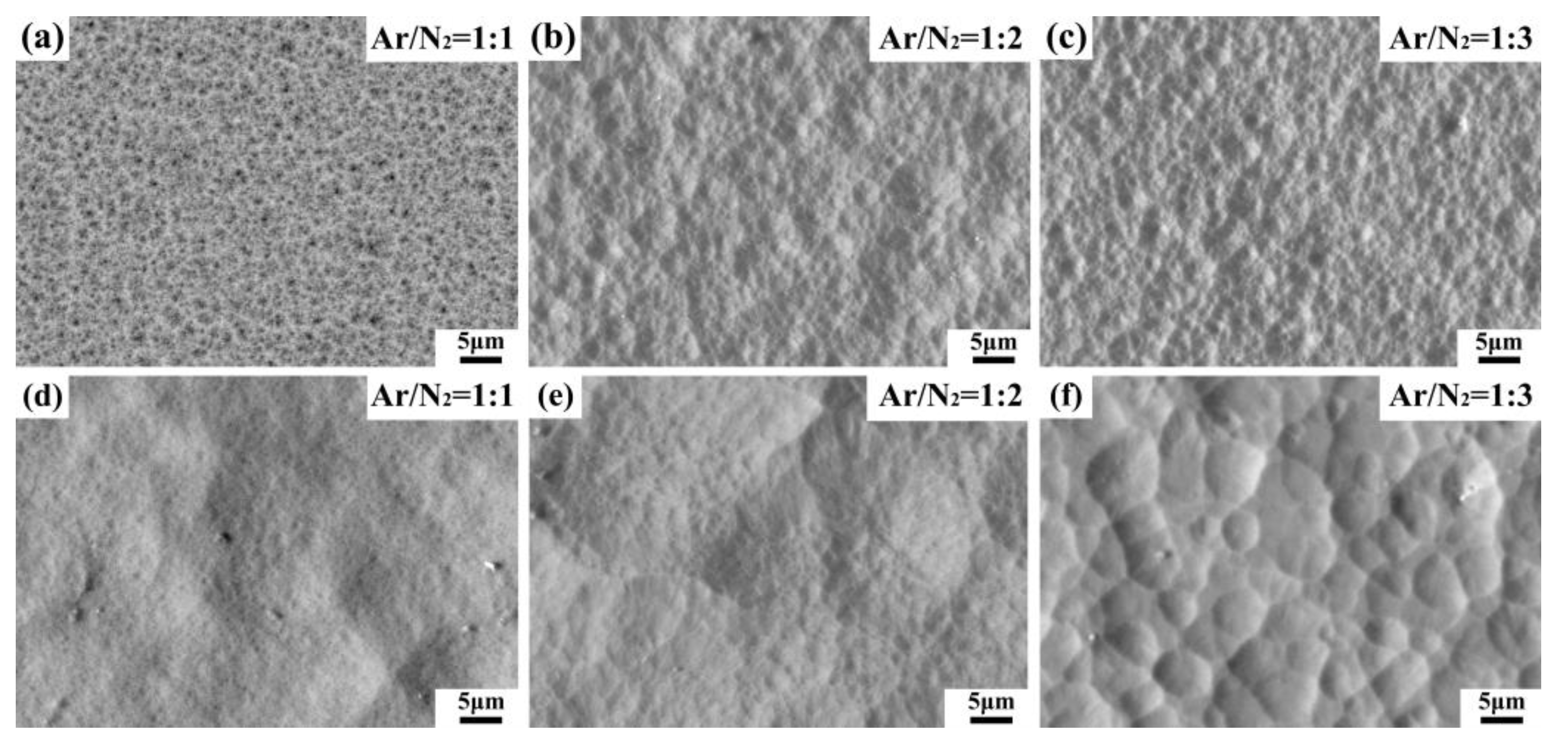
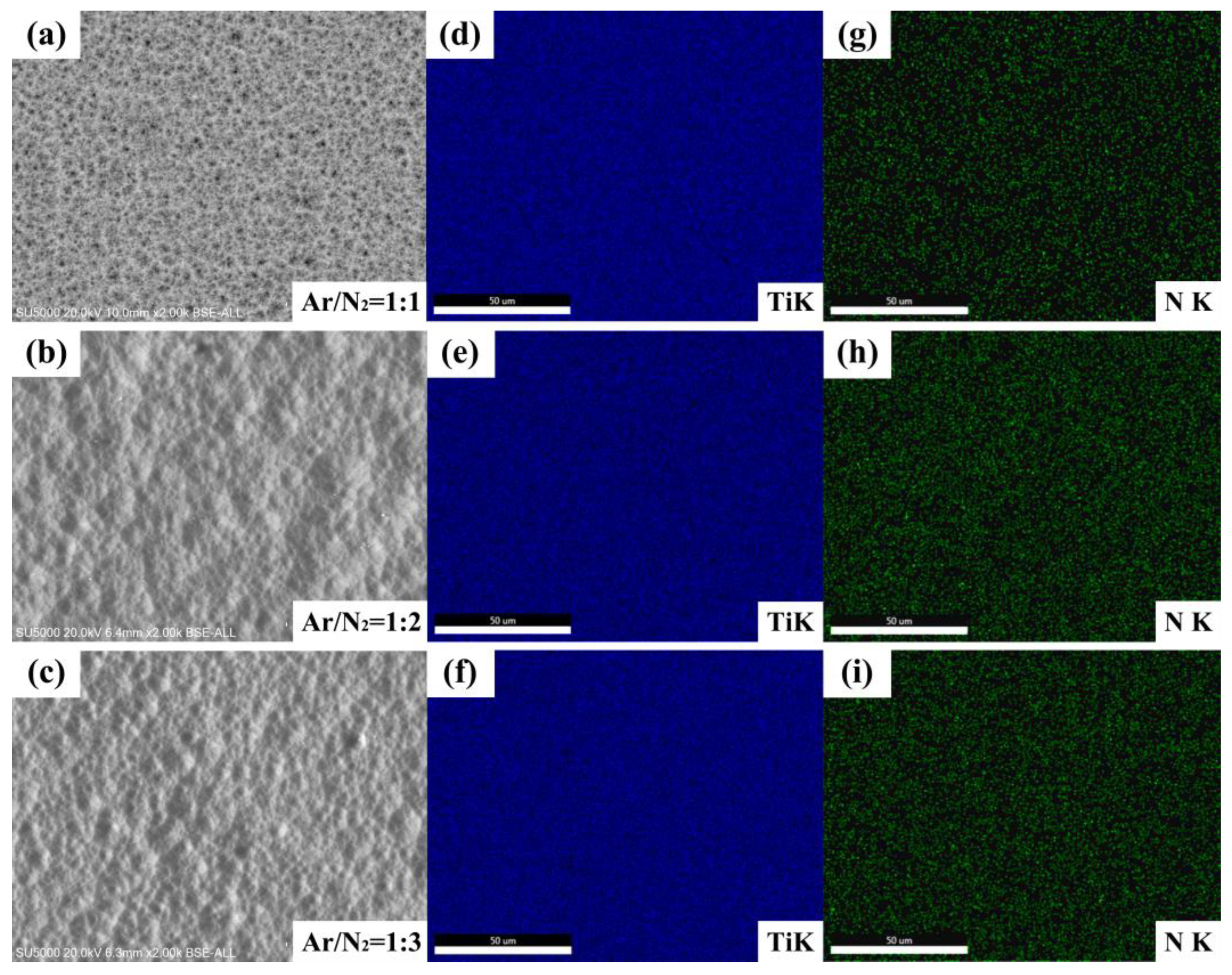
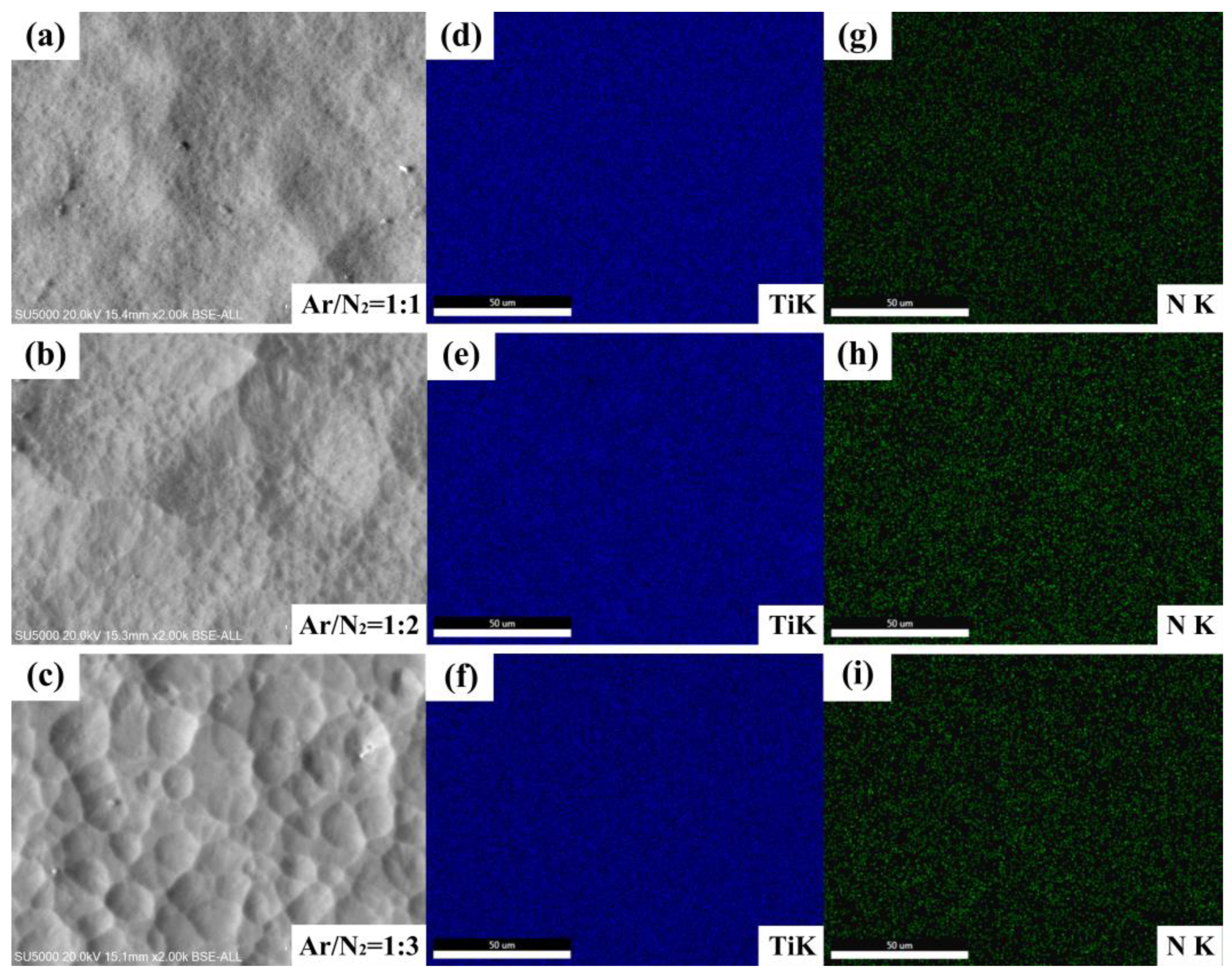
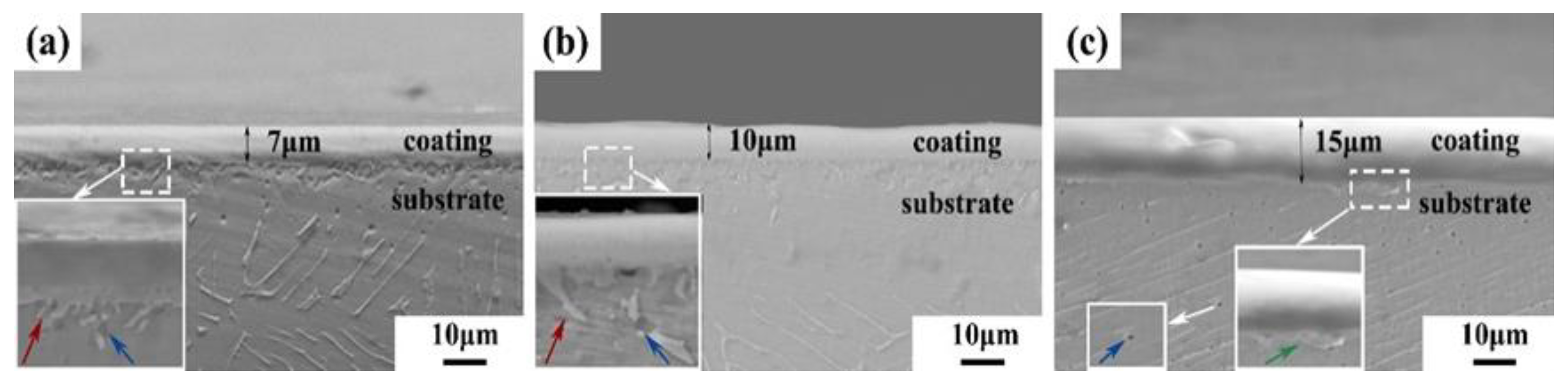
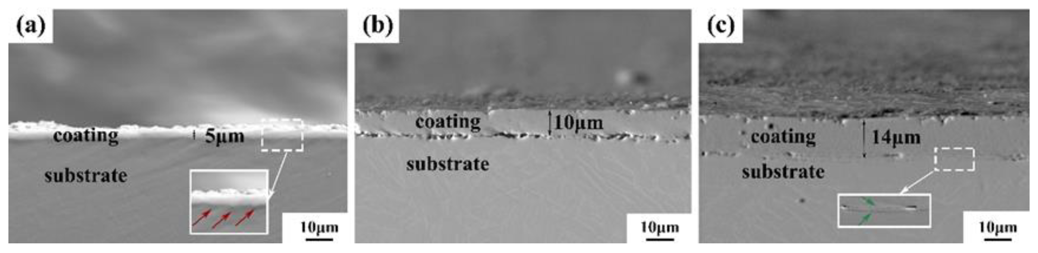
With the increasing concentration of N, the probability of the active particles being sputtered out increases, and more active particles are sputtered onto the surface of the specimen, promoting the growth of honeycomb structures; the honeycomb and island structures on the surface of the specimen increased, and the thickness of the coating also increased. The coating thickness of the BTi-62421S Ti alloy specimen was always thicker than that of the TC4 Ti alloy specimen. The optimum alloy specimen is the BTi-62421S Ti alloy at an Ar/N2 flow ratio of 1:3, with a coating thickness of 15 μm;
(2)
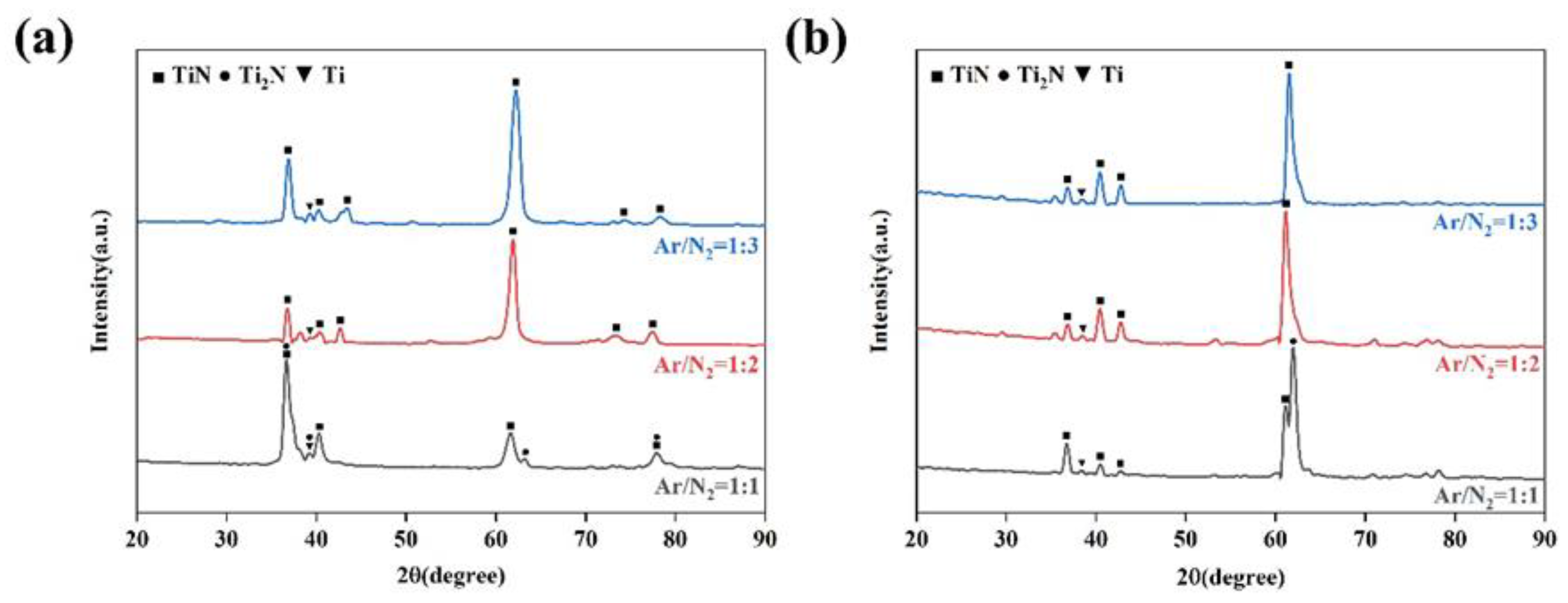
When the N concentration content is low, the main phases of the coating are composed of TiN and Ti2N, while the appearance of Ti2N was owing to the absence of TiN due to insufficient nitrogen content, and the main diffraction peak is located at around 37°; when the N concentration content increases, the main phases of the coating are all replaced by TiN, while the position and intensity of the main diffraction peaks of the phases also change significantly, and the main diffraction peak is located at around 62°;
(3)
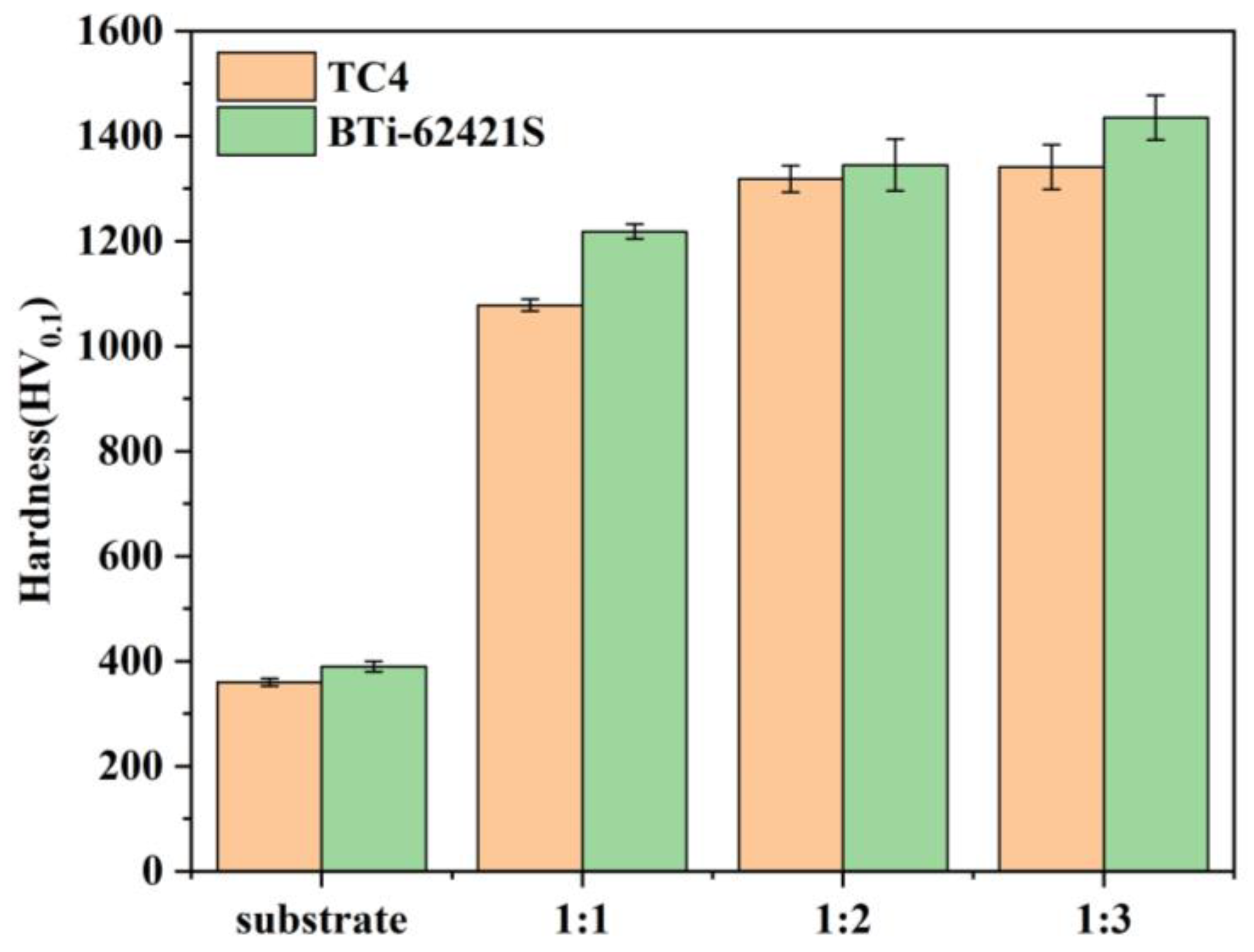
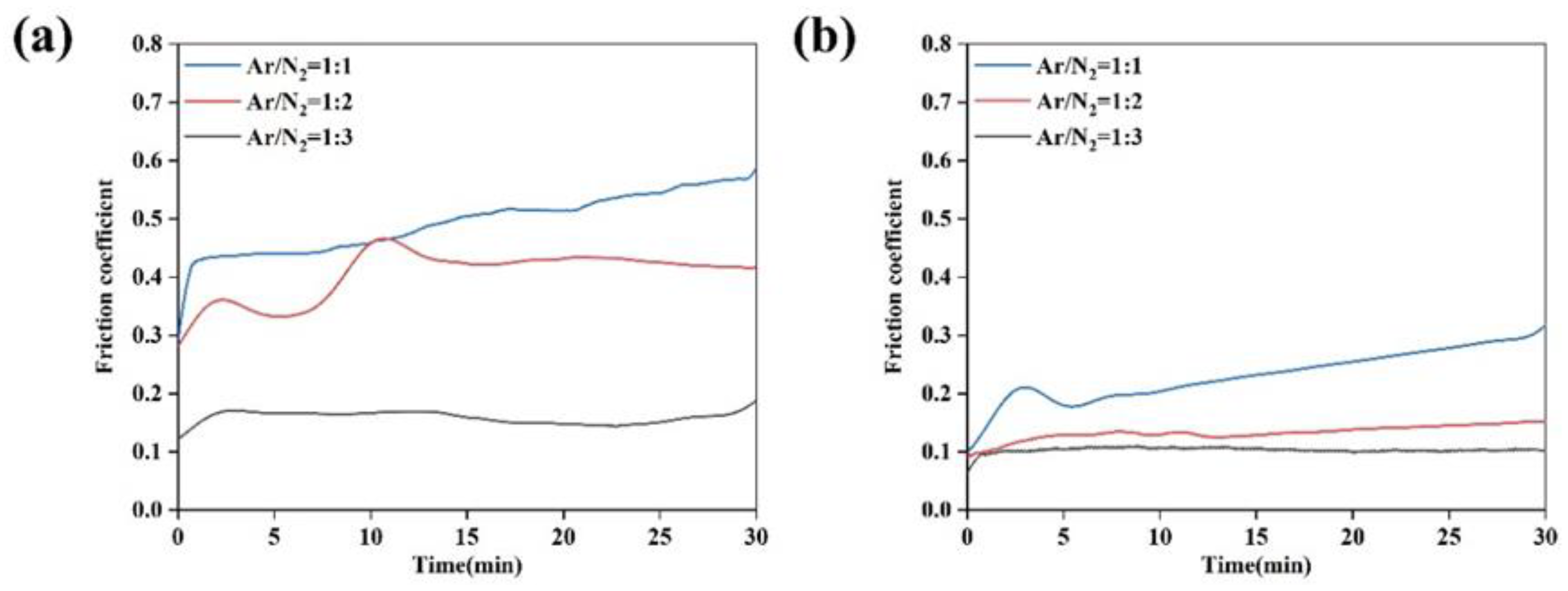
With increasing N concentration, the hardness of the coating showed a negative correlation with the friction abrasion coefficient; the micro-Vickers hardness of BTi-62421S Ti alloy was always higher than that of TC4 Ti alloy, but the friction coefficient of TC4 was generally lower than that of BTi-62421S Ti alloy. Based on the above analysis, the optimum alloy specimen is the BTi-62421S Ti alloy at an Ar/N2 flow ratio of 1:3, which has a microhardness of 1435 HV0.1 and an average friction coefficient of 0.154.

Author Contributions

Data curation, writing—review and editing, writing—original draft, Y.N.; methodology, conceptualization, funding acquisition, Z.Z.; methodology, conceptualization, Z.Y.; project administration, M.C.; methodology, conceptualization, B.D. All authors have read and agreed to the published version of the manuscript.

Funding

Graduate Innovation Project of Shanxi Province (Grant No. 2021Y593).

Institutional Review Board Statement

Not applicable.

Informed Consent Statement

Not applicable.

Data Availability Statement

Data is contained within the article.

Acknowledgments

The Authors also thank the Magnesium-based deep processing technology in the engineering research of the Ministry of Education.

Conflicts of Interest

All authors were involved in the study. The authors declare that there is no competitive economic interest.

References

  1. Peng, X.M.; Xia, C.Q.; Liu, Y.Y.; Wang, J.H. Surface molybdenizing on titanium by halide-activated pack cementation. Surf. Coat. Technol. 2009, 203, 3306–3311. [Google Scholar] [CrossRef]
  2. Peng, X.M.; Xia, C.Q.; Dai, X.Y.; Wu, A.R.; Dong, L.J.; Li, D.F.; Tao, Y.R. Ablation behavior of NiCrAly coating on titanium alloy muzzle brake. Surf. Coat. Technol. 2013, 232, 690–694. [Google Scholar] [CrossRef]
  3. Copland, E.H.; Gleeson, B.; Young, D.J. Formation of Z-Ti50Al30O20 in the sub-oxide zones of γ-TiAl-based alloys during oxidation at 1000 °C. Acta Mater. 1999, 47, 2937–2949. [Google Scholar] [CrossRef]
  4. Urtekin, L.; Kucukturk, G.; Karacay, T.; Uslan, I.; Salman, S. An Investigation of Thermal Properties of Zirconia Coating on Aluminum. Arab. J. Sci. Eng. 2012, 37, 2323–2332. [Google Scholar] [CrossRef]
  5. Lawton, B. Thermo-chemical erosion in gun barrels. Wear 2001, 251, 827–838. [Google Scholar] [CrossRef]
  6. Shukla, P.; Awasthi, S.; Ramkumar, J.; Balani, K. Protective trivalent Cr-based electrochemical coatings for gun barrels. J. Alloys Compd. 2018, 768, 1039–1048. [Google Scholar] [CrossRef]
  7. Wei, D.; Zhang, P.; Yao, Z.; Chen, X.; Li, F. Double glow plasma surface Cr-Ni alloying of Ti6Al4V alloys: Mechanical properties and impact of preparing process on the substrate. Vacuum 2018, 155, 233–241. [Google Scholar] [CrossRef]
  8. Chen, X.H.; Zhang, P.Z.; Wei, D.B.; Huang, J.; Xuan, W. Surface modification of pure titanium by plasma tantalumising. Surf. Eng. 2013, 29, 228–233. [Google Scholar] [CrossRef]
  9. Wei, D.-B.; Zhang, P.-Z.; Yao, Z.-J.; Liang, W.-P.; Miao, Q.; Xu, Z. Oxidation of double-glow plasma chromising coating on TC4 titanium alloys. Corros. Sci. 2013, 66, 43–50. [Google Scholar] [CrossRef]
  10. Majumdar, J.D.; Mordike, B.L.; Manna, I. Friction and wear behavior of Ti following laser surface alloying with Si, Al and Si + Al. Wear 2000, 242, 18–27. [Google Scholar] [CrossRef]
  11. Schmidt, H.; Schminke, A.; Schmiedgen, M.; Baretzky, B. Compound formation and abrasion resistance of ion-implanted Ti6Al4V. Acta Mater. 2001, 49, 487–495. [Google Scholar] [CrossRef]
  12. Hu, W.; Liang, W.P. Double-glow plasma nitriding of TC4 titanium alloy. Heat Treat. 2021, 36, 7–13. [Google Scholar]
  13. Zhang, H.; Zhang, Z.; Zhang, X.; Li, B.; Ma, H.-H. High temperature deformation behavior of BTi-62421S alloy. Rare Metals 2011, 30, 492–496. [Google Scholar] [CrossRef]
  14. Geng, M.; He, G.; Sun, Z.; Chen, J.; Yang, Z.; Li, Y. Corrosion Damage Mechanism of TiN/ZrN Nanoscale Multilayer Anti-Erosion Coating. Coatings 2018, 8, 400. [Google Scholar] [CrossRef]
  15. Qiu, Z.; Zhang, P.; Wei, D.; Duan, B.; Zhou, P. Tribological behavior of CrCoNiAlTiY coating synthesized by double-glow plasma surface alloying technique. Tribol. Int. 2015, 92, 512–518. [Google Scholar] [CrossRef]
  16. Liu, Y.; Zhou, B.; Wang, H.; Gao, J.; Ma, Y.; Hei, H.; Wu, Y.; Yu, S. Corrosion properties of β-Ta alloyed Ti6Al4V by double-glow plasma surface alloying technique. J. Mater. Sci. 2021, 56, 6487–6498. [Google Scholar] [CrossRef]
  17. Cui, S.; Yi, Z.; Huang, J.; Dong, C.; Luo, J.; Ouyang, J.; Tao, X. The preparation and lubrication properties of a CrN/Cr multilayer using the double glow plasma surface alloying technique. Appl. Surf. Sci. 2022, 605, 154686. [Google Scholar] [CrossRef]
  18. Qi, Y.; Liang, W.; Miao, Q.; Yi, J.; Lin, H.; Liu, Y.; Ma, H. Role of the nitrogen ratio on mechanical properties and wear resistance of Crn/Fe functionally graded coating produced by double glow plasma alloying. Appl. Surf. Sci. 2022, 585, 152735. [Google Scholar] [CrossRef]
  19. Yu, S.; Wang, Y.; Gao, J.I.E.; Hei, H.; Wang, R.; He, Z. Tribological and corrosion behavior of Sic/TaxC bilayer coatings prepared on stainless steel surface by double glow plasma surface alloying technique. Surf. Rev. Lett. 2020, 27, 1950229. [Google Scholar] [CrossRef]
  20. Zhang, H.; Li, Z.; He, W.; Ma, C.; Chen, J.; Liao, B.; Li, Y. Damage mechanisms evolution of TiN/Ti multilayer films with different modulation periods in cyclic impact conditions. Appl. Surf. Sci. 2021, 540, 148366. [Google Scholar] [CrossRef]
  21. Chatterjee, S.; Abinandanan, T.A.; Chattopadhyay, K. Phase formation in Ti/Ni dissimilar welds. Mater. Sci. Eng. A 2008, 490, 7–15. [Google Scholar] [CrossRef]
  22. Lin, C.-M.; Kai, W.-Y.; Su, C.-Y.; Tsai, C.-N.; Chen, Y.-C. Microstructure and mechanical properties of Ti-6Al-4V alloy diffused with molybdenum and nickel by double glow plasma surface alloying technique. J. Alloys Compd. 2017, 717, 197–204. [Google Scholar] [CrossRef]
  23. Yang, H.Y. Preparation of Ti6Al4V Alloy Surface Plasma Ni Alloy Layer and Performance Research; Taiyuan University of Technology: Taiyuan, China, 2015. [Google Scholar]
  24. Xiao, B.; Liu, J.; Liu, F.; Zhong, X.; Xiao, X.; Zhang, T.F.; Wang, Q. Effects of microstructure evolution on the oxidation behavior and high-temperature tribological properties of AlCrN/TiAlSiN multilayer coatings. Ceram. Int. 2018, 44, 23150–23161. [Google Scholar] [CrossRef]
  25. Gahr, K.-H.Z. Wear by hard particles. Tribol. Int. 1998, 31, 587–596. [Google Scholar] [CrossRef]
  26. Yildiz, F.; Yetim, A.F.; Alsaran, A.; Efeoglu, I. Wear and corrosion behaviour of various surface treated medical grade titanium alloy in bio-simulated environment. Wear 2009, 267, 695–701. [Google Scholar] [CrossRef]
  27. Dréano, A.; Fouvry, S.; Guillonneau, G. A tribo-oxidation abrasive wear model to quantify the wear rate of a cobalt-based alloy subjected to fretting in low-to-medium temperature conditions. Tribol. Int. 2018, 125, 128–140. [Google Scholar] [CrossRef]
Figure 1. Basic principle diagram of double-glow plasma surface alloying technique [14].
Coatings 13 00933 g001
Figure 2. Surface microstructure of alloy specimens with different Ar/N2 flow ratios (ac) BTi-62421S titanium alloy (df) TC4 Ti alloy.
Coatings 13 00933 g002
Figure 3. EDS maps of BTi-62421S Ti alloy specimens with different Ar/N2 flow ratios (a) Ar/N2 = 1:1; (b) Ar/N2 = 1:2; (c) Ar/N2 = 1:3.
Coatings 13 00933 g003
Figure 4. EDS maps of TC4 Ti alloy specimens with different Ar/N2 flow ratios (a) Ar/N2 = 1:1; (b) Ar/N2 = 1:2; (c) Ar/N2 = 1:3.
Coatings 13 00933 g004
Figure 5. Phase composition of surface coatings analyzed by X-ray diffractometer (a) BTi-62421S; (b) TC4.
Coatings 13 00933 g005
Figure 6. Cross-sectional appearance of BTi-62421S alloy specimens with different Ar/N2 flow ratios (a) Ar/N2 = 1:1; (b) Ar/N2 = 1:2; (c) Ar/N2 = 1:3.
Coatings 13 00933 g006
Figure 7. Cross-sectional appearance of TC4 alloy specimens with different Ar/N2 flow ratios (a) Ar/N2 = 1:1 (b) Ar/N2 = 1:2 (c) Ar/N2 = 1:3.
Coatings 13 00933 g007
Figure 8. EDS analysis of cross-sectional coatings (ac) BTi-62421S (df) TC4.
Coatings 13 00933 g008
Figure 9. Micro-Vickers hardness of BTi-62421S and TC4 Ti alloy specimens with different Ar/N2 flow ratios.
Coatings 13 00933 g009
Figure 10. Friction coefficients of alloy specimens with different Ar/N2 flow ratios (a) BTi-62421S (b) TC4.
Coatings 13 00933 g010
Figure 11. Microstructure of friction abrasion of BTi-62421S alloy specimens with different Ar/N2 flow ratios: (a) Ar/N2 = 1:1; (b) Ar/N2 = 1:2 (c); Ar/N2 = 1:3.
Coatings 13 00933 g011
Table 1. The che SINTER LAND INC.mical compositions of BTi-62421S alloy [13].
TiAlSnZrMoNbSi
Bal.5.902.104.001.201.900.36
Table 2. The chemical compositions of TC4 alloy.
TiAlVFeCONH
Bal.5.904.200.270.010.140.010.02
Table 3. The parameters of double-glow plasma nitriding experimental.
Experimental ParametersWorkpiece Pole VoltageSource VoltageTarget-to-Cathode DistanceInfiltration TimeAir Pressure
Parameter values600 V1000 V10 mm5 h35 Pa
Table 4. Micro-Vickers hardness of BTi-62421S and TC4 Ti alloy specimens with different Ar/N2 flow ratios.
SubstrateAr/N2 = 1:1Ar/N2 = 1:2Ar/N2 = 1:3
TC4360 HV0.11078 HV0.11318 HV0.11341 HV0.1
BTi-62421S390 HV0.11218 HV0.11345 HV0.11435 HV0.1
Disclaimer/Publisher’s Note: The statements, opinions and data contained in all publications are solely those of the individual author(s) and contributor(s) and not of MDPI and/or the editor(s). MDPI and/or the editor(s) disclaim responsibility for any injury to people or property resulting from any ideas, methods, instructions or products referred to in the content.

