1. Introduction
With the rapid development of advanced manufacturing technologies, it is necessary to improve the machining performance and quality for industrial purposes [
1,
2,
3]. The high-speed metal circular sawing machine is a marvel of efficiency and precision, deftly slicing through steel and non-ferrous metals with ease. Its widespread use in metallurgy and manufacturing is a testament to its versatility and effectiveness. Yet, with each pass of the sawblade comes a barrage of heat, a byproduct of the material removal process that poses a formidable challenge. Understanding the cutting temperature and its dependence on various parameters is essential for maintaining tool longevity and preserving the quality of the workpiece surface.
Due to the complicated measuring techniques that have been applied to address the engineering issues [
4], the method of measuring and studying the temperature in metal cutting is diverse, ranging from analytical, and experimental, to numerical modeling using finite elements.
The analysis involves using mathematical tools such as integral and Laplace transforms to determine the temperature of the cutting tool, however, these methods often rely on assumptions and may not reflect real-world scenarios. Studies have proposed three-dimensional analytical models, such as the work of Radulescu and Kapoor, that incorporate cutting force as a factor in determining transient cutting temperatures [
5,
6]. Analytical models for temperature distribution, such as the work of Young and Chou [
7], and Fang and Xu [
8], have also been proposed, making use of simplifying assumptions for ease of modeling and improved agreement with experimental data. Other works, such as the study by Mu et al., have utilized nonlinear and matrix perturbation theories to examine the interplay between the temperature field and centrifugal force in saw blade dynamics [
9]. Experimentation, on the other hand, involves the use of temperature sensors to directly measure the temperature, either through direct contact with the thermocouple method, or non-contact methods. Contact methods, such as the work of Wang et al. and Nasir et al., have yielded relatively accurate and direct temperature data [
10,
11], while other studies, such as the work of Chen et al., have employed inverse heat conduction methods and embedded thermocouples to determine heat flux and temperature fields [
12]. Werschmoeller et al. [
13] made use of PCBN inserts embedded with C-type thin film thermocouple arrays to study the correlation between temperature and cutting parameters in processing hardened steel workpieces, offering high spatial and temporal resolution in measuring internal temperature fields at the micro-scale.
The non-contact temperature measurement approach, often deemed more convenient than its contact-based counterpart, circumvents direct contact with the heat source, thus avoiding any potential perturbation of the heat flow distribution caused by the installation of a thermocouple. Commonly used in industrial settings, non-contact measurements often utilize the infrared radiation method, such as the infrared thermal imager method and the two-color pyrometer method [
14]. Li [
15] employed a far-infrared temperature measuring instrument to assess the temperature of the saw blade’s outer edge and the edge of the chuck during wood sawing operations, while also evaluating the thermal stress distribution along the radial direction of the saw blade. Fang [
16] utilized an infrared thermal imager to examine the temperature field of circular saw blades under varying working conditions and structures, combining heat transfer theory to analyze the factors that influence the temperature field and identify strategies for controlling it during the saw blade’s operational process. Lee et al. [
17] developed an online temperature monitoring system using an infrared thermal imager, near-field and far-field heat transfer models, and an artificial neural network trained by the model, to monitor the maximum steady-state temperature of the tool–chip interface during dry-cutting operations. Darwish and Davies [
18] utilized an infrared pyrometer to remotely measure the temperature of the tool–chip interface during high-speed milling, using the measured temperature as input for an inverse heat transfer model to calculate the heat flux and temperature distribution of the tool–chip interface. Despite its benefits, non-contact temperature measurement does face some limitations, such as interference from chip formation and coolant in the cutting process, as well as the sensitivity of measurement results to changes in surface emissivity under high-temperature metal cutting environments.
Toward explicating the impact of temperature on the dynamic stability of a saw blade, the numerical simulation provides the powerful tool to solve this problem [
19,
20,
21,
22,
23,
24,
25,
26,
27], so that the finite element method delves into the intricate relationships between the sawing process and the generation of cutting heat by simulating the actual scenario with the finite element method and analyzing the thermal stress distribution of the saw blade. Through the utilization of thermal transient analysis in ANSYS, Wang et al. [
10] erected a simulation model of diamond wire sawing single crystal silicon, wherein the heat generated by the sawing process is transmitted to the workpiece through the point of contact between the serration and the workpiece. In this model, the part of the workpiece that has been sawed and removed is designated as a “death” unit, simulating the state in which the material of the workpiece has been excised, thus forming a newly minted workpiece surface. At the same time, a heat flow load is appended to the surface of this newly formed workpiece, while the former heat flow load area transforms into a heat convection load area. In a quest to understand the interplay between temperature, centrifugal force, and the transverse stiffness of circular saw blades, An et al. [
28] resorted to a nonlinear finite element method to build a mechanical model of four representative circular saw blade matrix structures. The study aimed to decipher the variation of transverse stiffness under the impact of temperature and centrifugal force, as well as the combination of both. Zhang et al. [
29] delved into the effect of sawing heat production and conducted an analysis of stress and strain on the composite circular saw blade, revealing that the maximum thermal stress was observed at the welding point and the outer edge of the segment. Wang et al. [
30] pursued an investigation of the sawing performance of circular saw blades with and without copper-embedded design on the saw body groove and measured fixed-point temperature, lateral swing, and noise parameters of wood circular saw blades. The findings were intertwined with the distribution and computation of finite element thermal stress fields. Mote et al. [
31] examined the temperature difference between two concentric annular regions on the saw blade’s surface, utilizing the critical speed stability theory of circular saw blades to predict the optimal temperature condition. Experiments validated the effectiveness of feedback control of sawing temperature in reducing blade vibrations, thus improving machining accuracy and stability. Despite the potency of finite element numerical methods, defining material properties and setting boundary conditions is a challenging task, which can render it difficult to precisely mirror the actual situation when solving nonlinear problems arising from material properties, deformation, and multi-coupling fields.
Thus, this paper is going to explore the importance of sawing in the metal-working industry and the role of cutting temperature in determining tool durability and machined component surface quality. Specifically, the study aims to compare cutting temperature in circular sawing using two different methods: a semi-artificial thermocouple method and an implanted thermocouple wire method. The implanted thermocouple wire method is designed to accurately measure the transient temperature of circular saw blade teeth under varying sawing conditions. To improve the accuracy of the results, the study also incorporates finite element simulation to correlate with the experimental data. The unique aspect of this study is the integration of two experimental techniques to measure temperature in both the tool–workpiece interface and circular saw blade teeth, which strengthens the validation of the numerical model’s ability to predict sawing temperature. As a result, this study can contribute to future optimization research aimed at refining sawing process parameters and tool life by partially replacing complex and time-consuming experimental approaches with numerical simulation.
2. Experimental Work
2.1. Experimental Setup
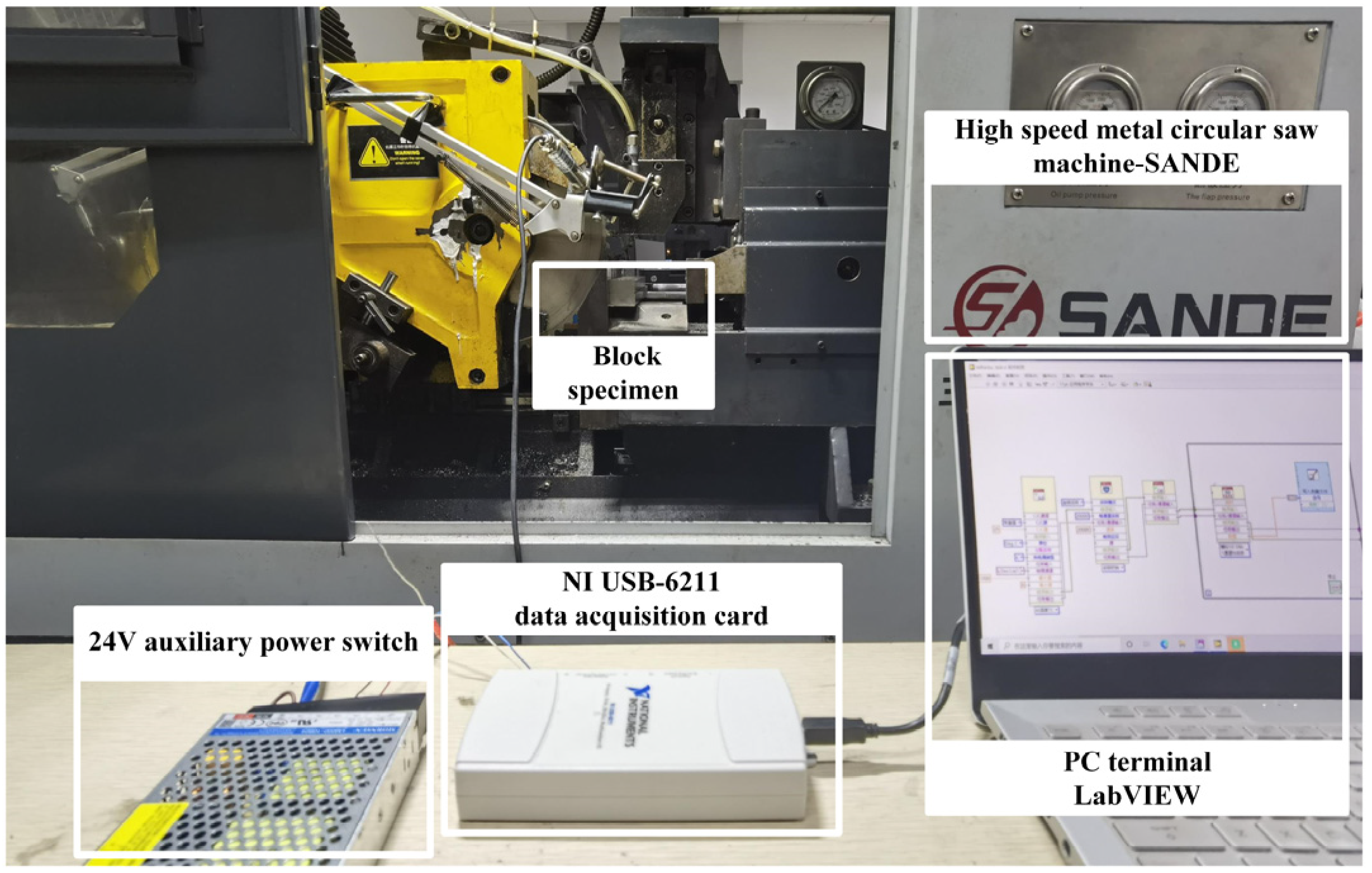
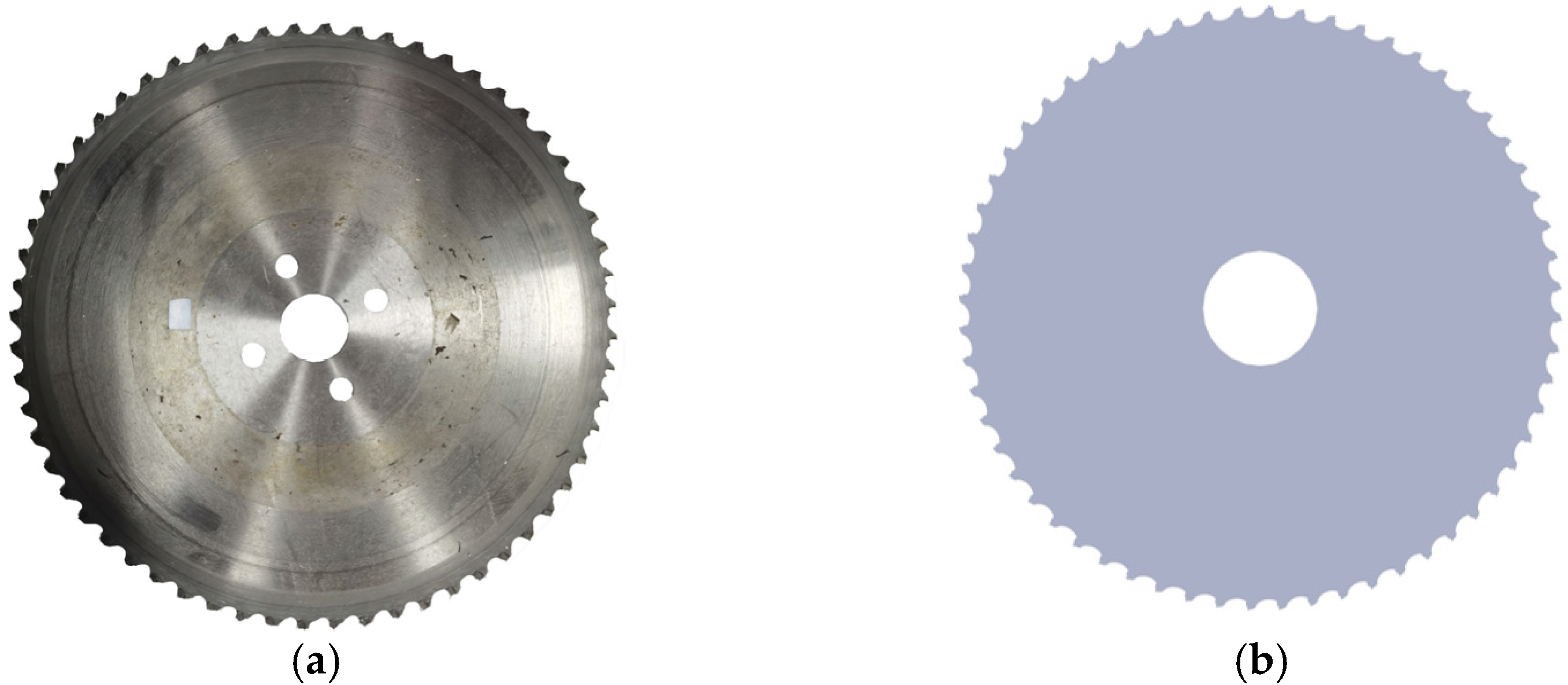
The enigmatic dry sawing examination was conducted utilizing the enigmatic SANDE emblem of a high-velocity metal circular saw apparatus, boasting a prodigious 7.5 kw of power and the enigmatic model SD-70R. The material utilized for the workpiece was none other than the resilient 45 steel bar, and the tool of choice was a 60-tooth carbide tip circular saw blade (of the renowned Hirono brand). The outer diameter of the saw blade stands at a formidable 285 mm, while the thickness of the base plate and serrated tooth edge both impress with dimensions of 1.7 mm and 2 mm, respectively. The data acquisition system, specially crafted for this study, is depicted in
Figure 1, featuring the ability to measure temperature through the utilization of both semi-artificial and dynamically artificial thermocouples.
The enigmatic assembly that constitutes the data acquisition system is a complex configuration, meticulously composed of a NI USB6211 model data acquisition card, a supplementary power source, and computer software that operates on a LabVIEW platform. The system, in its attempt to measure the thermoelectric potential signal, employs a direct sampling method that retrieves millivolt level signals. The acquired signals are then subject to a rigorous conversion process, where the standard thermocouple temperature calibration curve is employed to translate the potential values into temperature readings that can be recorded and analyzed.
2.2. Experimental Procedure
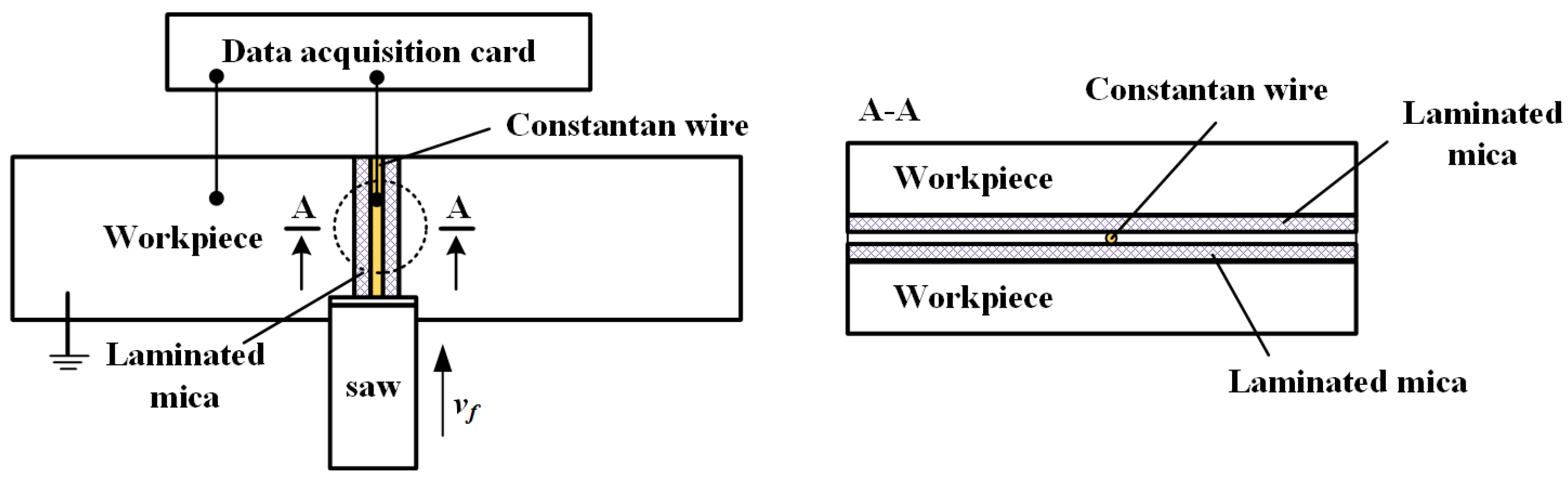
The schematic diagram of the semi-artificial thermocouple temperature measurement method using block specimens is depicted in
Figure 2. The process begins with dividing the pre-cut workpiece into blocks, with the thermocouple being embedded directly on the sawing path between the two blocks. The authors chose to use constantan wire for their experimental thermocouple, with a starting diameter of 0.5 mm and a width after rolling of 0.85 mm. To ensure insulation between the workpiece and the workbench, as well as between the thermocouple wire and the workpiece, a thin insulating mica sheet with a thickness of 0.02 mm is used. The experiment was conducted using 45 steel workpieces of 30 mm × 30 mm, with dry cutting employed to eliminate any interference from cutting fluid on the temperature measurement signal.
The sawing process reveals a complex interplay between the constantan wire, the mica sheet, and the workpiece, as the serrated tip reaches the clamping surface. The aftermath of this momentous encounter results in a spectacular transformation, as the constantan wire is severed and the mica sheet is destroyed, causing the wire to overlap on the workpiece’s surface and form a thermocouple loop. This loop is comprised of two poles—one from the constantan wire and one from the workpiece—that work together to provide valuable temperature measurement information. The measurement point for this method is located in the sawing arc zone, making it ideal for characterizing the surface temperature of the workpiece in this area. The temperature signal captured by this method provides a detailed and in-depth understanding of the temperature dynamics of the workpiece surface in the sawing arc zone.
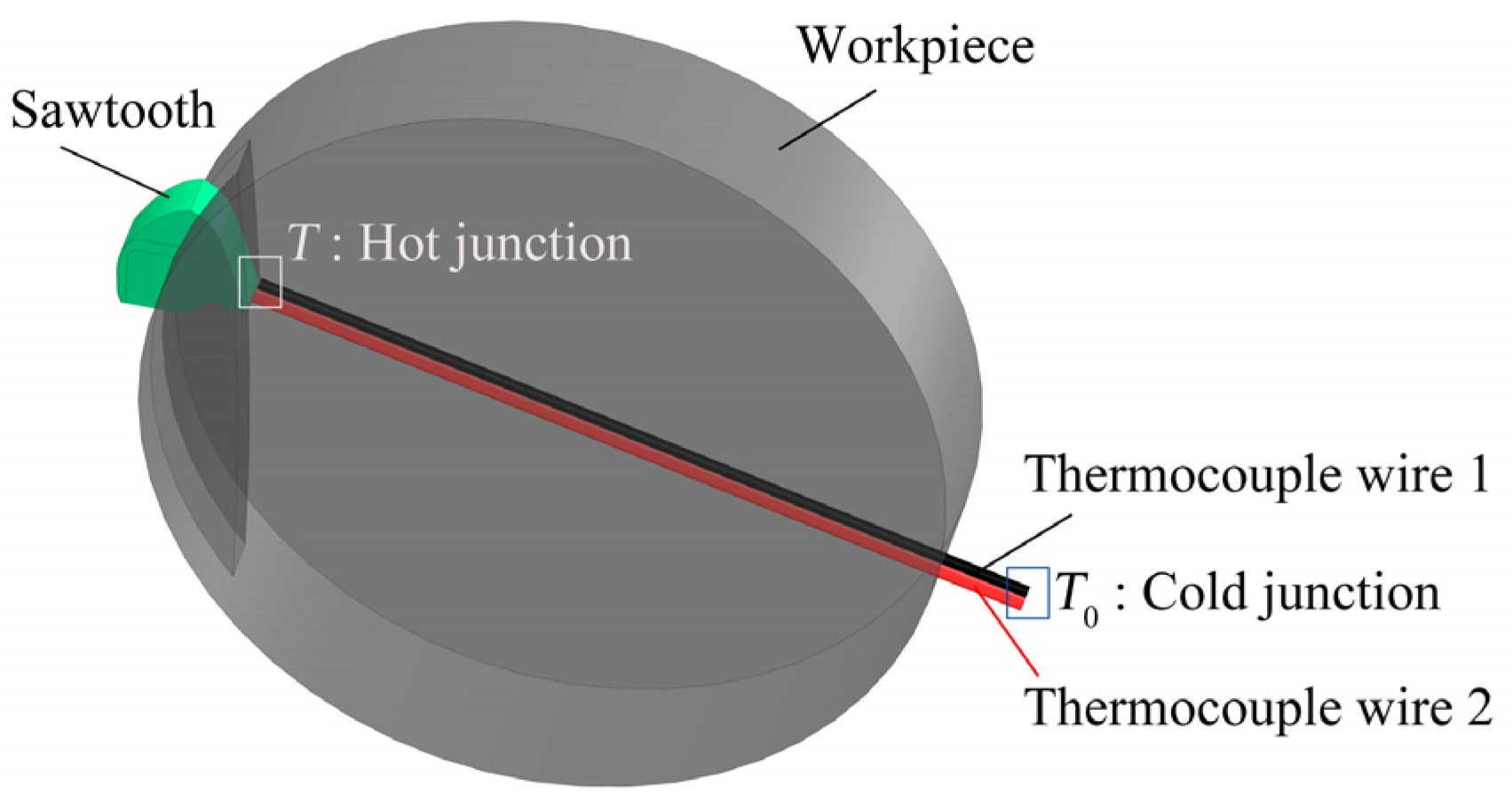
The method of dynamic contact artificial thermocouple for block specimens, which was chosen after a thorough consideration and analysis of the intricacies of intermittent material removal in high-speed metal circular saw cutting, represents a new and innovative approach to measuring the temperature of the sawtooth cutting tip. Based on traditional artificial thermocouple design, this dynamic method adds an extra layer of complexity, reflecting the dynamic nature of the cutting process. The temperature measurement method for the sawtooth tip, as depicted in
Figure 3, is made possible through the use of this dynamic embedded artificial thermocouple, offering a theoretical understanding of the temperature of the cutting tip.
With an eye towards the intricate and intricate nature of high-speed metal circular saw cutting, the design of the dynamic contact artificial thermocouple method for block specimens was devised, aimed at measuring the temperature of the sawtooth cutting tip. By combining two enameled thermocouple wires into a standard thermocouple, and closely clamping it into the workpiece while ensuring mutual insulation, the temperature value of the serrated tool and cutting zone can be determined by measuring the output thermoelectric power of the thermocouple circuit. A mica sheet is interposed between the thermocouple wire and workpiece to preserve insulation, even as the hydraulic clamping device damages the enamel layer. Upon being simultaneously cut by the sawtooth, the insulation layer and the two thermocouple wires become connected, forming the hot end of the circuit with a very small distance between them. The cold end of the two wires is kept at a temperature of 20 °C, thus enabling the standard thermocouple to generate thermoelectric power in response to the sawtooth cutting, and ultimately yielding a temperature value through the thermoelectric power–temperature conversion function of the standard thermocouple.
This method of dynamically forming a hot end with the sawing process sets it apart from the traditional artificial thermocouple approach, where the hot ends of the two thermocouple wires are welded together. The result is a more suitable means of measuring the tooth tip temperature of sawtooth sawing throughout the process of high-speed metal circular sawing, which acts as the sawing heat source. Unlike artificial and semi-artificial thermocouples or natural thermocouples, this method eliminates the need to consider the properties of the workpiece or calibrate the temperature–thermopower relationship of the thermocouple. Instead, any thermocouple wire capable of forming a standard thermocouple can be selected, allowing for the temperature of the serrated cutter head to be tracked in real time as it changes with the sawing feed.
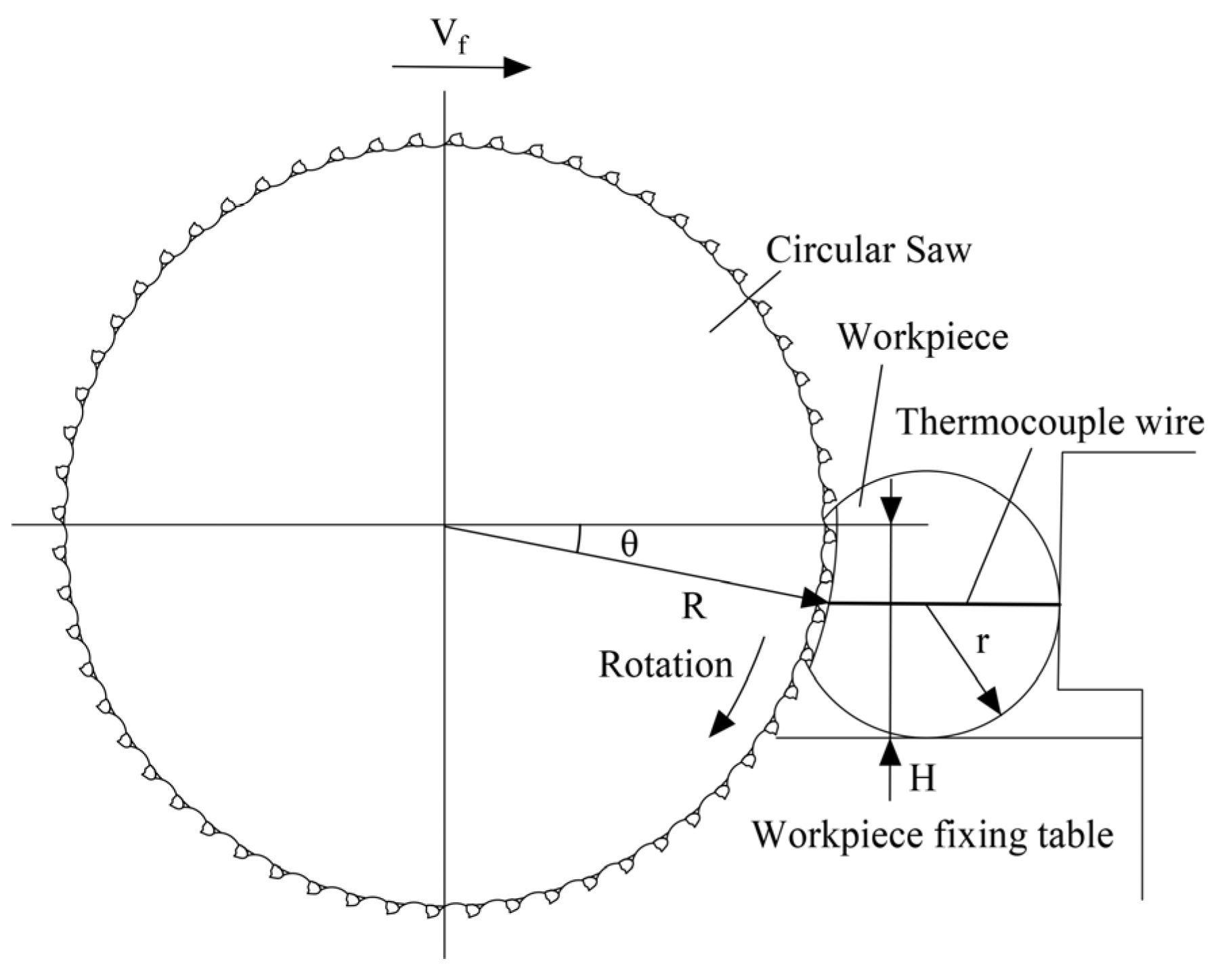
In this experiment, the arrangement of the saw blade tip, workpiece, and thermocouple wire is illustrated in
Figure 4. The symbol R represents the radius of the saw blade’s circular tip, H signifies the elevation variance between the saw blade center and the stable base plane of the workpiece, while r stands for the radius of the cylindrical steel workpiece.
With regard to the intricate setup of this experiment,
Figure 4 illustrates the intricate interplay between the saw blade’s tip, the workpiece, and the thermocouple wire. A towering height difference, marked by H, stands at 80 mm between the center of the saw blade and the fixed base plane of the workpiece. The workpiece, a sleek round steel with a radius of 15 mm, is meticulously positioned to interact with the thermocouple wire. The wire, with a diameter of 0.5 mm and composed of two kinds of enameled thermocouple wires arranged in tandem, is secured with a 0.2 mm thick mica sheet for insulation purposes. When the sawtooth tip of the saw blade cuts through the thermocouple wire, the length of the wire in contact, noted as
L, is precisely calculated from:
The length L of the thermocouple wire that makes contact, computed to be 0.57 mm, is incisively sliced by the saw blade at a cutting speed that peaks at 150 r/min, translating to a linear speed of 134.30 m/min at the sawtooth tip. With a mere 254.65 μs of sawing time, the data acquisition card, specifically the NI USB-6211, is able to obtain thermoelectric power. To ensure an efficient collection of the thermoelectric power peak, the sampling frequency has been adjusted to 20 kHz, and a minimum of 5 to 15 data points can be gathered during the cutting of the thermocouple wire.
4. Results and Discussion
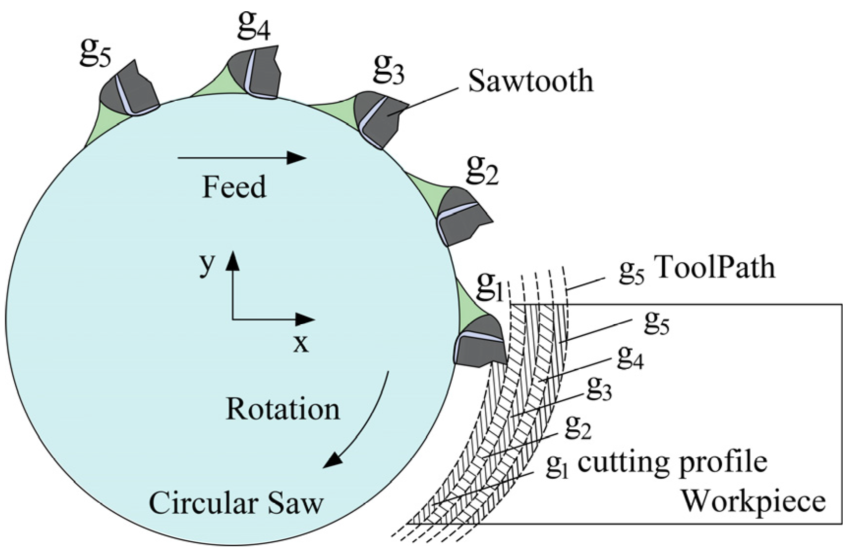
From a microscopic perspective, sawing is surprisingly similar to conventional planning, with its underlying mechanism being cutting through the interaction between sawtooth and workpiece. On a macroscopic scale, high-speed circular saw cutting, with its impressive material removal per unit and single-tooth back cutting, holds the key to the rapid cutting of large-scale workpieces. To provide a clearer representation of the sawing chip formation process, a schematic diagram is presented as shown in
Figure 10. In contrast to cutting techniques such as turning and milling, when using carbide circular saw blades for metal cutting, the instantaneous shear area of the sawtooth cutting edge is significantly smaller than the cutting area of the primary cutting edge, making the entire sawing process akin to a plane cutting process that is achieved through shear slip failure material removal.
As the sawing process initiates, the convergence of the sawtooth tip and the rake face with the workpiece results in the flow of surface metal along the edges of the saw blade towards the saw groove perimeter, initiating the primary stage of material removal by shear damage. The resistance faced by the metal to flow axially along the workpiece results in its radial flow towards the free surface, thereby forming a flash. While a fraction of the sawn metal manifests as flash and sawing marks along the saw groove, the bulk of it transforms into chips that traverse the front incline of the sawtooth before separating from the workpiece substrate. A thorough analysis of the chips procured from the site reveals the predomination of banded chips, with occasional instances of squeezed chips. Furthermore, high feed rates tend to result in the clustering of a larger number of banded chips.
4.1. Experimental Results and discussion
4.1.1. Semi-Artificial Thermocouple
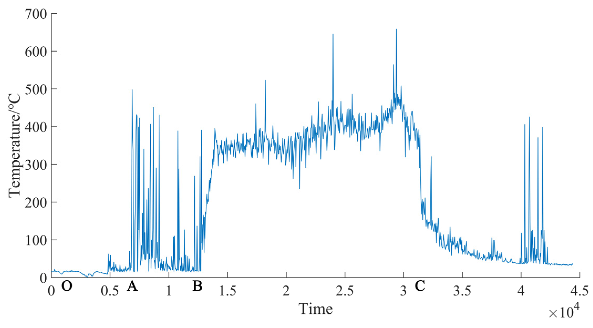
The temperature generated during the sawing process is comprised of two distinct elements, the temperature of the sawing zone, represented as
θA, and the temperature of the sawtooth tip, denoted as
θtooth. The temperature readings obtained via the semi-artificial thermocouple method predominantly represent the sawing zone temperature,
θA, and play a crucial role in determining the final quality of the workpiece surface. The methodology for gauging the temperature during sawing involves using a semi-artificial thermocouple, in which the workpiece (made of 45 steel) serves as the positive pole and a copper wire act as the negative pole, thereby enabling the generation of positive thermoelectric potential.
Figure 11 showcases the representative temperature curve obtained from the thermopower signal that was measured during the saw cutting of 45 steel. The cutting process in the O-A stage, as depicted in
Figure 11, has not yet commenced. Before the wire clamping surface reaches the sawing arc, the signal zero line remains flat, signifying that most of the interfering signals have been effectively eradicated. At point A, the tool comes into contact with the workpiece, producing a large impact signal with high amplitude. The B-C segment encompasses the entire sawing process. The large amplitude signal after point C arises from the contact electrification between metals at the end of sawing. As the sawtooth enters the sawing arc zone, the temperature curve displays densely arranged sharp pulse signals, indicating the temperature at the sawtooth cutting point. The starting and ending positions of the sharp pulse signal reflect the temperature variation range of the sawing arc zone. This study regards the inner envelope of the measured value as the average temperature of the workpiece’s surface and examines the effect of sawing process parameters on the temperature in the sawing area.
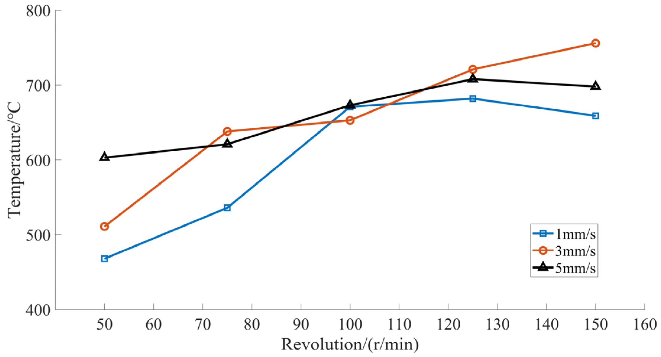
To investigate the relationship between the temperature in the sawing area and the blade speed, the sawing feed rate was varied at 1, 3, and 5 mm/s.
Figure 12 illustrates the impact of cutting temperature on blade speed under three feed rate conditions. As observed in
Figure 12, the sawing temperature exhibits an oscillating upward trend with the rise in saw blade speed. Analysis reveals that this trend is largely due to the increase in the number of serrated teeth participating in sawing per unit of time as the saw blade speed increases, causing the thickness of the single-tooth cutting layer to decrease. This leads to thinner strip chips produced by each tooth cutting and an increase in chip deformation energy per unit of material removed. Furthermore, while the contact between the saw teeth and the chip serves as the heat source during the sawing process, the chip remains in the groove between the two saw teeth and rotates with the saw blade, generating significant slip heat between the cutting and the workpiece until the saw teeth cut through the workpiece and the chip separates. As a result, an increase in saw blade speed also leads to increased slip heat of chips between teeth, a rise in the number of teeth producing slip action during cutting, and heightened friction, all contributing to a higher sawing temperature.
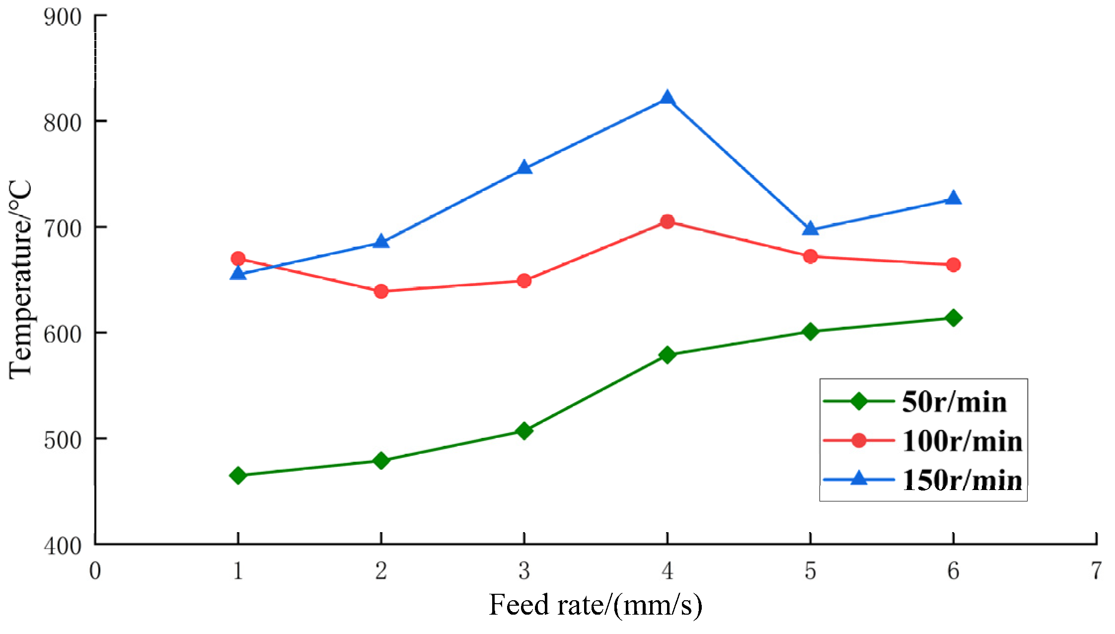
The study of the relationship between sawing temperature and feed rate is explored by fixing the saw blade speed at three different speeds: 50 r/min, 100 r/min, and 150 r/min. As revealed by
Figure 13, the graph illustrates the correlation between sawing temperature and feed rate, given the three blade speed conditions. It is apparent that a consistent blade speed sees a gradual rise in overall sawing temperature as feed rate increases. Below 3 mm/s, sawing temperature increases at a slow pace, yet with a smooth downward trend. However, once the feed rate surpasses 3 mm/s, the increase in sawing temperature intensifies. When feed rate exceeds 5 mm/s, the increase in sawing temperature slows down. This is due to the fact that increasing feed rate thickens the single-tooth cutting layer and therefore requires more cutting energy, causing a rise in temperature. Additionally, the movement of heat sources along the cutting path of the workpiece is accelerated and the single cutting completion time is reduced with an increase in feed rate, leading to a decrease in the recorded sawing temperature. As a result of these two factors, the sawing temperature displays an overall positive correlation trend as depicted in the figure. Yet, while reducing the feed rate reduces cutting temperature, it also reduces productivity—a critical factor in the sawing process. Thus, there is an optimal set of cutting process parameters that balances sawing temperature within an acceptable range while preserving sawing productivity.
4.1.2. Implanted Thermocouple
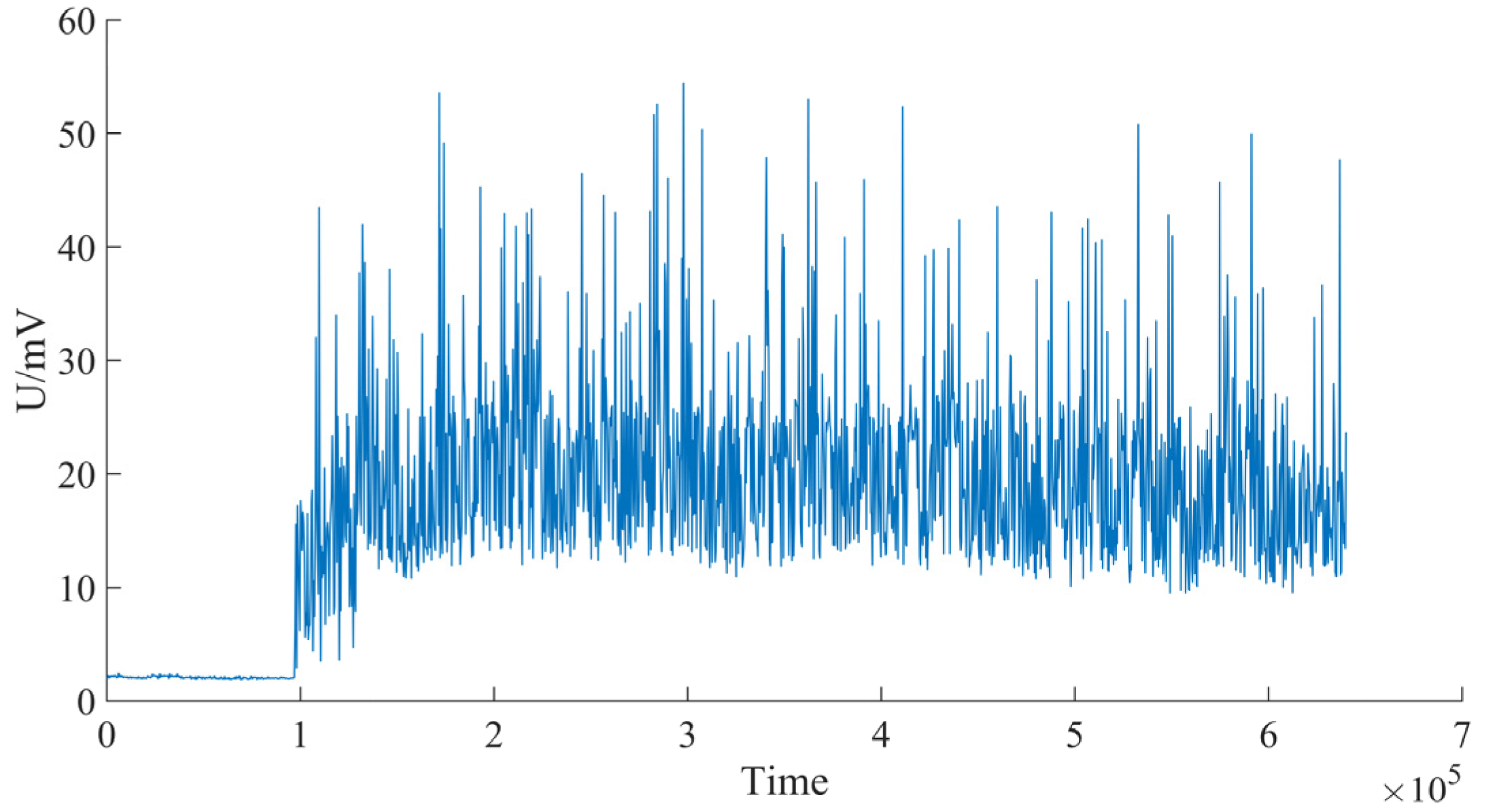
The temperature readings obtained through the sophisticated technique of embedded dynamic artificial thermocouple measurement primarily reflect the temperature of the sawtooth tip (
θtooth), which holds significant sway over the tool’s efficacy and longevity. The pulsating trend in temperature measurement, evident in the thermoelectric power curve depicted in
Figure 14, is a direct result of the intermittent nature of the sawing process.
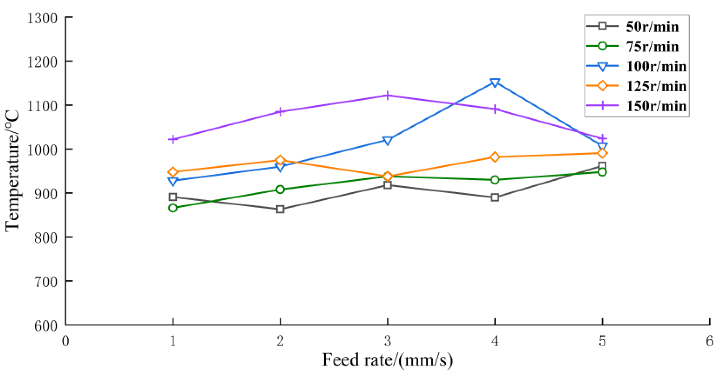
By delving into the investigation of the correlation between the temperature of the sawtooth tip, denoted as
θtooth, and the cutting process parameters, as specified in
Section 4.1.1 of this paper, the experiment was meticulously divided into two categories to unravel the impact of saw blade speed and feed rate on the temperature. By capturing the thermoelectric potential curve, the peak values of the thermoelectric potential were determined at 50 evenly spaced points and then, after undergoing a rigorous compensation and calculation process, the temperature values were obtained. Subsequently, the change curve of the temperature of the saw tip under diverse operating conditions was derived and is displayed in
Figure 15, presenting a clear representation of the connection between the temperature of the sawtooth tip and the cutting process parameters. As depicted in
Figure 15, the graph showcases the fluctuations of the average temperature of the saw blade tip while sawing 45 steel under varying operational circumstances, and it can be seen that the temperature slightly increases with the increase in feed rate, and it demonstrates that the feed rate would affect the temperature considered the process parameters in this study. It can be observed that the temperature measurement of the saw blade tip by the current method aligns with the temperature evaluation of the sawing zone obtained via the semi-artificial thermocouple technique described in
Section 3.2 of this paper. Despite the similarities in the overall trend, the temperature computed by the present method is considered to be that of the heat source, thus the peak temperature readings are considered in the analysis, leading to a higher overall average temperature as compared to the value obtained from
Section 4.1.1.
Amidst the experimental proceedings, it has been discerned that this methodology bears certain constraints. The interference present within the acquired signal could lead to an impact on the measurement outcomes. In several instances, this could even obscure the meaningful signal, rendering the results devoid of value. This occurrence is due to the thermocouple wires not being in a constant state of contact except for the exact moment when the saw teeth intersect the thermocouple wires during the cutting process. During the machining process, the serrated teeth are in continuous contact with the workpiece; thus, the thermocouple wire remains separated for the majority of the time, leading to the interference signal covering the entire process. Nevertheless, the amplitude of the interference is relatively smaller than the peak value, and as the peak mean value of the signal is adopted as a data parameter in this test, its impact can be disregarded.
4.2. Numerical Results and Discussion
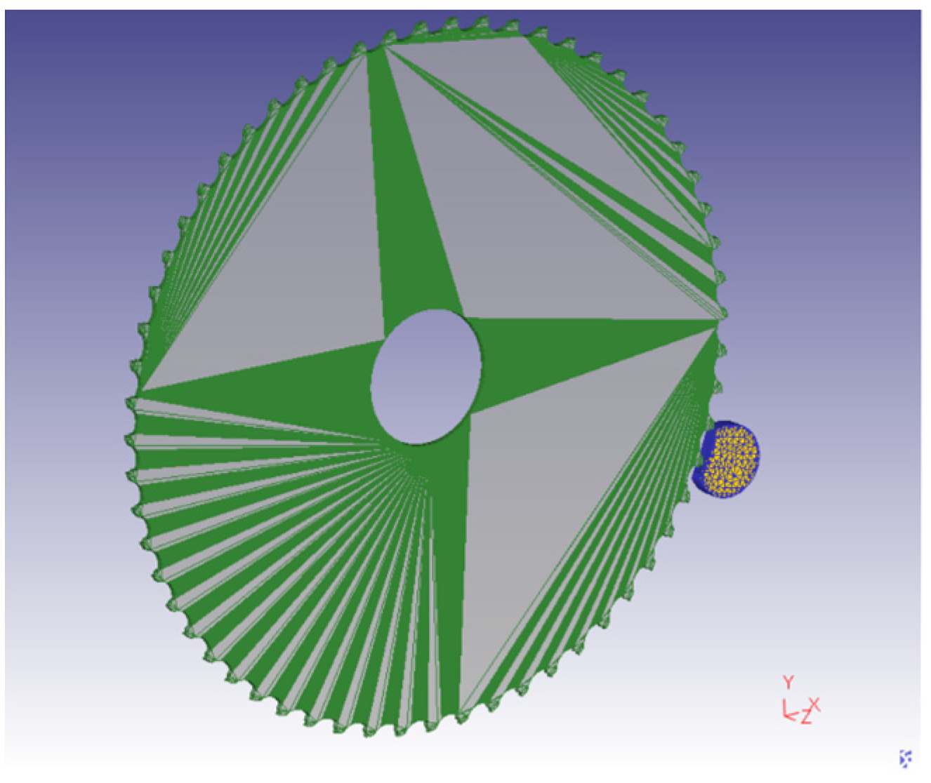
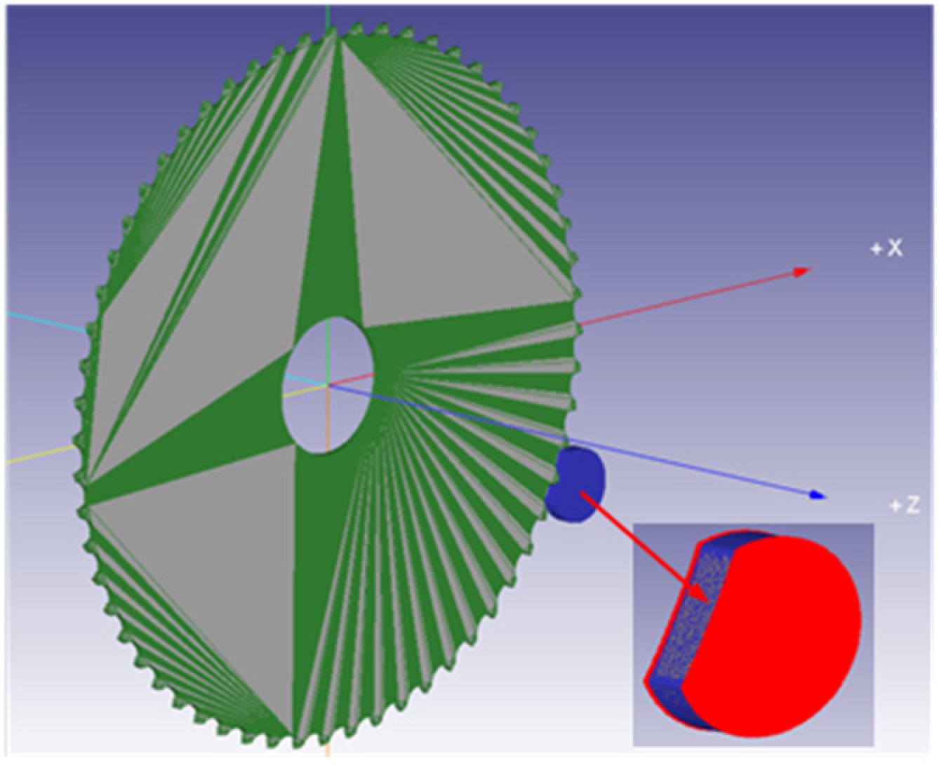
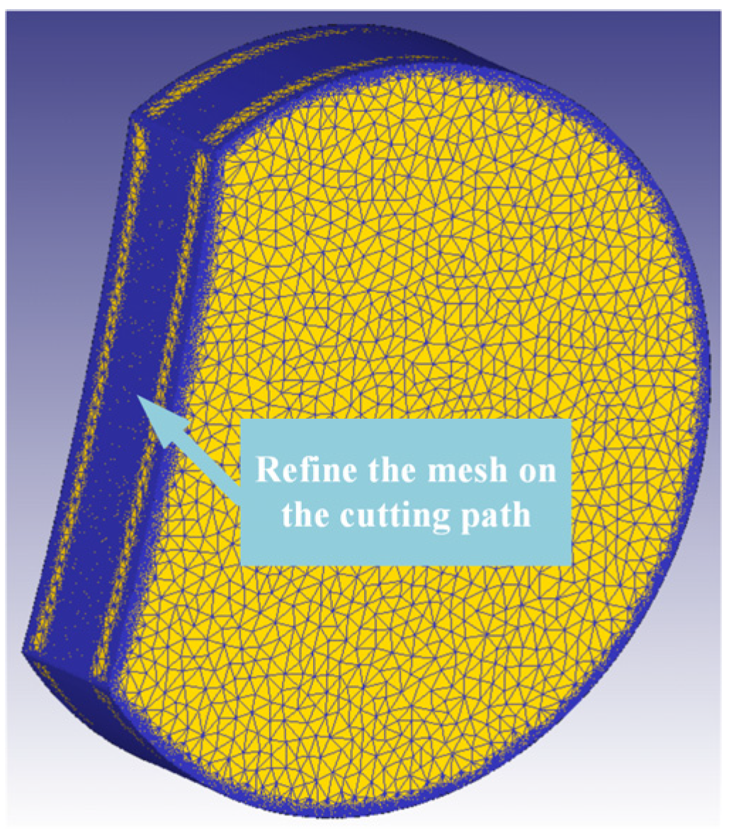
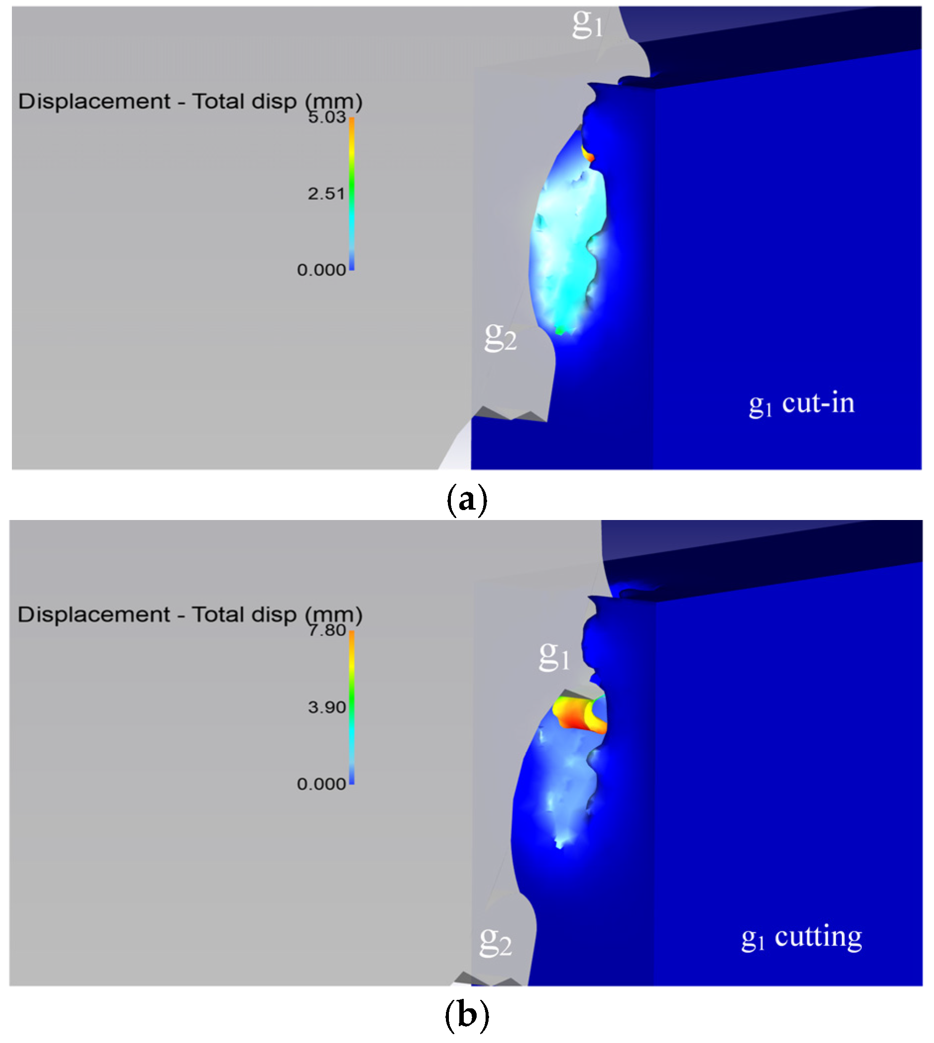
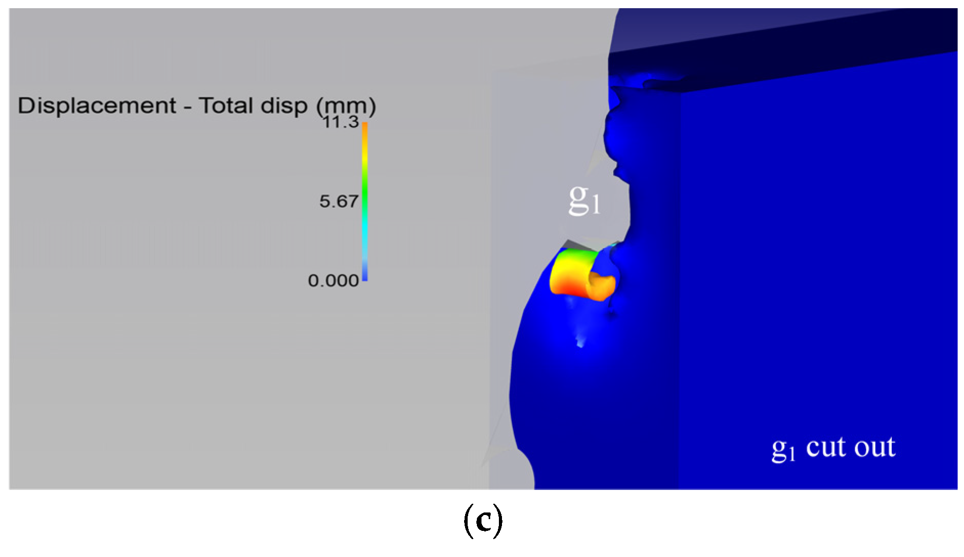
As illustrated in
Figure 16, DEFORM-3D was utilized to depict the simulation of cutting square and circular 45 steel workpieces with a circular saw. The visual representation demonstrates the metamorphosis of the workpiece subjected to the serrated g
1 of the circular saw blade, producing a sequence of chip separation and crimp deformation as a result of material deformation.
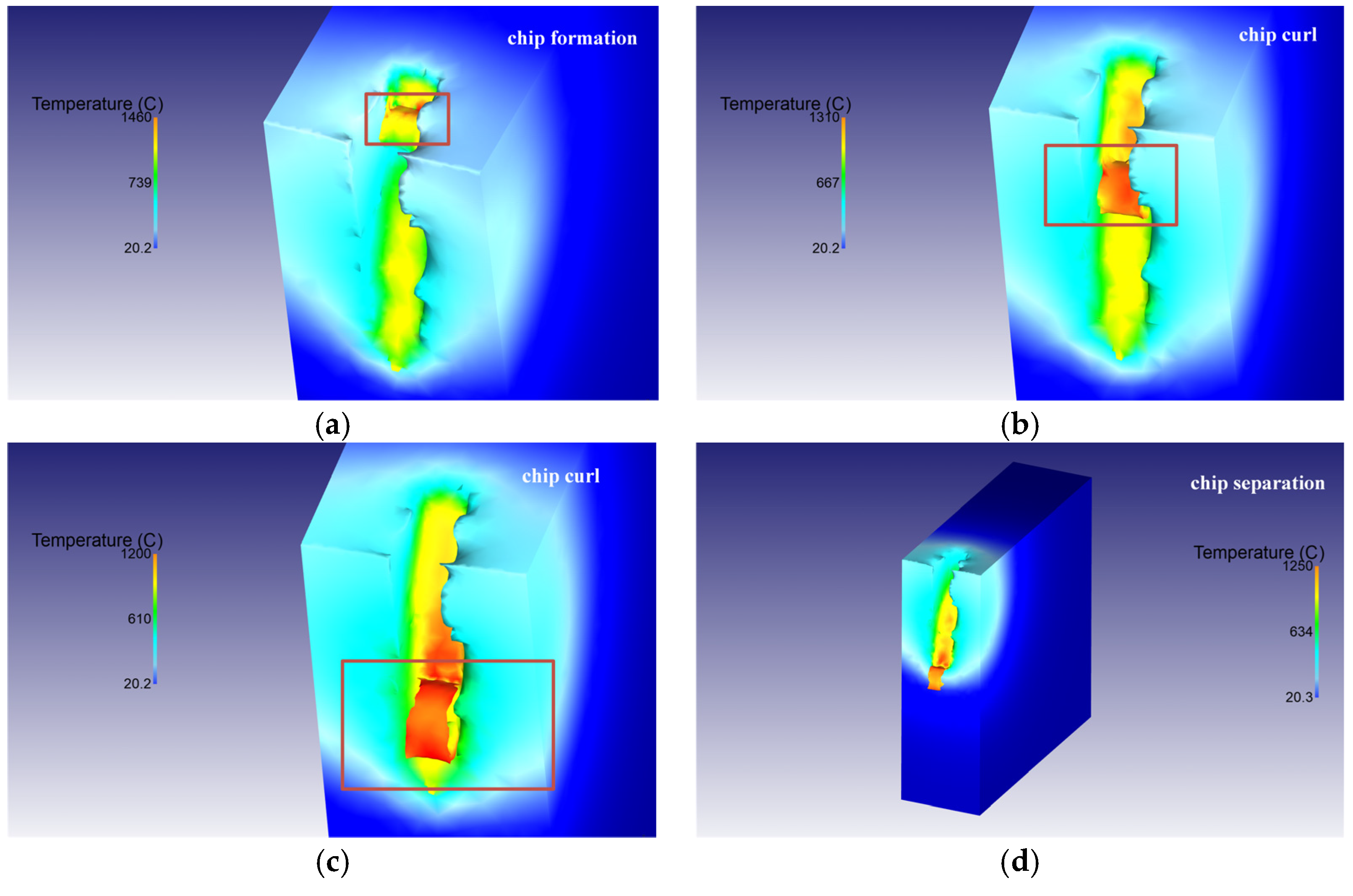
The art of sawing a square workpiece unveils a remarkable insight into the intricate temperature field changes that occur during single sawtooth cutting, as illuminated by
Figure 17. The process is characterized by the highest temperature concentrations around the tooth tip and cutting edge, which, despite being located on the rake face, remain a certain distance away from the cutting edge due to the intense tooth–chip interaction at this juncture. This interaction leads to the highest surface temperature of the workpiece being found at the bottom of the chip, where it encompasses a large area. The transient sawing temperature, which is highest along the entire root, can reach an astonishing 1300 °C. The cause of this heat, arising from the large amount of plastic deformation during the sawing process, stems from the friction between the serrated edge and the chip, and its inability to be transmitted in time, resulting in heat accumulation and elevated temperatures at the chip root. A comparison between the temperature distribution of the workpiece and the sawtooth illustrates that the heat generated during sawing is primarily located on the surface of the workpiece and is carried away by the chip.
The brevity of the single tooth cutting stage during actual machining is well-known. As the saw blade advances, the number of teeth involved in the cutting process increases and the saw groove takes shape. Given this, it is believed that simulating the temperature field of the workpiece’s saw groove surface provides a more accurate representation of the actual machining scenario. The aim of this study is to delve into the cutting temperature characteristics of the sawing process, investigate the impact of cutting process parameters on the temperature, and unravel its underlying principles, thereby lending crucial guidance for the judicious selection of cutting parameters. During circular sawing, a single sawtooth periodically cuts into and out of the workpiece, defining a cutting cycle composed of both cutting time and non-cutting time. Meanwhile, the workpiece surface experiences both the cutting stage and the non-cutting stage. The ratio between these times affects both the heating and cooling time of the sawtooth and the workpiece surface, thereby influencing the temperature of the sawing process.
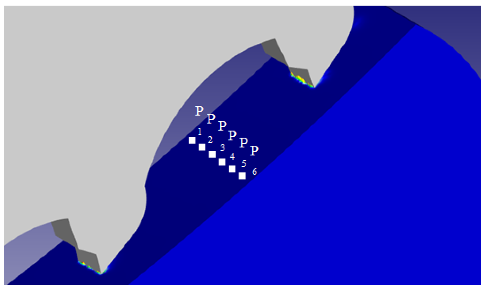
Investigating the temperature fluctuations of both the workpiece surface and the saw teeth during sawtooth cutting, researchers employed the cutting temperature point tracking technique to ascertain the temperature distribution along the cutting path, as depicted in
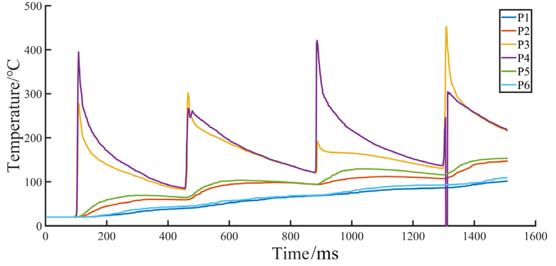
Figure 18. To further align simulation conditions with experimental surroundings, the distribution of temperature points considers the actual cutting path during temperature measurement experiments. With a blade speed of 50 revolutions per minute and a feed rate of 5 mm per second, the temperature curve generated from the point tracking simulation is depicted in
Figure 19. The surface temperature of the workpiece, due to its cutting characteristics of an intermittent cycle, manifests in a cyclical manner with a gradual decrease as the number of intermittent steps increases. As the sawtooth reaches the tracking point, the temperature begins to ascend, with the temperature at points P
3 and P
4 escalating sharply. The reason is that these two points are situated along the cutting path of the sawtooth where the material removal and tool–chip friction are most severe, thus generating a considerable amount of sawing heat. Conversely, the temperature changes at the remaining four points are primarily driven by heat conduction in the cutting arc zone through the workpiece, exhibiting a relatively stable fluctuation. As the sawtooth withdraws from its position of distribution, the temperature gradually decreases through heat dissipation and cooling until the next sawtooth enters the distribution position and starts cutting anew.
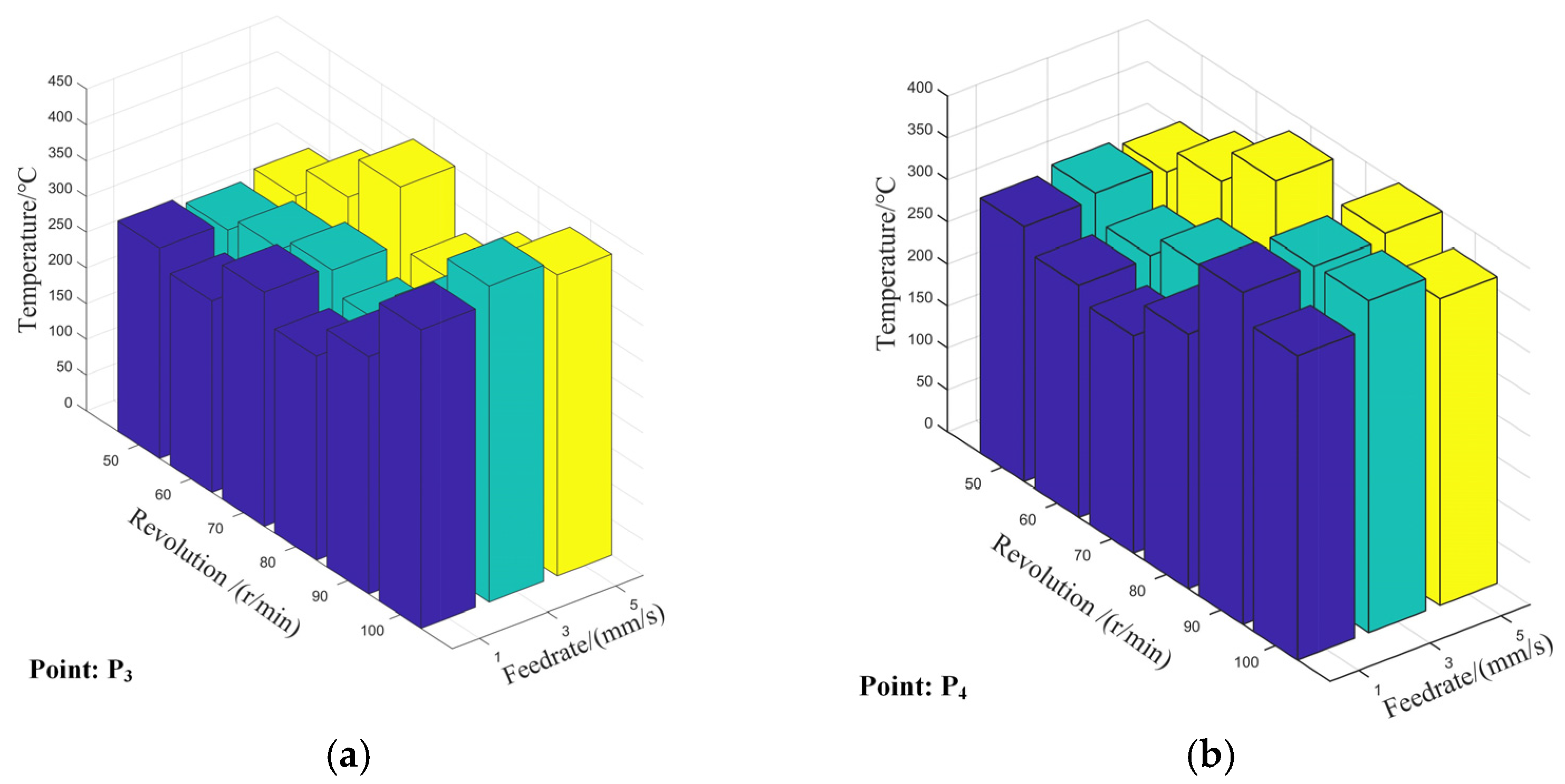
With a view to unraveling the impact of the fluctuating parameters of the cutting procedure on the simulated temperature of the cutting process, a full-scale study was conducted using a full-factor test design scheme. The results, as portrayed in
Figure 20, revealed the average value of the transitory maximum temperature of points P
3 and P
4, as they fluctuated with variations in the speed and feed of the saw blade. The simulation showed an interactive relationship between the sawing speed and feed rate, as an increase in saw blade speed at a constant feed rate led to a reduction in the thickness of the single-tooth cutting layer, resulting in a surge in tool–chip friction heat generation. As the cutting temperature rise of a single tooth was analyzed, it became evident that the relationship between speed, feed, and temperature was interactive. The heat production from material deformation and removal remained constant per unit of time, while the heat production from the tool–chip friction intensified. Hence, when seen from the perspective of the entire sawing process, the speed was found to be positively correlated with the sawing temperature. Furthermore, as the speed of the saw blade remained constant, an increase in the feed rate led to an increase in the thickness of the single-tooth cutting layer, and, therefore, the cutting temperature rose as the amount of material removal per unit of time increased. The two were, therefore, considered to be positively correlated.
5. Conclusions
In this paper, the temperature of 45 steel during dry sawing was monitored and analyzed utilizing a cemented carbide circular saw blade under diverse cutting conditions, and the results were verified through a finite element simulation. The conclusion that emerges from this study is as follows:
(1) An innovative system for acquiring sawing temperatures has been developed and implemented with remarkable success, providing valuable insights into the temperature changes that occur during the sawing process. The mean temperature of the arc zone in the workpiece was determined using a semi-automated thermocouple measurement technique, while the temperature of the sawtooth tip was obtained via an advanced, dynamic artificial thermocouple method that was seamlessly integrated into the system.
(2) The results of the temperature measurements obtained through our two methods, namely the semi-automated thermocouple and the embedded dynamic artificial thermocouple, show a general agreement, demonstrating a positive correlation between the sawing temperature and the two variables of saw blade speed and feed rate in the large-scale trend. However, this relationship is intricately interrelated and influenced by changes in the thickness of single tooth-cutting layers. Thus, there exists an optimal combination of cutting process parameters that balances the sawing temperature and productivity, thereby maintaining stability within reasonable ranges.
(3) The simulation results reveal a cyclical fluctuation in temperature along the workpiece surface and sawtooth, with a gradual decrease after an increase in the intermittent step. An examination of the temperature progression across the sawing process discloses a positive correlation between the saw blade speed and feed rate, and the sawing temperature, which concurs with the experimental temperature measurement results.


