
Surface Structure and Properties of Hydroxyapatite Coatings on NiTi Substrates
by
 , and
, and
Ekaterina S. Marchenko
1,
Kirill M. Dubovikov
1,
Gulsharat A. Baigonakova
1,
Ivan I. Gordienko
2 and
and
Alex A. Volinsky
1,3,* 1
Laboratory of Superelastic Biointerfaces, National Research Tomsk State University, Tomsk 634045, Russia
2
Ural State Medical University, Yekaterinburg 620014, Russia
3
Department of Mechanical Engineering, University of South Florida, Tampa, FL 33620, USA
*
Author to whom correspondence should be addressed.
Coatings 2023, 13(4), 722; https://doi.org/10.3390/coatings13040722
Submission received: 6 March 2023
/
Revised: 25 March 2023
/
Accepted: 29 March 2023
/
Published: 31 March 2023
(This article belongs to the Special Issue Bioactive Coatings for Implantable Devices)
Abstract
:Hydroxyapatite coatings were deposited for 1, 2, and 3 h on NiTi substrates using plasma-assisted radio frequency sputtering. The matrix consisted of NiTi B2 and NiTi B19’ phases and Ti2Ni, Ni3Ti, and Ni4Ti3 intermetallic compounds. The surface coating was monoclinic hydroxyapatite. Increasing the deposition time to 3 h made it possible to form a dense hydroxyapatite layer without visible defects. The phase contrast maps showed that the coating consisted of round grains of different fractions, with the smallest grains in the sample deposited for 3 h. The wettability tests showed that the coating deposited for 3 h had the highest surface energy, reflected in the proliferation density of the MCF-7 cell line.
1. Introduction
NiTi-based alloys are widely used for various applications in the medical field such as dentistry, orthopedics, as parts for artificial organs, etc. [1,2,3]. The main reasons are their shape memory and superelasticity effects, along with high corrosion resistance in the aggressive body environment [4,5,6,7,8]. Large reversible deformation of NiTi alloys up to 10% results in high fatigue strength of implants subjected to high-cycle dynamic loads. The corrosion resistance of NiTi alloys increases the service life of implants due to the presence of a thin electrochemically passive surface titanium oxide layer, which does not provide good corrosion resistance after long usage of an implant in the human body. It causes Ni segregation out of the matrix, which is toxic for the organic tissues [4]. It is necessary to achieve a high level of both bioactivity and bio-inertness and corrosion resistance in implants; therefore, surface modifications and bioactive coatings are used in medical materials science.
One of the most popular candidates as a bioactive coating is hydroxyapatite (HAp), in which the Ca/P molar ratio of 1.67 is considered to be the most stable during healing [9,10]. The advantage of calcium phosphate phases is their structural and compositional similarity to the mineral compounds of human bones and teeth [10], which significantly increases the bioactivity of implants coated with calcium phosphates [9,11,12,13]. There are various methods of depositing hydroxyapatite on various medical alloys. The most commonly used are plasma spraying, sol-gel, electrochemical and electrophoretic deposition, micro-arc oxidation, plasma electrolytic oxidation, and other methods [9,10,11,12,13,14,15,16,17] with their corresponding advantages and disadvantages. High variability allows control of coating parameters such as morphology, thickness, density, Ca/P ratio, crystallinity, wettability, solubility, etc. For example, different oxidation methods allow the creation of porous coatings. While this positively affects cell viability, it is not good for the wear resistance of the implants, which may lead to their failure [18]. Other deposition methods can create dense defect-free coatings that may have poor adhesion to a substrate. To solve this problem, substrates with lattice parameters that closely match the deposited film must be chosen, or additional treatments or buffer layers must be implemented [11,15,17]. This negatively affects the cost and labor intensity of the entire process.
Plasma-assisted radio frequency (RF) sputtering is one of the methods used for depositing different coatings on metal surfaces [19]. This method makes it possible to obtain a dense defect-free layer of hydroxyapatite, which has high biocompatibility, and by changing the deposition parameters, it is possible to control the morphology of the coatings [19]. While it is a promising method, there are not many articles devoted to the deposition of calcium phosphate on NiTi substrates. This work aims to study the phase composition, structure, wettability, and cytocompatibility of the Ca-P coatings on NiTi substrates by varying the modes of plasma-assisted RF sputtering.
2. Materials and Methods
Monolithic plates of polycrystalline NiTi were used as substrates. Plasma-assisted RF sputtering with a 200 mm diameter calcium phosphate powder target was used for the deposition of calcium phosphate coatings. The base pressure was 5 × 10⁻³ Pa. Argon gas was supplied to the sputtering chamber at 0.3 Pa pressure. The plasma generator was turned on, and a negative bias voltage was applied to the substrate to clean and activate the surface with argon plasma for 10 min. After surface treatment, the RF generator connected to the target was turned on to initiate the material sputtering process. The formation of a coating on the surface of the substrate occurred as a result of applying a bias voltage. The optimal deposition parameters were 30 A current and 600 W RF power. The calcium phosphate film deposition rate was 0.5 μm/h. The negative bias on the target was 800–1100 V, which was optimal for sputtering the material, ensuring stable operation of the plasma generator without damage to the RF input insulators and no overheating of the target. For further determination of the optimal phase composition and surface properties, sputtering was carried out for 1, 2, and 3 h at a deposition rate of 0.5 µm/h. The sample number corresponds to the deposition time in hours. These deposition parameters were chosen because Ni can negatively affect cell proliferation during cultivation. The increasing deposition time results in a thicker coating, improving the corrosion resistance and protecting the cells.
The microstructure characterization was carried out using the equipment of Tomsk Regional Core Shared Research Facilities Center of National Research Tomsk State University, sponsored by the grant of the Ministry of Science and Higher Education of the Russian Federation No. 075-15-2021-693 (No. 13.RFC.21.0012). An X-ray diffractometer XRD-7000 (Shimadzu, Kyoto, Japan) was used to analyze the phase composition of the coated samples. The survey was carried out using a Cu anode at a voltage of 30 kV and a current of 30 mA. The scanning speed was 2 degrees/min. Cu Kα radiation was used with the symmetric geometry of the Bragg–Brentano survey in the standard mode. Qualitative analysis was performed using the Profex software and two crystallography databases: Crystallography Open Database and Materials Project.
The surface structure of the samples was examined using scanning electron microscopy (SEM, Axia ChemiSEM, Thermo Fisher Scientific, Waltham, MA, USA) in the secondary electron detection mode. EDS was carried out to determine the elemental composition of the samples’ surface. The measurements were conducted using 10–20 kV accelerating voltage, 100 mA beam current, 10 Pa vacuum, and 4.5–6 μm spot size. The surface wetting angle was measured with the sessile drop method using an EasyDrop DSA20E instrument (KRÜSS, Hamburg, Germany). Water and diiodomethane were used as test liquids. The surface free energy was calculated using the Owens, Wendt, Rabel, and Kaelble method. The contact angle was measured at room temperature. Liquids with known surface energy and their polar and dispersive parts were used in the experiment.
Here, is the surface free energy, is the interfacial tension, is the surface tension of the liquid, θ is the contact angle, and are dispersive and polar parts of the surface energy of the solid, and and are dispersive and polar parts of the surface energy of the liquid.
Atomic force microscopy in the tapping mode (AFM, NT-MDT, Zelenograd, Russia) with a SOLVER HV vacuum chamber was used to study the morphology of the coatings. MCF-7 cells were used to investigate the biocompatibility of the samples. MCF-7 cells were cultured in a medium consisting of DMEM/F12 (Paneco, Tokyo, Japan) supplemented with 10% fetal bovine serum, antibiotics (100 U/mL of penicillin and 100 mg/mL of streptomycin), and 2 mM L-glutamine at 37 °C in a 5% CO2 and humid atmosphere. Cells were incubated for 72 h in 12-well cell culture plates with a medium in each well. The SEM images were obtained at a low vacuum.
3. Results and Discussion
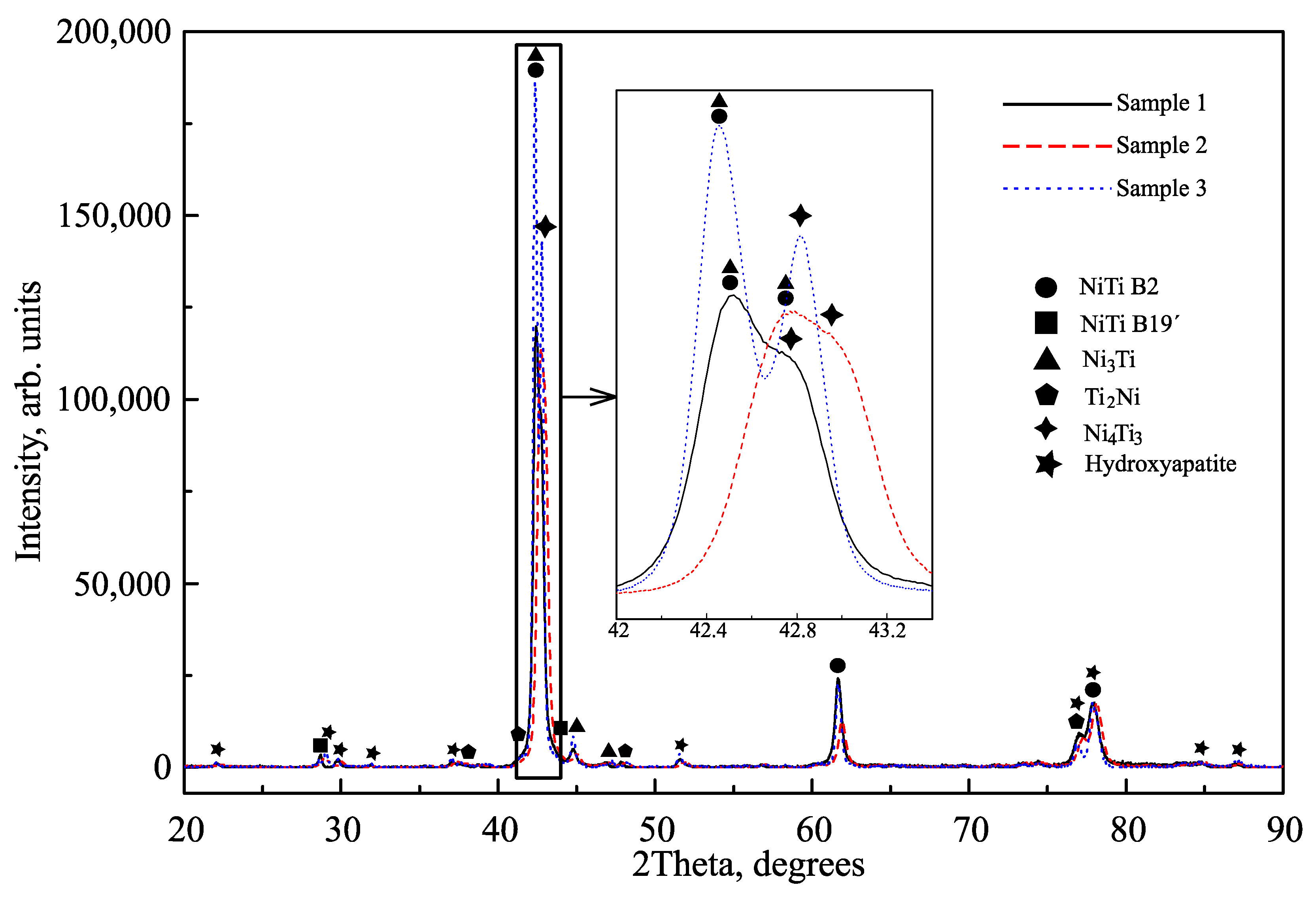
X-ray diffraction patterns were obtained from three NiTi samples coated with hydroxyapatite in Figure 1. Interpretation of X-ray diffraction patterns made it possible to establish that all samples consisted of the TiNi phase in two crystallographic modifications: cubic B2 austenite (cod_1100132) and monoclinic B19’ martensite (cod_9015813). Secondary intermetallic inclusions Ti2Ni (cod_1527848), Ni3Ti (cod_1010452), and Ni4Ti3 (cod_2100704) were also found, which are the result of the technological process of obtaining monolithic alloys. Monoclinic hydroxyapatite (HAp, mp-721624, a = 9.39 Å, b = 6.87 Å, c = 2a, and γ = 120°) was found on the surfaces of all samples. With an increase in the coating deposition time, the intensity of the HAp diffraction reflections increased, indicating a thicker surface layer. In addition to reflections corresponding to crystalline HAp, X-ray diffraction patterns did not reveal reflections related to other calcium phosphates. In hard tissues such as bones and teeth, the crystal structure of hydroxyapatite is hexagonal with lattice parameters a = b = 9.4 Å, c = 6.86 Å, and γ = 120° (mp-41472). Monoclinic HAp is more thermodynamically stable than hexagonal HAp, even at room temperature. However, the main difference between the forms of HAp lies in the orientation of the hydroxyl groups.
A pronounced splitting of the structural reflection was observed in sample 3 at the 42–42.5° diffraction angle range, which was not present in the other two samples in Figure 1. Probably, with an increase in the deposition time, the Ni4Ti3 reflection began to manifest itself more clearly, but it was not possible to establish the reason for this. A slight shift of the high-intensity reflection from the NiTi phase with the B2 austenite structure is worth noting. The shift is associated with a change in the crystal lattice parameters caused by the incorporation of coating atoms into the NiTi bcc structure. Thus, the XRD method shows that, with an increase in the deposition time of the coating, the diffraction reflections from the hkl planes of the HAp become more intense, indicating an increase in the deposited coating thickness.
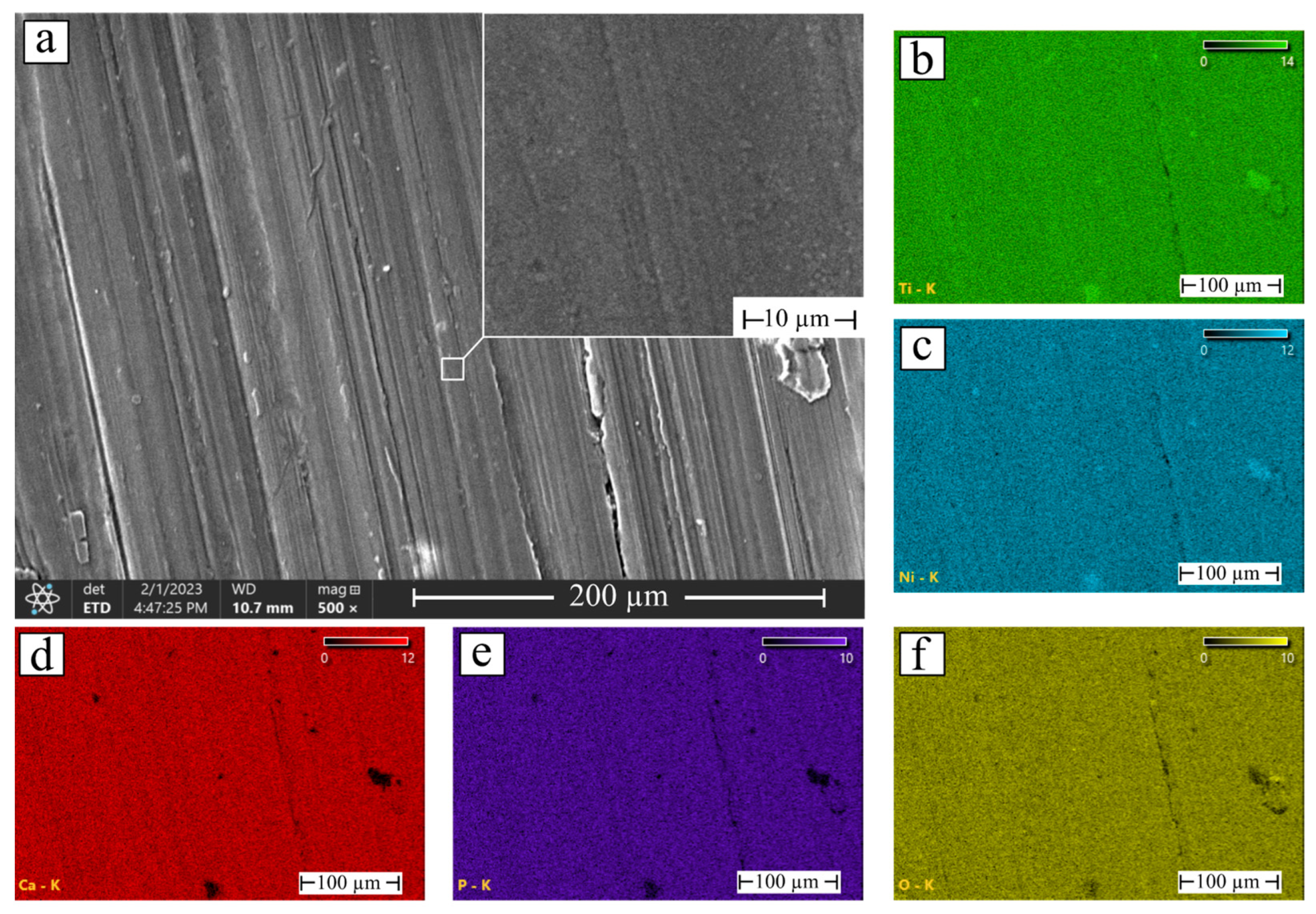
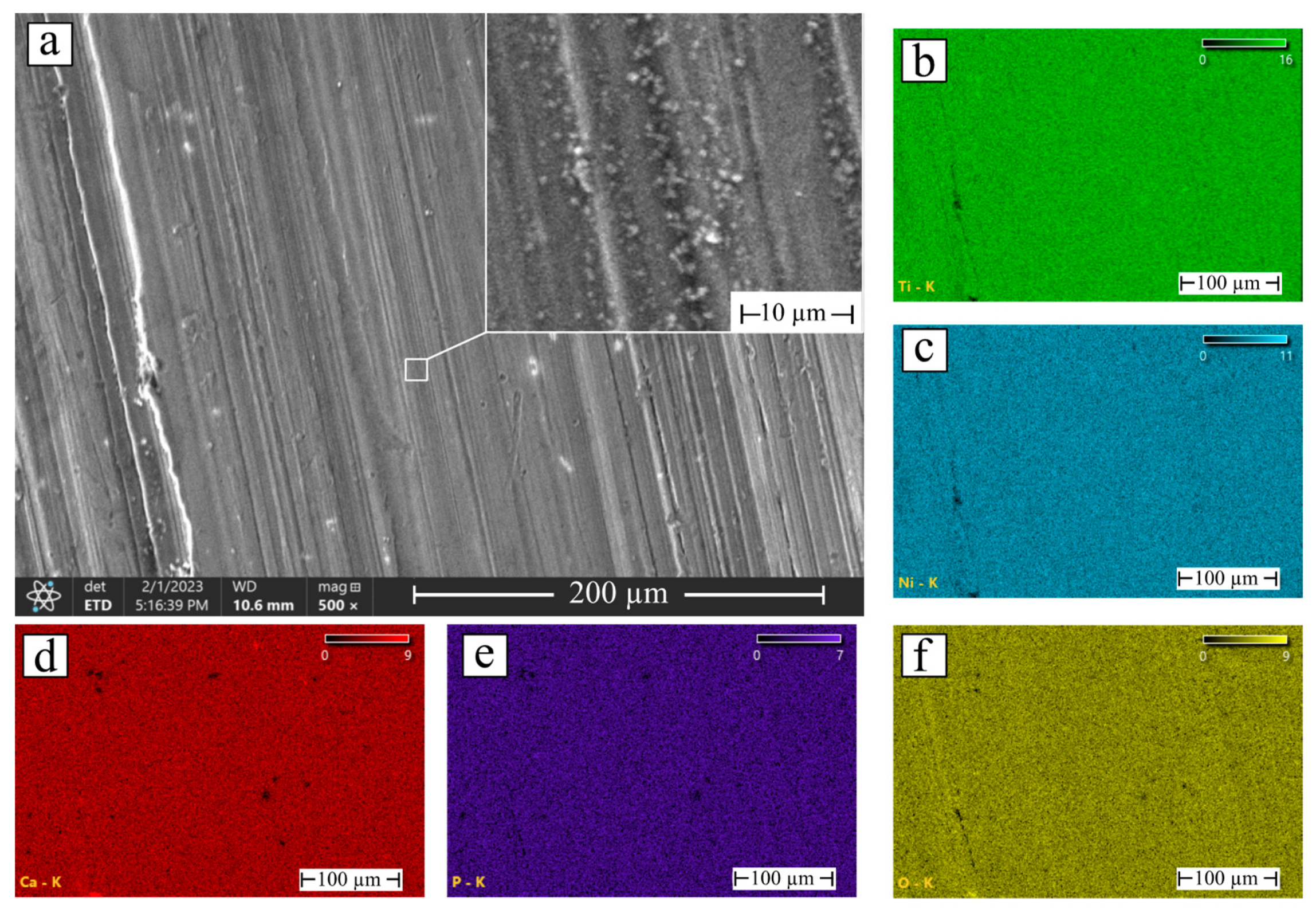
The surface of NiTi alloys coated with HAp was studied using scanning electron microscopy. Samples 1 and 2 had a similar surface morphology in Figure 2 and Figure 3 with small inclusions up to 2 µm in size. Elemental composition analysis showed that the coatings consisted of calcium, phosphorus, and oxygen. Ti and Ni substrate elements were also detected since the spectra registration depth reaches 2 μm. The detected inclusions consisted of the Ti, Ni, and O elements. In terms of size and quantity, these inclusions predominated in sample 1. According to the Ca, P, and O element distribution maps, the coatings were formed unevenly, and a deposition time of 2 h was not enough to obtain a dense HAp layer.
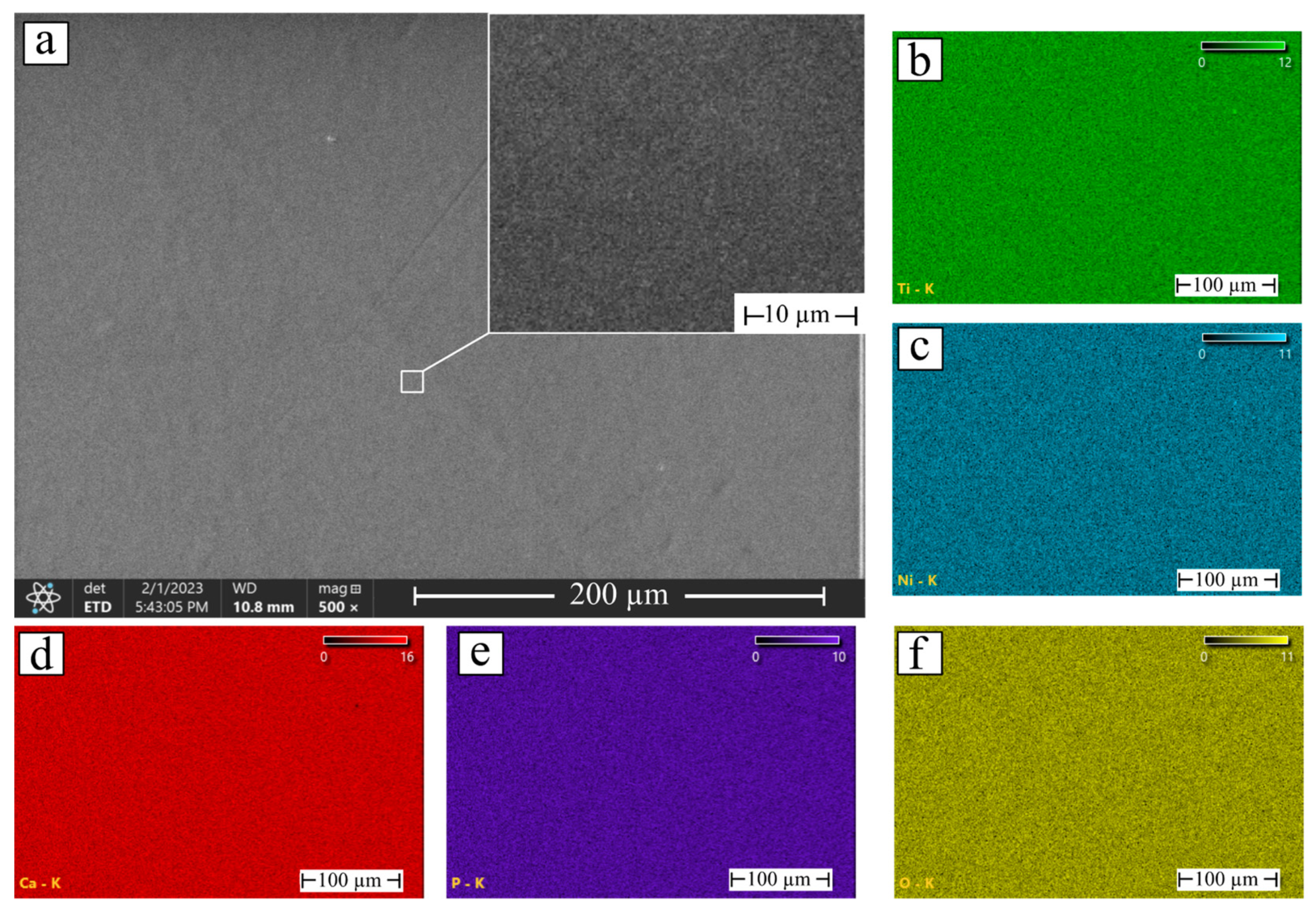
The coating on sample 3 was characterized by a uniform dense surface morphology over the entire area without visible defects, cracks, or chips as seen in Figure 4 in contrast to the coatings on samples 1 and 2.
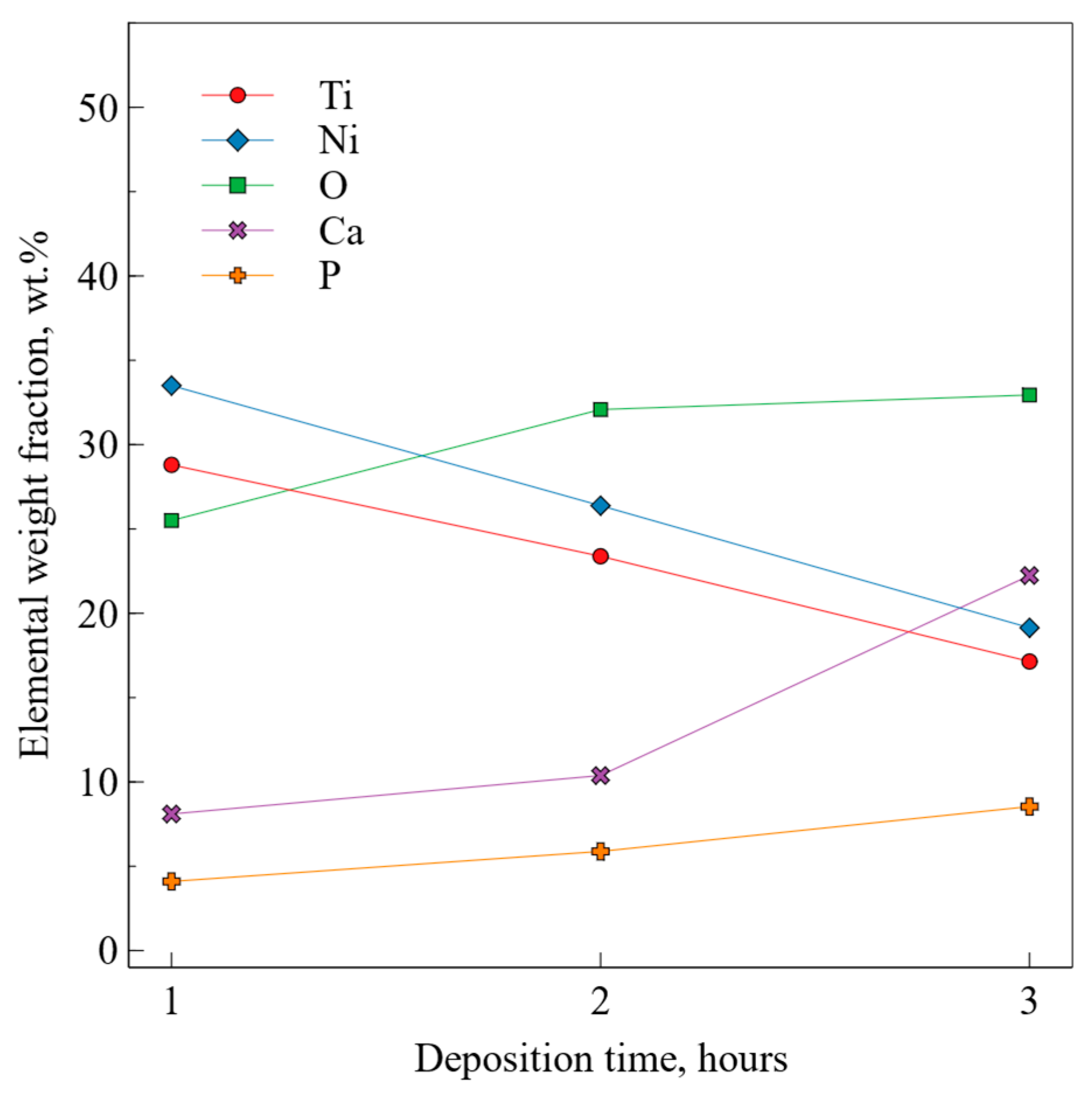
Quantitative EDS analysis showed a decrease in Ti and Ni content and an increase in Ca, P, and O content with deposition time in Figure 5. These data were consistent with the XRD results, according to which the number and intensity of diffraction reflections increased with deposition time. Quantitative EDS analysis of hydroxyapatite-coated NiTi samples also suggested an increase in the coating thickness.
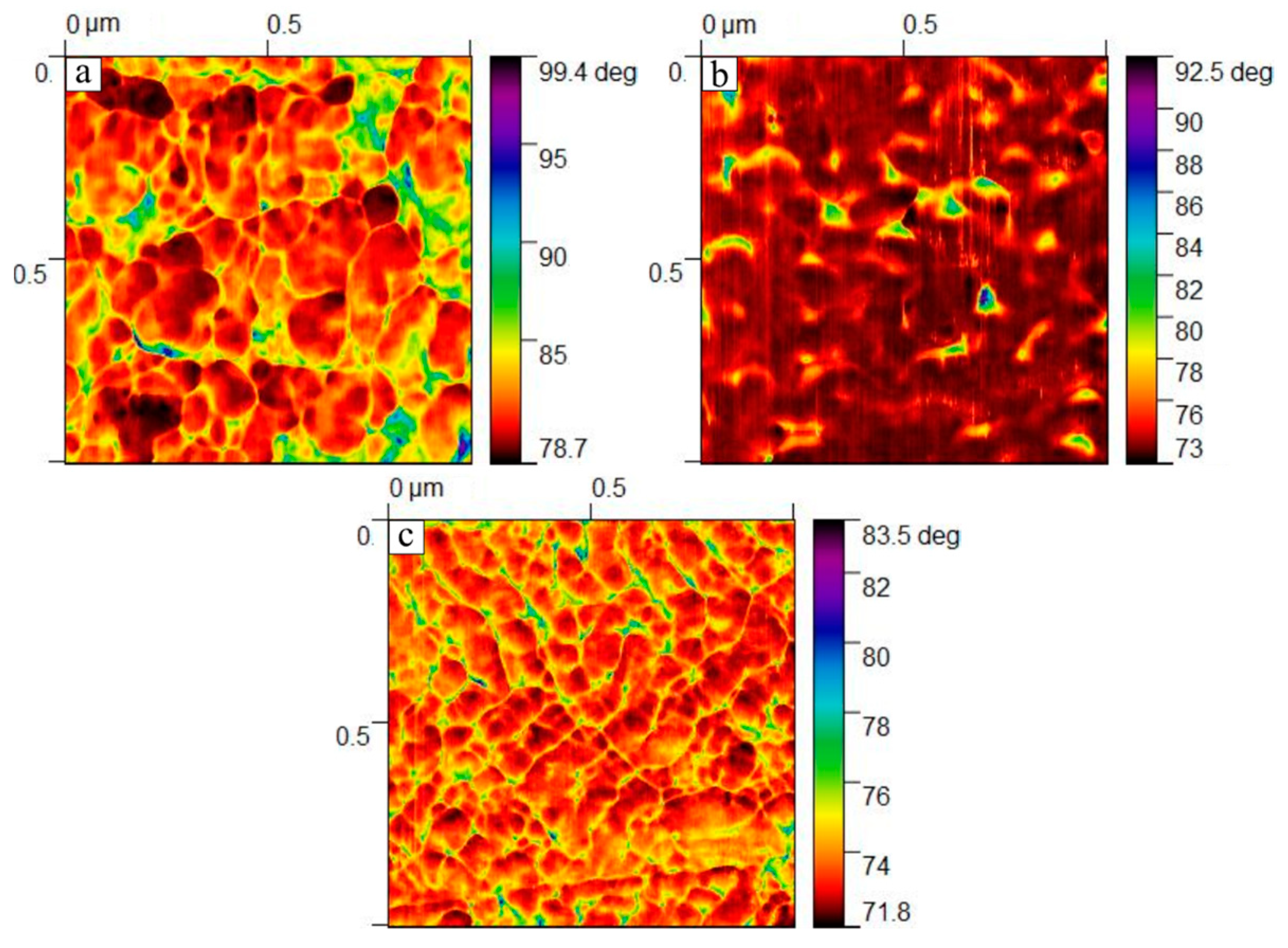
Phase images 1 × 1 µm2 in size were obtained using AFM in Figure 6. Since the survey was carried out in the tapping mode, the tip of the probe touched the surface during oscillations. Because of this, it experienced not only the influence of Coulomb forces, but also adhesive, capillary, and other forces. This caused a phase shift of the oscillations, which made it possible to obtain phase images showing the differences between the areas of the surface. The surface of sample 1 showed large gaps at the grain boundaries, confirming the SEM data of an uneven coating. With an increase in the deposition time, samples 2 and 3 formed a more uniform coating with many small formations of various shapes ranging in size from 0.1 µm to 0.2 µm.
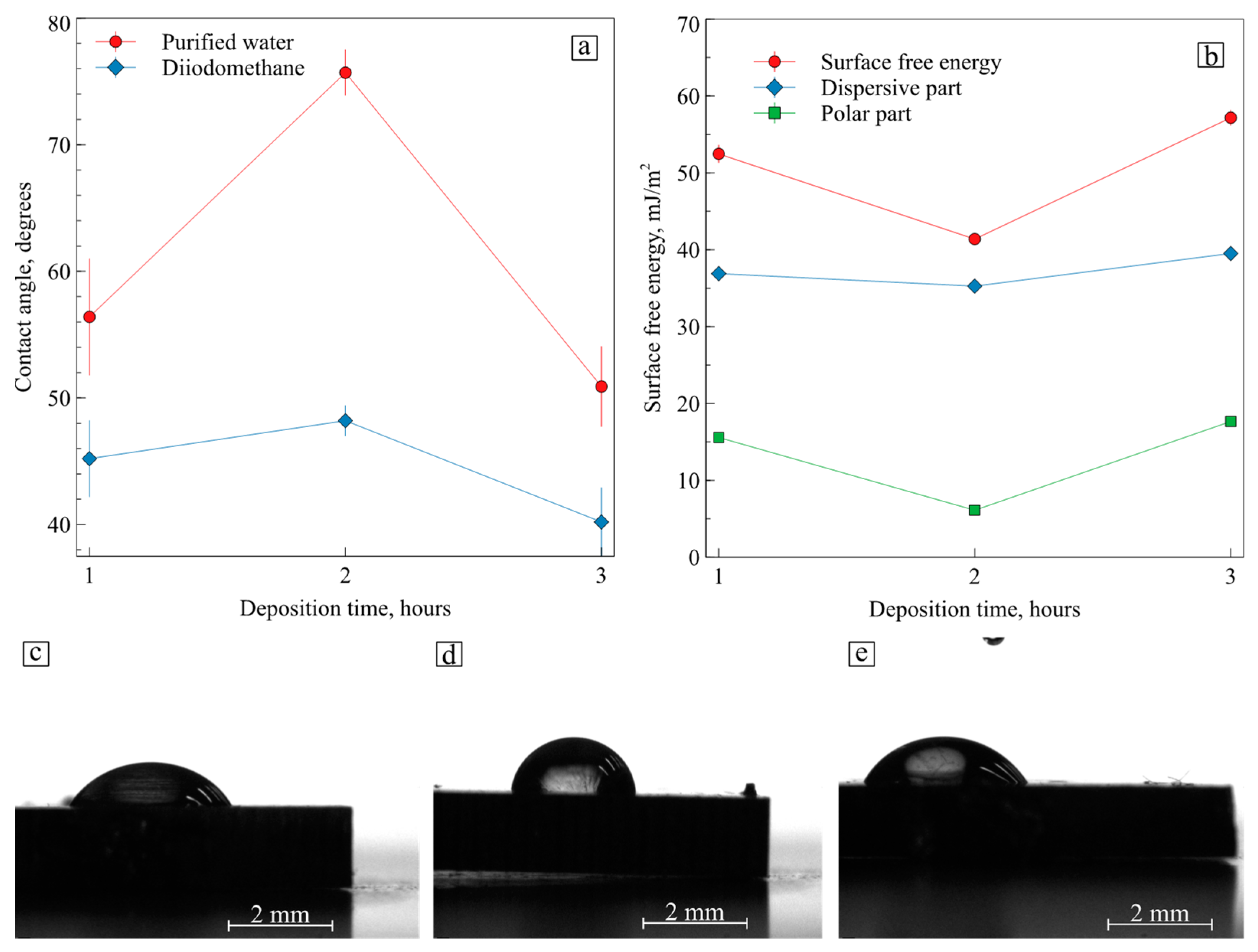
The contact angle was determined using the sessile drop method, and the surface free energy was calculated in Figure 7. Sample 1 exhibited a water contact angle of approximately 56° with a surface free energy of 52 mJ/m2, which predominantly consisted of a dispersive component. An increase in the deposition time to 2 h contributed to the formation of a more hydrophobic HAp coating for sample 2 with a wetting angle of 86°, while the surface energy decreased to 41.39 mJ/m2 due to a significant decrease in the polar energy part to 6.12 mJ/m2. Hydrophobic surfaces are known to exhibit low cell culture attachment efficiency and a long induction period before cells enter the exponential growth phase [20]. Sample 3 was characterized by the most hydrophilic surface of all three coatings with a contact angle of 40.2° and with a maximum surface energy of 57.17 mJ/m2 due to an increase in the polar part to 17.66 mJ/m2.
Considering that the ratio between the dispersive and the polar parts of the surface energy made it possible to predict the adhesion between the two phases, it was concluded that samples 1 and 3 would have the best adhesion during in vitro biocompatibility tests. This is because an increase in surface energy—in particular, an increase in the polar component of the surface energy—has a positive effect on cell adhesion [5]. However, since defects in the coating were found on the surface of sample 1, which could affect the contact angle and surface energy, it made sense to consider only sample 3 for in vitro tests. It should be noted that not only polar groups but also non-polar groups, as well as ligands on the cell surface and protein secretion, are responsible for the behavior of cells on the surface [21], which makes it quite difficult to predict the behavior of cells on artificial materials.
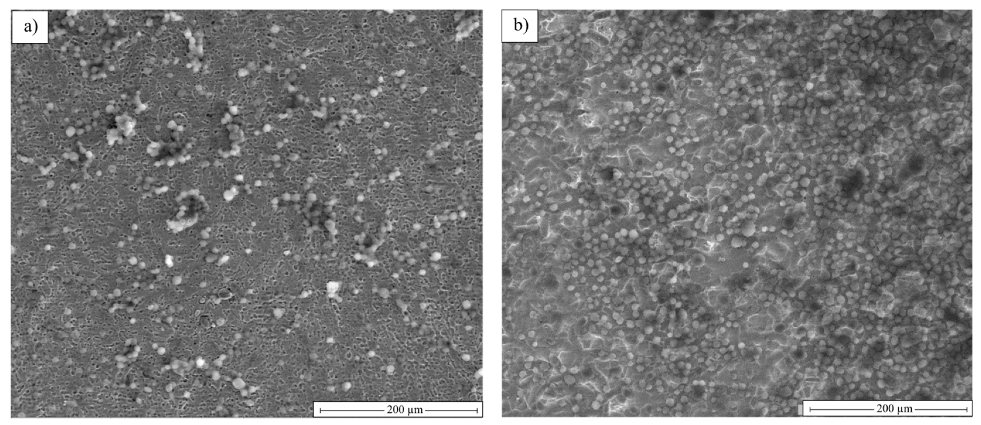
Samples 2 and 3 were chosen for in vitro studies since the coating of sample 1 had pronounced defects. SEM studies after 3-day cultivation of the cells made it possible to establish their normal morphology in Figure 8. The cells spread across the whole surface of sample 2. Some of them formed colonies consisting of several cells, but individual cells can also be seen. After 3 h of deposition, the adhesion of the cells became much better. There were no areas without the cells, so the calcium phosphate coating on sample 3 positively affected cell proliferation.
Despite the in vitro tests, one cannot claim that the increase in deposition time allowed for a boost in the number of viable cells, as some of them could have died. We can only estimate the level of proliferation, which certainly increased after 3 h of deposition. Other researchers have provided the results of in vitro experiments and proved that sputtered hydroxyapatite coatings increase cell viability [22].
4. Conclusions
Three samples with hydroxyapatite coatings were obtained using plasma-assisted RF sputtering for different deposition times of 1, 2, and 3 h. It was established using XRD that a coating of thermodynamically stable monoclinic HAp was formed on all three samples. The NiTi substrate had a mixed structure. The TiNi phase was in the form of two crystallographic modifications of B2 austenite and B19’ martensite, as well as intermetallic Ti2Ni, Ni3Ti, and Ni4Ti3 compounds. The structural studies showed that the densest defect-free coating was formed on sample 3 after 3 h of deposition, and according to EDS data, calcium, and phosphorus were evenly distributed over the surface. Sample 3 had the most hydrophilic surface with a contact angle of 40.2° and showed a significantly increased polar surface energy component of 17.66 mJ/m2 and a high total surface energy of 57.17 mJ/m2. Tests for cytocompatibility in vitro conditions showed that the surface of sample 2 was filled with cells unevenly, while the coating on sample 3 had a positive effect on adhesion and proliferative activity. Based on the obtained results, it can be concluded that a 3 h deposition time is promising for obtaining biocompatible HAp coatings on NiTi.
Author Contributions
Conceptualization, E.S.M., G.A.B. and K.M.D.; methodology, E.S.M.; validation, E.S.M., G.A.B. and K.M.D.; formal analysis, K.M.D.; investigation, G.A.B. and K.M.D.; resources, K.M.D. and I.I.G.; data curation, I.I.G.; writing—original draft preparation, K.M.D.; writing—review and editing, E.S.M., G.A.B. and A.A.V.; visualization, K.M.D.; supervision, E.S.M.; project administration, G.A.B.; funding acquisition, E.S.M. and A.A.V. All authors have read and agreed to the published version of the manuscript.
Funding
This research was supported by the Russian Science Foundation, No. 19-72-10105, https://rscf.ru/project/19-72-10105/ (accessed on 28 March 2023).
Institutional Review Board Statement
Not applicable.
Informed Consent Statement
Not applicable.
Data Availability Statement
The raw/processed data required to reproduce the above findings cannot be shared at this time as the data also forms part of an ongoing study.
Conflicts of Interest
The authors declare no conflict of interest.
References
- Nguyen, T.-T.; Hu, C.-C.; Chou, B.-Y.; Chou, C.-Y.; Lin, G.-Y.; Hu, Y.-C.; Chen, Y.-L.; Hsu, W.-T.; Lin, Z.-S.; Lee, Y.-L.; et al. Evaluating hydrogenated nickel-titanium alloy for orthopedic implant. J. Mater. Res. Technol. 2022, 18, 1115–1123. [Google Scholar] [CrossRef]
- Chen, S.; Zhang, B.; Hu, J.; Zheng, X.; Qin, S.; Li, C.; Wang, S.; Mao, J.; Wang, L. Bioinspired NiTi-reinforced polymeric heart valve exhibiting excellent hemodynamics and reduced stress. Compos. B Eng. 2023, 255, 110615. [Google Scholar] [CrossRef]
- Mareci, D.; Earar, K.; Zetu, I.; Bolat, G.; Crimu, C.; Istrate, B.; Munteanu, C.; Matei, M.N. Comparative Electrochemical Behaviour of Uncoated and Coated NiTi for Dental Orthodontic Wires. Mater. Plast. 2015, 52, 150–153. [Google Scholar]
- Wever, D.J.; Veldhuizen, A.G.; Sanders, M.M.; Schakenraad, J.M.; van Horn, J.R. Cytotoxic, allergic and genotoxic activity of a nickel-titanium alloy. J. Biomater. 1997, 18, 1115–1120. [Google Scholar] [CrossRef] [PubMed]
- Hallab, N.J.; Bundy, K.J.; O’Connor, K.; Moses, R.L.; Jacobs, J.J. Evaluation of metallic and polymeric biomaterial surface energy and surface roughness characteristics for directed cell adhesion. Tissue Eng. 2001, 71, 55–71. [Google Scholar] [CrossRef] [Green Version]
- Mehta, K.; Gupta, K. Fabrication and Processing of Shape Memory Alloys, 1st ed.; Springer International Publishing: Cham, Switzerland, 2019; p. 84. [Google Scholar] [CrossRef]
- Witkowska, J.; Sowińska, A.; Czarnowska, E.; Płociński, T.; Rajchel, B.; Tarnowski, M.; Wierzchoń, T. Structure and properties of composite surface layers produced on TiNi shape memory alloy by a hybrid method. J. Mater. Sci. Mater. Med. 2018, 29, 110–119. [Google Scholar] [CrossRef] [Green Version]
- Marchenko, E.; Baigonakova, G.; Dubovikov, K.; Kokorev, O.; Yasenchuk, Y.; Vorozhtsov, A. In Vitro Bio-Testing Comparative Analysis of NiTi Porous Alloys Modified by Heat Treatment. Metals 2022, 12, 1006. [Google Scholar] [CrossRef]
- Sheykholeslami, S.O.R.; Khalil-Allafi, J.; Fathyunes, L. Preparation, Characterization, and Corrosion Behavior of Calcium Phosphate Coating Electrodeposited on the Modified Nanoporous Surface of NiTi Alloy for Biomedical Applications. Metall. Mater. Trans. A Phys. Metall. Mater. Sci. 2018, 49, 5878–5887. [Google Scholar] [CrossRef]
- Shirdar, M.R.; Sudin, I.; Taheri, M.M.; Keyvanfar, A.; Yusop, M.Z.M.; Kadir, M.R.A. A novel hydroxyapatite composite reinforced with titanium nanotubes coated on Co-Cr-based alloy. Vacuum 2015, 122, 82–89. [Google Scholar] [CrossRef]
- Shanaghi, A.; Mehrjou, B.; Ahmadian, Z.; Souri, A.R.; Chu, P.K. Enhanced corrosion resistance, antibacterial properties, and biocompatibility by hierarchical hydroxyapatite/ciprofloxacin-calcium phosphate coating on nitrided NiTi alloy. Mater. Sci. Eng. C 2021, 118, 111524. [Google Scholar] [CrossRef]
- Etminanfar, M.R.; Khalil-Allafi, J.; Montaseri, A.; Vatankhah-Barenji, R. Endothelialization and the bioactivity of Ca-P coatings of different Ca/P stoichiometry electrodeposited on the Nitinol superelastic alloy. Mater. Sci. Eng. C 2016, 62, 28–35. [Google Scholar] [CrossRef] [Green Version]
- Jue, L.; Chao, L.; Jing, L.; Min, L.; Jian-ming, R. Calcium phosphate deposition on surface of porous and dense TiNi alloys in simulated body fluid. J. Cent. South Univ. 2016, 23, 1–9. [Google Scholar] [CrossRef]
- Horandghadim, N.; Khalil-Allaf, J.; Urgen, M. Influence of tantalum pentoxide secondary phase on surface features and mechanical properties of hydroxyapatite coating on NiTi alloy produced by electrophoretic deposition. Surf. Coat. Technol. 2020, 386, 125458. [Google Scholar] [CrossRef]
- Etminanfar, M.R.; Sheykholeslami, S.O.R.; Khalili, V.; Mahdavi, S. Biocompatibility and drug delivery efficiency of PEG-b-PCL/hydroxyapatite bilayer coatings on Nitinol superelastic alloy. Ceram. Int. 2020, 46, 12711–12717. [Google Scholar] [CrossRef]
- Mehrvarz, A.; Khalil-Allafi, J.; Etminanfar, M.; Mahdavi, S. The study of morphological evolution, biocorrosion resistance, and bioactivity of pulse electrochemically deposited Hydroxyapatite/ZnO composite on NiTi superelastic alloy. Surf. Coat. Technol. 2021, 423, 127628. [Google Scholar] [CrossRef]
- Harun, W.; Asri, R.; Alias, J.; Zulkifli, F.; Kadirgama, K.; Ghani, S.; Shariffuddin, J. A comprehensive review of hydroxyapatite-based coatings adhesion on metallic biomaterials. Ceram. Int. 2018, 44, 1250–1268. [Google Scholar] [CrossRef]
- Schwartz, A.; Kossenko, A.; Zinigrad, M.; Gofer, Y.; Borodianskiy, K.; Sobolev, A. Hydroxyapatite Coating on Ti-6Al-7Nb Alloy by Plasma Electrolytic Oxidation in Salt-Based Electrolyte. Materials 2022, 15, 7374. [Google Scholar] [CrossRef] [PubMed]
- Kima, T.H.; Yeom, G.Y. A Review of Inductively Coupled Plasma-Assisted Magnetron Sputter System. Appl. Sci. Converg. Technol. 2019, 28, 131–138. [Google Scholar] [CrossRef]
- Dowling, D.P.; Miller, I.S.; Ardhaoui, M.; Gallagher, W.M. Effect of Surface Wettability and Topography on the Adhesion of Osteosarcoma Cells on Plasma-modified Polystyrene. J. Biomater. Appl. 2011, 26, 327–347. [Google Scholar] [CrossRef] [PubMed]
- Majhy, B.; Priyadarshini, P.; Sen, A.K. Effect of surface energy and roughness on cell adhesion and growth-facile surface modification for enhanced cell culture. RSC Adv. 2021, 11, 15467–15476. [Google Scholar] [CrossRef]
- Buyuksungur, S.; Huri, P.Y.; Schmidt, J.; Pana, I.; Dinu, M.; Vitelaru, C.; Kiss, A.E.; Tamay, D.G.; Hasirci, V.; Vladescu, A.; et al. In vitro cytotoxicity, corrosion and antibacterial efficiencies of Zn doped hydroxyapatite coated Ti based implant materials. Ceram. Int. 2023, 49, 12570–12584. [Google Scholar] [CrossRef]
Figure 1.
XRD patterns of NiTi samples with hydroxyapatite coatings deposited for 1, 2, and 3 h (samples 1, 2, and 3).
Figure 1.
XRD patterns of NiTi samples with hydroxyapatite coatings deposited for 1, 2, and 3 h (samples 1, 2, and 3).

Figure 2.
(a) SEM image of the NiTi with hydroxyapatite coating deposited for 1 h and elemental maps of: (b) Ti; (c) Ni; (d) Ca; (e) P; and (f) O.
Figure 2.
(a) SEM image of the NiTi with hydroxyapatite coating deposited for 1 h and elemental maps of: (b) Ti; (c) Ni; (d) Ca; (e) P; and (f) O.

Figure 3.
(a) SEM image of the NiTi with hydroxyapatite coating deposited for 2 h and elemental maps of: (b) Ti; (c) Ni; (d) Ca; (e) P; and (f) O.
Figure 3.
(a) SEM image of the NiTi with hydroxyapatite coating deposited for 2 h and elemental maps of: (b) Ti; (c) Ni; (d) Ca; (e) P; and (f) O.

Figure 4.
(a) SEM image of the NiTi with hydroxyapatite coating deposited for 3 h and elemental maps of: (b) Ti; (c) Ni; (d) Ca; (e) P; and (f) O.
Figure 4.
(a) SEM image of the NiTi with hydroxyapatite coating deposited for 3 h and elemental maps of: (b) Ti; (c) Ni; (d) Ca; (e) P; and (f) O.

Figure 5.
Quantitative elemental EDS analysis of NiTi with hydroxyapatite coatings.

Figure 6.
Phase contrast maps obtained using AFM of NiTi with hydroxyapatite coatings deposited for: (a) 1 h; (b) 2 h; and (c) 3 h.
Figure 6.
Phase contrast maps obtained using AFM of NiTi with hydroxyapatite coatings deposited for: (a) 1 h; (b) 2 h; and (c) 3 h.

Figure 7.
(a) Contact angle; (b) surface energy values of NiTi with hydroxyapatite coatings; the purified water drops on hydroxyapatite coatings deposited for: (c) 1 h; (d) 2 h; and (e) 3 h.
Figure 7.
(a) Contact angle; (b) surface energy values of NiTi with hydroxyapatite coatings; the purified water drops on hydroxyapatite coatings deposited for: (c) 1 h; (d) 2 h; and (e) 3 h.

Figure 8.
SEM images of hydroxyapatite coatings deposited for (a) 2 h and (b) 3 h after 72 h culture with MCF-7 cells.
Figure 8.
SEM images of hydroxyapatite coatings deposited for (a) 2 h and (b) 3 h after 72 h culture with MCF-7 cells.

Disclaimer/Publisher’s Note: The statements, opinions and data contained in all publications are solely those of the individual author(s) and contributor(s) and not of MDPI and/or the editor(s). MDPI and/or the editor(s) disclaim responsibility for any injury to people or property resulting from any ideas, methods, instructions or products referred to in the content. |
© 2023 by the authors. Licensee MDPI, Basel, Switzerland. This article is an open access article distributed under the terms and conditions of the Creative Commons Attribution (CC BY) license (https://creativecommons.org/licenses/by/4.0/).
Share and Cite
MDPI and ACS Style
Marchenko, E.S.; Dubovikov, K.M.; Baigonakova, G.A.; Gordienko, I.I.; Volinsky, A.A. Surface Structure and Properties of Hydroxyapatite Coatings on NiTi Substrates. Coatings 2023, 13, 722. https://doi.org/10.3390/coatings13040722
AMA Style
Marchenko ES, Dubovikov KM, Baigonakova GA, Gordienko II, Volinsky AA. Surface Structure and Properties of Hydroxyapatite Coatings on NiTi Substrates. Coatings. 2023; 13(4):722. https://doi.org/10.3390/coatings13040722
Chicago/Turabian StyleMarchenko, Ekaterina S., Kirill M. Dubovikov, Gulsharat A. Baigonakova, Ivan I. Gordienko, and Alex A. Volinsky. 2023. "Surface Structure and Properties of Hydroxyapatite Coatings on NiTi Substrates" Coatings 13, no. 4: 722. https://doi.org/10.3390/coatings13040722
Note that from the first issue of 2016, this journal uses article numbers instead of page numbers. See further details here.