Article

Effect of Ni Coating on Microstructure and Property of Al Alloy/Steel CMT Welding-Brazing Joints

1
School of Materials Science and Engineering, Jiangsu University of Science and Technology, Zhenjiang 212003, China
2
School of Public Utilities, Jiangsu Urban and Rural Construction Vocational College, Changzhou 213003, China
3
Zhengzhou Research Institute of Mechanical Engineering, Zhengzhou 450001, China
*
Author to whom correspondence should be addressed.
Coatings 2023, 13(2), 418; https://doi.org/10.3390/coatings13020418
Submission received: 6 January 2023 / Revised: 2 February 2023 / Accepted: 6 February 2023 / Published: 12 February 2023

Abstract

:
The cold metal transfer (CMT) welding-brazing process was chosen to join Al alloy and Ni-coated steel using AlSi12 as the filler wire. The macrostructure and microstructure of the joints were tested by using an optical microscope (OM), scanning electron microscope (SEM), energy dispersive spectrometry (EDS), and X-ray diffraction (XRD). The tensile properties and corrosion properties of the joints were also tested. The results showed that Ni coating could improve the wettability and spreadability of molten AlSi12 filler metal on the steel surface, resulting in a good appearance for the Al alloy/steel joint. Ni coating could hinder the chemical metallurgical reaction between Al atom and Fe atoms to inhibit the formation of brittle Fe-Al intermetallic compounds (IMCs) and reduce the thickness of the IMCs layer. Meanwhile, the Ni atom reacted with the Fe and Al atoms to form Al3Ni2, (Fe, Ni) Al3 and (Fe, Ni)2Al3, which improved the tensile strength of the joints. All joints with Ni coating cracked near the Al alloy. When the Ni-coating thickness was 5 μm, the tensile strength of the joint reached a maximum of 202.5 MPa. The addition of Ni could also improve the corrosion resistance of the joints. Significantly, when the Ni-coating thickness was 10 μm, most of the Ni coating was still solid, and the interface reaction layer was mainly composed of α-Ni solid solution and some (Fe, Ni)2Al3.

1. Introduction

The “Made in China 2025” development strategy proposes that the manufacturing industry changes from a traditional to an intelligent and green industry. Realizing weight reduction is considered a vital way to achieve this change [1,2]. Al alloys, which have the advantages of light weight, high specific strength, corrosion resistance, and good comprehensive performance, are widely used in aerospace, railway transportation, automobiles, and refrigeration [3,4,5]. They partially replace steel to form Al alloy/steel structures for achieving lightweight structures. Al alloy/steel parts have the characteristics of the lightweight of Al alloy together with the advantages of high strength and low cost of steel. They are widely used in the covering parts and chassis parts of automobiles. Undoubtedly, the Al alloy/steel hybrid body has become the trend of future development in the industry. Therefore, the connection of Al alloy/steel parts has high requirements.
For the joining of Al alloy and steel, some of the difficulties are as followings [6]: Firstly, the thermal expansion coefficients are different, which results in the severe deformation of the joints and thus produce considerable residual stress in the welding process. Secondly, due to their poor metallurgical compatibility, a series of brittle IMCs (i.e., FeAl3, Fe2Al5, FeAl2, FeAl) form, which deteriorates the mechanical properties of the joints. Thirdly, the potential of Al alloy is different from that of steel, and the localized electrochemical corrosion near the steel occurred in a humid atmosphere. At the same time, porosity and defects in the joints would accelerate the process of electrochemical corrosion [7].
In order to prepare composite materials with excellent performance, many studies have been carried out. Farhad Ostovan et al. [8,9,10] believed that Gas Tungsten Arc Welding (GTAW) had the unique advantages due to its easy control of heat input. Qin et al. [11] compared and analyzed the advantages of several welding methods to join Al alloy and steel, such as mechanical connection, solid phase connection, liquid-solid diffusion, brazing, GTAW brazing and so on. They found that laser welding brazing, electron beam welding brazing and arc+laser hybrid welding could achieve high-quality Al alloy/steel joints by controlling the welding heat input. Maryam Roudbari et al. [12] reinforced the Al plates with steel wires by using the method of explosive welding. They determined the optimal parameters through the numerical simulation. The simulation results agreed very well with the experimental data. Then they studied the mechanical properties of aluminum base composite materials [13]. The results showed that the tensile strength of the reinforced composite was 8% higher than that of the unreinforced material. However, the explosive welding was limited by the weather and gave rise to the air pollution.
Our research team studied the joining of Al alloy and steel by using welding-brazing technology. Shao et al. [14] used different Al-Si filler metals to join Al alloy and steel by CMT welding brazing, respectively. They reported that Si element could inhibit the formation of brittle IMCs at the interface reaction layer. Shi et al. [15] showed that TIG welding brazing could control welding heat input precisely. The addition of Zn element could improve the wettability of AlSi5 filler metal and also enhance the corrosion resistance of the joint. Chao et al. [16] studied the effect of Cu coating on the microstructure and properties of the joints by CMT welding brazing. They found that with the increase in Cu-coating thickness, the thickness of the IMCs layer decreased and the corrosion resistance of the Al alloy/steel joint increased. When the Cu-coating thickness was 10 μm, the tensile strength and corrosion resistance of the joints were up to the optimum. Other researchers [17] have reported that Ni coating on the steel surface could change the IMCs composition of joints by laser welding brazing. However, they did not discuss the formation mechanism of IMCs compounds in detail, nor did they study the corrosion resistance of the Al/steel joints.
Therefore, in this paper, different thicknesses of Ni layer were designed to be coated on steel surfaces. The CMT welding-brazing process of Al alloy/steel was conducted using AlSi12 as the filler wire. The effects of different Ni-coating on the macrostructure, microstructure, tensile strength, and corrosion resistance of the joints were studied. We focused on exploring the action mechanism of Ni coating on the interface reaction layer of joints.

2. Experimental Materials and Methods

2.1. Experimental Materials

The purchased 6082 Al alloy and Q235B steel with dimensions of 150 mm × 100 mm × 2 mm were used as the base metals. AlSi12 flux-cored wire with a diameter of 1.6 mm was used as the filler material, and it was composed of AlSi12 wire and NOCLOCK flux. The chemical composition and tensile properties of the above materials are listed in Table 1.

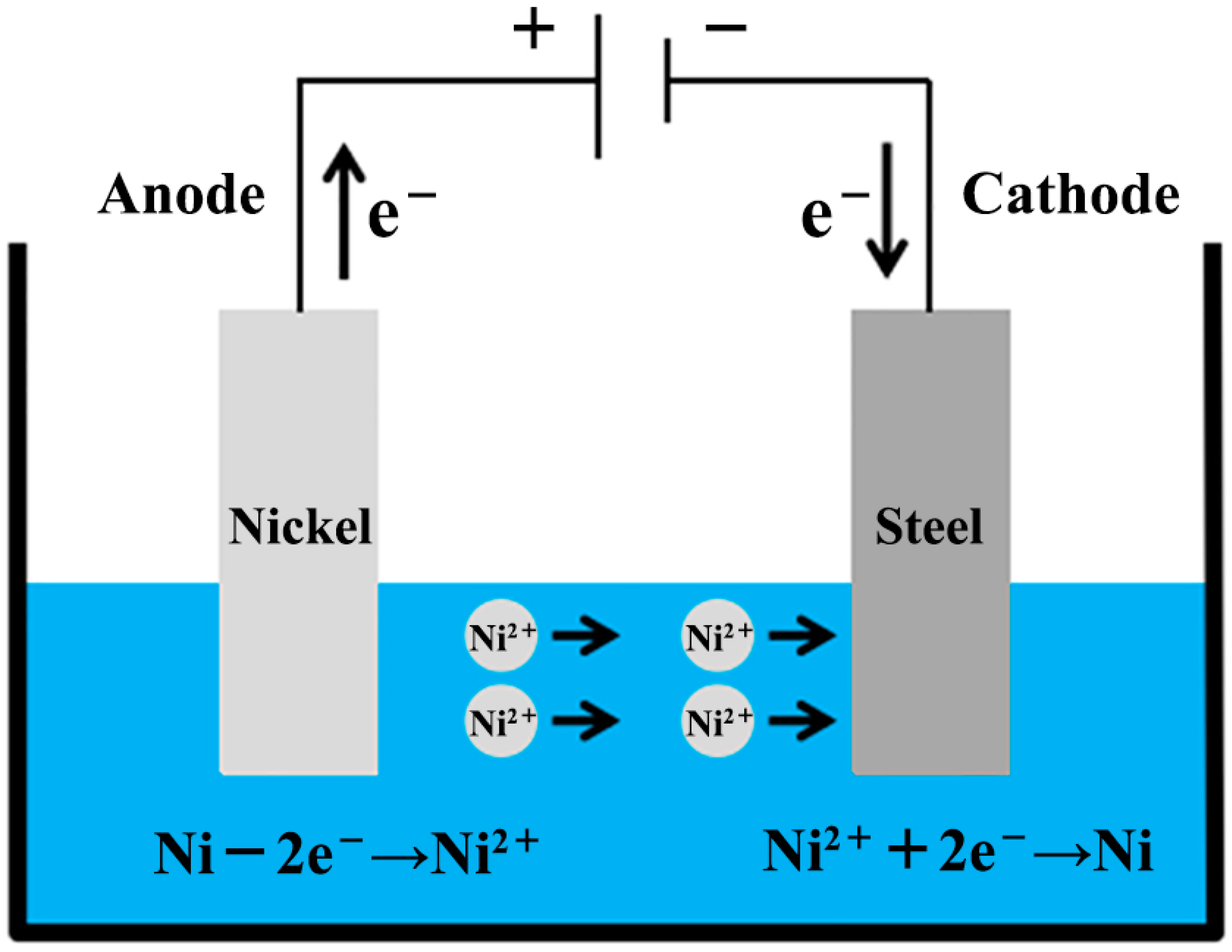
2.2. Coating Process of Ni on the Steel Surface

Ni layers that ranged from 0 μm and 10 μm were coated on the surface of Q235B steel by the electroplating process. At least five samples were prepared and tested for each Ni-coating thickness. Before electroplating, all steel plates were polished with sandpaper to remove burrs. Subsequently, the steel plates were immersed into an alkaline solution at 80 °C for 20 min to remove oil stains. The composition of the alkaline solution was 30 g/L NaOH, 35 g/L NaCO3, 20 g/L NaPO4, and 7.5 g/L OP-10. Then, they were immersed in the acid solution for 2 minutes, which was composed of 5% H2SO4, 15% HCl, and 80% distilled water. After chemical cleaning, the steel plates were washed in the acetone solution with an ultrasonic cleaner to be electroplated. The electroplating solution containing 200 g/L NiSO4, 30 g/L NiCl2, 30 g/L H3BO3, 0.1 g/L C12H25NaSO3 and 0.5 g/L saccharin was prepared and stirred for 30 min. Finally, the treated steel plates were placed into the electroplating solution. During the electroplating process, the nickel plate was used as the anode, while the steel plate was used as the cathode. The process parameters of electroplating were a pH of 4, a temperature of 50 °C, and a current density of 1.5 A/min. The schematic diagram of the electroplating process is shown in Figure 1.

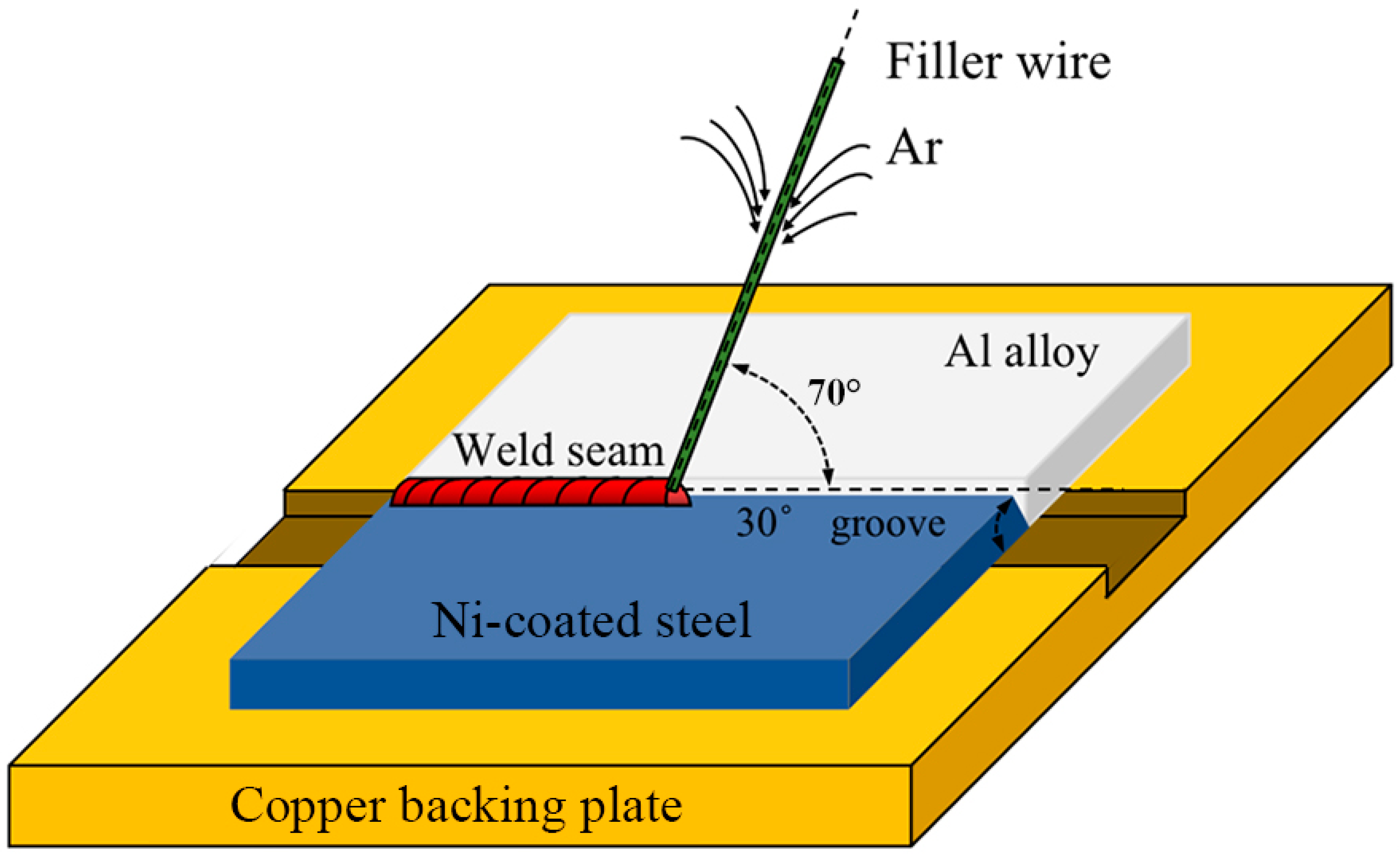
2.3. CMT Welding-Brazing Process to Join Al Alloy/Steel

A CMT5000i welding machine (Fronius company) was used to join Al alloy and Ni-coated steel with the AlSi12 filler wire. Before CMT welding brazing, we cleaned the base metals with the acetone. The Al alloy plates had no groove while the steel plates were equipped with a single V-shaped groove of 30°. The root gap was 0.1 mm for assembly, and we used the copper backing to solidify the welding joint. The inclination angle of the torch was set to 70° and the distance from the tip of the welding wire to the workpiece was 2 mm. The welding process was protected by Argon gas with 99.99% purity. The schematic diagram of the CMT welding-brazing process is illustrated in Figure 2. Its detailed parameters are listed in Table 2.

2.4. Analysis of Microstructure and Tensile Properties of Al Alloy/Steel Joints

After CMT welding brazing, samples for the investigation of microstructure and tensile properties were prepared. All the microstructure analysis samples were mechanically ground with sandpaper and polished with diamond suspension, and then etched by Keller’s reagent for 10–15 s. The macrostructure was observed by a ZEISS optical microscope (OM, Oberkochen, Germany). The microstructure was analyzed by a JSM-6480 scanning electron microscope (SEM, JEOL, Tokyo, Japan), and the element distribution was identified by energy dispersive spectroscopy (EDS). We stripped the Al alloy/steel joint along the side of the steel, and the phase composition of the interface reaction layer and fusion zone were confirmed by an XRD-6000 X-ray diffractometer instrument (XRD, Shimadzu, Kyoto, Japan) with a scanning angle (2θ) ranging from 10° to 90° and a scanning speed of 3 °/min.
According to GB/T 2651-2008 standard, the tensile properties of the joints were tested on an ETM605D mechanical tester at a constant rate of 1 mm/min. The fracture surfaces were observed by SEM.

2.5. Electrochemical Corrosion Measurements of Al Alloy/Steel Joints

An Electrochemical Workstation (No. EGM283) was used to carry out the electrochemical experiments in a 3.5 wt. % NaCl solution. We used a saturated calomel electrode (SCE) as a reference electrode, a platinum plate as an auxiliary electrode, and the Al alloy/steel joint as the working electrode. The specimens including Al alloy, steel, and the Al alloy/steel joint with dimensions of 10 mm × 10 mm × 2 mm were prepared. The potentiodynamic polarization curves were recorded with a scanning rate of 2 mV/s and a scanning range starting at −1 V up to 1.5 V.

3. Results and Discussions

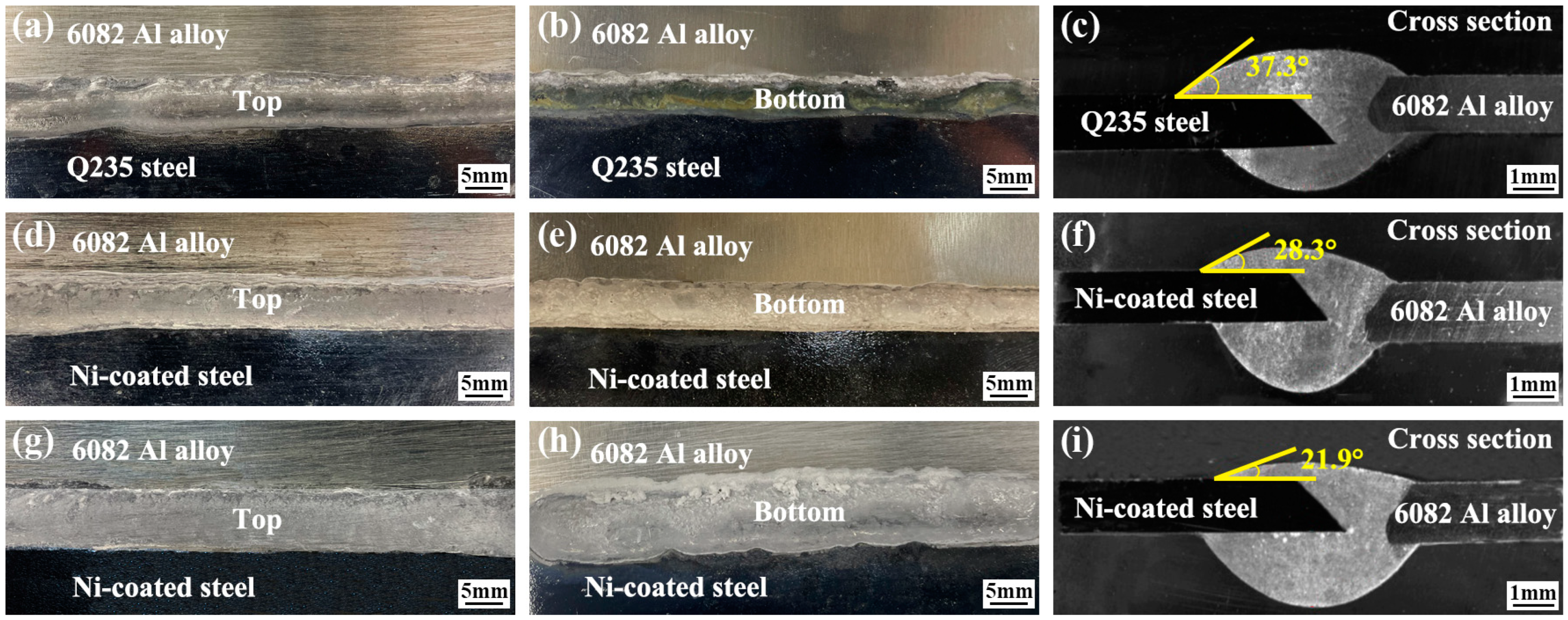
3.1. Effect of Ni Coating on Macrostructure of Al Alloy/Steel Joints

Figure 3 shows the weld seam appearance and cross-section appearance of Al alloy/steel joints with different thicknesses of Ni coating. For Al alloy/steel joints without a Ni coating, the top weld seam shape (see Figure 3a) and the bottom weld seam shape (see Figure 3b) were not continuous and not smooth. When the Ni-coating thickness was 5 µm and 10 µm, the shape of the top weld seam (see Figure 3d,g, respectively) and the bottom weld seam (see Figure 3e,h, respectively) appeared better and smoother.
Seen from the cross-section appearance of the joints, Ni coating has a significant influence on the wettability and spreading of AlSi12 filler metal on the steel surface. For Figure 3c,f,i, the wetting angle of molten AlSi12 filler metal on the steel surface decreased from 37.3° to 28.3° and then 21.9°. Generally, the smaller the wetting angle, the better the wettability. Thus, the results implied that the addition of Ni could improve the wettability and spreadability of molten Al-Si metal on the steel surface. Yang et al. [18] had reported that Ni could reduce the melting point of Ag-based filler metal and improve its wettability. Sun et al. [19] found Ni coating on the surface of Al2O3 particles could improve the wettability of Al2O3/Al-10Si composites. These results are consistent with our research results.

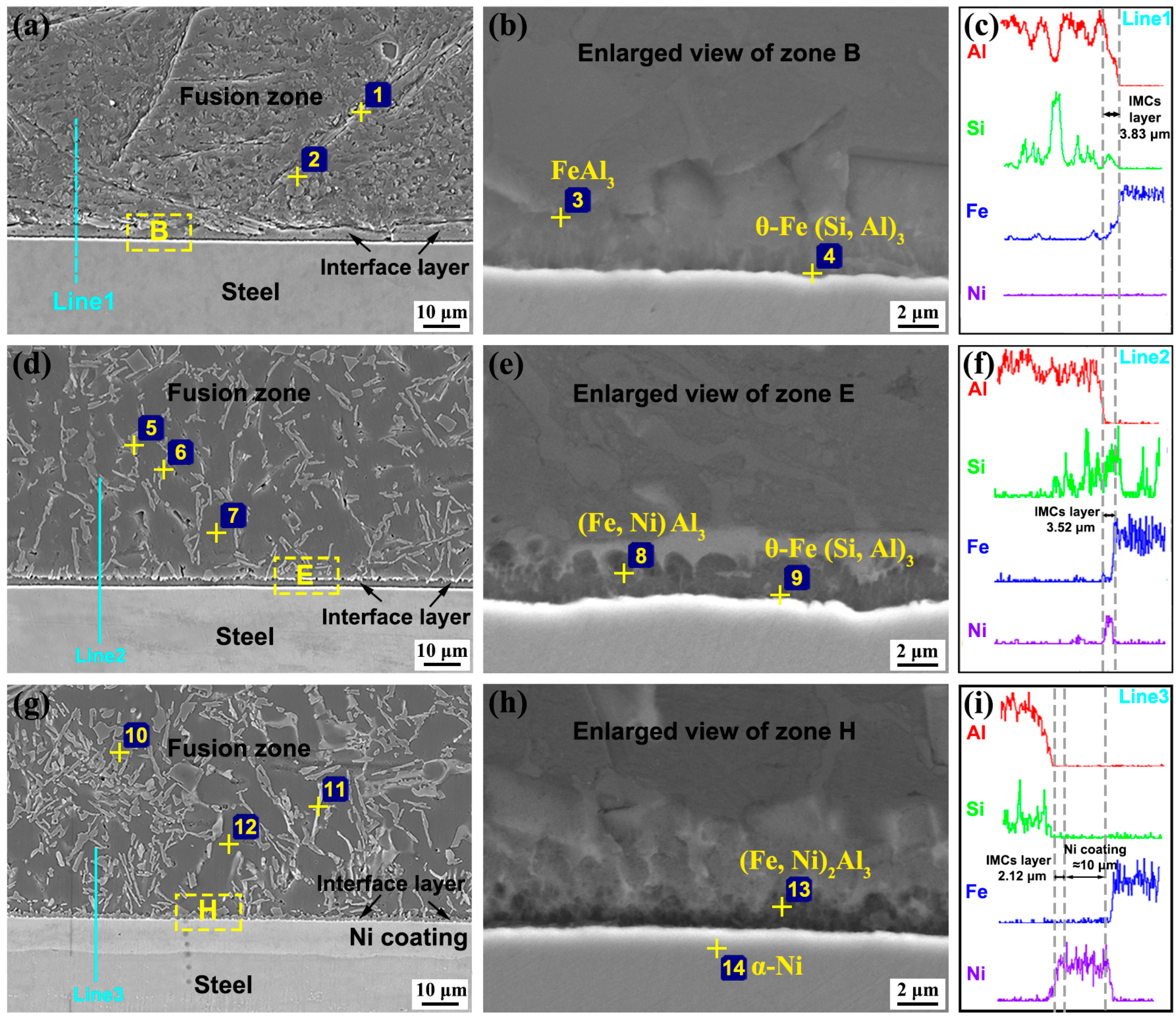
3.2. Influence of Ni Coating on Microstructure of Al Alloy/Steel Joints

In the process of CMT welding brazing, part of the Al alloy base metal together with AlSi12 filler metal preferred to melt under the action of arc heat due to their low melting point (below 660℃), and the fusion zone formed at the side of Al alloy base metal. Then, the molten Al alloy metal wet and spread on the steel surface, which was still solid because of its high melting point (above 1500℃), so the brazing interface reaction zone formed at the side of the steel base metal [20,21]. The fusion zone and brazing interface reaction zone were analyzed by SEM with EDS point and line scanning. The results are shown in Figure 4 and Table 3.
Figure 4a exhibits SEM images of the Al alloy/steel joint without Ni coating. The fusion zone near the Al alloy is composed of needle-like compounds and granular-shaped compounds. Figure 4b shows the enlarged view of zone B in Figure 4a. The brazing interface reaction layer at the steel side is composed of dark gray compounds. Points 1-4 were analyzed by EDS point scanning and the results were listed in Table 2. The interface reaction layer was analyzed by EDS line scanning as shown in Figure 4c. From Figure 4c, the thickness of the IMCs layer was about 3.83 μm. The content of Al element decreased, whereas the content of Fe element increased along the path from the fusion zone to the brazing interface reaction zone. According to the EDS points analysis results and Al-Fe-Si ternary alloy phase diagram, in the fusion zone, the thin needle-like phase (point 1) was a τ5-Al7.2Fe1.8Si and the dark gray phase (point 2) was an α-Al solid solution. Correspondingly, the interface reaction layer consisted of FeAl3 (point 3) formed near the fusion zone and θ-Fe (Si, Al)3 (point 4) formed at the steel side.
Figure 4d shows the microstructure of the joint with 5 μm Ni coating. Figure 4e shows the enlarged view of zone E in Figure 4d. As can be observed, a large number of thin needle-like phases are distributed uniformly in the fusion zone, and the thickness of the IMCs layer decreased to 3.52 μm. Figure 4f shows that the Ni content increases at the interface reaction layer, and Ni element diffuses into the fusion zone. Therefore, in the fusion zone, Al atoms react with the Ni atoms to form Al3Ni2 (point 5) and the thin needle-like phase changed from τ5-Al7.2Fe1.8Si into τ5-Al7.2(Fe, Ni)1.8Si (point 6). The α-Al solid solution (point 7) also contained Ni element. Meanwhile, Ni atoms replace some Fe atoms and then react with Al atoms to form (Fe, Ni) Al3 (point 8) at the interface reaction layer. The gray compound (point 9) was still θ-Fe (Si, Al)3.
When the Ni-coating thickness was 10 μm, the fusion zone contained some small block-shaped tissue, some white dendritical tissue, and a dark-grey matrix. Significantly, the thickness of the interface reaction layer was 12.12 μm, comsisting of about 10 μm Ni coating and 2.12 μm IMCs layer, as shown in Figure 4g,h. Based on the results listed in Table 2, the small block-shaped tissue (point 10) was determined to be Al3Ni2, the white dendritical tissue (point 11) was τ5-Al7.2(Fe, Ni)1.8Si, and the dark-grey matrix (point 12) was α-Al solid solution. The interface reaction layer was composed of (Fe, Ni)2Al3 (point 13) near the fusion zone and α-Ni solid solution (point 14). Figure 4i exhibits the elements distribution of A, Si, Fe, and Ni between the Al alloy and steel. Ni element was mainly concentrated in the interface layer. Meanwhile, a small amount of Al and Si elements in the fusion zone passed through the Ni coating to the steel side, and a few Fe elements arrived at the side of the fusion zone. Most of the Ni coating was still solid, so it hindered the diffusion between Al element and Fe element. Hence, the interface reaction layer was mainly composed of α-Ni solid solution, and some (Fe, Ni)2Al3 compound formed.
To confirm the phase composition, the Al alloy/steel joint was stripped along the side of the steel, and then the XRD analysis of the fusion zone and the interface reaction zone were performed. The results are shown in Figure 5. For the joint without Ni coating, compounds of α-Al solid solution and τ5-Al7.2Fe1.8Si appeared. When the thickness of the Ni coating was 10 μm, the Al3Ni2 compound and the α-Ni solid solution formed in the joints. Some other phases were hard to be determined.
Based on the above investigations, using AlSi12 filler metal to join Al alloy and steel by CMT technology, the joint was mainly composed of α-Al solid solution and τ5-Al7.2Fe1.8Si in the fusion zone, and FeAl3 together with θ-Fe (Si, Al)3 in the interface reaction zone. After coating 5 μm Ni on the steel surface, Ni participated in the metallurgical reaction, and reacted with Al, Fe, and Si elements to form some new phases of τ5-Al7.2(Fe, Ni)1.8Si and Al3Ni2 in the fusion zone. Meanwhile, (Fe, Ni) Al3 replaced FeAl3 in the interface reaction zone. It can be predicted that the change in microstructure composition will improve the mechanical properties of the joints. When the Ni-coating thickness increased to 10 μm, most of the Ni coating did not melt, so the diffusion between Al element and Fe element was blocked. Interestingly, the FeAl3 phase disappeared, and a new phase of (Fe, Ni)2Al3 appeared in the IMCs layer near the Al alloy. The interface reaction zone was mainly composed of α-Ni solid solution. Hence, the mechanical properties of the joint will not be poor.

3.3. Action Mechanism of Ni Coating in Interface Reaction Layer

Generally, ΔG0 is a criterion to predict the spontaneity of a chemical reaction. When the value of ΔG0 is negative, the chemical reaction occurs easily. Moreover, compounds with the lowest ΔG0 are most likely to be formed.
Based on thermodynamic data of Al-Fe compounds [22,23], the functions of several compounds are calculated as followings:
Δ G FeAl 3 0 = 142770 + 50.58 T
Δ G Al Fe 1.8 7.2 Si 0 = 295355 + 94.59 T
Δ G Fe ( Al , Si ) 0 = 142770.0 + 50.8 T
where T represents temperature. During CMT welding brazing, the temperature ranges from 900 K to 1300 K, and the result is Δ G Al Fe 1.8 7.2 Si 0 < Δ G 0   FeAl 3 , which indicates that τ5-Al7.2Fe1.8Si preferentially forms when Al, Fe and Si atoms interact at the interface of the Al alloy and steel.
Figure 6 shows the schematic diagram of the interface reaction layer growth mechanism of an Al alloy/Steel joint with Ni coating by CMT technology. At the initial stage, as shown in Figure 6a, under the action of a pulsed arc, AlSi12 filler metal and a small amount of Al alloy base metal start to melt, while Ni coating remains semi-solid. At this time, Fe and Al atoms cannot form compounds because the Ni coating acts as a barrier layer. However, with the melting of the Ni coating under the action of arc heat, Fe atoms in the steel passed through Ni coating to react with Al and Si atoms, which come from the AlSi12 filler metal and Al alloy base metal, and then τ5-Al7.2Fe1.8Si formed preferentially. Subsequently, FeAl3 also formed as shown in Figure 6b.
Generally, the possible compounds between Al and Ni can be calculated by the following formulas:
Δ G Al Ni 2 3 0 = 71545.2 + 13.7 T
Δ G Al Ni 3 0 = 48483.8 + 12.7 T
Based on formulas (4) and (5), Al3Ni2 is easier to generate. When the Ni coating starts to melt, Al3Ni2 had already appeared in the weld seam zone according to the above microstructure analysis. Fe element is a relative of Ni, so Fe atoms can occupy the positions of Ni atoms to form (Fe, Ni)2Al3, (Fe, Ni) Al3 and τ5-Al7.2(Fe, Ni)1.8Si as a result of their similar electronic structures [24]. Therefore, (Fe, Ni)2Al3, (Fe, Ni) Al3, τ5-Al7.2Fe1.8Si, and τ5-Al7.2(Fe, Ni)1.8Si formed in the interface reaction layer, as shown in Figure 6c.
With the wetting and spreading of molten liquid filler metal on the steel surface, Fe atoms reacts with τ5-Al7.2Fe1.8Si as follows:
Fe + τ5-Al7.2Fe1.8Si = θ-Fe (Al,Si)3
Finally, the interface reaction layer consists of τ5-Al7.2Fe1.8Si and τ5-Al7.2(Fe, Ni)1.8Si in the weld seam zone together with θ-Fe (Al, Si)3 and (Fe, Ni)2Al3 at the steel side, as shown in Figure 6d.

3.4. Effect of Ni Coating on Tensile Properties of Al Alloy/Steel Joints

Figure 7 shows the fracture location and tensile strength of joints. For the joint without Ni, it cracked at the brazing interface reaction layer, as shown in Figure 7a. When the Ni-coating thickness was 5 μm and 10 μm, the fracture mode was located in the fusion zone at the Al alloy side, as shown in Figure 7b,c, respectively. With the increase in Ni-coating thickness from 0 μm to 10 μm, the tensile strength first increased and then decreased, and the tensile fracture displacement gradually increased. When the Ni-coating thickness was 5 μm, the tensile strength value reached the maximum of 202.5 Mpa, as shown in Figure 7d. Figure 7e indicates that the addition of Ni coating improves the plastic toughness of the joints.
For the joint without Ni coating, FeAl3 formed in the interface reaction layer. The brittle FeAl3 tended to become the source of crack propagation, which resulted in the weakness of the joint during the tensile process. Therefore, the joint cracked at the interface reaction layer. For the joint with Ni coating, the Ni coating melted to occupy the position of the Fe atoms and then generated (Fe, Ni) Al3, (Fe, Ni)2Al3 and τ5-Al7.2(Fe, Ni)1.8Si under the heat action of the arc. The tensile strength of the interface reaction layer was improved as a result of adding Ni into Fe-Al-Si compounds [25,26]. Moreover, when the thickness of the Ni coating was 10 μm, it was too heavy to melt and hindered the diffusion of Fe atoms and Al atoms to avoid the generation of the brittle Fe-Al IMCs and prompt the formation of Ni solid solution. Thus, the tensile strength of the interface reaction layer was high, and the joint cracked at the Al alloy side.
The fracture morphologies of the joints were observed by SEM and are shown in Figure 8. In Figure 8a, tearing ridges and cleavage steps were observed in the fracture surface, which exhibited the brittle fracture mode. Based on the EDS result for point 15, the brittle IMC in the fracture surface was FeAl3, which easily became a source of crack propagation and promoted the crack growth, so the corresponding tensile strength of the joint was the lowest. In Figure 8b,c, a large number of dimples were found in the fracture surface, and they showed a typical ductile fracture mode. In addition, the dimples in the fracture with 5 μm Ni coating were more uniform and finer than that with 10 μm Ni coating. The tensile strength of the former joint reached up to the maximum.

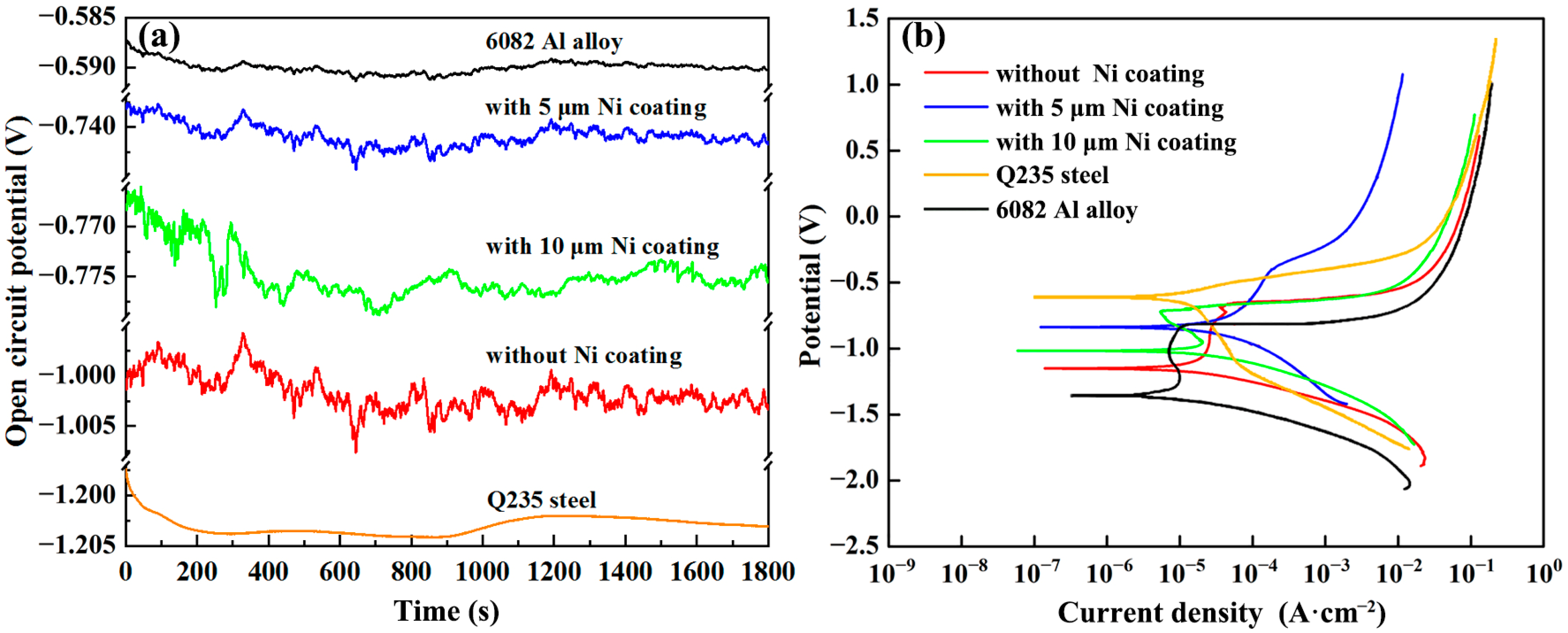
3.5. Effect of Ni Coating on Corrosion Resistance of Al Alloy/Steel Joints

The potentiodynamic polarization curves of joints were measured to investigate the corrosion resistance and the results are shown in Figure 9. Figure 9a shows the variation curve of open-circuit potential with time. When the open circuit potential stabilized, the polarization curves were recorded. As can be seen in Figure 9b, all the curves of joints showed an obvious passivation area, and this indicated the passive film on the surface of joints formed spontaneously to delay their corrosion, but their potential range of the passivation area was different. In order to obtain the related data about the corrosion potential (Ecorr) and the self-corrosion current density (Icorr), CView software was used to fit the curves, and the fitting results are listed in Table 4.
As seen from Figure 9 and Table 4, the Ecorr of the Al alloy plate was the highest, that of the steel plate was the lowest, and that of the joint was between them. Nevertheless, their corrosion current was in reverse order. Meanwhile, compared with the joints without Ni coating and with Ni coating, the Ecorr of the joint with Ni coating was higher while the Icorr of the joint with Ni coating was smaller. Some studies [27] have shown that Ecorr reflects the corrosion tendency of materials, and Icorr reflects the corrosion rate of materials. The greater Ecorr and the smaller Icorr, the better the corrosion resistance of materials.
For the Al alloy/steel joints, galvanic corrosion occurred between the weld seam zone and the steel. The steel with a low corrosion potential can protect the weld seam from corrosion. It was also found that the IMCs layer can accelerate the corrosion of the joint. After adding Ni into the joint, the corrosion resistance of the joint was improved. One reason was that Ni coating hindered the diffusion reaction between Al and Fe, which resulted in a reduction in IMCs thickness. The other reason was that Ni atoms reacted with Al to form Ni2Al3 and replaced Fe atoms to form (Fe, Ni)2Al3, and these compounds improve the corrosion resistance of the joints [28,29,30].

4. Conclusions

In this paper, a CMT welding-brazing process was conducted to join Al alloy and the steel under different Ni coatings by using AlSi12 as a filler wire. The effects of Ni coating on macrostructure, microstructure, tensile properties, and corrosion resistance of the joints were investigated. The main conclusions can be summarized as follows:
(1)
Ni coating can improve the wettability and spreadability of molten AlSi12 filler metal on the steel surface to obtain a good appearance of Al alloy/Steel joints.
(2)
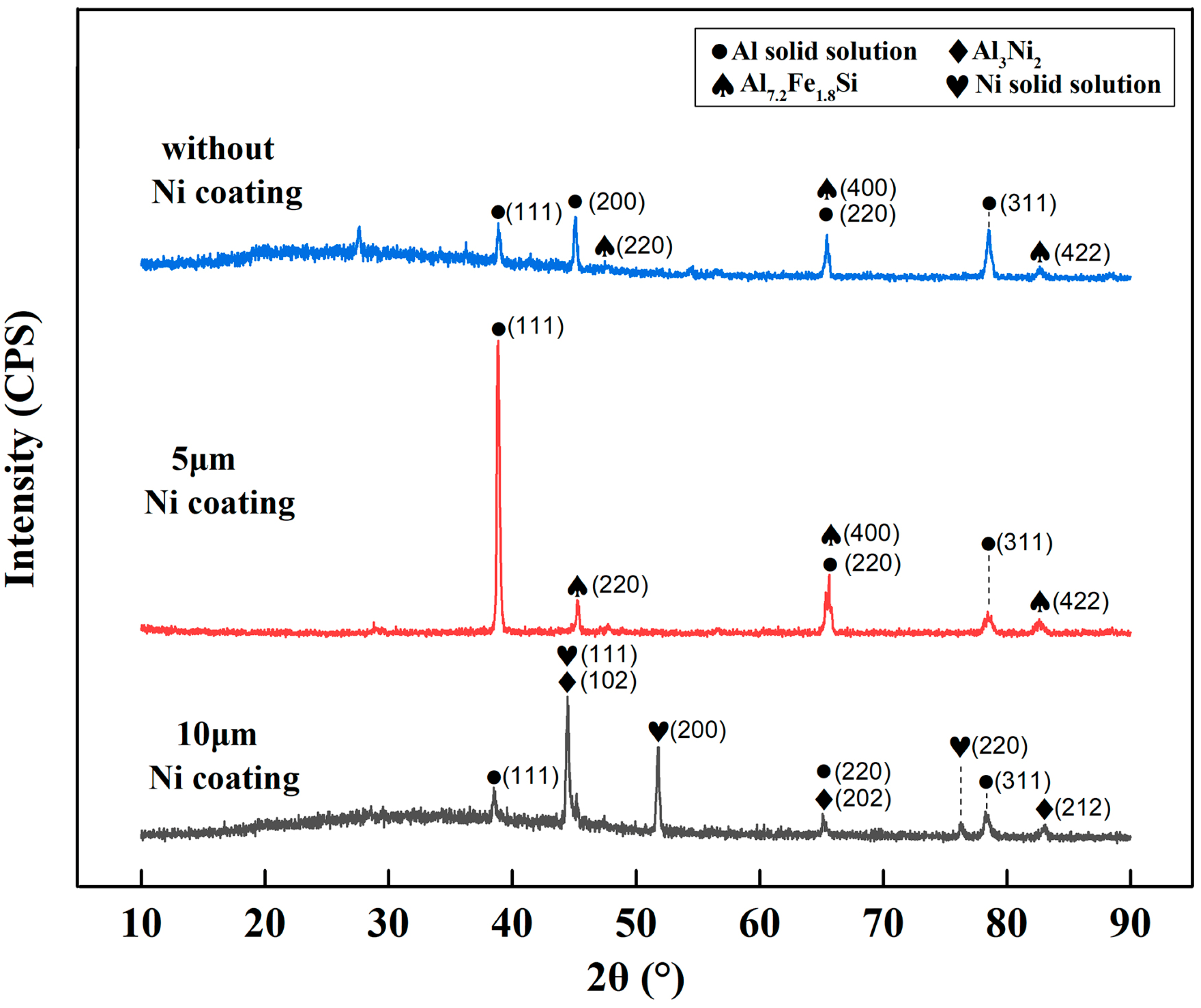
For the joint without Ni coating, the weld seam zone of the joint was mainly composed of α-Al solid solution and τ5-Al7.2Fe1.8Si. For the joint with Ni coatings of 5 μm and 10 μm thicknesses, the weld seam zone of joints consisted of α-Al solid solution, τ5-Al7.2(Fe,Ni)1.8Si, and newly formed Al3Ni2.
(3)
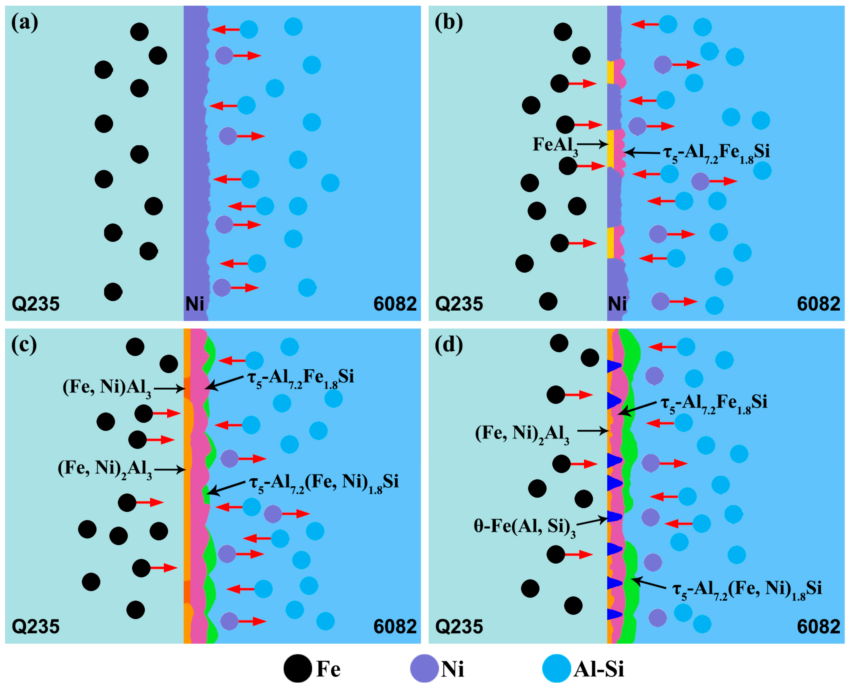
Ni coating can change the phase composition, and the brittle IMCs were from FeAl3 to (Fe, Ni) Al3 and (Fe, Ni)2Al3 at the interface reaction layer.
(4)
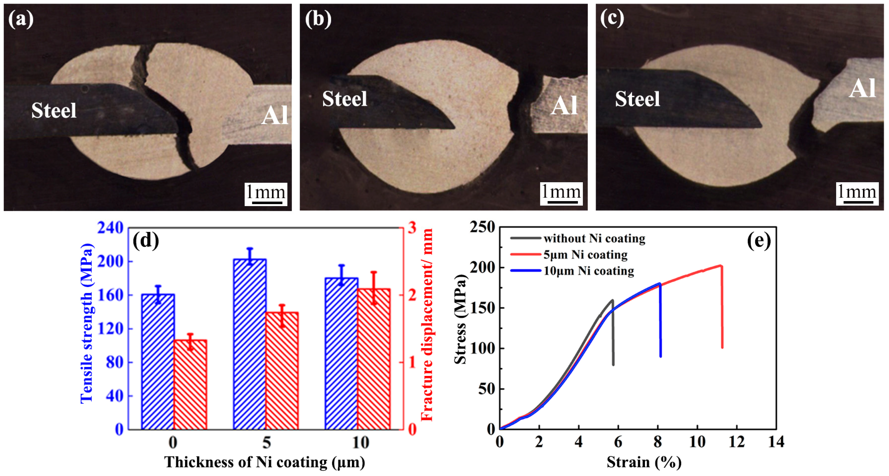
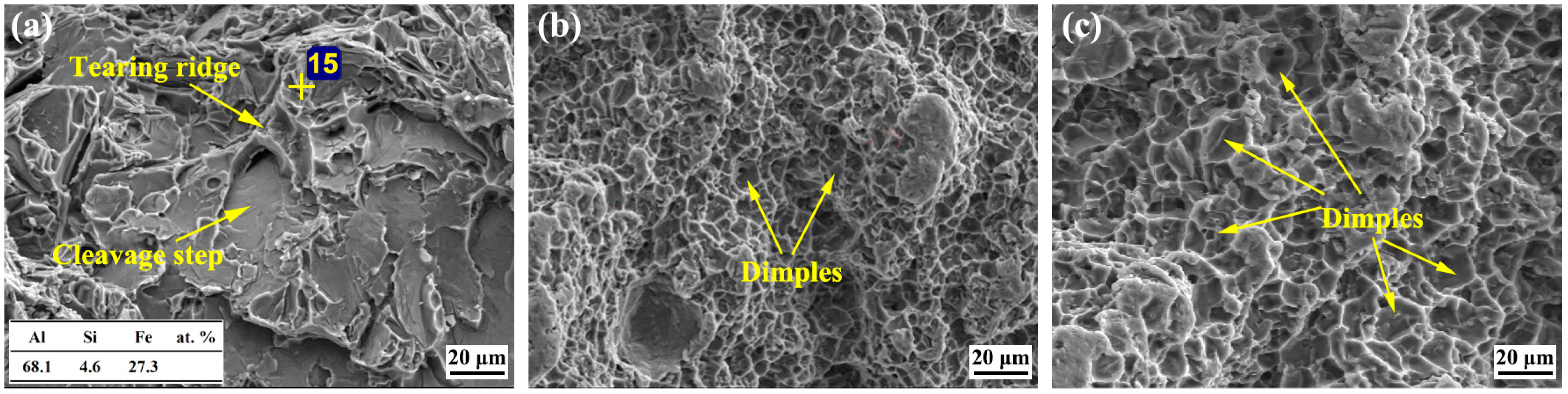
Ni coating can improve the tensile strength of Al alloy/Steel joints such that these joints cracked at the weld seam zone near the Al alloy. When the thickness of the Ni coating was 5 μm, the tensile strength of the joint reached a maximum of 202.5 Mpa. Additionally, Ni coating on the steel surface can improve the corrosion resistance of the joints.

Author Contributions

Conceptualization, C.Z., J.P. and M.W.; methodology, C.Z., Y.S. and J.R.; validation, C.Z. and M.W.; writing—original draft preparation, C.Z. and J.P.; writing—review and editing, W.L. and Y.S. All authors have read and agreed to the published version of the manuscript.

Funding

This work is sponsored by the National Natural Science Foundation of China (No. 51675249), Natural Science Research General Project of Jiangsu Province (No. 19KJB46001), the Excellent Scientific and Technological Innovation Team of Universities in Jiangsu Province and Engineering Research Center Program of Development & Reform Commission of Jiangsu Province (Grant No. [2021] 1368) and Changzhou Science and Technology Plan Project (No. CJ20190028).

Institutional Review Board Statement

Not applicable.

Informed Consent Statement

Not applicable.

Data Availability Statement

The data used to support the findings of this study are available from the corresponding authors upon request.

Conflicts of Interest

The authors declare no conflict of interest.

References

  1. Liu, Z.; Li, Y.; Zhao, J.; Fu, L.; Li, L.; Yu, K.; Mao, X.; Zhao, P. Research on Aluminum Alloy Materials and Application Technology for Automobile Lightweigh. Mater. China 2022, 41, 786–795. [Google Scholar]
  2. Kang, Y. Lightweight Vehicle Advanced High Strength Steel and Energy-Saving and Emission Reduction. Iron Steel. 2008, 6, 1–7. [Google Scholar]
  3. Singh, J.; Arora, K.; Shukla, D. Dissimilar MIG-CMT weld-brazing of aluminium to steel: A review. J. Alloys Compd. 2019, 783, 753–764. [Google Scholar] [CrossRef]
  4. Chen, Y.; Xue, S.; Wang, B.; Han, Y. Development Status and Future Direction of Welding Technology in the Automotive Lightweight. Mater Rep. 2019, 33, 431–440. [Google Scholar]
  5. Li, L.; Xia, C.; Song, Y.B.; Zhou, D.J. Application status and outlook of aluminum alloys in new energy vehicles. Light Alloy Fabr. Technol. 2017, 45, 18–25. [Google Scholar]
  6. Wu, J.; Xue, S.; Fei, W.P.; Han, Y.; Zhang, P. Present Status and Development Trend for Brazing Aluminum to Steel. Mater Rep. 2019, 33, 3533–3540. [Google Scholar]
  7. Gao, C.; Yang, J.; Li, Z.; Zhao, Y.; Liu, H.; Zhang, L. Research progress on advanced dissimilar joining methods of aluminum/steel. Weld. Join. 2021, 29, 7–20. [Google Scholar]
  8. Farhad, O.; Ehsan, S.; Meysam, T.; Fadhlina, M.; Masoud, S. On the role of molybdenum on the microstructural, mechanical and corrosion properties of the GTAW AISI 316 stainless steel welds. Journal of Materials Research and Technology 2021, 13, 2115–2125. [Google Scholar]
  9. Farhad, O.; Ehsan, H.; Meysam, T.; Ehsan, S.; Khairur, J.; Astuty, A. Microstructure, Hardness and Corrosion Be-havior of Gas Tungsten Arc Welding Clad Inconel 625 Super Alloy over A517 Carbon Steel Using ERNiCrMo3 Filler Metal. J. Mater. Eng. Perform. 2020, 29, 6919–6930. [Google Scholar]
  10. Amiri, E.; Farhad, O.; Meysam, T.; Ehsan, S.; Fadhlina, M.I. Study and selection of most appropriate filler rod for GTAW of S32750 super duplex steel joints: A comprehensive study on microstructural, mechanical and corrosion properties. Mater. Chem. Phys. 2021, 270, 124839. [Google Scholar] [CrossRef]
  11. Qin, G.L.; Wu, C.S. State-of-art of Brazing-fusion Welding Processes of Dissimilar Metals between Aluminum Alloy and Steel. J. Mech. Eng. 2016, 52, 24–35. [Google Scholar] [CrossRef]
  12. Maryam, R.; Nima, R.; Ali, M. Improvement of mechanical properties of aluminum base composite reinforced by steel Ck75 wire through explosive welding. Rev. Metal. Madrid. 2021, 57, 196. [Google Scholar]
  13. Maryam, R.; Nima, R.; Mehdipour, O. Production of steel 1006 wire reinforced aluminum base composite by explo-sive welding. Rev. Metal. Madrid. 2020, 56, 165. [Google Scholar]
  14. Shao, Z.Y.; Zhang, C.; Lin, Y.M.; Tan, Z.Y. Effect of Different Wire Composition on Microstructure and Properties of CMT Welding-brazing of Aluminum/Steel. H. Work. Technol. 2022, 51, 114–119. [Google Scholar]
  15. Shi, Z.; Li, R.; Yu, Z.; Ge, Q.; Wu, M. Effect of wettability and spreadability of AlSi5 filler and interfacial behavior of AlSi5 filler and galvanized steel with TIG welding-brazing. Weld. Technol. 2014, 43, 7–9+5. [Google Scholar]
  16. Zhang, C.; Wu, M.; Pu, J.; Shan, Q.; Sun, Y.; Wang, S.Q.; Hermann, S.K.U.G. Effect of Cu Coating on Microstructure and Properties of Al/Steel Welding-Brazing Joints Obtained by Cold Metal Transfer (CMT). Coatings 2022, 12, 1123. [Google Scholar] [CrossRef]
  17. Huang, J.-K.; Wang, Z.-Y.; Liu, N.; Yu, S.R.; Fan, D. Effect of Metal Coating on Microstructure and Properties of Aluminum/Steel Laser Welding-Brazing Joint. J. Mater. Eng. 2018, 46, 99–105. [Google Scholar]
  18. Yang, G.J.; Liu, J.W.; Han, L. Effect of Cu,Sn,Ni on property of Al-Si based solder. Weld Join. 2015, 5, 50–55+70–71. [Google Scholar]
  19. Sun, P.; Dong, Z.; Chen, Y.; Yan, H.; Luo, C.; Song, H.; Hu, Z. Characterization of Ni coating layer of Al2O3 particles and their wettability behavior in Al2O3@Ni/Al-10Si composites. Appl. Surf. Sci. 2020, 526, 146660. [Google Scholar] [CrossRef]
  20. Yang, J.; Hu, A.M.; Li, Y.L.; Zhang, P.; Chandra, S.; Yu, Z. Heat input, intermetallic compounds and mechanical properties of Al/steel cold metal transfer joints. J. Mater. Process. Technol. 2018, 272, 40–46. [Google Scholar] [CrossRef]
  21. Singh, J.; Arora, K.S.; Shukla, D.K. Lap weld-brazing of aluminium to steel using novel cold metal transfer process. J. Mater. Process. Technol. 2020, 283, 116728. [Google Scholar] [CrossRef]
  22. Hultgren, R.; Desai, P.D.; Hawkins, D.T.; Gleiser, M.; Kelley, K.K. Selected values of the thermodynamic properties of binary alloys; American Society for Metals: Metals Park, OH, USA, 1973; p. 536. [Google Scholar]
  23. Richards, R.W.; Jones, R.D.; Clements, P.D.; Clarke, H. Metallurgy of continuous hot dip aluminizing. Int. Mater. Rev. 1994, 39, 191–212. [Google Scholar] [CrossRef]
  24. Qi, J.; Song, Y.Q. Experimental studies on the diffusion reaction of Al /Ni /Fe interface. Met. Mater. Metall. Eng 2007, 8–10+14. [Google Scholar]
  25. Liu, C.T.; Jemian, W.; Inouye, H.; Cathcart, J.V.; David, S.A.; Horton, J.A.; Santella, M.L. Initial Development of Nickel and Nickel-Iron Aluminides for Structural Uses; No. ORNL-6067; Oak Ridge Natl. Lab.: Oak Ridge, TN, USA, 1984. [Google Scholar]
  26. Bertoncello, J.C.; Manhabosco, S.M.; Dick, L.F. Corrosion study of the friction stir lap joint of AA7050-T76511 on AA2024-T3 using the scanning vibrating electrode technique. Corros. Sci. 2015, 94, 359–367. [Google Scholar] [CrossRef]
  27. Pu, J.; Xie, P.; Long, W.; Wu, M.; Sheng, Y.; Sheng, J. Effect of current on corrosion resistance of duplex stainless steel layer obtained by plasma arc cladding. Crystals 2022, 12, 341. [Google Scholar] [CrossRef]
  28. Wu, J.; Liu, Y.; Li, C.; Wu, Y.; Xia, X.; Li, H. Recent Progress of Microstructure Evolution and Performance of Multiphase Ni3Al-Based Intermetallic Alloy with High Fe and Cr Conten. Acta Metall. Sin. 2020, 56, 21–35. [Google Scholar]
  29. Popov, A. Effect of electronic nature and substitution behavior of ternary microadditions on the ductility of polycrystalline nickel aluminides. Acta Mater. 1997, 45, 1613. [Google Scholar] [CrossRef]
  30. David, S.; Jemian, W.; Liu, C.; Horton, J. Welding and weldability of nickel-iron aluminides. Weld J. 1985, 64, 22. [Google Scholar]
Figure 1. Schematic diagram of the electroplating process for Ni coating on the steel surface.
Coatings 13 00418 g001
Figure 2. Schematic diagram of CMT welding-brazing process.
Coatings 13 00418 g002
Figure 3. Macrostructure of joints under different thicknesses of Ni coatings: (ac) without Ni coating; (df) with 5 μm Ni coating; (gi) with 10 μm Ni coating.
Coatings 13 00418 g003
Figure 4. The microstructure and corresponding EDS line scanning results of joints: (ac) without Ni coating; (df) with 5 μm Ni coating; (gi) with 10 μm Ni coating.
Coatings 13 00418 g004
Figure 5. XRD results of Al alloy/steel joints.
Coatings 13 00418 g005
Figure 6. Interface reaction layer growth mechanism of Al alloy/steel joint with Ni coating: (a) stage I; (b) stage II; (c) stage III; (d) stage IV.
Coatings 13 00418 g006
Figure 7. Tensile properties and fracture section morphology of joints: (a) fracture location without Ni coating; (b) fracture location with 5 μm Ni coating; (c) fracture location with 10 μm Ni coating; (d) tensile strength and fracture displacement; (e) stress-strain curves.
Coatings 13 00418 g007
Figure 8. Tensile fracture morphology of Al alloy/steel joints under different thicknesses of Ni coating: (a) without Ni coating; (b) with 5 μm Ni coating; (c) with 10 μm Ni coating.
Coatings 13 00418 g008
Figure 9. Polarization curves of Al alloy/steel joints with different thicknesses of Ni coating: (a) open circuit potential–time curves; (b) polarization curves.
Coatings 13 00418 g009
Table 1. Chemical compositions and tensile properties of base metal and flux-cored wire.
MaterialsElements (wt.%)Tensile Strength Rm/MPa
6082 Al alloyMgZnMnCuSiFeAl240
0.6–1.20.200.4–1.00.100.7–1.30.50Bal.
Q235B Steel CSiMnSPCrFe375
0.20.20.20.030.030.70Bal.
AlSi12SiCuZnMgMnFeAl
12.150.00570.00480.00020.0750.209Bal.
NOCLOCK fluxKAlF4CsAlF4
973
Table 2. Process parameters of CMT welding brazing.
ParametersValue
Welding voltage, V12.0
Welding current, A105
Welding speed, mm/min300
Shielding gas flow, L/min18
Wire feeding speed, m/min5.5
Table 3. The EDS points scanning results and possible phase of corresponding characteristic points in Figure 4.
PointsAtomic Percentage (at. %)Possible Phase
AlSiFeNi
177.54.917.6τ5-Al7.2Fe1.8Si
297.51.21.3α-Al
369.54.026.5FeAl3
476.611.112.3θ-Fe (Si, Al)3
561.30.50.238.0Al3Ni2
680.66.013.41.07τ5-Al7.2(Fe, Ni)1.8Si
798.21.10.7α-Al
869.43.415.711.5(Fe, Ni) Al3
970.88.720.5θ-Fe (Si, Al)3
1061.60.80.237.4Al3Ni2
1178.37.17.57.1τ5-Al7.2(Fe, Ni)1.8Si
1297.40.90.90.8α-Al
1369.32.418.110.2(Fe, Ni)2Al3
141.70.398.0α-Ni
Table 4. Ecorr and Icorr fitted for the curves in Figure 9.
SamplesEcorr/VIcorr/(A·cm−2)
Al alloy−0.5923.35 × 10−6
Steel−1.2005.20 × 10−5
Without Ni coating−1.0038.60 × 10−6
5 μm Ni coating−0.7425.65 × 10−6
10 μm Ni coating−0.7754.94 × 10−6
Disclaimer/Publisher’s Note: The statements, opinions and data contained in all publications are solely those of the individual author(s) and contributor(s) and not of MDPI and/or the editor(s). MDPI and/or the editor(s) disclaim responsibility for any injury to people or property resulting from any ideas, methods, instructions or products referred to in the content.

