Article

Novel Method for Deposition of Gas-Tight SiC Coatings

Osipyan Institute of Solid State Physics, the Russian Academy of Sciences, Ac. Osipyan Street 2, Chernogolovka 142432, Russia
*
Author to whom correspondence should be addressed.
Coatings 2023, 13(2), 354; https://doi.org/10.3390/coatings13020354
Submission received: 27 December 2022 / Revised: 28 January 2023 / Accepted: 1 February 2023 / Published: 3 February 2023
(This article belongs to the Special Issue Ceramic Films and Coatings: Properties and Applications)

Abstract

:
A new high-temperature method for the deposition of gas-tight silicon carbide protective coatings with low gas permeability has been developed. The free carbon atoms form during the high-temperature pyrolysis of hydrocarbon molecules. In turn, carbon reacts with molten silicon contained in the subsurface substrate layers and/or with silicon vapor. The source of silicon vapor serves the molten silicon in the heated zone of a reactor furnace. Such coatings effectively protect SiC-C-Si and SiC-C-MoSi2 ceramics, carbon–carbon composite materials, structural graphite, and refractory metals and alloys from oxidation. The conducted tests show the high thermal oxidation and thermal shock stability of deposited protective coatings, as well as their good adhesion to the substrates.

1. Introduction

Graphite, carbon–carbon composite materials (CCCMs), and silicon carbide-based composites containing carbon are widely used in the design of various devices, machines, and mechanisms. In particular, they are used in the development of aviation and rocket technologies. The application of these materials is limited to temperatures below 450–500 °C. At higher temperatures, carbon is oxidized by the oxygen contained in the air. High-density silicon carbide (SiC) ceramics (such as reaction-bonded silicon carbide) usually contain some residual silicon. This fact limits their applicability due to thermal oxidation or degradation when operating in an alkaline environment.
Therefore, the development of high-temperature protective coatings on carbon- and silicon-containing materials is an urgent task [1]. These so-called “functional coatings” can be used for the following purposes:
-
Isolation of the substrate material from contact with an oxidizing atmosphere in order to prevent corrosion;
-
Increasing the wear resistance of the surface of the product;
-
Increase in the strength of the product;
-
Surface engineering, etc.
Silicon carbide is one of the most commonly used materials for protective coatings due to its resistance to temperature variations, high corrosion resistance, and good wear resistance at high temperatures in an oxidizing environment [2,3,4]. SiC thin films and coatings on high-temperature materials can be deposited by chemical vapor deposition (CVD) [5,6,7,8], metal organic chemical vapor deposition (MOCVD) [9], and reactive chemical vapor deposition (RCVD) [10]. SiC coatings are also deposited by high-speed plasma deposition [11,12,13], thermal evaporation [14], and magnetron sputtering [15,16]. Chemical surface modification [17], sol–gel technology [18], electrolytic and electrophoretic deposition from liquid solutions [19,20], plasma chemical vapor deposition [21,22,23], and reactive diffusion coating [24] are also used to deposit SiC.
CVD is the most common method for the deposition of protective SiC coatings on carbon-containing materials. This is because of its versatility and technological ripeness. CVD allows for gas-tight, homogeneous coatings to be obtained (on large-dimension parts) with precise thickness control and improved surface morphology. These properties ensure the good protective ability of SiC coatings. The disadvantages of CVD include the high cost of reagents, low deposition rates, and difficulties with adhesion when applied to some materials due to the impossibility of forming buffer layers.
There are also other methods for the deposition of SiC coatings. Thus, to protect carbon fibers and nanotubes from oxidation, as well as to form a buffer layer, the coating can be deposited in such a way that the surface of the carbon material does not deteriorate. This can be achieved if carbon is excluded from the reaction. For example, fibers can be impregnated with mixtures of reagents containing carbon and silicon subjected to hydrolysis, followed by heat treatment such as a gradual temperature increase up to 1400 °C [25]. Additionally, to obtain a composite material, the carbon powders can be coated with a SiC layer before subsequent sintering [26].
On the contrary, the participation of silicon in the formation of a coating on SiC ceramics with a high content of residual silicon permits the production of continuous SiC coatings when only a carbon-containing component is supplied. This approach ensures not only the protection of silicon-containing material, but also the manufacturing of hermetic (gas-tight) joints for ceramic parts [27]. Pastes or slurries consisting of a finer carbon filler fraction than the siliconized graphite being coated can also be used for deposition of SiC coatings. In this way, after siliconization, the dense SiC layer is formed on the surface of the product [28]. Due to the high content of SiC and reactive bonding with the protected material, such SiC coating exhibit good adhesion and wear resistance.
In this paper, we consider a new method for the deposition of tight SiC coatings with low gas permeability. Such SiC coatings permit improvements to the thermal oxidative resistance of ceramic materials containing residual carbon and silicon, as well as carbon–carbon composite materials, especially graphites and refractory metals and alloys. We also characterized the properties of materials, coatings, and products obtained using the developed deposition technology.

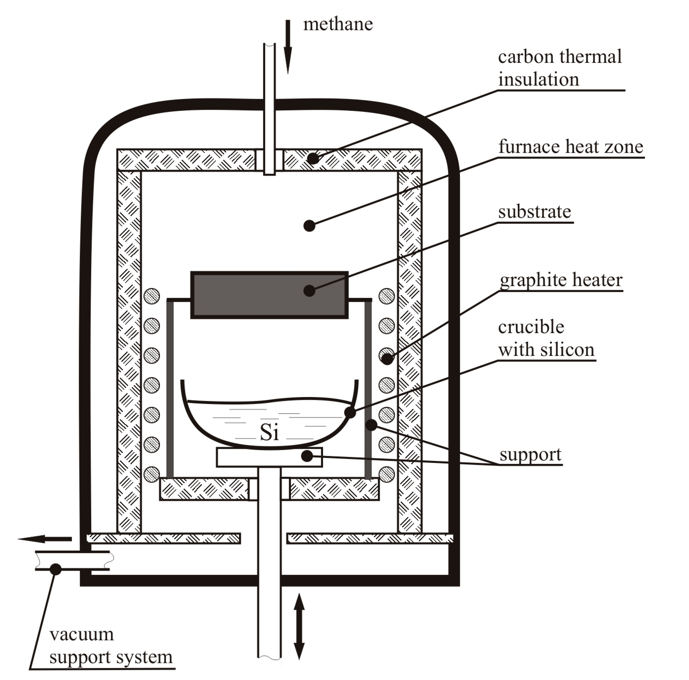
2. Materials and Methods

The technique for applying a gas-tight silicon carbide coating to a substrate material is based on the direct interaction of carbon formed during the high-temperature pyrolytic decomposition of hydrocarbon molecules (for example, methane) with a silicon melt contained in the surface layer of the material to be coated and/or silicon vapor. The source of silicon vapor is the silicon melt placed in the thermal zone of the furnace [29].
The layout of the reactor for deposition of a gas-tight SiC coating is shown in Figure 1. The process was carried out in a vacuum high-temperature furnace with a graphite heater and carbon thermal insulation. In the lower part of the thermal zone of the furnace, a crucible with silicon was located on a support, above which the coated part was placed upon special tooling. The furnace was evacuated using a fore-vacuum pump and was smoothly heated to a temperature of 1500–1800 °C until silicon melted in the crucible. After that, with the help of a gas flow regulator, methane was supplied to the thermal zone of the furnace. After reaching the required thickness of coating, the supply of methane to the thermal zone of the furnace was stopped and the heater was turned off. The coating growth rate can vary from 10 to 100 µm/h depending on the application mode and the type of surface to be protected. The vacuum supply system was left on until the furnace was completely cooled down.
Grain size of the SiC coating (from microcrystalline to nanoscale), the fraction of void, the atomic structure of grain boundaries, the composition of polytypes, and the morphology of SiC depend on the temperature in the interaction zone and the pressure of hydrocarbon gas. In this case, depending on the deposition conditions, one can controllably obtain either coating from SiC nanoparticles with a controlled content of nanopores or poreless coatings consisting of nano- or microcrystals with uniform granulometric composition.
At low temperature (1500–1600 °C) in the reaction zone, the coating structure was formed of SiC nanoparticles ranging in size from 10 to 80 nm, which were agglomerated into clusters up to several tens of microns in size (Figure 2a). These clusters compose an ordered structure on the surface of the material, forming a porous coating in one or more layers (Figure 2b,c). Such coatings have significant advantages for a number of specific applications. For example, for materials operating under conditions of intense radiation, a large positive role is played by the presence of nanocavities, which ensure the rapid emergence and annihilation of radiation defects.
At higher temperatures (1700–1800 °C), gas-tight protective coatings are formed from micro- and nanocrystals (Figure 3).
Depending on the composition of the protected material, carbon and silicon can be used to form a coating both from external or internal sources. External sources are either a crucible with a silicon melt placed in the thermal zone of the furnace or carbon from the thermal decomposition of a gaseous hydrocarbon. Internal sources are residual silicon and carbon contained in the near-surface substrate layer. Information on the components involved in the formation of coatings on various materials is given in Table 1.
Application of the developed technique makes it possible to obtain air-tight polycrystalline silicon carbide coatings with thicknesses from 300 nm to hundreds of micrometers and even several millimeters. Depending on the feed rate, pressure, and temperature of the components in the interaction zone, it is possible to change the grain size of the SiC coating from dozens of nanometers to hundreds of micrometers.

3. Results and Discussion

In this section we describe the deposition of protective SiC coatings on various high-temperature materials. The features of the formation of coatings on various materials and their influence on the characteristics of products are considered. Oxidation resistance at high temperatures, thermal shock resistance, and the influence on mechanical properties are described.

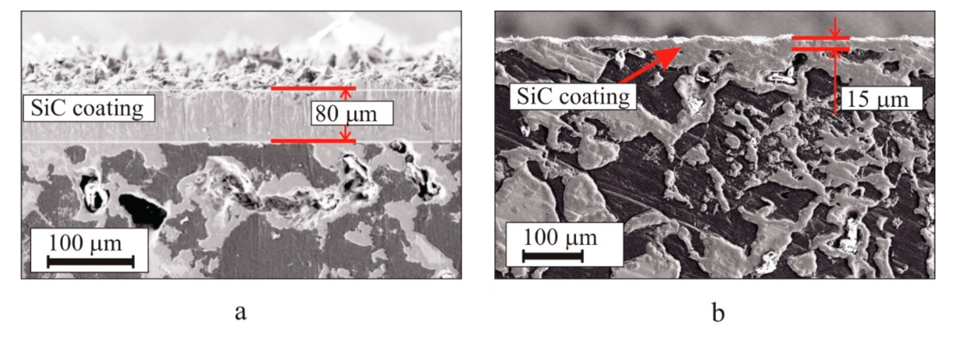
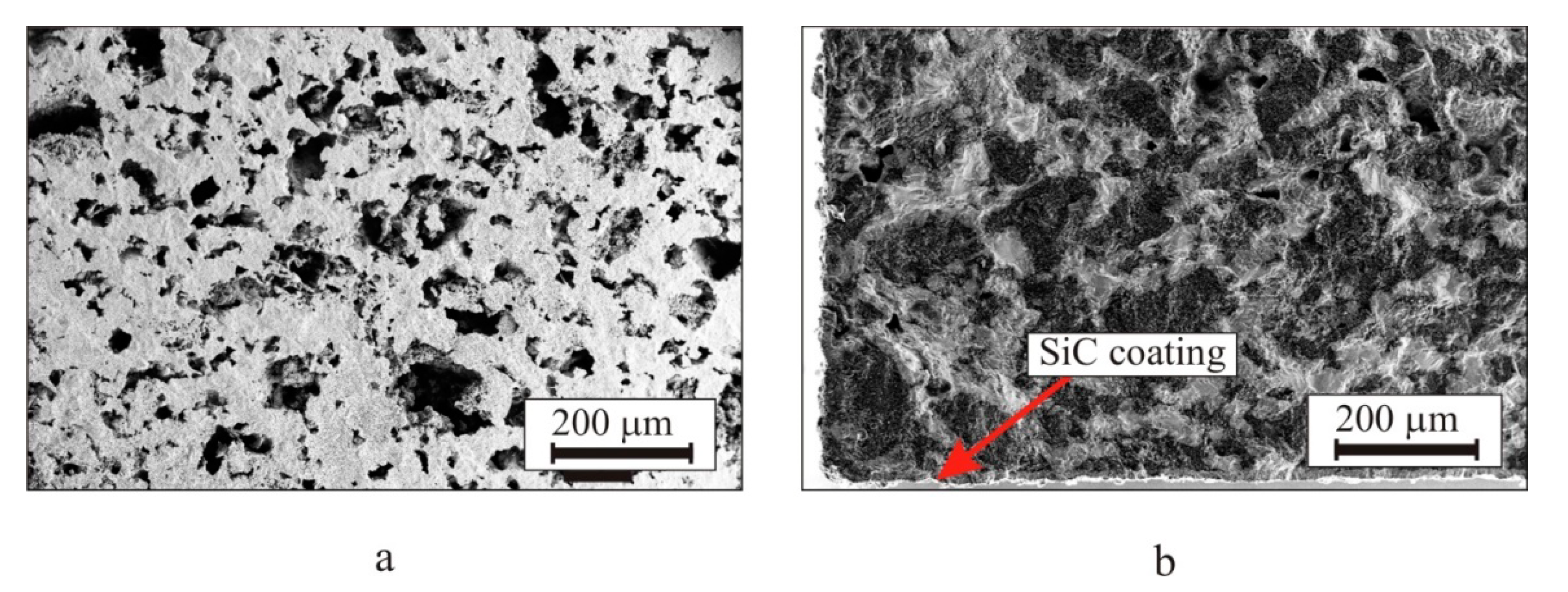
3.1. Deposition of Protective SiC Coatings on the Carbon–Carbon Composite Materials and Graphites

Carbon–carbon composite materials (CCCMs) and graphites have high strength and thermal stability in vacuum or inert environments. However, they can be oxidized by the oxygen in air at above 450–500 °C. The oxidation leads to corrosion and loss of strength and therefore limits the applicability of CCCMs and graphites. To protect CCCMs from oxidation, deposition modes were used, in which a dense SiC coating about 10 μm thick with a small grain size (80 nm) was formed. Such coating protects the substrate material from reactions with environmental components. The SiC coating also leads to a noticeable change in the size and mechanical characteristics of the coated composite material.
A CCCM with a SiC gas-tight coating is shown in Figure 4. The carbon from the surface layer of the CCCM partially participated in the formation of the SiC coating. This ensures the high adhesion of the SiC coating to the substrate and high protective properties with a thin coating.
To determine the thermal oxidative resistance of the coatings, tests were carried out on a specially prepared CCCM sample with a SiC coating. The experimental conditions were as follows: air velocity head 4–6 GPa, temperature T = 1700 °C, test time of 10 min. Figure 5 shows the test thermograms for a CCCM sample with a protective SiC coating and its appearance before and after testing. Figure 6 shows the temperature distribution over the area of the sample. Despite the local overheating of the sample surface (Figure 4), the continuity of the coating was not disturbed. The weight loss of the sample after testing was 14.6 mg, which was less than 0.1% of the total weight of the sample. Tests for thermo-oxidative resistance demonstrated the promising features of the developed technique for deposition of silicon carbide coatings on CCCMs. The coating has good protective properties up to temperatures of 1700–1750 °C.
Tight SiC coatings with low gas permeability were also deposited on graphite parts with various geometries to protect them from oxidation. The maximum dimensions of products to be coated are limited only by the dimensions of the thermal zone of the installation. Figure 7 shows examples of SiC coatings of uniform thickness that were deposited on graphite parts with various geometries.
Graphite can be used as a removable substrate to obtain polycrystalline silicon carbide in complex shapes. Figure 8 shows SiC tubes and a magnetron sputtering target made by depositing a thick layer of silicon carbide on rectangular graphite rods and a plate. After coating, the graphite was removed by annealing in air at a temperature of 1100 °C. This technique allows you to obtain macroscopic articles of various configurations from nanostructured SiC.

3.2. Deposition of Protective SiC Coatings on SiC-C-Si and Siliconized Graphites

Relatively light and wear-resistant SiC-C-Si ceramics are well suited for manufacturing complex-shaped parts. As for carbon materials, their operating conditions are limited to temperatures of 450–500 °C due to the oxidation of residual carbon. In the absence of residual carbon, their operating conditions are limited to temperatures of 1100 °C due to the oxidation of residual silicon. The atmosphere of water vapor and alkali metal salts accelerates the destruction of SiC-C-Si ceramics. Thus, a protective SiC coating should significantly limit the corrosion of such ceramics.
Polycrystalline SiC coatings with a thickness of 20–100 μm were deposited on the parts made of SiC-C-Si ceramics. These parts were produced by the impregnation of porous carbon matrices with liquid silicon. The porous carbon matrices had different residual silicon and carbon content in the volume [30,31]. It can be seen in the cross section of the coated substrate (Figure 9) that the part of the residual silicon in the near-surface open pores was involved in the formation of the coating. Single pores in the near-surface layer of the material do not have any noticeable effect on the mechanical properties of ceramics, especially in front of their significant increase from the presence of the SiC coating. The coating itself has multiple continuous bonds to the carbon and silicon carbide of the material, providing strong bonding to the substrate.
To determine the temperature stability of protective SiC coatings on SiC-C-Si ceramics, the decrease in the mass of samples due to carbon burnout when exposed to high temperature in an oxidizing atmosphere was evaluated. Figure 10 shows cross sections of the SiC-C-Si/50-40-10 ceramics without a protective coating (Figure 10a) and with a gas-tight SiC coating after annealing in air at 1000 °C for 60 h (Figure 10b). It can be seen that the structure of the material without a protective coating is severely damaged due to carbon burnout from the bulk of the material. Information about the changes in the weight of the samples is given in Table 2. The weight of parts with SiC coatings changed by less than 1%, which indicates that the coating has high functional quality.
The deposition of a SiC coating on SiC-C-Si ceramics can also improve the mechanical properties of the material by reducing the contribution of surface defects during bending and compression testing. Table 3 shows the measurement results of mechanical testing of the uncoated and coated SiC-C-Si specimens.
The SiC film deposited according to the developed method is sufficiently conformal. In other words, its thickness on the walls of complex structures is comparable to the thickness of the film on the horizontal sections of these structures. This means that the method can be used to apply protective coatings on parts that are very complex in shape.
Using the developed method for manufacturing ceramic parts with complex shapes and the technique of applying protective SiC coatings, high-temperature equipment was manufactured. Namely, inserts for thermocouples were produced and used in the test bench for a gas turbine engine (Saturn, Rybinsk). Figure 11 shows the water-cooled metal case of a gas flow thermometer with five SiC inserts for the placement of thermocouples [32,33]. In the test bench for the gas turbine engine, a test cycle was carried out where the total operating time of the equipment was about 8 h; the thermogram (Figure 12) shows that the maximum measured temperature was 1465 °C.

3.3. Deposition of SiC Coatings on SiC-C-MoSi2 Ceramic Products

SiC has good chemical compatibility and thermal stability with MoSi2, so the strength and toughness of SiC-based composites enriched in the MoSi2 phase can be greatly improved. Figure 13 shows the microstructure of a SiC-C-MoSi2 composite material with a silicon carbide protective coating. The coating makes it possible to prevent both the high-temperature oxidation of carbon particles (which are present in the material’s structure) and the low-temperature oxidation of molybdenum disilicide. Such stability is necessary during the long-term operation of such a material in the temperature range of 600–900 °C [34,35]. The coating was deposited by the gas-phase method through the exposure of the composite sample in the thermal zone of the furnace, where silicon vapors and products of high-temperature pyrolytic decomposition of methane molecules were present.
Additionally, this method can be used to obtain protective coatings for SiC-based composites reinforced with refractory metal wire, such as molybdenum, tungsten, niobium, etc. [36,37].

3.4. Deposition of SiC Coatings on Products from SiC-Si Material

A silicon carbide gas-tight coating can be deposited on materials containing residual silicon, such as modified recrystallized silicon carbide (mRSiC) or reaction-bonded silicon carbide (RBSiC). Such protective SiC coatings significantly increase the thermal and oxidative resistance of mRSiC or RBSiC (Figure 14) due to the protection against oxidation of residual silicon contained in the material.
Heaters made of recrystallized SiC ceramics “age” during operation. Due to oxidation, the cross section of the working part of the heater decreases and its electrical resistance increases. As a result, zones of local overheating are formed. In places of overheating, more intense oxidation occurs, which in turn causes a further decrease in the cross section of the heater and an increase in temperature. The process proceeds at an increasing rate and leads to the burnout of the heater. We have developed a technique for modifying RSiC [38]. This technology increases the mechanical strength and thermal shock resistance of the material. The dependence of electrical resistivity on temperature becomes more stable. Therefore, the manufacture of an mRSiC heater with a protective SiC coating is of great interest as this would increase the resistance of the heater to oxidation.
To confirm the effectiveness of the above method for manufacturing heating elements from mRSiC, a prototype heater was prepared and tested. A heating element of made of mRSiC with an outer diameter of 12 mm and a length of 180 mm was made from the working parts of a standard heating element. The protective silicon carbide coating was deposited on its surface (Figure 14a).
The tests were carried out on a stand (see the scheme in Figure 15). A computer-controlled power supply heated the heater up to ~1600 °C for two minutes, which was followed by cooling for one minute. The cycle was repeated afterwards. At the end of each heating cycle, the values of the current flowing through the heater and the voltages on the current leads were recorded.
In Figure 16, the dependence of heater resistance vs. the number of warm-up/cool-down cycles is plotted. After 2000 cycles, the change in the electrical resistance of the heater was less than 5%. The stability of electrical resistance confirms the good protective properties of the SiC coating and its high adhesion to the heater surface.

3.5. Deposition of SiC Coatings on SiC-C-MoSi2 Ceramic Products

The protective SiC gas-tight coating can also be deposited on refractory metals and metal alloys. Figure 17a shows a SiC-coated molybdenum plate that was used as a heater in an oxidizing atmosphere at a temperature of 1500 °C for about 10 h. Heater contact zones at the edges were not protected by the coating.
To achieve good adhesion with the SiC coating and prevent its delamination and destruction during temperature cycling, an intermediate layer of silicide was formed on the surface of metal (Figure 17b). In order for this to be achieved before methane was supplied to the chamber, the metal was preliminarily held in silicon vapor to form a silicide layer on its surface. Further, after the start of methane supply to the interaction zone, a silicon carbide coating was formed on a silicide layer.

4. Conclusions

The conventional CVD method for SiC deposition includes various precursors (monomethylsilane, methyltrichlorosilane, tetramethylsilane, etc.). In contrast to CVD, the proposed high-temperature method of the gas-phase deposition of protective SiC coatings has a number of significant advantages. These are the following:
--
The deposition rate is approximately two orders of magnitude higher;
--
The adhesion of the protective coating to the surface of a carbon- and/or silicon-containing material is significantly higher. This is because the process is carried out at a high temperature with the participation of carbon and silicon located directly in the substrate material;
--
Simpler technological equipment;
--
Low cost due to the speed of coating deposition and the use of more accessible and cheaper components compared to silicon-containing precursors.
Thus, a high-temperature method for the deposition of protective SiC coatings onto SiC-C-Si and SiC-C-MoSi2 ceramics, CCCMs, graphite, refractory metals, and metal alloys has been developed. The tests carried out showed high thermal-oxidative and thermal shock resistance and good adhesion, with protective coatings also capable of withstanding harsh environments.

Author Contributions

Conceptualization, S.S. and V.K.; methodology, A.K. and I.S.; formal analysis, A.K. and I.S.; writing—original draft preparation, V.K.; writing—review and editing, B.S.; supervision, B.S. and V.K.; project administration, V.K.; funding acquisition, V.K. All authors have read and agreed to the published version of the manuscript.

Funding

This research received no external funding.

Institutional Review Board Statement

Not applicable.

Informed Consent Statement

Not applicable.

Data Availability Statement

All the data required to reproduce these experiments are present in the article.

Conflicts of Interest

The authors declare no conflict of interest.

References

  1. Raj, R. Fundamental research in structural ceramics for service near 2000 °C. J. Amer. Ceram. Soc. 1993, 9, 2147. [Google Scholar] [CrossRef]
  2. Elizarova, Y.A.; Zakharov, A.I. High-temperature protective coatings of the functional purpose. New Refract. 2020, 10, 52. [Google Scholar] [CrossRef]
  3. Filonov, K.N.; Kurlov, V.N.; Klassen, N.V.; Kudrenko, E.A.; Steinman, E.A. Peculiarities of nanostructured silicon carbide films and coatings obtained by novel technique. Bull. Russ. Ac. Sci. Phys. 2009, 73, 1374. [Google Scholar] [CrossRef]
  4. Locke, C.W. SiC Films and Coatings: Amorphous, Polycrystalline, and Single Crystal Forms: In Silicon Carbide Biotechnology, 2nd ed.; Elsevier: Amsterdam, The Netherlands, 2012; Volume 379, Available online: http://books.google.com/books?hl=en&lr=&id=tdRnnGs0UsgC&oi=fnd&pg=PA17&dq=info%3 (accessed on 20 December 2022).
  5. Dhanaraj, G.; Dudley, M.; Chen, Y.; Ragothamachar, B.; Wu, B.; Zhang, H. Epitaxial ghrowth and characterization of silicon carbide films. J. Cryst. Growth 2006, 287, 344. [Google Scholar] [CrossRef]
  6. Zhang, W.G.; Hüttinger, K.J. CVD of SiC from methyltrichlorosilane. Part I: Deposition rates. Chem. Vapor Depos. 2001, 7, 167. [Google Scholar] [CrossRef]
  7. Park, K.-I.; Kim, J.-H.; Lee, H.-K.; Kim, D.K. High temperature mechanical properties of CVD-SiC thin films. Mod. Phys. Lett. B 2009, 23, 3877. [Google Scholar] [CrossRef]
  8. Powell, J.A.; Larkin, D.J.; Matus, L.G.; Choyke, W.J.; Bradshaw, J.L.; Henderson, L.; Yoganathan, M.; Yang, J.; Pirouz, P. Growth of high quality 6H-SiC epitaxial films on vicinal (0001) 6H-SiC wafers. Appl. Phys. Lett. 1990, 15, 1442. [Google Scholar] [CrossRef]
  9. Landry, C.C.; Barron, A.R. MOCVD of alumina-silica oxidation resistant coatings on carbon fibers. Carbon 1995, 33, 381. [Google Scholar] [CrossRef]
  10. Baklanova, N.I.; Zima, T.M.; Boronin, A.I.; Kosheev, S.V.; Titov, A.T.; Isaeva, N.V.; Graschenkov, D.V.; Solntsev, S.S. Protective ceramic multilayer coatings for carbon fibers. Surf. Coat. Technol. 2006, 201, 2313. [Google Scholar] [CrossRef]
  11. Han, M.X.; Zhou, W.; Zheng, D.H.; Tu, R.; Zhang, S.; Goto, T. High-speed deposition of SiC thick film by halide precursor. Key Eng. Mater. 2014, 616, 37. [Google Scholar] [CrossRef]
  12. Károlya, Z.; Bartha, C.; Mohai, I.; Balázsi, C.; Sajó, I.E.; Szépvölgyi, J. Deposition of silicon carbide and nitride based coatings by atmospheric plasma spraying. Int. J. Appl. Ceram. Technol. 2013, 10, 72. [Google Scholar] [CrossRef]
  13. Tului, M.; Giambi, B.; Lionetti, S.; Pulci, G.; Sarasini, F.; Valente, T. Silicon carbide based plasma sprayed coatings. Surf. Coat. Technol. 2012, 207, 182. [Google Scholar] [CrossRef]
  14. Wielage, B.; Wilden, J.; Schnick, T.; Wank, A. Development of SiC-composite feedstock for HVOF applications. Proc. Int. Therm. Spray Conf. 2002, 2002, 749. [Google Scholar] [CrossRef]
  15. Tang, H.D.; Tan, S.H.; Huang, Z.R. SiC coatings deposited by RF magnetron sputtering. Key Eng. Mater. 2007, 280–283, 1309. [Google Scholar] [CrossRef]
  16. Ordine, A.; Achete, C.; Mattos, O.; Margarit, I.C.P.; Camargo, S.S., Jr.; Hirsch, T. Magnetron sputtered SiC coatings as corrosion protection barriers for Steels. Surf. Coat. Technol. 2000, 133–134, 583. [Google Scholar] [CrossRef]
  17. Gadiou, R.; Serverin, S.; Gibot, P.; Vix-Guterl, C. The synthesis of SiC and TiC protective coatings for carbon fibers by the reactive replica process. J. Europ. Ceram. Soc. 2008, 28, 2265. [Google Scholar] [CrossRef]
  18. Kerans, R.J.; Hay, R.S.; Parthasarathy, T.A.; Cinibulk, M.K. Interface design for oxidation-resistant ceramic composites. J. Amer. Ceram. Soc. 2002, 85, 2599. [Google Scholar] [CrossRef]
  19. Zhitomirsky, I.; Petric, A. Cathodic electrodeposition of ceramic coatings for oxidation protection of materials at elevated temperatures. Can. J. Metal. Mater. Sci. 2002, 41, 497. [Google Scholar] [CrossRef]
  20. Sheveleva, I.V.; Zemskova, L.A.; Voit, A.A.; Zheleznov, S.V.; Kuryavyi, V.G. Relationship between electrochemical and structural properties of modified carbon fibers. Russ. J. Appl. Chem. 2007, 80, 240. [Google Scholar] [CrossRef]
  21. Daves, W.; Krauss, A.; Behnel, N.; Häublein, V.; Bauer, A.; Frey, L. Amorphous silicon carbide thin films (a-SiC:H) deposited by plasma-enhanced chemical vapor deposition as protective coatings for harsh environment applications. Thin Solid Films 2011, 519, 5892. [Google Scholar] [CrossRef]
  22. Loboda, J.; Seifferly, J.A.; Dall, F.C. Plasma-enhanced chemical vapor deposition of a-SiC:H films from organosilicon precursors. J. Vacuum Sci. Technol. A 1994, 12, 90. [Google Scholar] [CrossRef]
  23. Dai, P.Y.; Wang, Y.Z.; Liu, G.L.; Wang, B.; Shi, Y.G.; Yang, J.F.; Qiao, G.J.; Wang, H.J. Fabrication of highly dense pure SiC ceramics via the HTPVT method. Acta Mater. 2011, 59, 6257. [Google Scholar] [CrossRef]
  24. Paccaud, O.; Derré, A. Silicon carbide coating by reactive pack cementation—Part II: Silicon monoxide/carbon reaction. Chem. Vapor Dep. 2000, 6, 41. [Google Scholar] [CrossRef]
  25. Kablov, E.N.; Kuznetcov, N.T.; Sarkisov, P.D.; Graschenkov, D.V.; Sevast’yanov, V.G.; Orlova, L.A.; Simonenko, E.P. Method for Protecting Carbon-Containing Materials with Silicon Carbide. Patent RU 2350580, 27 March 2009. [Google Scholar]
  26. Nakamura, M.; Tojo, T.; Miyamoto, Y. Synthesis of ceramic bonded carbon using SiC-coated carbon particles and spark plasma sintering. Int. J. Appl. Ceram. Technol. 2012, 9, 1076. [Google Scholar] [CrossRef]
  27. Lessing, P.A.; Erickson, A.W.; Kunerth, D.C. Thermal cycling of siliconized-SiC at high temperatures. J. Mater. Sci. 2001, 36, 1389. [Google Scholar] [CrossRef]
  28. Krödel, M.R.; Ozaki, T. HB-Cesic composite for space optics and structures. Proc. SPIE 2007, 6666, 1. [Google Scholar] [CrossRef]
  29. Kurlov, V.N.; Shikunova, I.A.; Shikunov, S.L.; Ershov, A.E. Method of Applying Gastight Coating of Silicon Carbide. Patent RU 2601049, 27 October 2016. [Google Scholar]
  30. Shikunov, S.L.; Kurlov, V.N. SiC-based composite materials obtained by siliconizing carbon matrices. Tech. Phys. 2017, 62, 1869. [Google Scholar] [CrossRef]
  31. Kurlov, V.N.; Shikunov, S.L.; Shikunova, I.A. Composition of Carbon Blank for Obtaining SiC/C/Si Ceramics and Method for Obtaining SiC/C/Si Products. Patent RU 2573146, 24 December 2014. [Google Scholar]
  32. Kurlov, V.N.; Shikunova, I.A.; Shikunov, S.L. High Temperature Probe for Measurements in Gas Flow. Patent RU 165789, 10 November 2016. [Google Scholar]
  33. Kurlov, V.N.; Shikunov, S.L.; Shikunova, I.A.; Surmin, N.V.; Tihomirova, E.V.; Grishihin, S.A. Thermocouple Comb for Measuring the Temperature Field of a Gas Flow. Patent RU 160313, 10 March 2016. [Google Scholar]
  34. McKamey, C.G.; Tortorelli, P.F.; DeVan, J.H.; Carmichael, C.A. A Study of pest oxidation in polycrystalline MoSi2. J. Mater. Res. 1992, 7, 2747. [Google Scholar] [CrossRef]
  35. Meschter, P.J. Low temperature oxidation of molybdenum disilicide. Metall. Trans. A 1992, 23, 1763. [Google Scholar] [CrossRef]
  36. Mainzer, B.; Lin, C.; Frieß, M.; Riedel, R.; Riesch, J.; Feichtmayer, A.; Fuhr, M.; Almanstötter, J.; Koch, D. Novel ceramic matrix composites with tungsten and molybdenum fiber reinforcement. J. Eur. Ceram. Soc. 2021, 41, 3030. [Google Scholar] [CrossRef] [Green Version]
  37. Kaledin, A.V.; Shikunov, S.L.; Straumal, B.B.; Kurlov, V.N. SiC-based composite material reinforced by molybdenum wire. Metals 2023, 13, 313. [Google Scholar] [CrossRef]
  38. Kurlov, V.N.; Shikunov, S.L.; Shikunova, I.A. Method for Obtaining Products from Silicon Carbide Ceramics. Patent RU 2740984, 22 January 2021. [Google Scholar]
Figure 1. The layout of the reactor for deposition of gas-tight SiC coatings.
Coatings 13 00354 g001
Figure 2. Porous coating formed of SiC nanoparticles from 10 to 80 nm in size, agglomerated into clusters. (a) SiC nanoparticles ranging in size from 10 to 80 nm agglomerated into clusters up to several tens of microns in size; (b) clusters in an ordered structure on the surface of the material; (c) resulted porous coating in one or more layers.
Coatings 13 00354 g002
Figure 3. Gas-tight protective coatings formed by micro-F (a) and nanocrystals (b).
Coatings 13 00354 g003
Figure 4. Cross-section of a CCCM with a protective gas-tight SiC coating (a) and its enlarged fragment (b).
Coatings 13 00354 g004
Figure 5. Test thermograms for a CCCM sample 50 mm in diameter with a protective SiC coating (a) and its appearance before (b) and after (c) testing.
Coatings 13 00354 g005
Figure 6. Temperature distribution over the area of the CCCM sample with a protective SiC coating.
Coatings 13 00354 g006
Figure 7. Examples of gas-tight SiC coatings of uniform thickness on the large graphite parts with complicated geometries.
Coatings 13 00354 g007
Figure 8. SiC rectangular tubes with a wall thickness of 1–1.5 mm (a) and a SiC magnetron sputtering target of 70 mm in diameter and 6 mm in thickness (b), which were obtained by deposition onto removable graphite substrates.
Coatings 13 00354 g008
Figure 9. Cross section of a SiC-C-Si ceramic substrate with a deposited protective gas-tight SiC thick (a) and thin (b) coating.
Coatings 13 00354 g009
Figure 10. Microstructure of composite material SiC-C-Si/50-40-10 without a coating (a) and with a gas-tight SiC coating (b) after annealing at 1000 °C in air for 60 h.
Coatings 13 00354 g010
Figure 11. Thermal probes for temperature measurement in a high-temperature gas flow with brake chambers (a,b) and a comb with thermal probes as an assembly (c).
Coatings 13 00354 g011
Figure 12. Thermogram recorded by thermocouples placed in silicon carbide inserts with a protective SiC coating.
Coatings 13 00354 g012
Figure 13. Micrograph of the structure of a SiC-C-MoSi2 ceramic composite material with a protective SiC coating: black areas represent carbon, dark gray represents SiC, and light gray represents MoSi2. (a) low magnification; (b) high magnification.
Coatings 13 00354 g013
Figure 14. Protective SiC coating on recrystallized (a) and reaction-bonded (b) SiC.
Coatings 13 00354 g014
Figure 15. Scheme of the stand and a photograph of the testing process for the mRSiC heater with a protective SiC coating.
Coatings 13 00354 g015
Figure 16. Dependence of heater resistance on the number of heating/cooling cycles.
Coatings 13 00354 g016
Figure 17. Protective gas-tight SiC coating on a molybdenum heating element (a). Phase analysis of the heating element’s cross section (b).
Coatings 13 00354 g017
Table 1. Features of SiC coating deposition on various refractory materials.
Substrate MaterialCarbon
from the Substrate
Silicon
from the Substrate
Carbon
from the External Source
Silicon
from the External Source
CCCMs and graphiteyesnoyesyes
SiC-C-Si, siliconized graphitesyesyesyesyes
SiC-C-MoSi2yesnoyesyes
Modified RSiCnoyesyesyes
Metals and alloysnonoyesyes
Table 2. Weight of samples from SiC-C-Si/50-40-10 ceramics without a coating and with a protective SiC coating before and after annealing.
Sample DescriptionWeight of
Sample
before Annealing, g
Weight of
Sample after Annealing, g
Weight Loss, %
Sample 1, without coating29.3518.7636.08
Sample 2, without coating25.1916.3335.17
Sample 3, with protective SiC coating28.8228.680.48
Sample 4, with protective SiC coating24.2124.050.66
Table 3. Comparison of the strength characteristics of SiC ceramics with SiC-C-Si/50-40-10 composition without coating and with a gas-tight SiC coating.
PropertyWithout CoatingWith Coating,
20 °C
With Coating, 1000 °C
Compression strength, MPa398 ± 19472 ± 11483 ± 8
Bending strength, MPa126 ± 6204 ± 11203 ± 7
Disclaimer/Publisher’s Note: The statements, opinions and data contained in all publications are solely those of the individual author(s) and contributor(s) and not of MDPI and/or the editor(s). MDPI and/or the editor(s) disclaim responsibility for any injury to people or property resulting from any ideas, methods, instructions or products referred to in the content.

