Article

Study of Particulate Fouling Inhibition Characteristics on a Novel Composite Coating

1
School of Energy and Power Engineering, Northeast Electric Power University, Jilin City 132012, China
2
Aviation Engineering School, Air Force Engineering University, Xi’an 710038, China
3
Vertiv Technology (Xi’an) Limited Liability Company, Xi’an 710075, China
*
Author to whom correspondence should be addressed.
Coatings 2023, 13(2), 274; https://doi.org/10.3390/coatings13020274
Submission received: 4 January 2023 / Revised: 16 January 2023 / Accepted: 20 January 2023 / Published: 25 January 2023
(This article belongs to the Collection Feature Paper Collection in Corrosion, Wear and Erosion)

Abstract

:
Particulate fouling is a common fouling in heat exchange equipment, it causes tube corrosion and increases flow resistance. Particulate fouling increases the hidden danger of equipment and requires high treatment costs. In this paper, a novel Ni−P−TiO2 composite coating is prepared on 316 stainless steel using electroless plating and the fouling inhibition characteristics of the novel composite coating are studied using a dynamic monitoring experimental system. The experimental results show that the fouling thermal resistance of the Ni−P−TiO2 composite coating is obviously lower than that of 316 stainless steel under the same working conditions. With the increase in cooling water velocity and inlet temperature, the surface fouling thermal resistance decreases, while, with the increase in particle concentration, the fouling thermal resistance increases. Based on DLVO theory, it is found that the surface energy of Ni−P−TiO2 composite coating is close to the best surface energy for inhibiting particulate fouling deposition, which can significantly inhibit particulate fouling deposition. Compared with the stainless-steel surface of a conventional plate heat exchanger, the Ni−P−TiO2 composite coating not only inhibits the accumulation of particulate fouling, but also reduces the adhesion strength of particulate fouling; additionally, the fouling is easier to strip off the heat exchange surface, which realizes the lasting and efficient fouling inhibition on the heat exchange surface. The research results can provide a data reference for the fouling inhibition design and daily efficient operation of heat exchangers.

1. Introduction

Particulate fouling is one of the most common types of fouling in heat transfer equipment. It is a fouling layer formed by the deposition of large amounts of particles in cooling water on the heat transfer surface [1]. The cooling medium is generally natural fresh water (lakes or rivers) or sea water in the heat transfer equipment, which is rich in inorganic salts, sediment, and other particles. So, it is difficult to remove the particles using a simple water treatment process. In addition, the circulating cooling water system is mostly open, external particles are also easy to invade, and it provides many “convenient conditions” for the accumulation of particulate fouling. The deposition of particulate fouling in heat exchange equipment has caused a series of equipment operation safety and maintenance problems, such as pipe corrosion and increases in flow resistance, shutdown maintenance, and repair time. It directly or indirectly leads to a significant increase in fuel consumption and carbon dioxide emissions [2,3,4]. Besides, the cost of fouling treatment is also very high. It is estimated that the total annual cost of fouling treatment in developed countries accounts for is about 0.25% of GDP. According to this standard, the cost of fouling treatment in 2021 is estimated about CNY 285.9 billion in China. It can be seen that the harm of the fouling problem in heat exchange equipment cannot be underestimated.
The fouling deposition mechanism is called “one of the unsolved problems in the field of heat and mass transfer” because it is nonlinear, changes over time, and there are many factors affecting the fouling deposition process. The deposition characteristics of heat transfer equipment are studied by means of experiments and numerical simulation. Xu experimentally studied the fouling deposition characteristics of MgO nanoparticles on the heat transfer surface of a plate heat exchanger, reinforced tube, and arranged vortex generator [5,6,7,8]. The particulate fouling characteristics on the herringbone corrugated plate heat exchanger surface are studied under different conditions [9]. The Al2O3 and MgO particulate fouling characteristics in the reinforced tube are studied by the experiment and simulation; the results show that the thermal resistance asymptotic value of particulate fouling increases with the decrease in shear force [10]. The influence of fluid velocity, oversaturation, and wall temperature on CaCO3 fouling deposition on the heat exchange surface were analyzed [11]. Nikkhah explores the influence factors of fouling thermal resistance of CuO/water nanoparticles in an experiment. In the study of the factors affecting the particulate fouling deposition characteristics, the mechanism of particulate fouling deposition has also been gradually deeply understood [12]. The formation mechanism of particulate fouling on the liquid side of the reinforced tube is investigated. The results show that the surface shear stress, particle diameter, and concentration are related to the adhesion probability and deposition adhesion intensity factor. The asymptotic value of the reinforced pipe is higher than that of ordinary tubes [13]. The particulate fouling on the heat transfer surface is investigated in a numerical simulation based on the CFD multiphase method coupled with Lagrangian particle tracking (LPT) and Euler methods [14]. The interaction mechanism among the turbulent structure, heat transfer, and particulate fouling deposition on the corrugated heat transfer surface by means of experiment and numerical simulation was studied [15]. The cooperative deposition mechanism of particulate fouling and microbial fouling was investigated under different working conditions through experiments [16]. A large number of studies have effectively promoted the understanding of the deposition mechanism of particulate fouling. However, due to the complexity of the particulate fouling deposition process, the deposition mechanism of particulate fouling on the heat exchange surface has not been completely revealed, leading to the slow development of fouling inhibition countermeasures and technology on the heat exchange surface. At present, some common technical means, such as high-pressure water [17] and chemicals [18,19], can to a certain extent inhibit or reduce the fouling accumulation on the heat exchange equipment surface, but it is also easy to bring a series of problems to the environment and equipment, such as water pollution, corrosion equipment, etc. [20,21]. Under the pressure of the water resource shortage and sustainable development, the methods are gradually limited and eliminated. The development of surface modification technology and bionics provides new ideas for cleaning and efficiently controlling fouling in heat transfer equipment. Some studies have shown that coatings such as diamond−like carbon film (DLC) [22] and biomimetic nano−coating based on the lotus leaf effect [23] can effectively reduce fouling deposition, which proves that the coating has the characteristics of fouling inhibition from the technical perspective. A coating of perfluoropolyether and nano−ceramic oxide powder is coated on the stainless steel and greatly reduces the adhesion of fouling on the surface [24]. The Plasma Electrolytic Oxidation coatings with embedded copper particles can produce significant antifouling during the first 20 days of immersion [25]. It is found that the Ni−P and Ni−Cu−P-PTEE coatings on the heat transfer surface by electroless have good inhibition to CaCO3 and CaSO4 crystallization fouling [26,27]. The chemical silver plating on the heat transfer surface can significantly reduce the adhesion of biological fouling [28]. The polymethylmethacrylate-doped boron nitride coating on a stainless−steel plate of the plate heat exchanger was prepared and it showed strong fouling inhibition characteristics in a CaCO3 fouling experiment [29]. Zaghloul can effectively increase the mechanical property of material by improving the polyethylene composites [30,31,32,33]. Jindal finds that the plate heat exchanger coated with Ni−P−PTFE effectively reduces the accumulation of dairy product fouling, while, at the same time, reducing the adsorption and growth of bacteria on the surface [34]. The Ni−P−PTFE and DLC coatings significantly change the surface energy of the substrate and significantly reduce the adhesion of aluminum silicate fouling [35]. The TiO2 nanoparticles have received extensive attention due to their unique physical and chemical properties [36,37,38]. TiO2 nanoparticles are added to the Ni−P plating solution to form a composite coating, which shows significant advantages in hardness, corrosion resistance, and bacteriostasis [39,40,41,42]. Some of these characteristics may significantly enhance the ability of the composite coating to inhibit particulate fouling accumulation.
In this paper, the particulate fouling accumulation is inhibited or reduced using composite coating technology on the plate heat exchanger. The Ni−P−TiO2−composite−modified coating is coated on 316 stainless steel. The particulate fouling deposition characteristics of the plate heat exchanger coated with Ni−P−TiO2−composite-modified coating are experimentally studied under different operating conditions (cool medium inlet velocity, temperature, and particle concentration). The specific mechanism of the novel composite−modified coating−inhibiting particulate fouling accumulation is discussed. The research results show that the Ni−P−TiO2 composite coating can effectively inhibit the deposition of particulate fouling on the heat exchange surface.

2. Material and Method

2.1. Preparation and Analysis of Material

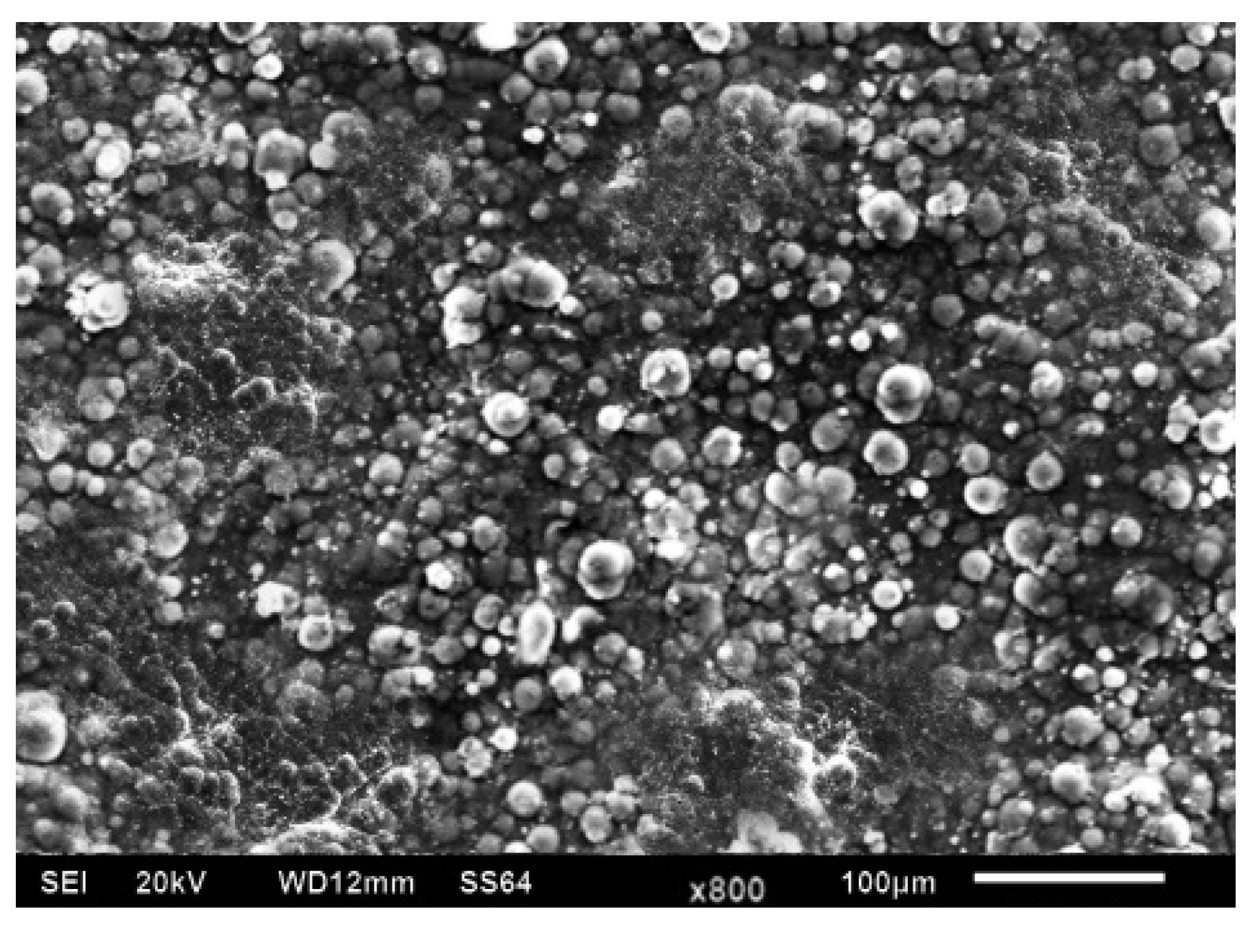
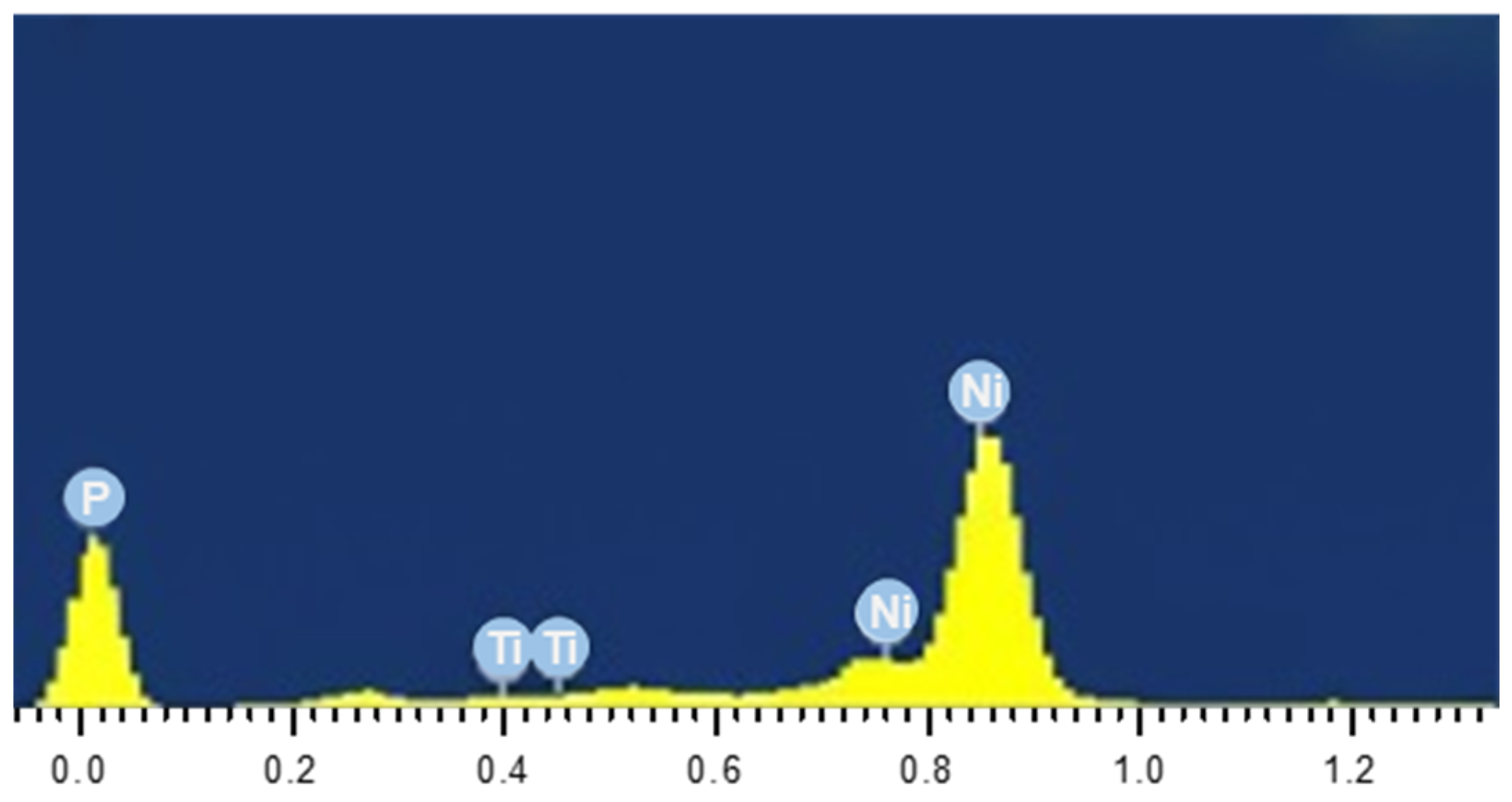
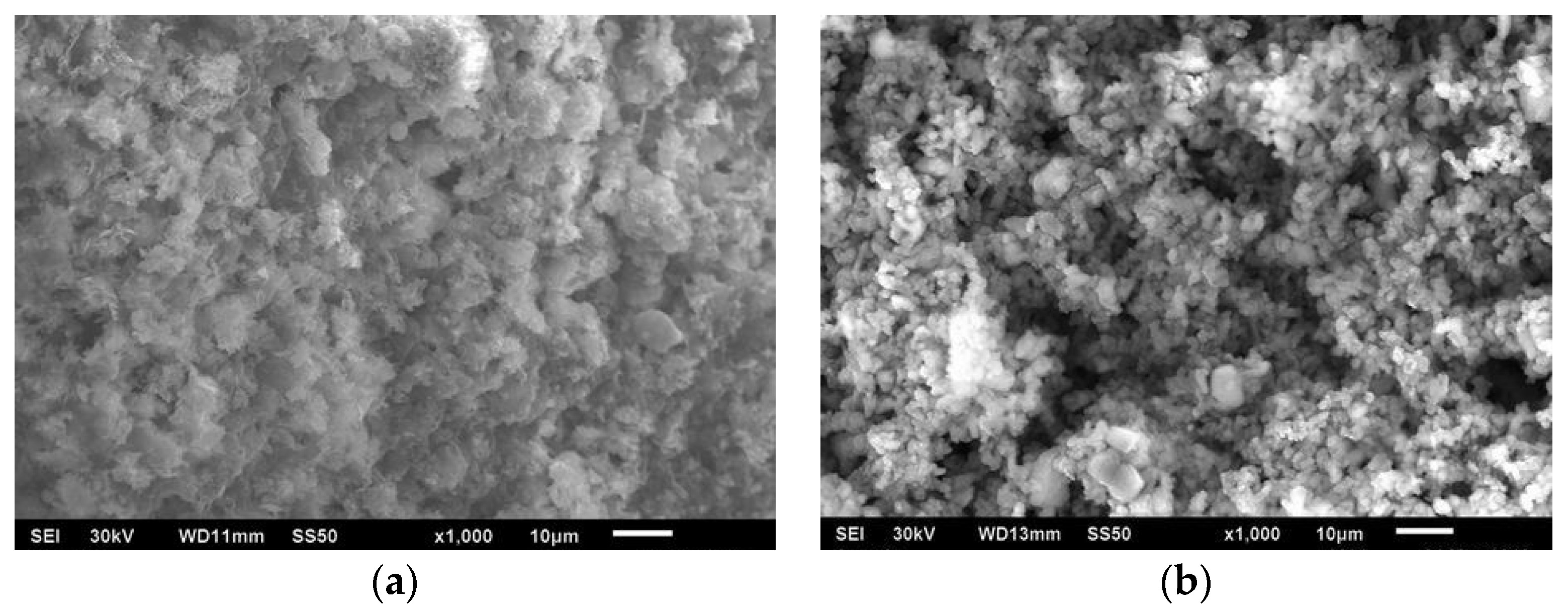
2.1.1. Preparation and Morphology Analysis of Composite Coating

In this paper, Ni−P−TiO2 composite modified coating was coated on 316 stainless steel using chemical composite plating. The plate was herringbone with a thickness of 0.6 mm and an included angle of 120°. The other dimensions of the coated plate were shown in Table 1. The 316L stainless steel was pretreated by processes such as sandpaper grinding, alkali liquor degreasing, water washing, and acid washing. In order to improve the binding force between the Ni−P−TiO2 coating surface and the substrate surface. First, it was necessary to plate the nickel on the 316 stainless steel and then further plate the Ni−P−TiO2 on the substrate surface. The composition plating solution was: 20–30 g·L−1 sodium sulphate, 20–30 g·L−1 sodium monophosphate, 10–20 g·L−1 sodium acetate trihydrate, 10–20 g·L−1 trisodium citrate dihydrate, 15–30 mL·L−1 lactic acid, 1 g·L−1 nano-TiO2 particles, and 2–4 g·L−1 surfactant. The fabricated temperature was 88 ± 2 °C and the plating time was 2 h. There was no obvious accumulation of TiO2 nanoparticles at the bottom of the cup throughout the plating process, indicating that the composite plating solution has good dispersion and thermal stability. Figure 1 shows the microtopography of the coated Ni−P−TiO2 composite coating. It can be seen that the globular cells are uniformly distributed on the coated Ni−P−TiO2 composite coating, which is caused by the co-deposition of the nickel wrapped in TiO2 nanoparticles. On the whole, the composite coating was relatively smooth, with strong binding force with the substrate, and has no surface defects such as stomata and coating peeling cracking.
The element of Ni−P−TiO2 composite coating is analyzed using Energy Dispersive Spectroscopy and the energy spectrum image is shown in Figure 2. The element P, Ni, and Ti are observed and the content of Ti is in the range of 6.12–7.34 wt.%. The results show that the Ni−P−TiO2 coating has been successfully prepared on the 316 stainless steel.

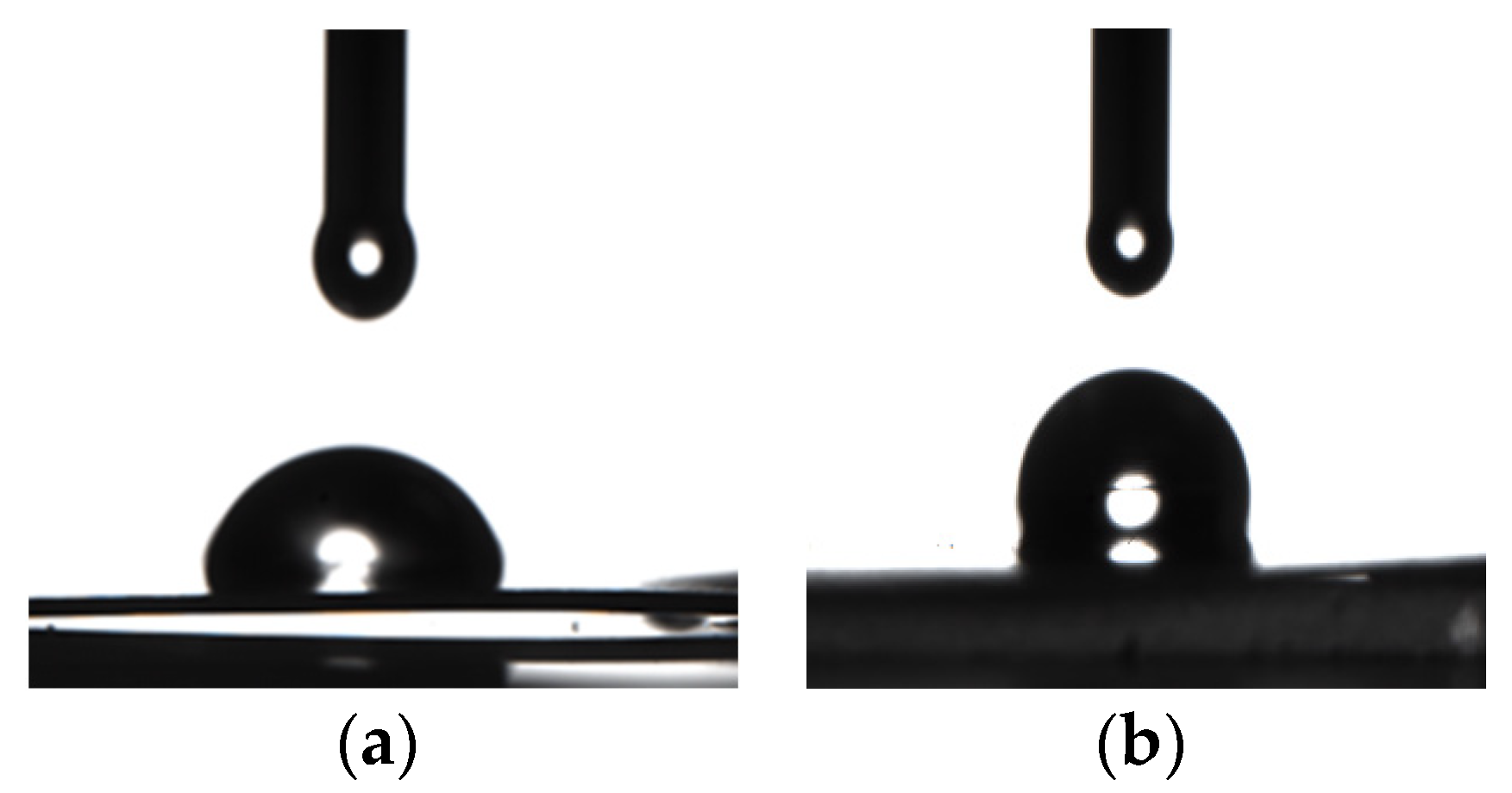
2.1.2. Measurement of Contact Angle and Analysis of Surface Energy

The surface free energy has a significant effect on the fouling accumulation on the heat transfer surface. In this paper, the contact angles of 316 stainless steel and Ni−P−TiO2 composite coating were measured using the contact angle tester (SDC-200S). Ethylene glycol, distilled water, and diiodomethane were used as the test liquids. The contact angle of the sample surface was measured many times based on the hanging drop method. The average surface energy of the 316 stainless steel and the Ni−P−TiO2 composite coating were calculated based on Young’s equation [43]. The specific measurement and calculation results are shown in Table 2. The contact angle is shown in Figure 3 when the test liquid was distilled water.

2.2. Experimental Method

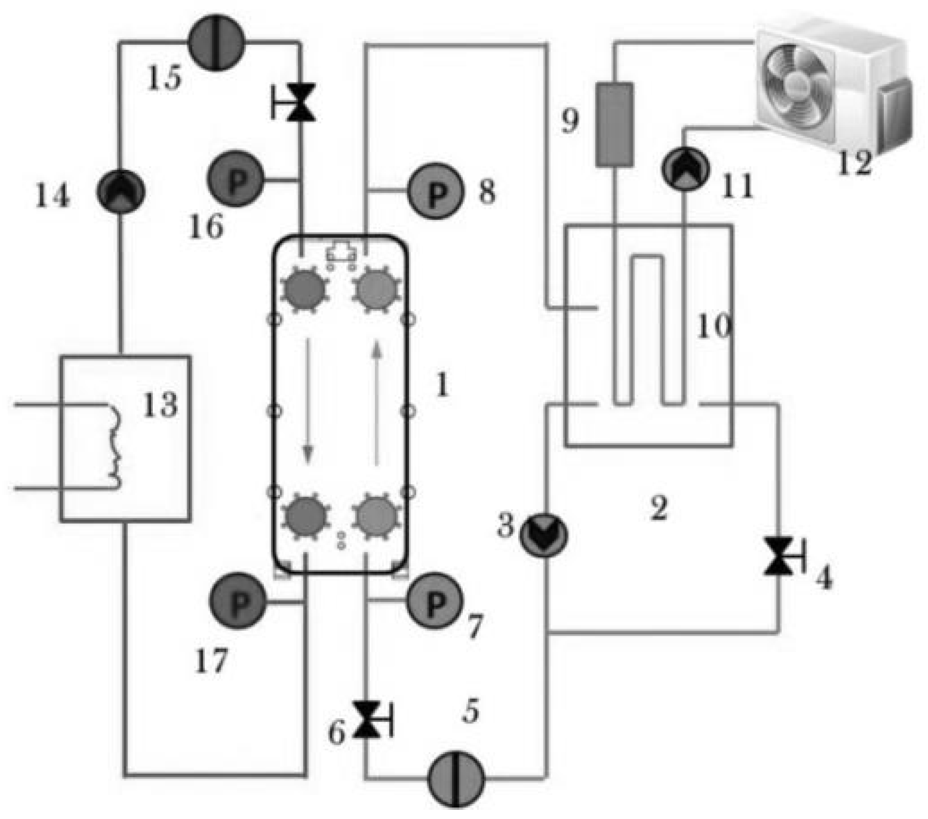
2.2.1. Experimental System

Figure 4 shows the experimental system for the dynamic monitoring of particulate fouling on the plate heat exchanger, which mainly includes four parts: low temperature fluid circulation system, high temperature fluid circulation system, cooling system, and data acquisition system. The MgO nanoparticles are added in low temperature fluid to simulate the particulate fouling deposition process in cooling water. When high and low temperature fluid exchange heat in the plate heat exchanger, the MgO nanoparticles in the cooling water will accumulate on the plate heat exchanger surface. Eventually, a stable fouling deposition is formed on the plate surface, which results in the heat transfer performance of the plate heat exchanger being reduced. The inlet and outlet temperature of the cold and hot fluid are collected by the data acquisition system in real time, which is for further calculating the fouling thermal resistance on the plate heat exchanger surface.

2.2.2. Experimental Theory

The basic measurement and calculation theory of fouling thermal resistance in this experimental system are introduced here. The heat exchange of the plate heat exchanger Φ is equal to the heat gain of low temperature circulating fluid Φ2 and to the heat loss of high temperature circulating fluid Φ1:
Φ = k A Δ t m = q m 1 c p ( t 1 in t 1 out ) = q m 2 c p ( t 2 out t 2 in )
In the formula, k is the total heat transfer coefficient; W/(m2·K), A is the heat transfer area, m2; qm is the mass flow rate, kg/h; cp is the specific heat capacity at constant pressure, J/(kg·K); t1 and t2 are the temperature of high−temperature and low-temperature circulating fluid, respectively, K.
The relative error of the heat balance is defined by considering the heat loss of the plate heat exchanger:
η = Φ 1 Φ 2 Φ 1 × 100 %
If |η| ≤ 5%, the data are considered reasonable for collection.
k = Φ A   Δ t m = Φ 1 + Φ 2 2 A   Δ t m = q m 1 c p ( t 1 in t 1 out ) + q m 2 c p ( t 2 out t 2 in ) 2   A Δ t m  
Then, calculate the fouling thermal resistance:
R f = 1 k 1 k 0
k0 and k are the total heat transfer coefficient of the plate exchanger under clean condition and fouling condition, respectively, W/(m2·K).
Therefore, the total heat transfer coefficient of the plated Ni−P−TiO2 composite coating under the clean condition and fouling condition can be calculated by measuring the parameters (qm1, qm2, t1, and t2). Then, that the particulate fouling thermal resistance value Rf of the Ni−P−TiO2 composite coating according to Equation (4) is calculated.
The wall shear force τs is calculated using Equation (5) and Equation (6):
f = d e Δ P / ( 2 L ρ u 2 )
τ s = f ρ u 2 / 2
f is the Fanning friction factor. ΔP is the differential pressure, Pa. ρ and u are the density and velocity of fluid (kg/m3, m/s). de is the equivalent diameter, m.
The optimal surface free energy (static) that causes the particles to adhere to the surface is obtained based on the extended DLVO theory [43]:
γ s , min = 1 2 ( γ b LW + γ l LW )
The γ s LW , γ b LW (testing, 49.89 MJ/m2), and γ l LW (21.8 MJ/m2) are the Lifshitz–van der Waals (LW) non−polar component of the heat transfer surface, MgO nanoparticles, and the water.

2.2.3. Error Analysis of Experimental System

The measuring equipment used in this study has been calibrated in accordance with NIST traceability standards. All the experimental error and the considered calculation parameters associated with the sensor in use are listed in Table 3. The error of parameters can be obtained by the following calculation. Assume that y is an indirectly measured function, which can be calculated from several directly measured functions in Equation (8). The deviation of y is shown in Equation (9).
y = f ( x 1 , x 2 x n )
Δ y = f x 1 Δ x 1 + f x 2 Δ x 2 + + f x n Δ x n                                             d y y = f x 1 d x 1 x 1 + f x 2 d x 2 x 2 + + f x n d x n x n
The fouling thermal resistance studied is the indirect measurement value, which is calculated by the known formula and direct measurement value. The direct measurement values include temperature, pressure, flow, etc. The maximum error values of the instruments used to measure these parameters are shown in Table 4.
Temperature measurement error:
ε t = ( 0.2 % ) 2 + ( 0.01 % ) 2 + ( 0.05 % ) 2 = 0.2064 %
Pressure measurement error:
ε p = ( 0.1 % ) 2 + ( 0.01 % ) 2 + ( 0.05 % ) 2 = 0.1122 %
Flow measurement error:
ε q v = ( 0.5 % ) 2 + ( 0.05 % ) 2 + ( 0.01 % ) 2 = 0.5025 %
Logarithmic mean temperature difference error:
ε Δ t m = ( Δ t m t 1 in ) 2 ε t 2 + ( Δ t m t 1 out ) 2 ε t 2 + ( Δ t m t 2 in ) 2 ε t 2 + ( Δ t m t 2 out ) 2 ε t 2 = 0.2071 %
Total heat transfer coefficient error:
ε Φ = ε q v 2 + ε Δ t 2 = ( 0.50 % ) 2 + ( 0.2950 % ) 2 = 0.5806 %
ε k = ε A 2 + ε Φ 2 + ε Δ t m 2 + ( 5 % ) 2 = ( 0.05 % ) 2 + ( 0.5806 ) 2 + ( 0.2056 % ) 2 + ( 5 % ) 2 = 6.693 %
The relative errors of the temperature, pressure, and flow measurements of the experimental platform meet the engineering requirements (less than ±1%) and the relative error of the total heat transfer coefficient is less than ±10%.

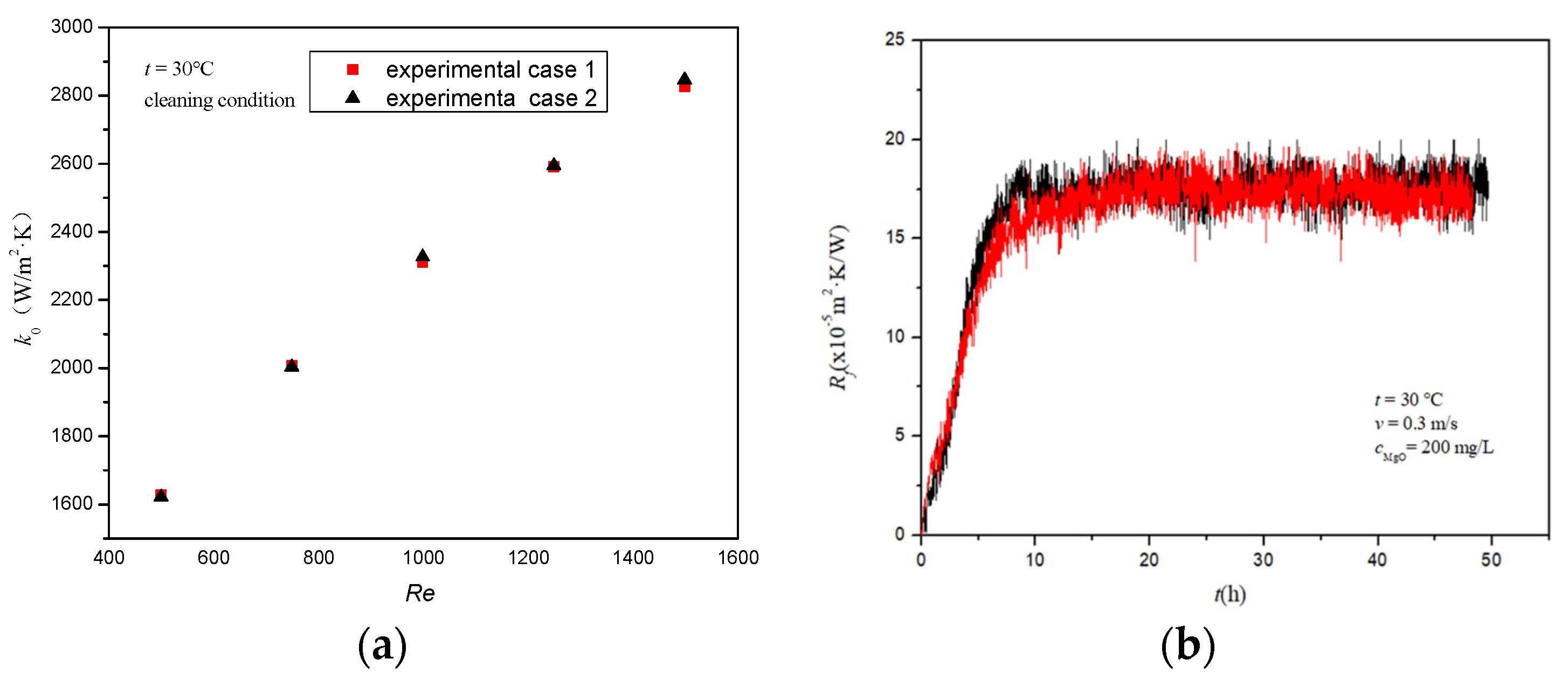
2.2.4. Stability Verification of the Experimental System

To verify the stability of the experimental system, whether the total heat transfer coefficient under the clean condition and the fouling heat resistance under the given working condition change or not are tested. It can be seen from the test results provided in Figure 5 that the total heat transfer coefficient of the plate heat exchanger measured under the clean condition has good stability under various working conditions. The relative error of the fouling thermal resistance asymptotic value is less than 1% by repeated experiments, which further shows that the experimental system has good stability.

3. Results and Discussion

Based on the dynamic monitoring system of particulate fouling on the heat transfer surface, the influence of the velocity and temperature of the inlet cooling water and MgO nanoparticle concentration on the fouling characteristics of the Ni−P−TiO2 composite coating were studied. The fouling inhibition performance of the Ni−P−TiO2 composite coating was further studied by comparing the particulate fouling thermal resistance of 316 stainless steel and Ni−P−TiO2 composite coating. Figure 6 shows a microtopography of particulate fouling deposition on the Ni−P−TiO2 composite coating and the 316 stainless steel with a fluid velocity of 0.2 m/s and the MgO nanoparticle concentration of 200 mg/L. It can be seen that the deposited particle layer on the 316 stainless steel is relatively tight, indicating that the fouling layer has a strong binding force with the surface. Therefore, the fouling layer on the 316 stainless steel is difficult to be stripped by the fluid and contributes to the further attachment and deposition of particles. While the micromorphology of the deposited particle layer on the Ni−P−TiO2 composite coating shows the flocculent loose structure. Compared with that on the 316 stainless steel, the deposited particle layer on the Ni−P−TiO2 composite coating has a poor binding force and is more easily separated by the fluid. This is due to the addition of TiO2 nanoparticles in the preparation of composite coating, in which the surface is covered with a spherical bulge structure. It is easy to form a loose porous structure when the fouling particles deposit on the surface. The deposited particles are easy to break away from the surface and return to the circulating cooling water under the fluid washing.

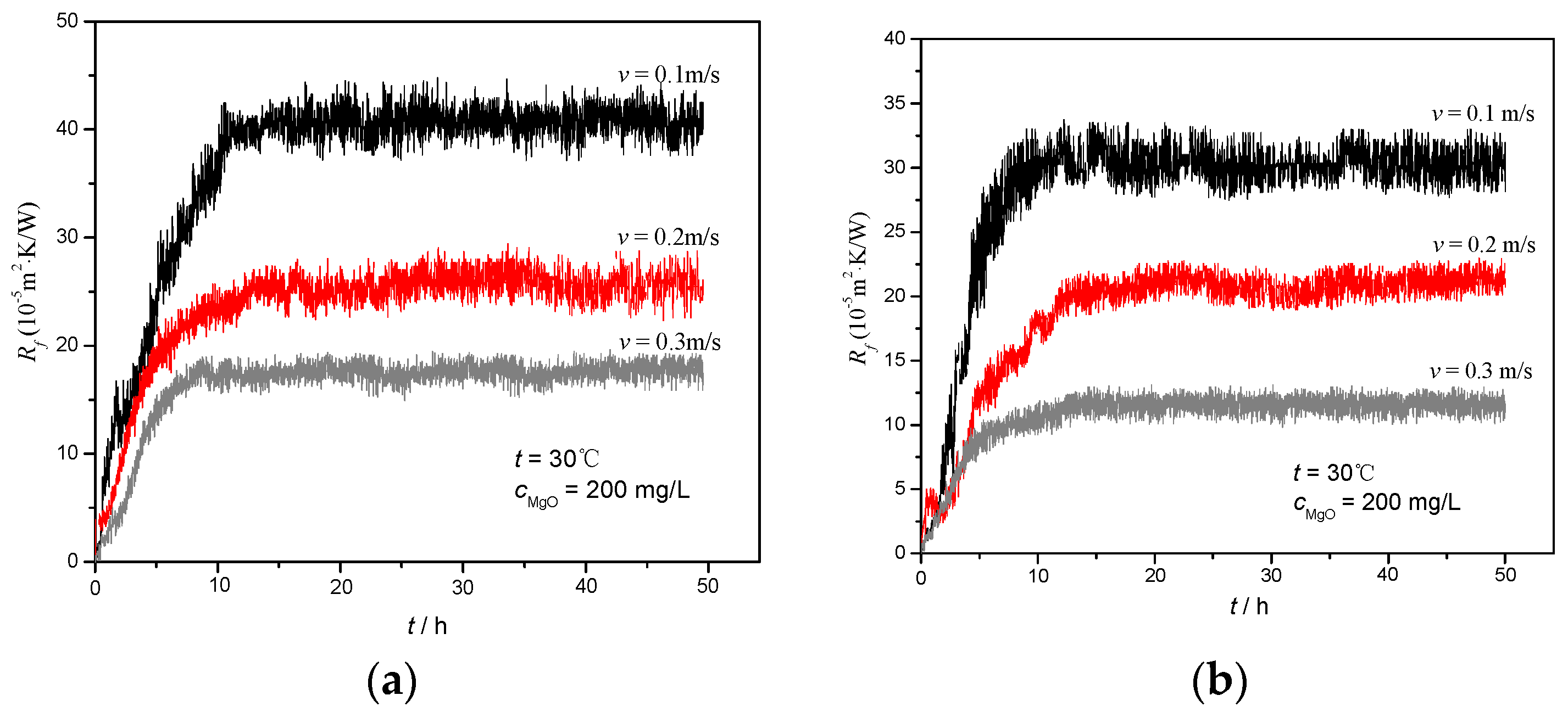
3.1. Effect of Cooling Water Velocity on Fouling Thermal Resistance Characteristics of Heat Transfer Surface

Figure 7 shows the change of the particulate fouling thermal resistance of 316 stainless steel and Ni−P−TiO2 composite coating under the cooling water velocity of 0.1–0.3 m/s. It can be seen that under the same working condition, the growth of the particulate fouling thermal resistance on the heat transfer surface has no obvious induction period. Additionally, the fouling thermal resistance decreases with the increasing cooling water velocity.
The influence of the cooling water velocity on the shear force of the heat exchange wall is shown in Figure 8a. With the increase in the cooling water velocity, the shear force of the fluid on the flow channel of the plate heat exchanger increases significantly, which strengthens the erosion and shedding of the particulate fouling, and finally keeps the fouling thermal resistance stable at a low value. The shear force exerted on the Ni−P−TiO2 composite coating is significantly less than that exerted on the 316 stainless steel under the high velocity. When the cooling water velocity is larger, the fouling thermal resistance of the Ni−P−TiO2 composite coating reduction is more significant. It indicates that the fouling layer on the composite coating is relatively loose and can be stripped by a small shear force. It shows that the Ni−P−TiO2 composite coating can achieve a highly efficient fouling inhibition.
Figure 8b shows the change in the asymptotic value of the fouling thermal resistance on the Ni−P−TiO2 composite coating and 316 stainless steel at different fluid velocities. Under the same working condition, with the increase in the cooling water velocity (0.1–0.3 m/s), the asymptotic value of the fouling thermal resistance on the Ni−P−TiO2 composite coating decreases by from 22.54% to 34.41%. In the case of large fluid velocity, the fouling thermal resistance of the Ni−P−TiO2 composite coating decreases more than that of 316 stainless steel. It shows that the Ni−P−TiO2 composite coating can not only reduce the attachment of fouling particles but that, at the same time, the attachment strength of the fouling thermal resistance is significantly reduced. The fouling layer accumulated on the Ni−P−TiO2 composite coating is more stripped back into the fluid at a large cooling water velocity, it keeps the amount of fouling accumulation on the composite coating at a lower level.

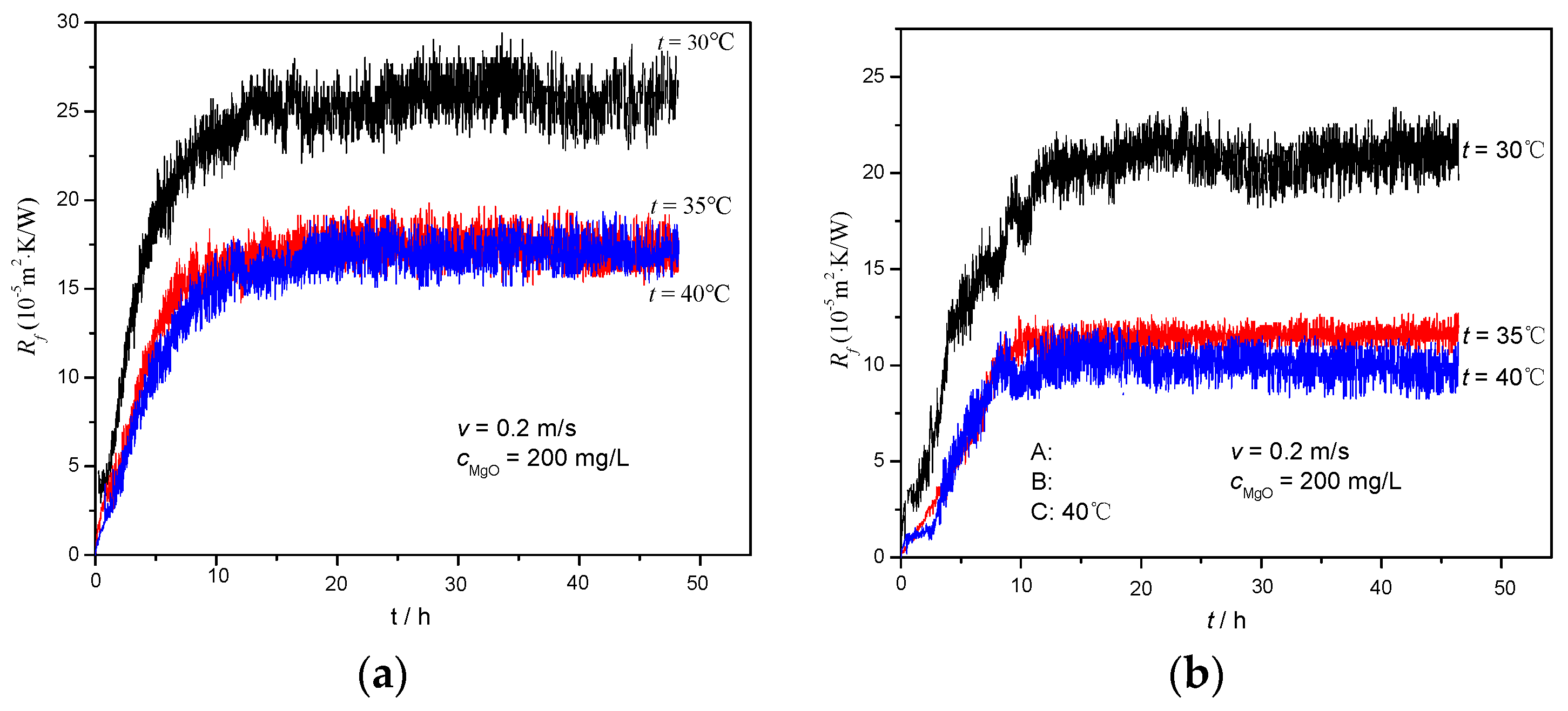
3.2. Effect of Cooling Water Temperature on Fouling Thermal Resistance Characteristics of Heat Transfer Surface

Figure 9 shows the changes of the fouling thermal resistance on 316 stainless steel and Ni−P−TiO2 composite coating at a cooling water temperature of 30–40 °C. It can be seen that, as the inlet temperature of the cooling water increases, the asymptotic values of the fouling’s thermal resistance on the 316 stainless steel and the Ni−P−TiO2 composite coating gradually decreases. Although the initial concentration of the MgO nanoparticles is the same, the Brownian motion of the particles increases with the increasing cooling water temperature and the MgO nanoparticles become easier to agglomerate. When a large number of MgO nanoparticles deposit at the bottom of the water tank or heat transfer channel, a larger particle cluster is formed on the heat exchange surface. The particle cluster is more easily stripped by the fluid and it is difficult to form a stable fouling layer on the heat exchange surface. Therefore, the asymptotic value of the fouling thermal resistance on the heat exchange surface remains at a low level. When the temperature of the cooling water changes from 30 to 35 °C, the decrease in the range of the asymptotic value of the fouling resistance is significantly greater than that at temperatures from 35 to 40 °C. Therefore, on the premise of meeting the heat exchange demand, reasonably adjusting the cooling water temperature can help to reduce the deposition of MgO nanoparticles on the heat exchange surface. With the increase in the cooling water inlet temperature, the asymptotic value of particulate fouling thermal resistance on the Ni−P−TiO2 composite coating decreases by 25.15%–39.14% compared with that on the 316 stainless steel.

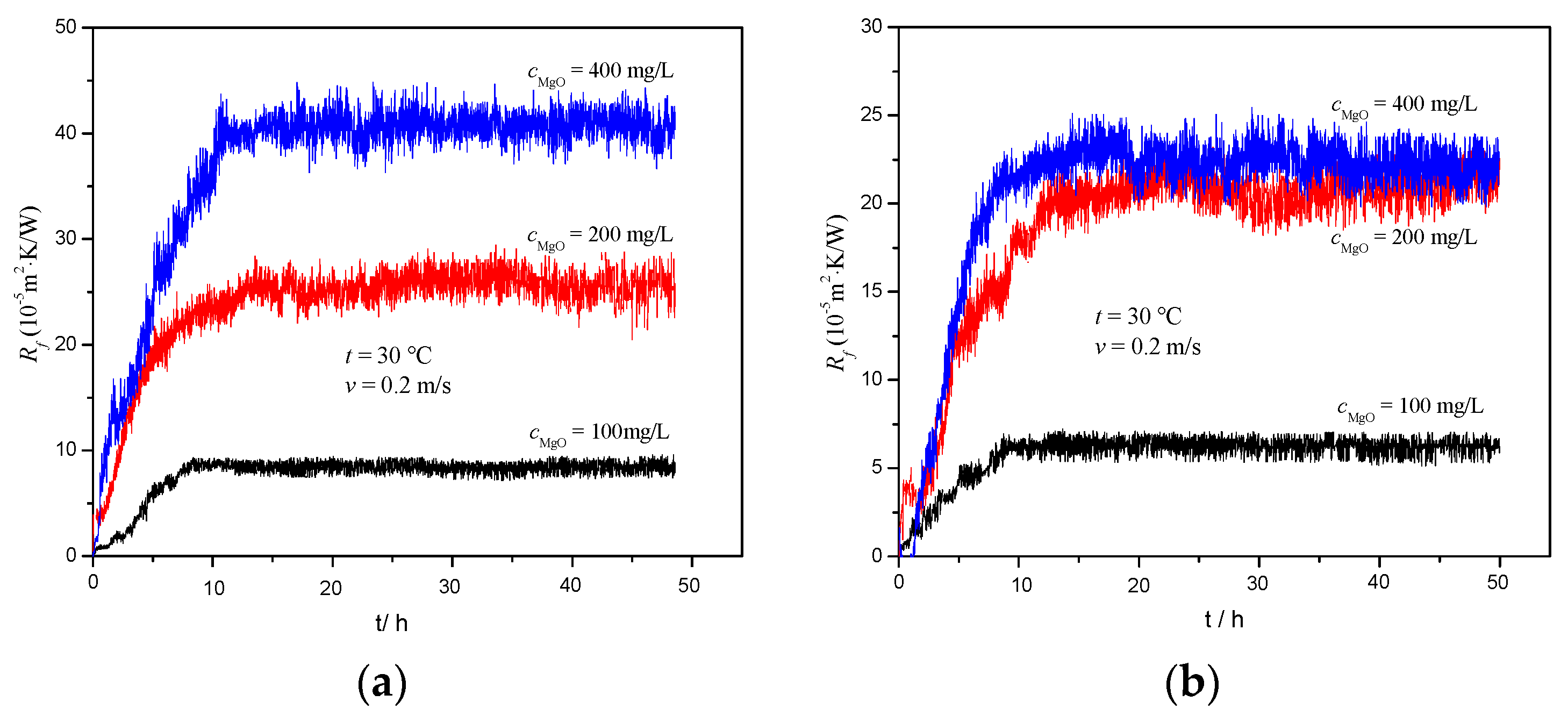
3.3. Effect of MgO Nanoparticle Concentration on Fouling Thermal Resistance Characteristics of Heat Transfer Surface

Figure 10 shows the change of the fouling thermal resistance on the plate heat exchanger surface with a MgO nanoparticle concentration of 100, 200, and 400 mg/L. It can be seen that, for both the Ni−P−TiO2 composite coating or the 316 stainless steel, with the increase in the MgO nanoparticle concentration, the fouling deposition rate and the fouling thermal resistance increases rapidly. The increase in the particle concentration in cooling water will lead to a larger particle concentration gradient between the fluid and the wall and it can significantly strengthen the mass transfer process of particles to the wall and significantly increase the probability of particle deposited on the wall. At a given fluid velocity, the shear force of the fluid to the wall does not increase significantly with the increasing particle concentration, which causes the asymptotic value of the fouling thermal resistance on the plate heat exchanger surface to increase with the particle concentration.
When the MgO nanoparticle concentration increases from 100 to 200 mg/L, the fouling thermal resistance on the Ni−P−TiO2 composite coating and 316 stainless steel increases by 205% and 231%, respectively. When the concentration of the MgO nanoparticles increases from 200 to 400 mg/L, the fouling heat resistance on 316 stainless steel increases by 59%, while the fouling heat resistance increases by only 12% on the Ni−P−TiO2 composite coating. At this time, it significantly reduces the increased range of particulate fouling heat resistance on the heat transfer surface. Therefore, the effect of the particle concentration on the fouling thermal resistance is not linear. When the particle concentration exceeds a certain value, the effect of particle concentrations on the transport of particles to the wall is reduced. When the particle concentration is large, the particle agglomeration phenomenon is obvious. The large particle clusters often form deposits on the stagnation area such as the channel and valve, but are not easy to deposit on the plate area with large flow disturbance. Then, the effect of coating characteristics on the adhesion strength becomes the main factor to control the particulate fouling deposition. In the range of the MgO particle concentration change (100–400 mg/L) in the experiment, the fouling thermal resistance on the Ni−P−TiO2 composite coating decreases by 24.98%–45.36% compared with that on the 316 stainless steel, which shows that the Ni−P−TiO2 composite coating has a strong fouling inhibition performance.

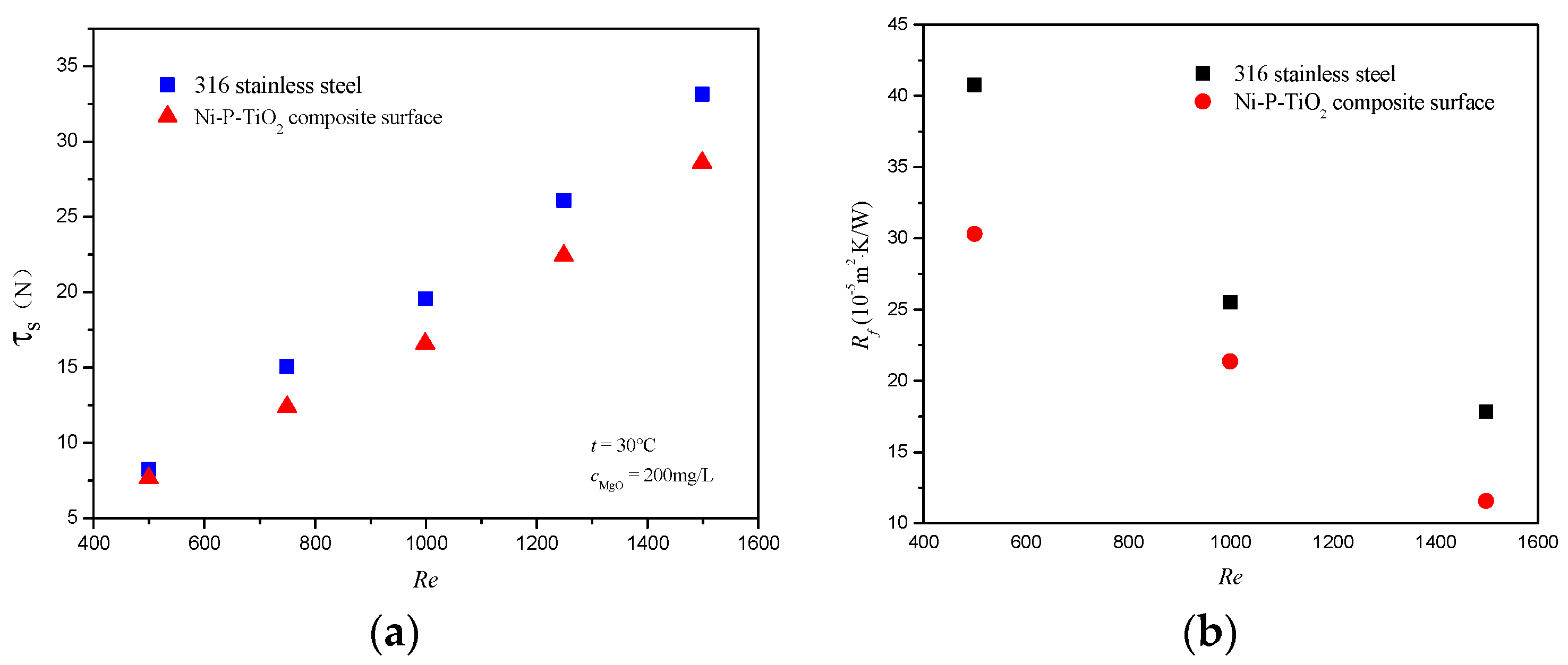
3.4. Analysis of Fouling Inhibition Characteristics on Ni−P−TiO2 Composite Coating

Figure 11 shows the macroscopic topography of the Ni−P−TiO2 composite coating (left) and 316 stainless steel (right) after the particulate fouling experiment. It can be seen that the quantity of particles deposited on the Ni−P−TiO2 composite coating is less. It is found that the particles’ adhesion strength on the Ni−P−TiO2 composite coating was poor in the cleaning process and the deposited particles are easier to remove. However, the particles’ adhesion strength is higher on the 316 stainless steel, so a relatively stable fouling layer is formed on the 316 stainless steel and the cleaning is more difficult.
In the case of the low-inlet velocity of cooling water, the wall shear forces of the Ni−P−TiO2 composite coating and 316 stainless steel are nearly equal. Under the same working conditions, the surface characteristics become the main factor affecting the deposition of MgO nanoparticles on the heat transfer surface. In this paper, the surface energy is calculated based on the tested contact angle of 316 stainless steel and Ni−P−TiO2 composite coating. Additionally, the influence of the surface characteristic change from the Ni−P−TiO2 composite coating on the particulate fouling adhesion is further analyzed.
Based on DLVO theory, the optimal surface energy to minimize the depositing amount of MgO nanoparticles is calculated (34.41 MJ/m2), which is close to the surface energy (35.93 MJ/m2) of Ni−P−TiO2 composite coating in this paper. This is the reason that the asymptotic value of fouling resistance on the composite coating is significantly lower than that on the stainless steel. On the one hand, at high fluid velocity, the shear force of fluid on the wall increases significantly. Compared with the stainless steels, the particulate fouling layer on the Ni−P−TiO2 composite coating is porous and loose, which is easy to strip back into the cooling water. On the other hand, the coated Ni−P−TiO2 composite coating significantly reduces the adhesion strength of the MgO nanoparticle on the surface. Under the same working conditions, the particulate fouling on the Ni−P−TiO2 composite coating is more easily stripped back into the circulating cooling water. Finally, the particle deposition on the Ni−P−TiO2 composite coating remains low for a long time. It realizes the lasting cleaning and fouling inhibition of the heat exchange equipment.

4. Conclusions

In this paper, the Ni−P−TiO2 composite coating was coated on the 316 stainless steel in a plate heat exchanger as the substrate and the characteristics of the fouling particles deposited on the composite coating were further studied in an experiment. The fouling thermal resistance data of MgO nanoparticles on the Ni−P−TiO2 composite coating were obtained and the specific mechanism of the fouling inhibition of the Ni−P−TiO2 composite modified was investigated. The following conclusions are obtained:
(1)
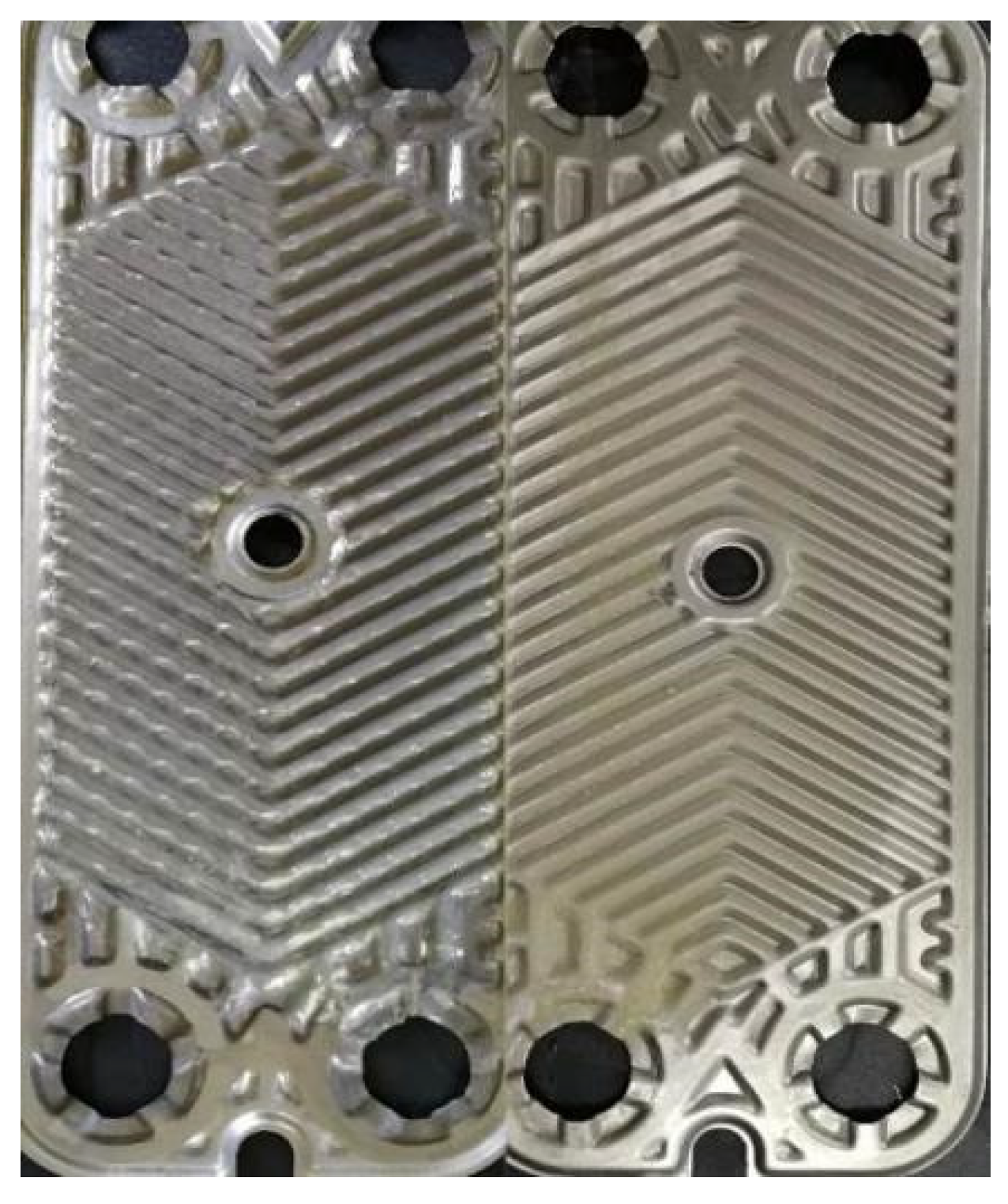
The Ni−P−TiO2 composite coating coated on the 316 stainless steel as the substrate significantly changed the surface energy and microstructure of the original stainless steel.
(2)
At varied cooling water velocity (0.1–0.3 m/s), inlet temperature (30–40 °C), and MgO nanoparticle concentration (100–400 mg/L), the asymptotic value of the nano−MgO particulate fouling on the Ni−P−TiO2 composite coating was reduced by 25.15%–45.26% compared with the uncoated 316 stainless steel.
(3)
Based on DLVO theory, the surface energy of the Ni−P−TiO2 composite coating (35.93 MJ/m2) is close to the optimal surface energy (34.41 MJ/m2) for inhibiting the MgO nanoparticle deposition. The Ni−P−TiO2 composite coating can not only reduce the nanoparticle adhesion to the wall but also the adhesion strength of the attached fouling layer. The fouling is easier to be stripped off at high fluid velocity, which causes the surface to remain clean for a longer time.

Author Contributions

Conceptualization, Y.W. and Z.L.; methodology, Y.W.; validation, Z.L., W.F. and T.Z.; investigation, W.X.; data curation, W.F. and T.Z.; writing—original draft preparation, Z.L.; writing—review and editing, Y.W.; project administration, Y.W. and Z.L. All authors have read and agreed to the published version of the manuscript.

Funding

This research was funded by the National Natural Science Foundation of China (Grant No. 51906035), National Science and Technology Major Special Funding (No. J2019-I-0016-0015), Open Foundation of MOE Key Laboratory of Thermo-Fluid Science and Engineering, Xi’an Jiaotong University (KLTFSE2019KFJJ03) and Scientific Research Project of Jilin Provincial Department of Education (JJKH20210113KJ).

Institutional Review Board Statement

Not applicable.

Informed Consent Statement

Informed consent was obtained from all subjects involved in the study.

Data Availability Statement

Not applicable.

Conflicts of Interest

The authors declare that they have no known conflict of interest.

References

  1. Schnöing, L.; Augustin, W.; Scholl, S. Fouling mitigation in food processes by modification of heat transfer surfaces: A review. Food Bioprod. Process. 2020, 121, 1–19. [Google Scholar] [CrossRef]
  2. Pourabdollah, K. Fouling formation and under deposit corrosion of boiler firetubes. J. Environ. Chem. Eng. 2021, 9, 104552. [Google Scholar] [CrossRef]
  3. Awais, M.; Bhuiyan, A.A. Recent advancements in impedance of fouling resistance and particulate depositions in heat exchangers. Int. J. Heat Mass Transf. 2019, 141, 580–603. [Google Scholar] [CrossRef]
  4. Sholahudin; Giannetti, N.; Yamaguchi, S.; Saito, K.; Tanaka, K. A cost effective and non-intrusive method for performance prediction of air conditioners under fouling and leakage effect. Sustain. Energy Technol. Assess. 2020, 42, 100856. [Google Scholar]
  5. Xu, Z.M.; Dong, B.; Du, X.Y.; Wang, B.L. Experimental study on particulate fouling in plate heat exchangers. J. Chin. Soc. Power Eng. 2013, 33, 539–543. [Google Scholar]
  6. Xu, Z.M.; Wang, J.T.; Wang, L.; Zhang, Y.L.; Liu, Z.D.; Jia, Y.T. Experimental analysis on particulate fouling characteristics of alternating elliptical axis tube. Chem. Ind. Eng. Prog. 2014, 33, 831–836. [Google Scholar]
  7. Xu, Z.M.; Cheng, Y.L.; Wang, J.T.; Han, Z.M. Effect of operating conditions on fouling characteristics of MgO particulate fouling with tetrahedral vortex generators. Proc. Chin. Soc. Electr. Eng. 2018, 38, 6623–6632. [Google Scholar]
  8. Xu, Z.M.; Liu, Z.D.; Zhang, Y.L.; Zhang, Z.B. The experiment investigation of cooling-water fouling mechanism-associated water quality parameters in two kinds of heat exchanger. Heat Transf. Eng. 2016, 37, 290–301. [Google Scholar] [CrossRef]
  9. Zhang, G.M.; Li, G.Q.; Li, W.; Huang, T.; Ren, Y.C. Experimental and theoretical investigations about particulate fouling in plate heat exchangers. J. Eng. Thermophys. 2013, 34, 1715–1718. [Google Scholar]
  10. Li, H.X.; Li, G.Q.; Li, W. Analysis of in tubes particulate fouling characteristic. J. Zhejiang Univ. Sci. A 2012, 46, 1671–1677. [Google Scholar]
  11. Xing, X.K.; Jing, D.F. An analysis of the mechanism governing the control of CaCO3 scale formation process. J. Eng. Therm. Energy Pow. 2007, 22, 336–339, 350. [Google Scholar]
  12. Nikkhah, V.; Sarafraz, M.M.; Hormozi, F.; Peyghambarzadeh, S.M. Particulate fouling of CuO-water nanofluid at isothermal diffusive condition inside the conventional heat exchanger-experimental and modeling. Exp. Therm. Fluid Sci 2015, 60, 83–95. [Google Scholar] [CrossRef]
  13. Chamra, L.M.; Webb, R.L. Modeling liquid-side particulate fouling in enhanced tubes. Int. J. Heat Mass Transf 1994, 37, 571–579. [Google Scholar] [CrossRef]
  14. Kasper, R.; Turnow, J.; Kornev, N. Multiphase Eulerian-Lagrangian LES of particulate fouling on structured heat transfer surfaces. Int. J. Heat Fluid Flow 2019, 79, 108462. [Google Scholar] [CrossRef]
  15. Deponte, H.; Kasper, R.; Schulte, S.; Augustin, W.; Turnow, J.; Kornev, N.; Scholl, S. Experimental and numerical approach to resolve particle deposition on dimpled heat transfer surfaces locally and temporally. Chem. Eng. Sci. 2020, 227, 115840. [Google Scholar] [CrossRef]
  16. Li, N.; Yang, Q.R.; Yao, E.R.; Zhang, N. Synergism between particulate and microbial fouling on a heat transfer surface using treated sewage water. Appl. Therm. Eng. 2019, 150, 791–802. [Google Scholar] [CrossRef]
  17. Frota, M.N.; Ticona, E.M.; Neves, A.V.; Marques, R.P.; Braga, S.L.; Valente, G. On-line cleaning technique for mitigation of biofouling in heat exchangers: A case study of a hydroelectric power plant in Brazil. Exp. Therm. Fluid Sci. 2014, 53, 197–206. [Google Scholar] [CrossRef]
  18. Rahmani, K.; Jadidian, R.; Haghtalab, S. Evaluation of inhibitors and biocides on the corrosion, scaling and biofouling control of carbon steel and copper-nickel alloys in a power plant cooling water system. Desalination 2016, 393, 174–185. [Google Scholar] [CrossRef]
  19. Al-Bloushi, M.; Saththasivam, J.; Jeong, S.; Amy, G.L.; Leiknes, T.O. Effect of organic on chemical oxidation for biofouling control in pilot-scale seawater cooling towers. J. Water Process Eng. 2017, 20, 1–7. [Google Scholar] [CrossRef]
  20. Chen, X.M.; Chen, G.H.; Yue, P.L. Separation of pollutants from restaurant wastewater by electrocoagulation. Sep. Purif. Technol. 2000, 19, 65–76. [Google Scholar] [CrossRef]
  21. Edzwald, J.K.; Haarhoff, J. Seawater pretreatment for reverse osmosis: Chemistry, contaminants, and coagulation. Water Res. 2011, 45, 5428–5440. [Google Scholar] [CrossRef] [PubMed]
  22. Nagai, T.; Hiratsuka, M.; Alanazi, A.; Nakamori, H.; Hirakuri, K. Anticorrosion of DLC coating in acid solutions. Appl. Surf. Sci. 2021, 552, 149373. [Google Scholar] [CrossRef]
  23. Pei, M.L.; Pan, C.G.; Wu, D.; Liu, P. Surface hydrophilic-hydrophobic reversal coatings of polydimethylsiloxane-palygorskite nanosponges. Appl. Clay Sci. 2020, 189, 105546. [Google Scholar] [CrossRef]
  24. Oldani, V.; Bianchi, C.L.; Biella, S.; Pirola, C.; Cattaneo, G. Perfluoropolyethers coatings design for fouling reduction on heat transfer stainless-steels. Heat Transf. Eng. 2016, 37, 210–219. [Google Scholar] [CrossRef] [Green Version]
  25. Pezzato, L.; Settimi, A.G.; Fanchin, D.; Moschin, E.; Moro, I.; Dabalà, M. Effect of Cu addition on the corrosion and antifouling properties of PEO coated zinc-aluminized steel. Materials 2022, 15, 7895. [Google Scholar] [CrossRef]
  26. Cheng, Y.H.; Zou, Y.; Cheng, L.; Liu, W. Effect of the microstructure on the properties of Ni-P deposits on heat transfer surface. Surf. Coat. Technol. 2009, 203, 1559–1564. [Google Scholar] [CrossRef]
  27. Cheng, Y.H.; Chen, H.Y.; Zhu, Z.C.; Jen, T.C.; Peng, Y.X. Experimental study on the anti-fouling effects of Ni-Cu-P-PTFE deposit surface of heat exchangers. Appl. Therm. Eng. 2014, 68, 20–25. [Google Scholar] [CrossRef]
  28. Yang, Q.P.; Tian, L.; Chang, S.Y.; Shi, L. Comprehensive analysis of heat transfer surface silver coating effects on biofouling inhibition. J. Eng. Thermophys. 2014, 35, 354–357. [Google Scholar]
  29. Ahn, H.S.; Kim, K.M.; Lim, S.T.; Lee, C.H.; Han, S.W.; Choi, H.; Koo, S.; Kim, N.; Jerng, D.W.; Wongwises, S. Anti-fouling performance of chevron plate heat exchanger by the surface modification. Int. J. Heat Mass Transf. 2019, 144, 118634. [Google Scholar] [CrossRef]
  30. Zaghloul, M.Y.M.; Zaghloul, M.M.Y.; Zaghloul, M.M.Y. Physical analysis and statistical investigation of tensile and fatigue behaviors of glass fiber-reinforced polyester via novel fibers arrangement. J. Compos. Mater. 2022, 57, 147–166. [Google Scholar] [CrossRef]
  31. Zaghloul, M.M.Y.; Zaghloul, M.Y.M.; Zaghloul, M.M.Y. Experimental and modeling analysis of mechanical-electrical behaviors of polypropylene composites filled with graphite and MWCNT fillers. Polym. Test. 2017, 63, 467–474. [Google Scholar] [CrossRef]
  32. Zaghloul, M.Y.M.; Zaghloul, M.M.Y.; Zaghloul, M.M.Y. Developments in polyester composite materials—An in-depth review on natural fibres and nano fillers. Compos. Struct. 2021, 278, 114698. [Google Scholar] [CrossRef]
  33. Zaghloul, M.M.Y.M. Mechanical properties of linear low-density polyethylene fire-retarded with melamine polyphosphate. J. Appl. Polym. Sci. 2018, 135, 46770. [Google Scholar] [CrossRef]
  34. Jindal, S.; Anand, S.; Metzger, L.; Amamcharla, J. Short communication: A comparison of biofilm development on stainless steel and modified-surface plate heat exchangers during a 17-h milk pasteurization Run. J. Dairy Sci. 2018, 101, 2921–2926. [Google Scholar] [CrossRef] [Green Version]
  35. Matjie, R.; Zhang, S.; Zhao, Q.; Mabuza, N.; Bunt, J.R. Tailored surface energy of stainless steel plate coupons to reduce the adhesion of aluminium silicate deposit. Fuel 2016, 181, 573–578. [Google Scholar] [CrossRef] [Green Version]
  36. Aal, A.A.; Hassan, H.B.; Abdel Rahim, M.A. Nanostructured Ni-P-TiO2 composite coatings for electrocatalytic oxidation of small organic molecules. J. Electroanal. Chem. 2008, 619–620, 17–25. [Google Scholar]
  37. Novakovic, J.; Vassiliou, P.; Samara, K.; Argyropoulos, T. Electroless NiP-TiO2 composite coatings: Their production and properties. Surf. Coat. Technol. 2006, 201, 895–901. [Google Scholar] [CrossRef]
  38. Chen, W.W.; Gao, W.; He, Y.D. A novel electroless plating of Ni-P-TiO2 nano-composite coatings. Surf. Coat. Technol. 2010, 204, 2493–2498. [Google Scholar] [CrossRef]
  39. Agarwala, R.C.; Agarwala, V. Electroless alloy/composite coatings: A review. Sadhana 2003, 28, 475–493. [Google Scholar] [CrossRef]
  40. Shibli, S.M.A.; Dilimon, V.S. Effect of phosphorous content and TiO2-reinforcement on Ni-P electroless plates for hydrogen evolution reaction. Int. J. Hydrogen Energy 2007, 32, 1694–1700. [Google Scholar] [CrossRef]
  41. Zhao, Q.; Liu, C.; Su, X.J.; Zhang, S.; Song, W.; Wang, S.; Ning, G.L.; Ye, J.W.; Lin, Y.; Gong, W.T. Antibacterial characteristics of electroless plating Ni-P-TiO2 coatings. Appl. Surf. Sci. 2013, 274, 101–104. [Google Scholar] [CrossRef]
  42. Shao, W.; Zhao, Q. Effect of corrosion rate and surface energy of silver coatings on bacterial adhesion. Colloids Surf. B 2010, 76, 98–103. [Google Scholar] [CrossRef] [PubMed]
  43. Liu, C.; Zhao, Q. The CQ ratio of surface energy components influences adhesion and removal of fouling bacteria. Biofouling 2011, 27, 275–285. [Google Scholar] [CrossRef] [PubMed]
Figure 1. Morphology of Ni−P−TiO2 composite coating.
Coatings 13 00274 g001
Figure 2. Element analysis of Ni−P−TiO2 composite coating.
Coatings 13 00274 g002
Figure 3. Contact angle of (a) 316 stainless steel and (b) Ni−P−TiO2.
Coatings 13 00274 g003
Figure 4. Experimental system construction, (1) Plate heat exchanger; (2) Water tank of low temperature medium; (3) Circulating pump of low temperature medium; (4) Bypass valve; (5) Cold end electromagnetic flowmeter; (6) Cold end balance valve; (7) Pressure gauge of inlet cold water; (8) Pressure gauge of outlet cold water; (9) Water tank of cooling air; (10) radiator; (11) Circulating pump of cooling air; (12) Heat exchange fan; (13) Thermostatic water tank; (14) Circulating pump of high temperature medium; (15) Hot end electromagnetic flowmeter; (16) Pressure gauge of inlet hot water; and (17) Pressure gauge of outlet hot water.
Coatings 13 00274 g004
Figure 5. Stability verification of the experimental system under (a) clean condition and (b) particulate fouling deposition condition.
Coatings 13 00274 g005
Figure 6. Microtopography of particulate fouling deposition on (a) the 316 stainless steel and (b) the Ni−P−TiO2 composite coating.
Coatings 13 00274 g006
Figure 7. Influence of cooling water velocity on the fouling heat resistance of (a) 316 stainless steel plate and (b) Ni−P−TiO2 composited coating.
Coatings 13 00274 g007
Figure 8. Influence of fluid velocity on (a) the wall shear force and (b) the fouling resistance asymptotic value.
Coatings 13 00274 g008
Figure 9. Influence of cooling water temperature on the fouling resistance of (a) 316 stainless steel plate and (b) Ni−P−TiO2−composited coating.
Coatings 13 00274 g009
Figure 10. Influence of MgO nanoparticle concentration on the fouling resistance of (a) 316 stainless steel plate and (b) Ni−P−TiO2 composited coating.
Coatings 13 00274 g010
Figure 11. Macroscopic topography of the Ni−P−TiO2 composite coating (left) and 316 stainless steel (right) at the MgO solution concentration is 400 mg/L.
Coatings 13 00274 g011
Table 1. Parameters of plate heat exchanger.
MateriaPlate Size/mmCorrugated FormCorrugated Depth/mmEquivalent
Diameter/mm
316 stainless steel258 × 100Herringbone24
Section area/m2Hole diameter/mmPlate
thickness/mm
Heat transfer
area/m2
Corrugated Angle/°
0.000167Φ200.60.15120
Table 2. Contact angle and surface energy of heat transfer surface.
SurfaceContact Angle θ (°)Surface Energy (mJ/m2)
θwθDiθEGγLWγγ+γTOT
316 stainless steel95.625.748.544.562.290.8147.09
Ni−P−TiO298.747.671.035.580.660.0535.93
Table 3. Error estimates for measurement and calculation.
TemperaturePressureVolume FlowHeat Transfer Coefficient
±0.20%±0.11%±0.50%±6.69%
Table 4. Maximum error values of instruments.
Pt100 Thermal ResistanceDifferential Pressure TransmitterWinding ResistanceA/D ConverterElectromagnetic Flowmeter
0.2%0.1%0.05%0.01%0.5%
Disclaimer/Publisher’s Note: The statements, opinions and data contained in all publications are solely those of the individual author(s) and contributor(s) and not of MDPI and/or the editor(s). MDPI and/or the editor(s) disclaim responsibility for any injury to people or property resulting from any ideas, methods, instructions or products referred to in the content.

