Article

Co40Fe40Y20 Nanofilms’ Structural, Magnetic, Electrical, and Nanomechanical Characteristics as a Function of Annealing Temperature and Thickness

1
Department of Materials Science and Engineering, I-Shou University, Kaohsiung 840, Taiwan
2
Bachelor Program in Interdisciplinary Studies, National Yunlin University of Science and Technology, Douliou 64002, Taiwan
3
Department of Mechanical Engineering, National Kaohsiung University of Science and Technology, 415 Chien Kung Road, Kaohsiung 807, Taiwan
4
Graduate School of Materials Science, National Yunlin University of Science and Technology, Douliou 64002, Taiwan
5
Bachelor Program for Design and Materials for Medical Equipment and Devices, Da-Yeh University, Changhua 51591, Taiwan
6
Institute of Physics, Academia Sinica, Taipei 11529, Taiwan
*
Author to whom correspondence should be addressed.
Coatings 2023, 13(1), 137; https://doi.org/10.3390/coatings13010137
Submission received: 19 December 2022 / Revised: 30 December 2022 / Accepted: 6 January 2023 / Published: 10 January 2023

Abstract

:
To investigate the correlations between different thicknesses and heat treatments, this study used a sputtering method to create CoFeY films. The results of X-ray diffraction (XRD) revealed the appearance of oxide peaks at 2θ = 47.7°, 54.5°, and 56.3° in agreement with YFeO3 (212), Co2O3 (422), and Co2O3 (511), respectively. The findings also demonstrated a relationship between the low-frequency alternative-current magnetic susceptibility (χac) values and the thickness of the CoFeY thin films. At a thickness of 50 nm and an annealing temperature of 300 °C, the ideal value of ac was 0.159. The presence of Y and the thickness impact were both evident in the χac value, which improved spin-exchange coupling as well as grain refining. With increasing thickness, the resistance decreased. At 300 °C and 40 nm in thickness, this film has a maximum surface energy of 31.2 mJ/mm2. The hardness of the 50-nm films reached a maximum of 16.67 GPa when annealed at 100 °C. Due to the high χac, strong adhesion, good nanomechanical properties, and low resistivity, the optimal conditions were determined to be 50 nm with annealing at 300 °C.

1. Introduction

CoFe alloys have excellent mechanical properties, high Curie temperatures (Tc), and low angular stiffness [1,2,3,4]. They are used in magnetic read heads, magnetoresistance random access memory (MRAM), and other applications [5,6]. In the region of the magnetic read head, high saturation magnetization strength (Ms), low coercivity (Hc), and magnetic anisotropy are necessary [7]. CoFe alloys have the problem of losing their magnetic anisotropy at high temperatures. However, when applied to high-temperature devices, adding a third element can solve this problem [8]. The rare-earth element yttrium (Y) was historically used in the red emitters of cathode ray tubes. The addition of Y to alloys can lessen the difficulties of processing while also enhancing their mechanical qualities, resistance to corrosion, thermal stability, and resistance to high-temperature oxidation [9,10,11,12,13]. When pure Y is exposed to air, it spontaneously forms yttrium oxide (Y2O3) with high thermal stability, and excellent mechanical, optical, and electrical properties [14]. Y2O3 films are often used in thermal barrier coatings and can be used as light antireflection coatings [15,16,17]. Compounds are formed by combining rare-earth elements and transition metals such as iron and cobalt, and it is worthwhile to explore the performance of the resulting compounds. CoFeY alloys are frequently utilized in the magnetic-recording-head sector for write poles, yokes, and shields [18,19,20]. In more recent nanofilm literatures, the effects of thickness and annealing temperature on characteristics have been investigated [21,22]. The use of nanofilms is a fascinating topic with many potential applications. Particularly, exotic magneto-electronic properties of nanostructured magnetic thin films were discovered. Due to their ability to produce large positive magnetoresistance (MR), these materials are appealing for spintronic and magnetic applications. Therefore, in this study, a CoFeY film was formed on an Si substrate using a sputtering device, which was then heat-treated in a vacuum annealing furnace to investigate the influence of annealing temperature and thickness on structural, magnetic, electrical, and nanomechanical properties. In this study, numerous causes were further studied, and the structural, magnetic, adhesive, and mechanical properties were examined in relation to thickness and annealing temperature.

2. Materials and Methods

CoFeY was deposited onto substrates made of Si(100) which ranged in thickness from 10 nm to 50 nm using a direct current (DC) magnetron sputtering process under following four conditions: (a) maintaining the as-deposited films at room temperature (RT), (b) annealing for an hour at a processing temperature (TA) of 100 °C, (c) annealing for an hour at a processing temperature (TA) of 200 °C, and (d) annealing for an hour at a processing temperature (TA) of 300 °C. While the Ar operating pressure was 3 × 10⁻³ Torr, the chamber pressure was 3 × 10⁻⁷ Torr. A total of 2.5 × 10⁻³ Torr of pressure was applied during the use of Ar gas for the annealing process. The requisite alloy composition of the CoFeY was chosen to be 40%, 40%, and 20% for Co, Fe, and Y, respectively. In order to determine the precise thickness, high-resolution cross-sectional field emission scanning electron microscopy (SEM, Hitachi SU 8200, Tokyo, Japan) was employed to investigate the calibration thickness of the matching sputtering period. Grazing incidence X-ray diffraction (GIXRD) patterns using CuKα1 (PAN analytical X’pert PRO MRD, Almelo, The Netherland) and a low-angle diffraction incidence of approximately two degrees were used to determine the structure. The in-plane low-frequency alternate-current magnetic susceptibility (χac) was measured using an χac analyzer (XacQuan, MagQu Co., Ltd., New Tapei, Taiwan) with driving frequencies ranging from 10 to 25,000 Hz. The four-point probe technique (Sadhudesign, Hsinchu, Taiwan) was used to measure electrical characteristics. Utilizing glycerol and deionized (DI) water, the contact angles (CAM-110, Creating Nano Technologies, Tainan, Taiwan) were measured. Through calculations, the surface energy from the contact angle was determined [23,24,25]. An MTS (MTS, Minneapolis, MN, USA) Nano Indenter XP with a Berkovich indenter was used to test hardness and Young’s modulus. The indenter’s depth of penetration was kept to less than 10% of the film thickness using an indentation load of 1 mN. At each of the 40 steps in increasing the indentation load, the penetration depth was recorded. Each sample contained six indentations that were examined, and the results were averaged with a standard deviation for more precise analysis.

3. Results

3.1. X-ray Diffraction Structure
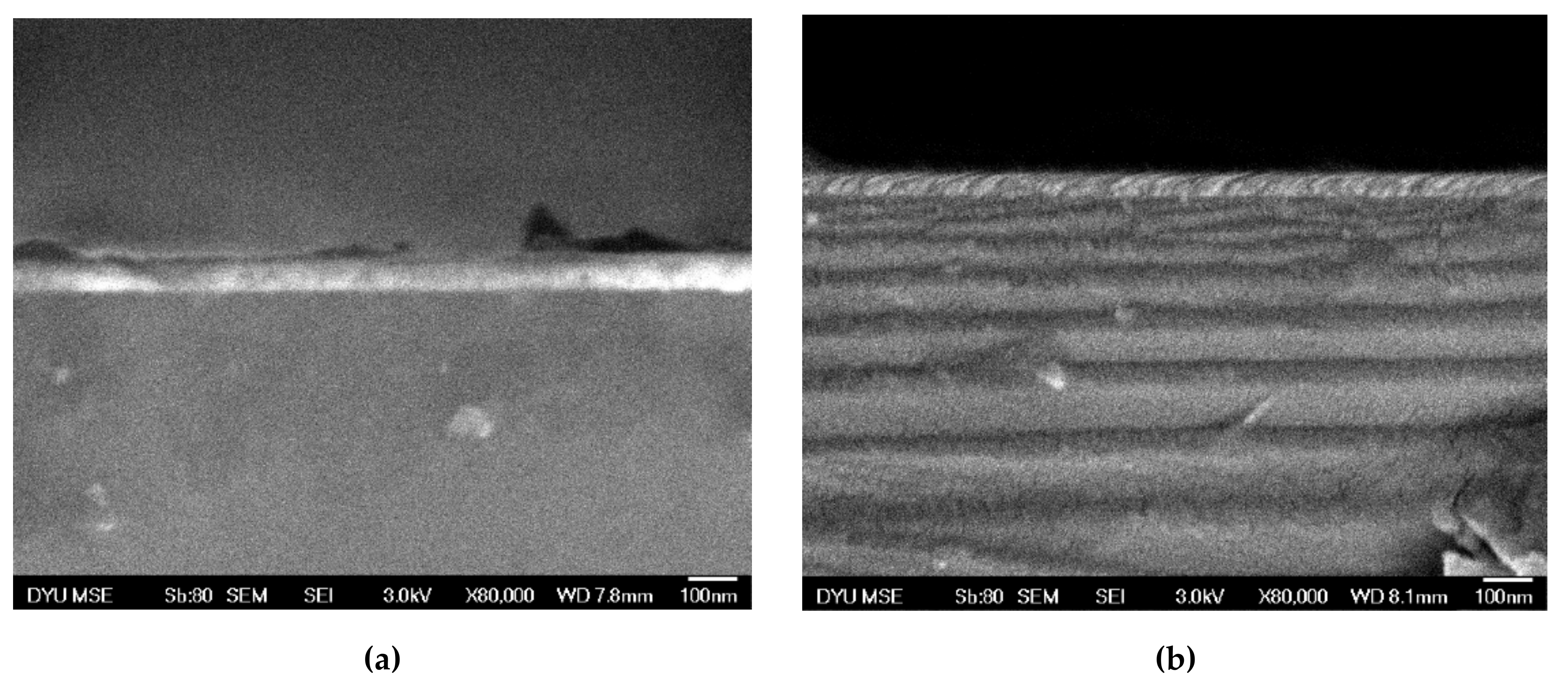
Figure 1a–d depicts the XRD patterns of Co40Fe40Y20 nanofilms with thicknesses ranging from 10 nm to 50 nm, both as-deposited and after annealing at 100, 200, and 300 °C. No characteristic peaks for CoFeY were found, but all oxides were found. For all CoFeY samples, oxide peaks emerged at 2θ = 47.7°, 54.5°, and 56.3°, corresponding to YFeO3 (212), Co2O3 (422), and Co2O3 (511), respectively. However, even though the chamber was evacuated to 10−7 Torr, oxygen may still have been present. Native oxides on the Si (100) substrate and oxygen impurities on the sputtering target both contributed to the establishment of the oxidation peak [26]. Another possible reason for the formation of oxides is the affinity and negative electric degree relationship between the elements [27]. The intensity of all oxide peaks dropped as the thickness of CoFeY increased. The thin layers of the CoFeY were believed to have an oxide thickness that was essentially the same. The strength of each oxide peak dropped as the CoFeY thickness rose. Through a reduction in interference, the waning oxide peak might improve the magnetic and electrical properties.

3.2. SEM Image

Images of the samples taken with a high-resolution cross-sectional field emission scanning electron microscope (SEM) after they had been deposited and annealed at 350 °C are shown in Figure 2a,b. According to the SEM findings, the annealed CoFeY film is more dense than the film in its as-deposited condition. After annealing, the CoFeY thin film thickness somewhat decreased.

3.3. Magnetic Analysis

Low-frequency alternating-current magnetic susceptibility (χac) graphs are depicted in Figure 3a with function logarithmic frequencies at 10–50 nm. Figure 3b–d display the annealed χac which were annealed for one hour at 100, 200 and 300 °C in comparison to a logarithmic frequency range for each thickness of the CoFeY thin film. CoFeY thin films ranged in thickness from 10 to 50 nm, and under each of the four conditions, the amplitude of the χac signal decreased during the course of the high-frequency period.
Figure 4 and Table 1 show the maximum χac values for the four different temperatures and thicknesses of the CoFeY films, respectively. The results showed that as thickness increased, all χac values increased. The maximum value of χac with a thickness of 50 nm was 0.078, 0.095, 0.142, and 0.159 when χac was deposited in its as-deposited state and annealed at 100, 200 and 300 °C. Due to the thickness effect and Y inclusion, the maximum value of χac increased with the thickness of the CoFeY film, which improved the coherence of the spin exchange and grain refining [28]. After annealing, the maximum χac value was greater than the value of the deposited samples. Table 2 shows that the CoFeY films’ ideal resonance frequencies (fres) were in the low-frequency region of 50–100 Hz, indicating that χac had the greatest spin sensitivity at this frequency. The conclusion that the film is acceptable for employment as a low-frequency magnetic recording medium may be drawn from the fact that the fres was less than 100 Hz.

3.4. Electrical Properties

The resistivity of the CoFeY films in the four conditions is depicted in Figure 5a at various thicknesses. The sheet resistance of CoFeY films at various temperatures and thicknesses is depicted in Figure 5b. Accordingly, thinner films showed lower resistivities and sheet resistance amplitudes. In direct proportion to the rise in film thickness, the resistivity and sheet resistance decreased. The electronic conductivity was enhanced by increasing the thickness of the grain size and reducing the obstacles impeding electron migration [29,30].

3.5. Surface Energy and Adhesion Evaluation

Figure 6a–d show the results of the contact-angle measurements using DI water and glycerol (d). The droplets were seen to be virtually spherical in all circumstances and the contact angle was less than 90°. The film’s hydrophilicity and wettability were both good, according to this finding. The data suggest that the contact angle reduced as the annealing temperature rose, which is a logical inference. Similar to C60 and ZnO materials, it displays this behavior [31,32,33]. This discovery was mostly caused by the increased crystallization that occurred during the annealing process. Surface energy and adhesion are important factors to take into account when using CoFeY films as seed or buffer layers. Higher liquid absorption and smaller contact angles are produced by higher surface energy. The hydrophilicity of the layer on the Si (100) substrate was demonstrated by the adhesion effectiveness and contact angle, both of which were smaller than 90°.
Figure 7 displays the surface energy of the CoFeY films for each situation. The film that had been annealed had more surface energy than the film that had just been deposited. A layer that was 40 nm thick and annealed at 300 °C had the highest surface energy at 31.1 mJ/mm2. Higher surface energy results in stronger film adhesion. According to the aforementioned results, all samples had contact angles that were lower than 90°, indicating that they were all hydrophilic films with good wetting capabilities. In addition, there was evidence of a strong correlation between the surface energy and the contact angle. The area and volume of liquid absorbed increased and the contact angles decreased proportionally when the surface free energy was high [34].

3.6. Hardness and Young’s Modulus

The hardness is displayed in four different situations in Figure 8a. Initial-coating hardness values of 13.5 and 16.55 GPa, respectively, were found for films that were 10 and 50 nm. At 100 °C, the hardness of the 10-nm and 50-nm-thick films was 13.98 and 16.67 GPa. For the 10-nm and 50-nm thick films, the hardness was 13.38 GPa and 16.35 GPa at 200 °C and 14.00 GPa and 16.27 GPa at 300 °C, respectively. An increasing trend in hardness was observed with the increasing film thickness, and the maximum value was observed at 100 °C for the film with a thickness of 50 nm. Figure 8b depicts a graph of the Young’s modulus of the CoFeY films, which exhibits an increasing trend with increasing thickness that progressively leveled out, with a maximum value of 235.9 GPa for the 50 nm thick as-deposited film. The experimental results revealed that the hardness and elastic modulus of the Si (100) substrate did not vary considerably with temperature; nevertheless, when the film thickness grew, the hardness and elastic modulus of the Si (100) substrate increased dramatically [35,36].

4. Conclusions

The typical CoFeY alloy peaks were not immediately visible using XRD, and the majority of them appeared to be amorphous. Oxides may be produced by improper sample storage or by the oxidation of the original alloy target. The affinity and negative electric degree relationship between the elements is another potential explanation. The χac value was decreased at the high-frequency period, as evidenced by the results of the ac susceptibility. The highest χac value, 0.159, was observed in a CoFeY film that was 50 nm thick and heated to 300 °C. The maximum value of χac increases as the thickness of the CoFeY film increases due to the thickness effect and the addition of Y, which improved the coherence of the spin exchange and grain refinement. The improved exchange coupling, which led to a rise in the χac value, was the main factor in the Co40Fe40Y20 films’ increase in χac value after annealing. The optimal resonance frequency range for getting the maximum χac value was between 50 and 100 Hz. Furthermore, the electronic conductivity was improved by increasing the grain-size thickness and removing obstacles to electron migration. Hydrophilicity was apparent because none of the films had contact angles greater than 90°. With an increase in annealing temperature, the contact angle decreases. As annealing temperatures rose, the surface energy of the Co40Fe40Y20 films rose as well. After 300 °C annealing, the greatest surface energy for a 40 nm thick film was 31.1 mJ/mm2. The results of the nanomechanical analysis demonstrated that the temperature had little effect on the elastic modulus and hardness. The maximum hardness was determined to be 16.67 GPa at a thickness of 50 nm at 100 °C, and both the hardness and Young’s modulus showed an upward trend with increasing thickness. Due to the high χac value, strong adhesion, favorable nanomechanical properties, and low resistivity, it was discovered that the optimal conditions were at 50 nm with annealing at 300 °C.

Author Contributions

Conceptualization, W.-J.L., Y.-H.C., C.-C.C., Y.-T.C. and S.-L.O.; Methodology, Y.-T.C., Y.-C.L., S.-L.O., S.-Y.L.; Validation and formal analysis, Y.-T.C. and P.-W.C.; Investigation, Y.-T.C. and W.-J.L.; Resources, Y.-T.C.; Writing—original draft preparation, Y.-T.C.; Writing—review and editing, Y.-T.C. and W.-J.L.; Supervision, Y.-T.C. and Y.-H.C.; Project administration, C.-C.C. and Y.-T.C.; Funding acquisition, W.-J.L., Y.-H.C. and C.-C.C. All authors have read and agreed to the published version of the manuscript.

Funding

This work was supported by the National Science Council, under Grant No. MOST 110-2221-E-992-054-MY3, MOST108-2221-E-224-015-MY3, MOST105-2112-M-224-001, and National Yunlin University of Science and Technology, under Grant No. 112T01.

Institutional Review Board Statement

Not applicable.

Informed Consent Statement

Not applicable.

Data Availability Statement

Not applicable.

Conflicts of Interest

The authors declare that there is no conflict of interests regarding the publication of this paper. The funders had no role in the design of the study; in the collection, analyses, or interpretation of data; in the writing of the manuscript, or in the decision to publish the results.

References

  1. Scheunert, G.; Heinonen, O.; Hardeman, R.; Lapicki, A.; Gubbins, M.; Bowman, R.M. A review of high magnetic moment thin films for microscale and nanotechnology applications. Appl. Phys. Rev. 2016, 3, 011301. [Google Scholar] [CrossRef] [Green Version]
  2. Sunder, R.S.; Deevi, S.C. Soft magnetic FeCo alloys: Alloy development, processing, and properties. Int. Mater. Rev. 2005, 50, 157–192. [Google Scholar] [CrossRef]
  3. Ikeda, S.; Tagawa, I.; Uehara, Y.; Kubomiya, T.; Kane, J.; Kakehi, M.; Chikazawa, A. Write heads with pole tip consisting of high-Bs FeCoAlO films. IEEE Trans. Magn. 2002, 38, 2219–2221. [Google Scholar] [CrossRef]
  4. Zhang, H.; Tang, X.; Wei, R.; Zhu, S.; Yang, J.; Song, W.; Dai, J.; Zhu, X.; Sun, Y. Microstructure refinement and magnetization improvement in CoFe thin films by high magnetic field annealing. J. Alloys Compd. 2017, 729, 730–734. [Google Scholar] [CrossRef]
  5. Gould, H.L.B.; Wenny, D.H. Supermendur: A new rectangular-loop magnetic material. Electr. Eng. 1957, 76, 208–211. [Google Scholar] [CrossRef]
  6. Sakita, A.M.P.; Passamani, E.C.; Kumar, H.; Cornejo, D.R.; Fugivara, C.S.; Noce, R.D.; Benedetti, A.V. Influence of current density on crystalline structure and magnetic properties of electrodeposited Co-rich CoNiW alloys. Mater. Chem. Phys. 2013, 141, 576–581. [Google Scholar] [CrossRef]
  7. Mehriz, S.; Sohi, M.H.; Ebrahimi, S.A.S. Study of microstructure and magnetic properties of electrodeposited nanocrystalline CoFeNiCu thin films. Surf. Coat. Technol. 2011, 205, 4757–4763. [Google Scholar] [CrossRef]
  8. Kockar, H.; Ozergin, E.; Karaagac, O.; Alper, M. Characterisations of CoFeCu films: Influence of Fe concentration. J. Alloys Compd. 2014, 586, S326–S330. [Google Scholar] [CrossRef]
  9. Liu, J.; Wu, Q.; Yan, H.; Zhong, S.; Huang, Z. Effect of Trace Yttrium Addition and Heat Treatmenton the Microstructure and Mechanical Properties of As-Cast ADC12 Aluminum Alloy. Appl. Sci. 2019, 9, 53. [Google Scholar] [CrossRef] [Green Version]
  10. Li, D.-Q.; Zhou, L.-X.; Zhu, K.-J.; Gu, J.; Zheng, S.-H. Isothermal oxidation behavior of scandium and yttrium co-doped B2-type iron-aluminum intermetallics at elevated temperature. Rare Met. 2018, 37, 690–698. [Google Scholar] [CrossRef]
  11. Mihajlovic, J.; Rinklebe, J. Rare earth elements in German soils-A review. Chemosphere 2018, 205, 514–523. [Google Scholar] [CrossRef] [PubMed]
  12. Baulin, O.; Bugnet, M.; Fabrègue, D.; Lenain, A.; Gravier, S.; Cazottes, S.; Kapelski, G.; Ovanessian, B.T.; Balvay, S.; Hartmann, D.J.; et al. Improvement of mechanical, thermal, and corrosion properties of Ni- and Al-free Cu–Zr–Ti metallic glass with yttrium addition. Materialia 2018, 1, 249–257. [Google Scholar] [CrossRef]
  13. Liu, Z.; Qian, D.; Zhao, L.; Zheng, Z.; Gao, X.; Ramanujan, R. Enhancing the coercivity, thermal stability and exchange coupling of nano-composite (Nd, Dy, Y)–Fe–B alloys with reduced Dy content by Zr addition. J. Alloys Compd. 2014, 606, 44–49. [Google Scholar] [CrossRef]
  14. Courcot, E.; Rebillat, F.; Teyssandier, F.; Pouillerie, C.L. Stability of rare earth oxides in a moist environment at elevated temperatures—Experimental and thermodynamic studies part II: Comparison of the rare earth oxides. J. Eur. Ceram. Soc. 2010, 30, 1911–1917. [Google Scholar] [CrossRef]
  15. Aghazadeh, M.; Barmi, A.A.M.; Shiri, H.M. Cathodic electrodeposition and characterization of nanostructured Y2O3 from chloride solution part I: Effect of current density. Russ. J. Electrochem. 2013, 49, 344–353. [Google Scholar] [CrossRef]
  16. Yan, F.; Liu, Z.T.; Liu, W.T. The preparation and properties of Y2O3/AlN anti-reflection films on chemical vapor deposition diamond. Thin Solid Film. 2011, 520, 734–738. [Google Scholar] [CrossRef]
  17. Pearce, S.J.; Parker, G.J.; Charlton, M.D.B.; Wilkinson, J.S. Structural and optical properties of yttrium oxide thin films for planar wave guiding application. J. Vac. Sci. Technol. A 2010, 28, 1388–1392. [Google Scholar] [CrossRef] [Green Version]
  18. Hao, C.; Zhang, D.; Jin, L.; Zhang, H.; Jia, N.; Tang, X. Compositional dependence of magnetic and high frequency properties of nanogranular CoFe-Yttrium-doped Zirconia films. J. Alloys Compd. 2015, 648, 270–275. [Google Scholar] [CrossRef]
  19. Dunn, I.H.; Jacobo, S.E.; Bercoff, P.G. Structural and magnetic influence of yttrium-for-iron substitution in cobalt ferrite. J. Alloys Compd. 2017, 691, 130–137. [Google Scholar] [CrossRef]
  20. Liu, W.J.; Chang, Y.H.; Chen, Y.T.; Tsai, D.Y.; Lu, P.X.; Lin, S.H.; Wu, T.H.; Chi, P.W. Effect of Yttrium Addition on Structure and Magnetic Properties of Co60Fe20Y20 Thin Films. Materials 2021, 14, 6001. [Google Scholar] [CrossRef]
  21. Tishkevich, D.; Grabchikov, S.; Zubar, T.; Vasin, D.; Trukhanov, S.; Vorobjova, A.; Yakimchuk, D.; Kozlovskiy, A.; Zdorovets, M.; Giniyatova, S.; et al. Early-Stage Growth Mechanism and Synthesis Conditions-Dependent Morphology of Nanocrystalline Bi Films Electrodeposited from Perchlorate Electrolyte. Nanomaterials 2020, 10, 1245. [Google Scholar] [CrossRef] [PubMed]
  22. Zubar, T.; Fedosyuk, V.; Tishkevich, D.; Panasyuk, M.; Kanafyev, O.; Kozlovskiy, A.; Zdorovets, M.; Michels, D.; Lyakhov, D.; Trukhanov, A. Mechanisms of elastoplastic deformation and their effect on hardness of nanogranular Ni-Fe coatings. Int. J. Mech. Sci. 2022, 215, 106952. [Google Scholar] [CrossRef]
  23. Ma, K.; Chung, T.S.; Good, R.J. Surface energy of thermotropic liquid crystalline polyesters and polyesteramide. J. Polym. Sci. 1998, 36, 2327–2337. [Google Scholar] [CrossRef]
  24. Owens, D.K.; Wendt, R.C. Estimation of the surface free energy of polymers. J. Appl. Polym. Sci. 1969, 13, 1741–1747. [Google Scholar] [CrossRef]
  25. Kaelble, D.H.; Uy, K.C. A Reinterpretation of organic liquid-polytetrafluoroethylene surface interactions. J. Adhens. 1970, 2, 50–60. [Google Scholar] [CrossRef]
  26. Liu, W.J.; Chang, Y.H.; Chen, Y.T.; Chiang, Y.C.; Liu, Y.C.; Wu, T.H.; Chi, P.W. Effect of annealing on the structural, magnetic, surface energy of CoFeBY films on Si (100) substrate. Materials 2021, 14, 987. [Google Scholar] [CrossRef]
  27. Lan, T.T.B.; Chang, C.-W.; Kuo, M.-R.; Sun, A.A.-C. Strengthening the magnetic properties of Pr-Fe-B thin films using biased substrate. Colloids Surf. A 2022, 646, 128925. [Google Scholar]
  28. Jen, S.U.; Yao, Y.D.; Chen, Y.T.; Wu, J.M.; Lee, C.C.; Tsai, T.L.; Chang, Y.C. Magnetic and electrical properties of amorphous CoFeB films. J. Appl. Phys. 2006, 99, 053701. [Google Scholar] [CrossRef] [Green Version]
  29. Wang, C.M.; Hsieh, J.H.; Li, C. Electrical and piezoresistive properties of TaN-Cu nanocomposite thin films. Thin Solid Film. 2004, 469–470, 455–459. [Google Scholar] [CrossRef]
  30. Kazi, I.H.; Wild, P.M.; Moore, T.N.; Sayer, M. The electromechanical behavior of nichrome(80/20wt.%) film. Thin Solid Film. 2003, l433, 337–343. [Google Scholar] [CrossRef]
  31. Kitamura, M.; Kuzumoto, Y.; Kamura, M.; Aomori, S.; Na, J.H.; Arakawa, Y. Low-voltage-operating fullerene C60 thin-film transistors with various surface treatments. Phys. Status Solidi (C) 2008, 5, 3181–3183. [Google Scholar] [CrossRef]
  32. Beaini, S.S.; Kronawitter, C.X.; Carey, V.P.; Mao, S.S. ZnO deposition on metal substrates: Relating fabrication, morphology and wettability. J. Appl. Phys. 2013, 113, 184905. [Google Scholar] [CrossRef]
  33. Yao, G.; Zhang, M.; Lv, J.; Xu, K.; Shi, S.; Gong, Z.; Tao, J.; Jiang, X.; Yang, L.; Cheng, Y.; et al. Effects of Electrodeposition Electrolyte Concentration on Microstructure, Optical Properties andWettability of ZnO Nanorods. J. Electrochem. Soc. 2015, 162, D300–D304. [Google Scholar] [CrossRef]
  34. Kong, S.H.; Okamoto, T.; Nakagawa, S. [Ni-Fe/Si] double seedlayer with low surface energy for Fe-Co-B soft magnetic underlayer with high Hk for perpendicular magnetic recording media. IEEE Trans. Magn. 2004, 40, 2389–2391. [Google Scholar] [CrossRef]
  35. Zhu, J.; Han, J.; Liu, A.; Meng, S.; Jiang, C. Mechanical properties and Raman characterization of amorphous diamond films as a function of film thickness. Surf. Coat. Technol. 2007, 201, 6667–6669. [Google Scholar] [CrossRef]
  36. Liu, W.J.; Chang, Y.H.; Fern, C.L.; Chen, Y.T.; Jhou, T.Y.; Chiu, P.C.; Lin, S.H.; Lin, K.W.; Wu, T.H. Annealing Effect on the contact angle, surface energy, electric property, and nanomechanical characteristics of Co40Fe40W20 thin films. Coatings 2021, 11, 1268. [Google Scholar] [CrossRef]
Figure 1. Patterns produced using XRD. (a) RT, (b) after 100 °C annealing, (c) after 200 °C annealing, and (d) after 300 °C annealing.
Coatings 13 00137 g001aCoatings 13 00137 g001b
Figure 2. Cross-sectional SEM images of CoFeY at 40 nm. (a) RT and (b) annealed at 350 °C.
Coatings 13 00137 g002
Figure 3. The relationship between the χac and frequency. (a) RT, (b) after 100 °C annealing, (c) after 200 °C annealing, and (d) after 300 °C annealing.
Coatings 13 00137 g003aCoatings 13 00137 g003b
Figure 4. Maximum χac of CoFeY films under four conditions.
Coatings 13 00137 g004
Figure 5. (a) The resistivity and (b) the sheet resistance of CoFeY films.
Coatings 13 00137 g005
Figure 6. Contact angles of the CoFeY following four situations: (a) RT, (b) after annealing at 100 °C, (c) after annealing at 200 °C, and (d) after annealing at 300 °C.
Coatings 13 00137 g006aCoatings 13 00137 g006b
Figure 7. Surface energy of CoFeY films under four conditions.
Coatings 13 00137 g007
Figure 8. (a) Hardness and (b) Young’s modulus of CoFeY films.
Coatings 13 00137 g008
Table 1. Maximum χac value under four conditions.
Film ThicknessRT
Maximum
(a.u.)
100 °C
Maximum
(a.u.)
200 °C
Maximum
(a.u.)
300 °C
Maximum
(a.u.)
10 nm0.03450.03480.06310.0858
20 nm0.03940.04620.07110.0924
30 nm0.05590.05640.0920.1223
40 nm0.06270.06930.12380.1374
50 nm0.07800.09590.14290.1594
Table 2. Resonance frequency that works best for films of different thicknesses.
Film ThicknessRT
Frequency(Hz)
100
Frequency(Hz)
200 °C
Frequency(Hz)
300 °C
Frequency(Hz)
10 nm5010050100
20 nm1001005050
30 nm50505050
40 nm505010050
50 nm50505050
Disclaimer/Publisher’s Note: The statements, opinions and data contained in all publications are solely those of the individual author(s) and contributor(s) and not of MDPI and/or the editor(s). MDPI and/or the editor(s) disclaim responsibility for any injury to people or property resulting from any ideas, methods, instructions or products referred to in the content.

