
Investigation of Electrochemical Characteristics and Interfacial Contact Resistance of TiN-Coated Titanium as Bipolar Plate in Polymer Electrolyte Membrane Fuel Cell

Abstract
:1. Introduction
2. Experimental Procedure
2.1. Sample Preparation
2.2. Characterization of TiN Films
2.3. Electrochemical Experiment
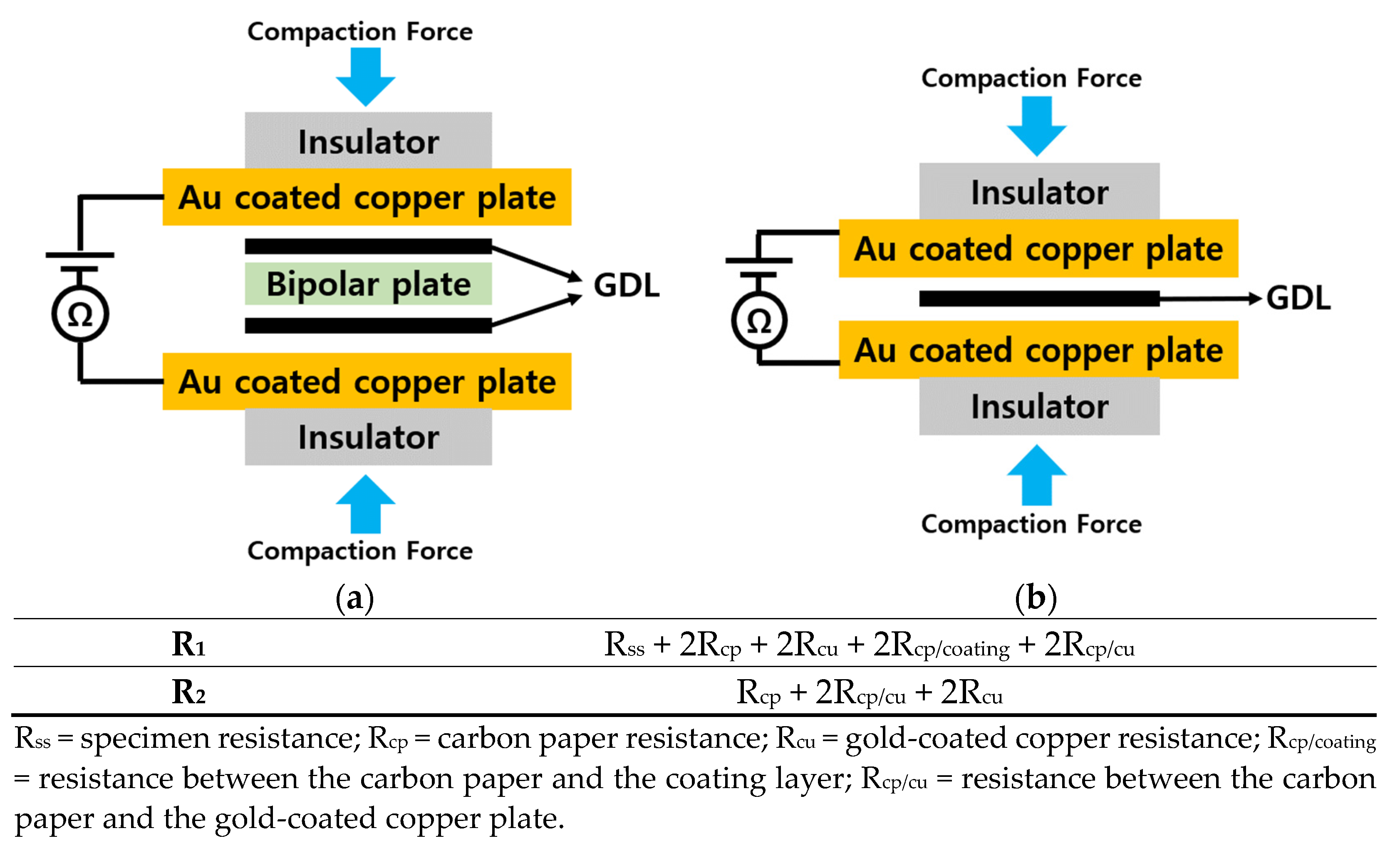
2.4. Measurement of Interfacial Contact Resistance (ICR)
3. Results and Discussion
3.1. Characterization of TiN Films
3.2. Electrochemical Experiments
3.3. ICR Measurement
4. Conclusions
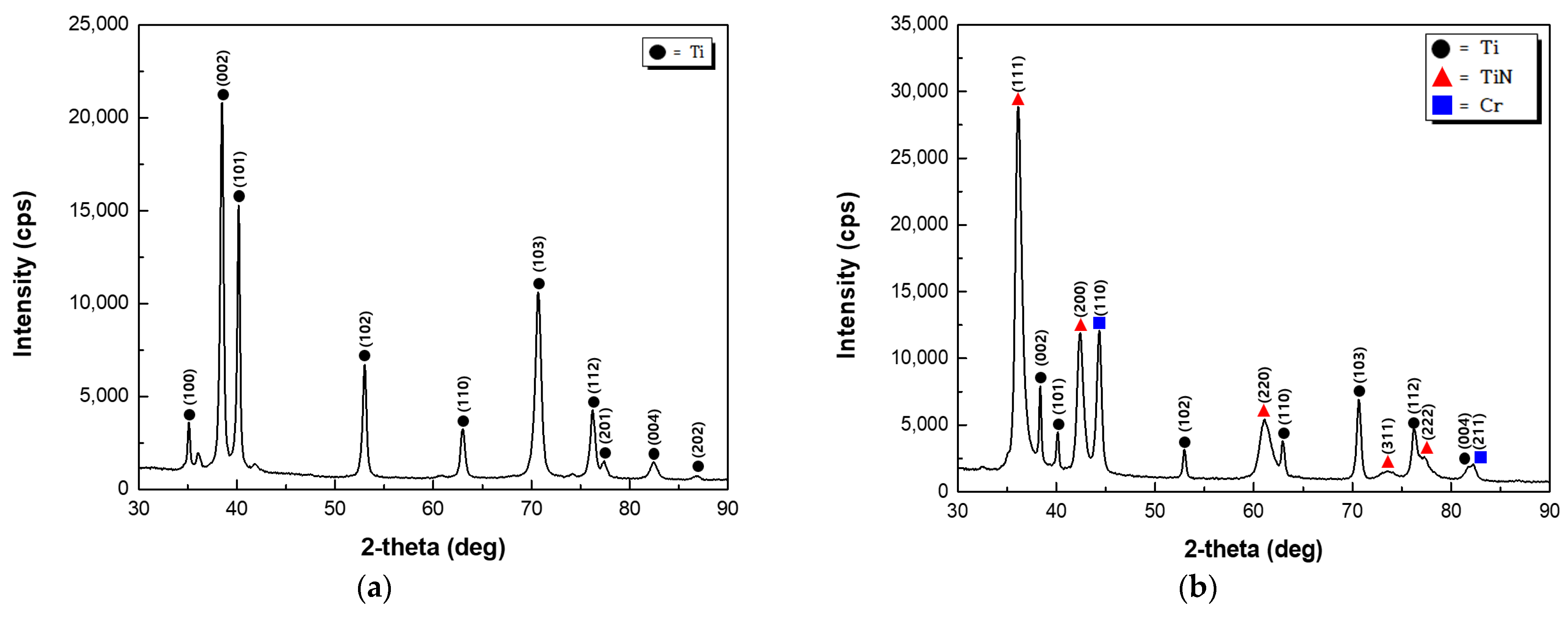
- As the TiN coating layer of the FCC structure was deposited, the peak value of the (111) plane was the largest;
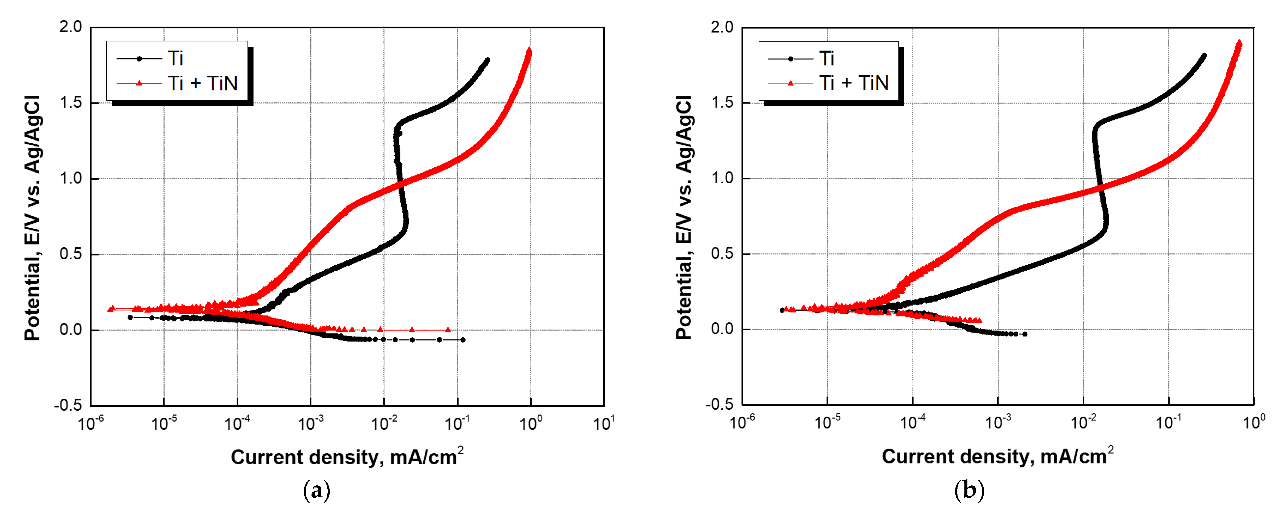
- In the potentiodynamic polarization experiment, an active peak in current density due to corrosion was not observed in the TiN-coated specimen in either the anode or cathode environments. The corrosion current density was less than 1 μA/cm2. In addition, the porosity of the TiN coating layer calculated from the data extracted from the potentiodynamic polarization curve ranged from 0.5% to 1.5%;
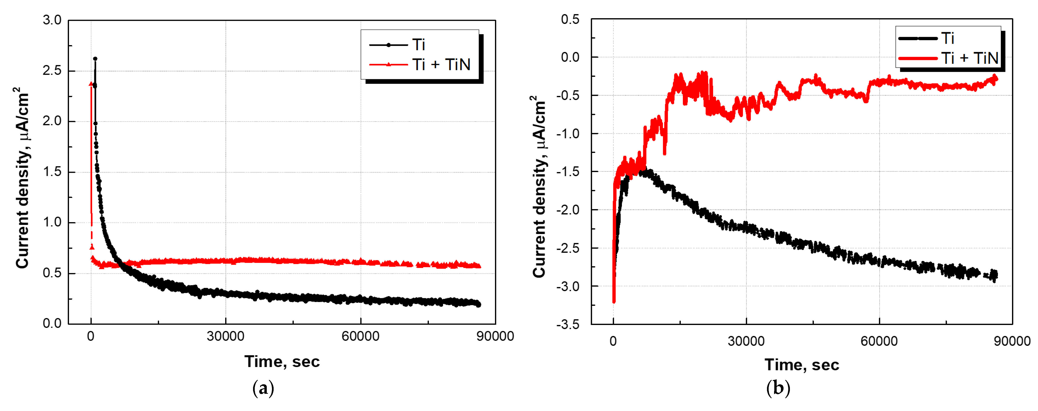
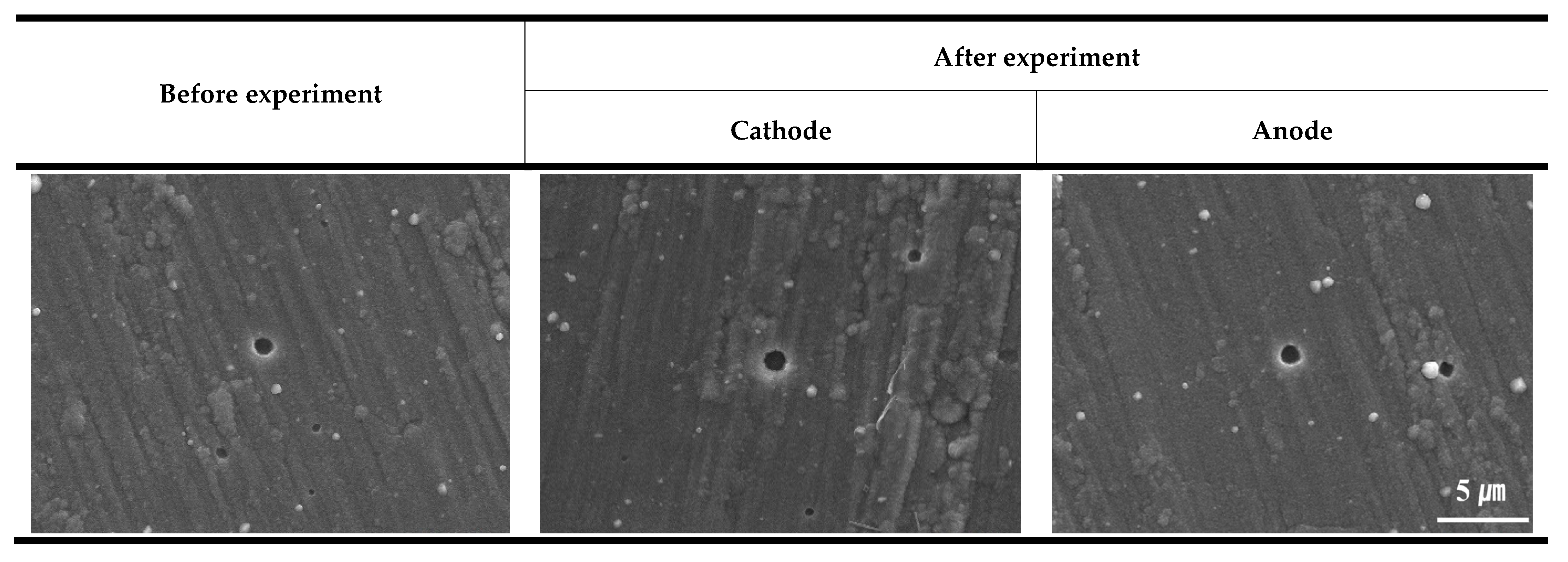
- The TiN-coated specimen exhibited a current density of 1 μA/cm2 or less in both the anode and cathode environments. The surface analysis of the coating layer before and after the potentiostatic corrosion experiment demonstrated that although defects caused by pinholes were observed in the TiN-coated specimen, there was no corrosion damage;
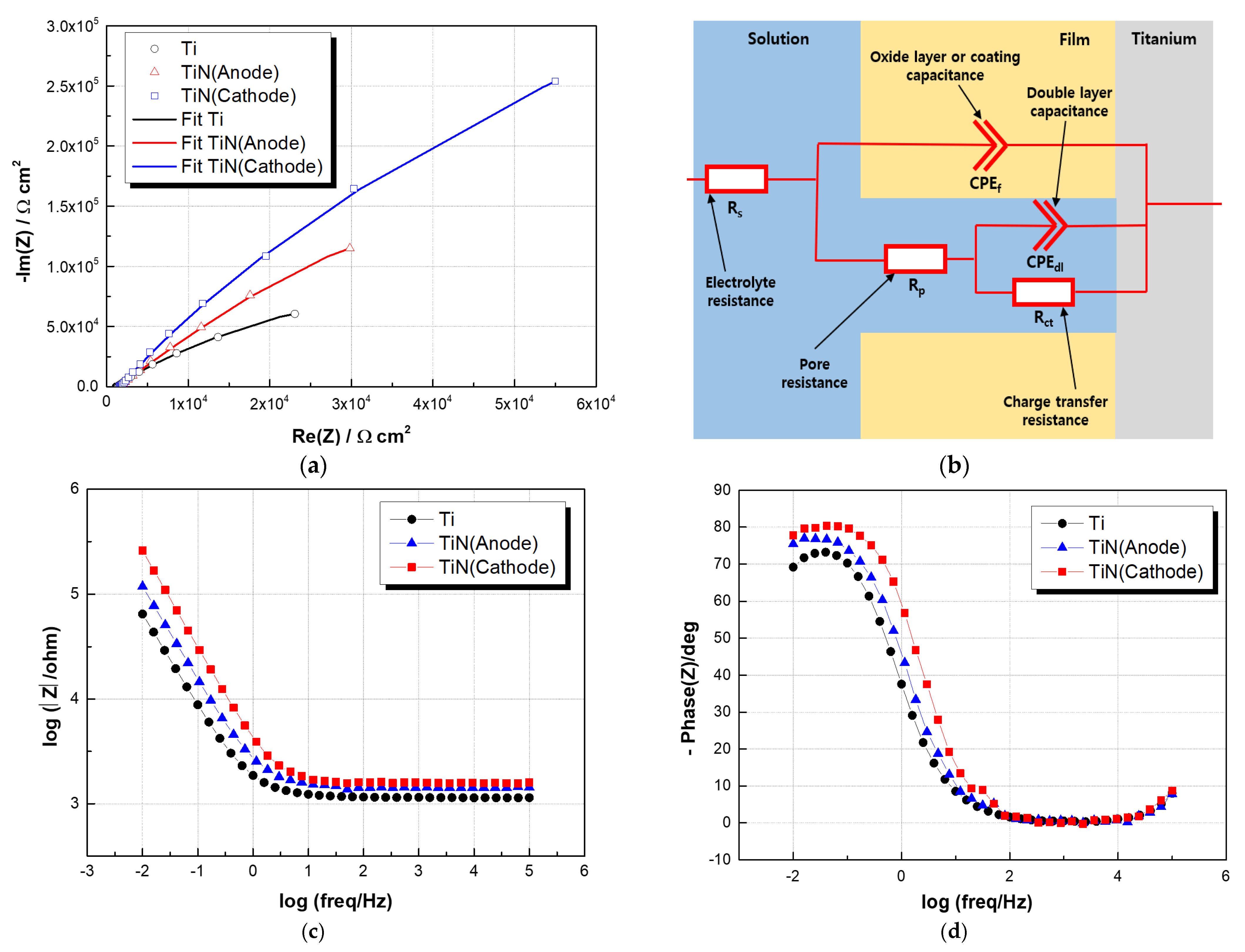
- The EIS analysis showed that the TiN-coated specimen exhibited a higher charge transfer resistance than the titanium substrate, indicating excellent corrosion resistance in a PEMFC environment.
Author Contributions
Funding
Institutional Review Board Statement
Informed Consent Statement
Data Availability Statement
Conflicts of Interest
References
- Sharaf, O.Z.; Orhan, M.F. An overview of fuel cell technology: Fundamentals and applications. Renew. Sustain. Energy Rev. 2014, 32, 810–853. [Google Scholar] [CrossRef]
- Chandan, A.; Hattenberger, M.; El-kharouf, A.; Du, S.; Dhir, A.; Self, V.; Pollet, B.G.; Ingram, A.; Bujalski, W. High temperature (HT) polymer electrolyte membrane fuel cells (PEMFC)—A review. J. Power Sources 2013, 231, 264–278. [Google Scholar] [CrossRef]
- Tawfik, H.; Hung, Y.; Mahajan, D. Metal bipolar plates for PEM fuel cell- A review. J. Power Sources 2007, 163, 755–767. [Google Scholar] [CrossRef]
- Jang, D.S.; Lee, J.J. Corrosion Properties of Carbon-Coated Metallic Bipolar Plate for PEMFC. J. Surf. Sci. Eng. 2015, 48, 82–92. [Google Scholar] [CrossRef] [Green Version]
- Maheshwari, P.H.; Mathur, R.B.; Dhami, T.L. Fabrication of high strength and a low weight composite bipolar plate for fuel cell applications. J. Power Sources 2007, 173, 394–403. [Google Scholar] [CrossRef]
- Hwang, I.U.; Yu, H.N.; Kim, S.S.; Lee, D.G.; Suh, J.D.; Lee, S.H.; Ahn, B.K.; Kim, S.H.; Lim, T.W. Bipolar plate made of carbon fiber epoxy composite for polymer electrolyte membrane fuel cells. J. Power Sources 2008, 184, 90–94. [Google Scholar] [CrossRef]
- Oh, I.H.; Lee, J.B. Corrosion Behaviors of 316L Stainless Steel Bipolar Plate of PEMFC and Measurements of Interfacial Contact Resistance(ICR) between Gas Diffusion Layer(GDL) and Bipolar Plate. Corros. Sci. Technol. 2010, 9, 129–136. [Google Scholar] [CrossRef]
- Davies, D.P.; Adcock, P.L.; Turpin, M.; Rowen, S.J. Stainless steel as a bipolar plate material for solid polymer fuel cells. J. Power Sources 2000, 86, 237–242. [Google Scholar] [CrossRef]
- Li, Z.; Feng, K.; Wang, Z.; Cai, X.; Yao, C.; Wu, Y. Investigation of single-layer and multilayer coatings for aluminum bipolar plate in polymer electrolyte membrane fuel cell. Int. J. Hydrogen Energy 2014, 39, 8421–8430. [Google Scholar] [CrossRef]
- Jin, C.K.; Jeong, M.G.; Kang, C.G. Fabriaction of titanium bipolar plates by rubber forming and performance of single cell using TiN-coated titanium bipolar plates. Int. J. Hydrogen Energy 2014, 39, 21480–24188. [Google Scholar] [CrossRef]
- Cho, E.A.; Jeon, U.S.; Hong, S.A.; Oh, I.H.; Kang, S.G. Performance of a 1kW-class PEMFC stack using TiN-coated 316 stainless steel bipolar plates. J. Power Sources 2005, 142, 177–183. [Google Scholar] [CrossRef]
- Lee, S.J.; Huang, C.H.; Chen, Y.P.; Hsu, C.T. PVD Coated Bipolar Plates for PEM Fuel Cells. J. Fuel Cell Sci. Technol. 2005, 2, 290–294. [Google Scholar] [CrossRef]
- Park, T.S.; Lee, D.W.; Kim, K.H.; Kwon, S.J. Performance assessment of Magnesium Bipolar Plates for Light Weight PEM Fuel Cell. J. Korean Soc. Aeronaut. Space Sci. 2012, 40, 1063–1069. [Google Scholar] [CrossRef]
- Wang, Y.; Northwood, D.O. An investigation on metallic bipolar plate corrosion in simulated anode and cathode environments of PEM fuel cells using potential-pH diagrams. Int. J. Electrochem. Sci. 2006, 1, 447–455. Available online: http://www.electrochemsci.org/papers/1080447.pdf (accessed on 25 September 2006).
- Yi, P.; Zhang, W.; Bi, F.; Peng, L.; Lai, X. Microstructure and properties of a-C films deposited under different argon flow rate on stainless steel bipolar plates for proton exchange membrane fuel cells. J. Power Sources 2019, 410–411, 188–195. [Google Scholar] [CrossRef]
- Wang, H.; Sweikart, M.A.; Turner, J.A. Stainelss steel as bipolar plate material for polymer electroylte membrane fuel cells. J. Power Sources 2003, 115, 243–251. [Google Scholar] [CrossRef]
- Raganya, M.L.; Moshokoa, N.M.; Obadele, B.; Olubambi, P.A.; Machaka, R. The microstructural and mechanical characterization of the β-type Ti-11.1Mo-10.8Nb alloy for biomedical applications. IOP Conf. Ser. Mater. Sci. Eng. 2019, 655, 1–8. [Google Scholar] [CrossRef]
- Syamsai, R.; Rodriguez, J.R.; Pol, V.G.; Le, Q.V.; Vatoo, K.M.; Adil, S.F.; Pandiaraj, S.; Muthumareeswaran, M.R.; Raslan, E.H.; Grace, A.N. Double transition metal MXene (TixTa4-xC3) 2D materials as anodes for Li-ion batteries. Sci. Rep. 2021, 11, 688. [Google Scholar] [CrossRef]
- Wang, L.; Northwood, D.O.; Nie, X.; Housden, J.; Spain, E.; Leyland, A.; Matthews, A. Corrosion properties and contact resistance of TiN, TiAlN and CrN coatings in simulated proton exchange membrane fuel cell environments. J. Power Sources 2010, 195, 3814–3821. [Google Scholar] [CrossRef]
- Li, T.; Yan, Z.; Liu, Z.; Yan, Y.; Chen, Y. Surface microstructure and performance of TiN monolayer film on titanium bipolar plate for PEMFC. Int. J. Hydrogen Energy 2021, 46, 31382–31390. [Google Scholar] [CrossRef]
- Rohendi, D.; Majlan, E.H.; Mohamad, A.B.; Daud, W.R.W.; Kadhum, A.A.H.; Shyuan, L.K. Effects of temperature and backpressure on the performance degradation of MEA in PEMFC. Int. J. Hydrogen Energy 2015, 40, 10960–10968. [Google Scholar] [CrossRef]
- Bong, S.Y.; Kim, Y.R.; Kim, I.; Woo, S.H.; Uhm, S.H.; Lee, J.Y.; Kim, H.S. Graphene supported electrocatalysts for methanol oxidation. Electrochem. Commun. 2010, 12, 129–131. [Google Scholar] [CrossRef]
- Hinds, G.; Brightman, E. Towards more representative test methods for corrosion resistance of PEMFC metallic bipolar plates. Int. J. Hydrogen Energy 2015, 40, 2785–2791. [Google Scholar] [CrossRef]
- Jin, J.; Liu, H.; Zheng, D.; Zhu, Z. Effects of Mo content on the interfacial contact resistance and corrosion properties of CrN coatings on SS316L as bipolar plates in simulated PEMFCs environment. Int. J. Hydrogen Energy 2018, 43, 10048–10060. [Google Scholar] [CrossRef]
- Lee, J.B.; Oh, I.H. Corrosion characteristics and interfacial contact resistance of TiN and CrN coatings deposited by PVD on 316L stainless for polymer electroylte membrane fuel cell bipolar plates. Corros. Sci. Technol. 2013, 12, 171–178. [Google Scholar] [CrossRef] [Green Version]
- Lee, S.H.; Kakati, N.; Maiti, J.; Jee, S.H.; Kalita, D.J.; Yoon, Y.S. Corrosion and electrical properties of CrN-and TiN-coated 316L stainless steel used as bipolar plates for polymer electroylte membrane fuel cells. Thin Solid Film. 2013, 529, 374–379. [Google Scholar] [CrossRef]
- Zhang, D.; Duan, L.; Guo, L.; Tuan, W.H. Corrosion behavior of TiN-coated stainless steel as bipolar plate for proton exchange membrane fuel cell. Int. J. Hydrogen Energy 2010, 35, 3721–3726. [Google Scholar] [CrossRef]
- Tian, R.; Sun, J. Corrosion resistance and interfacial contact resistance of TiN coated 316L bipolar plates for proton exchange membrane fuel cell. Int. J. Hydrogen Energy 2011, 36, 6788–6794. [Google Scholar] [CrossRef]
- Meng, W.; Zhu, H.; Wang, X.; Li, G.; Fan, Y.; Sun, D.; Kong, F. Electrochemical Behavior and Surface Conductivity of C/TiC Nanocomposite Coating on Titanium for PEMFC Bipolar Plate. Metals 2022, 12, 771. [Google Scholar] [CrossRef]
- Hou, K.H.; Lin, C.H.; Ger, M.D.; Shiah, S.W.; Chou, H.M. Analysis of the characterization of water produced from proton exchange membrane fuel cell(PEMFC) under different operating thermal conditions. Int. J. Hydrogen Energy 2012, 37, 3890–3896. [Google Scholar] [CrossRef]
- Ohtsuka, T.; Masuda, M.; Sato, N. Cathodic Reduction of Anodic Oxide Films Formed on Tiatnium. J. Electrochem. Soc. 1987, 134, 2406–2409. [Google Scholar] [CrossRef]
- Xiaoq, L.; Liwei, W.; Lin, F.; Mingyuan, Z.; Lianjun, C.; Zhongyu, C. Understanding the effect of fluoride on corrosion behavior of pure titanium in different acids. Corros. Sci. 2021, 192, 109812. [Google Scholar] [CrossRef]
- Rodrigues, C.A.D.; Bandeira, R.M.; Duarte, B.B.; Filho, G.T.; Roche, V.; Jorge Jr, A.M. Effect of titanium nitride(TiN) on the corrosion behavior of a supermartensitic stainless steel. Mater. Corros. 2018, 70, 28–36. [Google Scholar] [CrossRef] [Green Version]
- Liu, C.; Bi, Q.; Matthews, A. EIS comparison on corrosion performance of PVD TiN and CrN coated mild steel in 0.5N NaCl aqueous solution. Corros. Sci. 2001, 43, 1953–1961. [Google Scholar] [CrossRef]
- Zhang, S.Q.; Zhao, H.Y.; Shu, F.Y.; Wang, G.D.; Liu, B.; Xu, B.S. Study on the corrosion behavior of steel Q315NS heat-affected zone in a HCl solution using electrochemical noise. RSC Adv. 2018, 8, 454–463. [Google Scholar] [CrossRef] [Green Version]
- Ye, C.Q.; Hu, R.G.; Dong, S.G.; Zhang, X.J.; Hou, R.Q.; Du, R.G.; Lin, C.J.; Pan, J.S. EIS analysis on chloride-induced corrosion behavior of reinforcement steel in simulated carbonated concrete pore soultions. J. Electroanal. Chem. 2013, 688, 275–281. [Google Scholar] [CrossRef]
- Asri, N.F.; Husaini, T.; Sulong, A.B.; Majlan, E.H.; Daud, W.R.W. Coating of stainless steel and titanium bipolar plates for anticorrosion in PEMFC: A review. Int. J. Hydrogen Energy 2017, 42, 9135–9148. [Google Scholar] [CrossRef]
- Hedayati, A.; Asghari, S.; Alinoori, A.H. An Investigation on contact resistance and corrosion properties of AISI 316L stainless steel as bipolar plate in proton exchange membrane fuel cell. Iran. J. Hydrog. Fuel Cell 2016, 2, 137–149. [Google Scholar] [CrossRef]


| Fe | C | N | H | O | Ti |
|---|---|---|---|---|---|
| ≤0.20 | ≤0.08 | ≤0.03 | ≤0.015 | ≤0.18 | Bal |
| Process | Source | Ampere (A) | Voltage (V) | Gas Flow (sccm) | Time (min) | Bias (-V) | Temp (°C) |
|---|---|---|---|---|---|---|---|
| Etching | Ion beam | 0.1~0.5 | 800~2000 | 50~80 (Ar) | 100~150 | 50~200 | 250 |
| Cr Buffer layer | Sputter | 4~8 | 300~500 | 80~130 (Ar) | 30~80 | 50~200 | |
| TiN | Arc | 16~18 | 30~90 | 300~500 (N2) | 70~100 | 50~200 |
| Characteristic | Units | 2020 Targets |
|---|---|---|
| Corrosion, anode | μA/cm2 | <1 and no active peak |
| Corrosion, cathode | μA/cm2 | <1 |
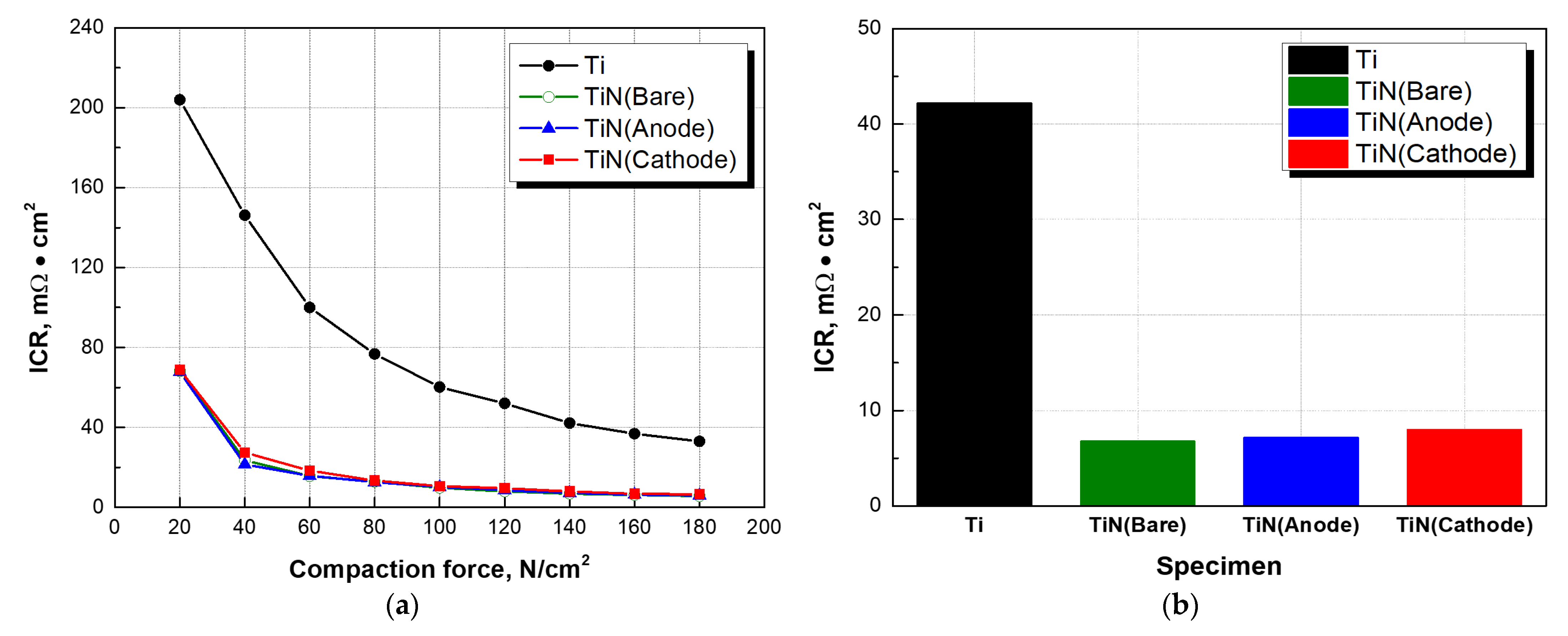
| Areal specific resistance | mΩ·cm2 | <10 |
| - | Specimen | Icorr (μA/cm2) | Ecorr (mV) | βa (V/dec) | βc (V/dec) | Rp (× 103 Ω cm2) | Porosity (%) |
|---|---|---|---|---|---|---|---|
| Cathode | Ti | 0.180 | 82.764 | 0.3251 | 0.1147 | 204.53 | - |
| TiN-coated | 0.070 | 138.280 | 0.2039 | 0.1126 | 449.976 | 1.5 | |
| Anode | Ti | 0.111 | 124.9 | 0.2974 | 0.1575 | 402.799 | - |
| TiN-coated | 0.035 | 125.1 | 0.4867 | 0.0695 | 754.489 | 0.5 |
| - | Rs (× 103 Ω cm2) | CPEf (× 10−3 Ω−1 cm−2 sn) | nf | Rp (× 106 Ω cm2) | Rct (× 103 Ω cm2) | CPEdl (× 10−3 Ω−1 cm−2 sn) | ndl |
|---|---|---|---|---|---|---|---|
| Ti | 1.188 | 0.173 | 0.86 | 0.480 | 41.022 | 0.863 | 0.71 |
| Ti + TiN (Cathode) | 1.652 | 0.049 | 0.92 | 2.893 | 443.09 | 437.3 | 0.94 |
| Ti + TiN (Anode) | 1.491 | 0.098 | 0.88 | 2.986 | 122.79 | 301.7 | 0.80 |
| Specimen | ICR(mΩ·cm2) | |||||||||
|---|---|---|---|---|---|---|---|---|---|---|
| 20 N/cm2 | 40 N/cm2 | 60 N/cm2 | 80 N/cm2 | 100 N/cm2 | 120 N/cm2 | 140 N/cm2 | 160 N/cm2 | 180 N/cm2 | ||
| Ti substrate | 204.0 | 146.2 | 100.0 | 76.8 | 60.2 | 52.0 | 42.2 | 36.8 | 33.0 | |
| TiN- coated titanium | Bare | 68.2 | 23.6 | 15.6 | 12.8 | 9.8 | 8.0 | 6.8 | 6.2 | 5.6 |
| Anode | 67.8 | 21.4 | 15.8 | 12.6 | 10.2 | 8.6 | 7.2 | 6.4 | 6.0 | |
| Cathode | 68.8 | 27.4 | 18.4 | 13.4 | 10.6 | 9.8 | 8.0 | 6.8 | 6.6 | |
Disclaimer/Publisher’s Note: The statements, opinions and data contained in all publications are solely those of the individual author(s) and contributor(s) and not of MDPI and/or the editor(s). MDPI and/or the editor(s) disclaim responsibility for any injury to people or property resulting from any ideas, methods, instructions or products referred to in the content. |
© 2023 by the authors. Licensee MDPI, Basel, Switzerland. This article is an open access article distributed under the terms and conditions of the Creative Commons Attribution (CC BY) license (https://creativecommons.org/licenses/by/4.0/).
Share and Cite
Heo, H.-S.; Kim, S.-J. Investigation of Electrochemical Characteristics and Interfacial Contact Resistance of TiN-Coated Titanium as Bipolar Plate in Polymer Electrolyte Membrane Fuel Cell. Coatings 2023, 13, 123. https://doi.org/10.3390/coatings13010123
Heo H-S, Kim S-J. Investigation of Electrochemical Characteristics and Interfacial Contact Resistance of TiN-Coated Titanium as Bipolar Plate in Polymer Electrolyte Membrane Fuel Cell. Coatings. 2023; 13(1):123. https://doi.org/10.3390/coatings13010123
Chicago/Turabian StyleHeo, Ho-Seong, and Seong-Jong Kim. 2023. "Investigation of Electrochemical Characteristics and Interfacial Contact Resistance of TiN-Coated Titanium as Bipolar Plate in Polymer Electrolyte Membrane Fuel Cell" Coatings 13, no. 1: 123. https://doi.org/10.3390/coatings13010123