Article

Approach to the Modification of Carbon-Based Composite Conductive Ink for Silicone Keypads

1
College of Materials Science and Engineering, Sichuan University, Chengdu 610065, China
2
Sichuan Shengfa Electronic Technology Co., Ltd., Dazhou 636251, China
3
Jiangsu Pangea Semiconductor Equipment Technologies Co., Ltd., Nantong 226010, China
*
Author to whom correspondence should be addressed.
Coatings 2022, 12(9), 1368; https://doi.org/10.3390/coatings12091368
Submission received: 3 August 2022 / Revised: 14 September 2022 / Accepted: 16 September 2022 / Published: 19 September 2022
(This article belongs to the Section Surface Characterization, Deposition and Modification)

Abstract

:
Carbon-based composite conductive ink (3CI) has some challenges to its properties. Here, combined with the application of 3CI on silicon keypads, a series of studies on the electrical, mechanical and thermal performance of 3CI has been conducted by adding specific concentrations of silver powder, silica powder and SiO2@Ag core-shell particles. The properties of the modified 3CI were characterized by using the four-point probe tester, scanning electron microscope, Rockwell hardness tester, cross-cut tester and laser thermal conductivity analyzer. The experimental results revealed that by adding silver powder with a particle size of 20 microns equivalent to 12% by weight of the 3CI, ink resistance decreased by 76%, from 8.44 kΩ/□ to 2.03 kΩ/□. Meanwhile, adding silica can increase the ink’s tensile strength and thermal diffusivity while improving the adhesion of the 3CI on the silicone rubber. It was worth noting that when the particle size of the SiO2@Ag core-shell particle was smaller than that of the added silver powder, the resistance of the 3CI was further reduced. Finally, a modified 3CI with the adhesion of 4B, a conductivity of about1 kΩ/□, a hardness of 232 HV0.5, and a thermal diffusivity of 0.217 cm2s−1 was achieved experimentally, which provided an experimental basis for the modified 3CI suitable for silicone keypads.

1. Introduction

Because conductive ink is extensively used in silicone keypads, flexible electronic devices [1], radio frequency identification (RFID) systems and many other fields, its performance affects the future direction of printed electronic products [2]. As an essential part of electronic products, conductive silicone keypads have received immense attention, because of their excellent elasticity, tactility, easily decontaminated surfaces, and good anti-aging properties [3]. The silicone keypad’s most widely used conductive layer is carbon-based composite conductive ink (3CI). Its conductive filler is mainly composed of graphite, carbon black, carbon fiber and their mixtures [4,5], which has the advantages of low cost, simple manufacture and good stability. However, the resistivity of amorphous carbon powder and graphite is relatively large. After curing, 3CI has relatively low conductivity (100~102 kΩ/□), poor humidity resistance, significant temperature coefficient (under low voltage, from 20 °C to 40 °C, the resistance increases by nearly two orders of magnitude), and weak adhesion, which can only be used for electronic products with low electrical conductivity. Filling with carbon powder will increase the viscosity of the ink to enhanced interfacial interaction, but will lead to poor dispersibility and difficulty in forming conductive network chains; in addition, due to the unstable layered structure of graphite [6], the contact area and probability between the conductive particles in the 3CI may be reduced, resulting in poor conductivity. A practical method is to provide additional electrical connection bridges by adding metal powder, which can significantly improve the electrical conductivity and durability of the ink [7]. Common metal conductive fillers are silver, copper, platinum and gold [8]. From the perspective of electrical conductivity, the volume resistivity of silver is 1.6 × 10⁻⁶ Ω·cm, copper is 1.7 × 10⁻⁶ Ω·cm and gold is 2.3 × 10⁻⁶ Ω·cm [9]. However, in terms of price, gold is about 25 times more than silver and 8000 times more than copper. Due to the low cost of copper, it is developing rapidly [10]. Yujia Yuan et al. reported a one-step synthesis of a wet chemical method for preparing core-shell nanostructures of copper and silver. Their work showed the thermal stability against oxidation and electrical properties of Cu@Ag core-shell nanoparticles. However, copper is easily oxidized in the air, and the surface treatment of copper particles is not only complicated but also susceptible to losing the electrical characteristics and the thermal stabilities of the Cu@Ag particles [11].
Therefore, inks using silver as the conductive phase have always been the mainstream research and development focus of electronic products requiring high reliability, conductivity and precision of the conductive layer.
However, in order to ensure the excellent electrical conductivity of the ink, the amount of silver powder added is often high, and the particle size and morphology of the silver powder need to be precisely controlled [12], which easily leads to increased cost, low adhesion and weak mechanical strength issues. To address these challenges, numerous research groups have developed alternative additives for silver-containing materials for desired performance and cost savings [13]. Wei Wu et al. presented a facile approach to synthesize a cheaper conductive filler by coating Ag NPs on the surface of carbon, which was dispersed in epoxy resin and organic solvent to prepare a conductive paste [14]. However, the submicron particle size of the C@Ag particles has low mobility and inevitable aggregation problems in the polymer matrix [9], resulting in a lack of electrical and mechanical properties. Due to silicone rubber having a smooth and soft surface, a dielectric constant of less than 2.8, low macromolecular polarity and chemical inertness, the inks are difficult to print firmly on the surface of silicone rubber keypads. Therefore, the adhesion and stretch resistance of the conductive ink directly determines the service life of the keypads.
SiO2 ultrafine powder has high chemical stability, a large surface area, good thermal conductivity, a low coefficient of thermal expansion (0.5 ppm/°C) and the same composition as silica gel xSiO2-yH2O. Separating the SiO2 particles into the carbon-based ink can enhance the adhesion between the ink and silicone [15], optimize the mechanical and thermal properties of the contact area and thus improve the service life of the keypads [16]. However, only adding silica cannot increase the conductivity of the ink. Therefore, SiO2 and Ag were synthesized into SiO2@Ag core-shell composite conductive particles with high electrical conductivity [17], high thermal conductivity and low expansion coefficient. Various methods of preparing the SiO2@Ag composite have been developed, including chemical reduction, micro-emulsion, gel-sol, template, reverse micelle and adsorption [18,19,20,21,22,23]. By introducing the SiO2@Ag composite particles into 3CI, the adhesion between the conductive layer and the keypads will be enhanced while maintaining high conductivity. However, the resistivity of the ink added purely with SiO2@Ag as the conductive particle is still high and cannot meet the requirements of high conductive applications. Hence, it is necessary to introduce Ag powder into the composite ink for electrical control.
To develop a high-performance 3CI, a series of modification measures of the ink have been created in this work. Moreover, the characteristics of the modified ink were also analyzed in detail.

2. Experimental Section

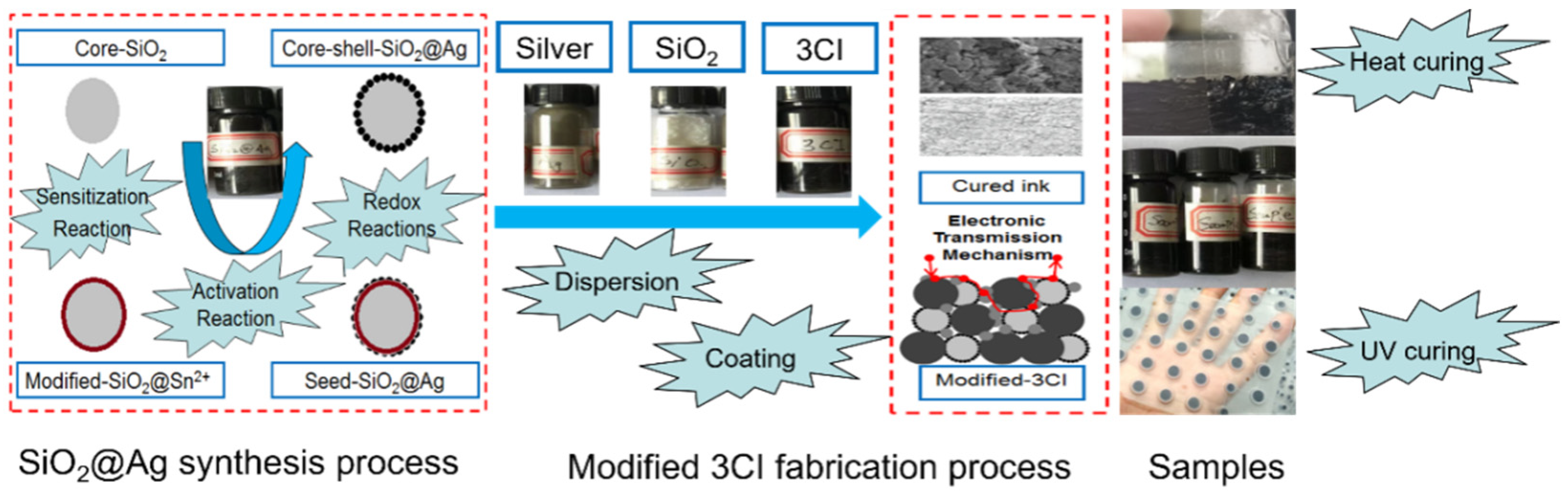
2.1. Preparation of SiO2@Ag Core-Shell Particle

The SiO2@Ag core-shell particle was prepared in this experiment using the chemical silver plating method [24]. In total, 0.1 g of SnCl2 was added to the mixed solution of 0.2 g of SiO2 and 2 mL of anhydrous ethanol that had been ultrasonically dispersed for 15 min. After sealing with tinfoil, the container was put into an electric blast drying oven at 70 °C for 330 min until all the anhydrous ethanol evaporated, and the modified SiO2@Sn2+ powder was obtained through the sensitization reaction. Next, the SiO2@Ag seed solution obtained by the activation reaction of all the modified SiO2@Sn2+ powder and 0.08 of mol/L AgNO3 solution consisting of 5.8 mL of ammonia, 0.0788 g of AgNO3 and 0.0348 g of NaOH was added to the reducing solution consisting of 0.1458 g of anhydrous glucose, 0.1142 g of potassium sodium tartrate and 9 mL of deionized water while stirring. Then this mixture was placed into a centrifuge at 10,000 r for 5 min. After repeated washings with deionized water and pouring off the clear liquid in the upper layer, the bottom sediment was dried at 80 °C in an electric blast dryer to obtain the SiO2@Ag core-shell particle. A schematic diagram of the above process is shown in Figure 1.

2.2. Preparation of Modification of 3CI

Different contents of Ag, SiO2, and SiO2@Ag core-shell particles powder were added to 0.5 g of the ink, respectively. The components are listed in Table 1. After sufficient ultrasonic dispersion and stirring, a modified 3CI was achieved. The ink was applied by spin coating with adjusting the rotational speed from 50 to 1000 rpm to the quartz glass surface and silicone rubber keypad surface shown in Figure 1.
According to the difference in the characteristics of the substrate, the ink coated on the quartz glass was cured in an electric blast drying oven at 140 °C for 1 h. In contrast, the ink painted on the silicone rubber keypads was cured with 254 nm of UV light for 15 min. Before this process, all the inks were baked by using an infrared lamp for 15 min. The thickness of the ink layer in this work was between 20 microns and 3200 microns, which was controllable, relatively uniform and able to be adjusted as needed.

2.3. Characterization

In this work, the thickness of the ink was tested with a profilometer; the composition and morphology of the modified ink and SiO2@Ag core-shell particle were characterized by an X-ray diffractometer (XRD, Shimadzu, Kyoto, Japan) and scanning electron microscope (SEM, Hitachi, Tokyo, Japan); the compressive resistance and adhesion properties of the modified ink coated on the substrate were tested by VTD-512 digital Rockwell hardness tester (Wowei Technology Co., Ltd., Beijing, China) and QFH-A cross-cut tester (Huake Precision Instrument Co., Ltd., Dongguan, China); the electrical conductivity and thermal conductivity of the modified ink were characterized by RTS-9 four-point probe (Guangzhou 4Probes Tech Ltd., Guangzhou, China) tester and LINSEISLFA-1000 laser thermal conductivity analyzer (Linseis Inc, Selb, Germany). The tensile resistance of the modified inks was characterized using an INSTRON-5985 electronic universal material testing machine (AG, Instron, Norwood, MA, USA).

3. Results and Discussion

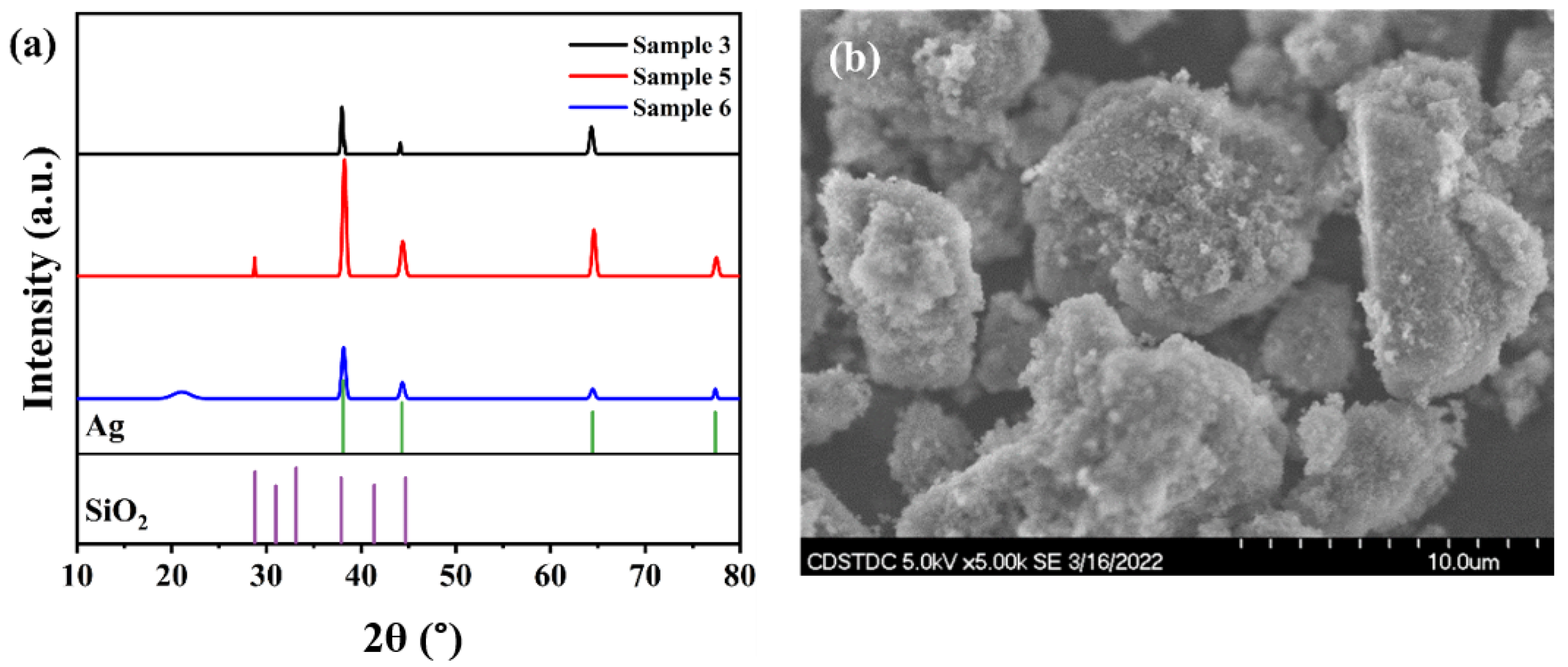
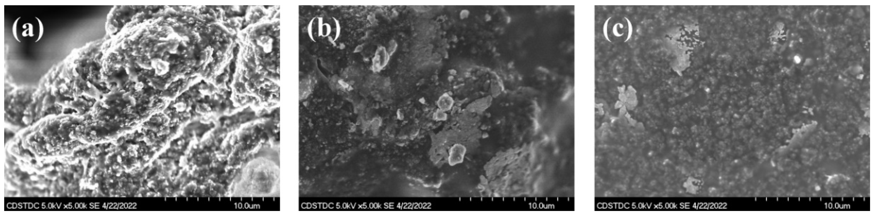
3.1. Structure and Morphology

The XRD diffraction patterns of samples 3, 5 and 6 are shown in Figure 2a. Comparing with the PDF cards of Ag and SiO2 below this picture, the SiO2 peaks of sample 5 at 2θ = 28°, 38° and 44°, sample 3 and sample 6 at 2θ = 38° and 44° can be observed, respectively. Furthermore, the Ag peaks at 2θ = 38°, 44°, 64° and 77° were observed for all three samples. That meant the silver particles obtained by reduction were successfully deposited and coated on the silica surface to form the SiO2@Ag core-shell particle. The SEM surface morphology of samples 3, 5 and 6 are shown in Figure 3. The SiO2 particles of sample 5 with a diameter of about 5 μm can be seen in Figure 3b. Furthermore, its irregular shapes and sharp protrusions can be also discerned. This indicated that adding silica may destroy the original conductive channels of the ink, thereby increasing the resistance of the ink after curing, which was consistent with the later electrical performance tests. Combining the SEM images of Figure 2b and Figure 3a, it can be observed that the sharpness of the SiO2@Ag core-shell particle surface was improved after silver was deposited on the silica surface. This change indicated a better coating effect and more obvious electrical connections between particles. However, the surface condition of the cured ink with the SiO2@Ag core-shell particle was different from sample 5, as depicted in Figure 3b. The whole inks shown in Figure 3a,c have a viscous and dense morphology, especially sample 3. This caused local electrical channels to be blocked by silica that was not fully coated with silver during curing and had a negative effect on the electrical properties of the ink.

3.2. Electrical Properties

The square resistance of samples was measured at the same points shown in Figure 4e. The numbers in Figure 4e represent the five test points respectively. As listed in Table 1, adding silver powder can effectively reduce the resistance of the ink, but the changing trend was different. The resistance of the ink to which silver powder with a diameter of 20 microns was added decreased more than that of the ink to which silver powder with a diameter of 50 nm was added. In contrast, after adding silica powder, the resistance of the ink increased. For example, the resistance of sample 3 increased by 10% compared to that of sample 2, while the resistance of sample 5 increased by 4% compared to that of sample 4. It was worth noting that when the SiO2@Ag core-shell particles were added, the resistance of the ink containing 50 nm of silver powder increased. This was because when the particle size of SiO2@Ag was significantly larger than that of the silver powder, the silver plating on the surface of the silica was incomplete. The exposed silicon dioxide will destroy the original conductive channel, resulting in a decrease in conductivity. This was consistent with the results of the previous SEM analysis. Meanwhile, the resistance of sample 6 added SiO2@Ag core-shell particle with a diameter smaller than that of the silver powder was significantly reduced, only by about 50% of the original value. This was attributed to the easy formation of “electric bridges” [25] between the adjacent silver and the SiO2@Ag core-shell particles.

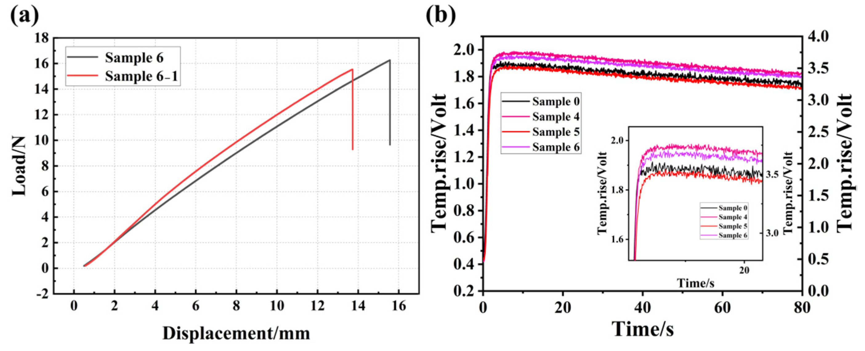
3.3. Mechanical Properties

Figure 4 showed the cross-cut tester adhesion test (paste coated on silicone) according to international test criteria for adhesion (ASTM standard) and the hardness test (paste coated on the copper sheet), and the corresponding test results are listed in Table 2. The adhesion grade of the ink on the silicone rubber keypads with the addition of silver powder remained without appreciable variations at the 3B level, while the adhesion grade of the ink with the addition of silica increased from 3B to 4B. When the 3CI containing silica was coated on the silicone rubber keypads, the diffusion and fusion of silica in the ink and silicone rubber during curing will form additional adhesion channels, which eventually will lead to increased adhesion of the contact surface between the ink and the keypads.
Furthermore, the hardness of sample 0 without any addition was 198 HV0.5 as listed in Table 2, while that of the ink with the addition of silver powder decreased to 168.1 HV0.5. It was worth mentioning that with the addition of silica, the maximum hardness of the cured ink reached 232 Hv0.5, which exceeded the hardness of sample 0. In addition, the hardness of the cured ink with SiO2@Ag decreased to 205 Hv0.5, but it was still higher than sample 0. As shown in Figure 3c, the distribution of fine particles (not SiO2@Ag) on the surface of the cured ink indicated that the hardness-enhancing silica cannot be uniformly distributed throughout the thickness of the ink. That revealed fewer SiO2@Ag particles on the top surface and more SiO2@Ag particles on the bottom, which led to a decrease in the average hardness of sample 6.
The effect of the addition of the SiO2@Ag core-shell particles on the tensile properties of 3CI was investigated as shown in Figure 5a. In this section, sample 6-1 as a comparison was fabricated by adding 0.06 g of silver powder with a particle size of 20 μm and 0.006 g of SiO2@Ag core-shell particle to 0.5 g of the ink. Table 2 lists the test results of the samples on the silicone rubber keypads. Under the condition of using the same pressure, the tensile displacement at fracture (standard) of sample 6-1 was smaller than that of sample 6, indicating that adding SiO2@Ag can improve the ink’s tensile strength. As we know, the addition of the SiO2@Ag core-shell particle was equivalent to introducing a reinforcing material inside the ink, and a closed area was formed between the SiO2@Ag core-shell particles, which can further increase the tensile strength of the cured ink and improve the hardness of the ink. When 3CI with SiO2@Ag core-shell particle was coated on the silicon rubber, the tensile strength of the substrate silicone rubber was also improved due to the enhanced adhesion between the 3CI and the keypad interface, which was consistent with the above description.

3.4. Thermal Properties

The thermal diffusion process of samples 4, 5 and 6 at room temperature are shown in Figure 5b. The inset in the figure is a partial enlarged view. It can be seen that the temperature difference between the upper and lower surfaces of the samples gradually decreased with the increase in time, indicating that heat transfer was carried out inside the sample. As listed in Table 2, the quality of fit value of the curve was more than 95 (quality of fit refers to the consistency between the fitted curve calculated by the instrument and the actual measurement results; if the value is greater than 95, the result is credible). The specimen is subjected to a high-intensity, short-duration radiant energy pulse. The energy of the pulse is absorbed on the front surface of the specimen and the resulting rear-face temperature rise (thermogram) is recorded. The thermal diffusivity value is calculated from the specimen thickness and the time required for the rear-face temperature rise to reach certain percentages of its maximum value. When the thermal diffusivity of the sample is to be determined over a temperature range, the measurement must be repeated at each temperature of interest. For the one-dimensional, adiabatic case, the thermal diffusivity α can be calculated by [26]:
α = 0 . 1388 × d 2 / t 0.5
α is the thermal diffusivity in cm2/s; d is the thickness of test specimen in cm; t0.5 is the time at 50% of the temperature increase, measured at the rear of the specimen in s.
The addition of silver powder reduced the thermal diffusivity of the ink (from 0.184 cm2s−1 to 0.074 cm2s−1), which was a phenomenon that requires great attention for the ink used in high-power environments. With the addition of silica, the thermal diffusivity of the ink increased and exceeded that of the original ink. Furthermore, with the addition of the SiO2@Ag core-shell particle, the thermal diffusivity of the ink decreased to 0.217 cm2s−1, but this value was still higher than that of the original ink. These changes further demonstrated that the addition of the SiO2@Ag core-shell particles could also optimize the thermal conductivity of the ink while optimizing the electrical and mechanical properties.

4. Conclusions

In this work, a method to improve the performance of the ink was proposed in combination with the application of carbon-based composite conductive ink on silicone keypads. That is, the method involves adding silver powder that can increase the conductivity of the ink, silica powder that can increase the thermal conductivity, wear resistance, tensile strength and adhesion, and the SiO2@Ag core-shell particle combining the above advantages of silver powder and silica powder. Through experimental testing and results analysis, it can be concluded that when the particle size of the silica is smaller than that of the silver powder, adding silica powder to the ink can improve the mechanical and thermal properties simultaneously. Furthermore, adding SiO2@Ag core-shell particles can improve the electrical and mechanical properties of the ink. However, it is necessary to control the shape of silica as the core material precisely, to reduce the sharp protrusion on its surface significantly, and then to ensure that the nano-sized silver powder is uniformly coated on the silica surface. The above results provide an experimental basis for developing carbon-based composite conductive inks with special applications by adding silver, SiO2 powders and SiO2@Ag core-shell particles with different particle sizes and shapes.

Author Contributions

Conceptualization, G.Z.; Date curation, G.Z., Y.Z. and X.Y.; Investigation, Q.Z., Y.H., Y.Y. and J.S. Methodology, Y.Y. and G.Z.; Project administration, G.Z., J.T. and H.Z.; Resources, J.T. and H.Z.; Supervision, G.Z.; Validation, Y.Z.; Visualization, J.S.; Writing—original draft, Y.Z. and X.Y.; Writing—review and editing, Y.Z., G.Z., X.Y., Q.Z., Y.H., Y.Y. and J.S. All authors have read and agreed to the published version of the manuscript.

Funding

This work was funded by the Strategic Cooperation Project of Sichuan University-Dazhou (2020CDDZ-04), Sichuan Science and Technology Program (No. 2022YFG0296), Sichuan Demonstration Project of Transfer and Transformation of Scientific and Technological Achievements (2021ZHCG0004) and Cooperation project of Sichuan University-Jiangsu PangeaSemi Semiconductor Equipment Technology Co., Ltd. (21H1155).

Institutional Review Board Statement

Not applicable.

Informed Consent Statement

Not applicable.

Data Availability Statement

Not applicable.

Acknowledgments

We would like to thank Yingming Zhu from the Institute of New Energy and Low-Carbon Technology, Sichuan University, for his help with SEM image capturing and analysis work, and Xiaoshan Zhang from the Central Laboratory of the College of Materials Science and Engineering, Sichuan University, for his help with thermal diffusivity testing and analysis work.

Conflicts of Interest

The authors declare no conflict of interest.

References

  1. Htwe, Y.Z.N.; Mariatti, M. Printed graphene and hybrid conductive inks for flexible, stretchable, and wearable electronics: Progress, opportunities, and challenges. J. Sci. Adv. Mater. Devices 2022, 7, 100435. [Google Scholar] [CrossRef]
  2. Tian, J.; Yuan, J.; Chen, G.; Zhang, W. Preparation and Characterization of Carbon Based Composite Conductive Ink. In Advances in Graphic Communication, Printing and Packaging Technology and Materials; Lecture Notes in Electrical Engineering; Springer: Berlin/Heidelberg, Germany, 2021; pp. 637–645. [Google Scholar] [CrossRef]
  3. Chen, X.; Ma, D.; Wang, S.; Luo, Z.; Wang, X.; Cai, M.; Yang, D. Modeling and analysis on the elastic performance of SMT silicone rubber keypad. In Proceedings of the 2017 18th International Conference on Electronic Packaging Technology (ICEPT), Harbin, China, 16–19 August 2017; pp. 1006–1010. [Google Scholar] [CrossRef]
  4. Mandhakini, M.; Chandramohan, A.; Jayanthi, K.; Alagar, M. Carbon black reinforced C8 ether linked bismaleimide toughened electrically conducting epoxy nanocomposites. Mater. Des. 2014, 64, 706–713. [Google Scholar] [CrossRef]
  5. Leemsuthep, A.; Zakaria, Z.; Lan, D.N.U. Morphology and Conductive Properties of Carbon Black- and Graphite- Filled Conductive E poxy Micro-porous. IOP Conf. Ser. Mater. Sci. Eng. 2020, 957, 012034. [Google Scholar] [CrossRef]
  6. Teplykh, A.E.; Bogdanov, S.G.; Dorofeev, Y.A.; Pirogov, A.N.; Skryabin, Y.N.; Makotchenko, V.G.; Nazarov, A.S.; Fedorov, V.E. Structural state of expanded graphite prepared from intercalation compounds. Crystallogr. Rep. 2006, 51, S62–S66. [Google Scholar] [CrossRef]
  7. Oh, Y.S.; Choi, H.; Lee, J.; Lee, H.; Choi, D.Y.; Lee, S.-U.; Yun, K.-S.; Yoo, S.; Kim, T.-S.; Park, I.; et al. Temperature-Controlled Direct Imprinting of Ag Ionic Ink: Flexible Metal Grid Transparent Conductors with Enhanced Electromechanical Durability. Sci. Rep. 2017, 7, 11220. [Google Scholar] [CrossRef]
  8. Lee, J.Y.; Choi, C.S.; Hwang, K.T.; Han, K.S.; Kim, J.H.; Nahm, S.; Kim, B.S. Optimization of Hybrid Ink Formulation and IPL Sintering Process for Ink-Jet 3D Printing. Nanomaterials 2021, 11, 1295. [Google Scholar] [CrossRef]
  9. Wang, M.; Xu, X.; Ma, B.; Pei, Y.; Ai, C.; Yuan, L. Fabrication of micron-SiO2@nano-Ag based conductive line patterns through silk-screen printing. RSC Adv. 2014, 4, 47781–47787. [Google Scholar] [CrossRef]
  10. Kim, I.; Kim, Y.; Woo, K.; Ryu, E.-H.; Yon, K.Y.; Cao, G.; Moon, J. Synthesis of Oxidation-Resistant Core-Shell Copper Nanoparticles. RSC Adv. 2013, 3, 15169–15177. [Google Scholar] [CrossRef]
  11. Yuan, Y.; Xia, H.; Chen, Y.; Xie, D. One-step synthesis of oxidation-resistant Cu@Ag core-shell nanoparticles. Micro Nano Lett. 2018, 13, 171–174. [Google Scholar] [CrossRef]
  12. Kotthaus, S.; Gunther, B.H.; Hang, R.; Schafer, H. Study of isotropically conductive bondings filled with aggregates of nano-sited Ag-particles. IEEE Trans. Compon. Packag. Manuf. Technol. Part A 1997, 20, 15–20. [Google Scholar] [CrossRef]
  13. Klinkhammer, K.; Nolden, R.; Brendgen, R.; Niemeyer, M.; Zoll, K.; Schwarz-Pfeiffer, A. Coating of Silicone Monofilaments with Elastic Carbon Black-Silver-Silicone Layers and Their Characterization Especially with Regard to the Change of the Electrical Resistance in Dependence on Strain. Polymers 2022, 14, 806. [Google Scholar] [CrossRef]
  14. Wu, W.; Yang, S.; Zhang, S.; Zhang, H.; Jiang, C. Fabrication, characterization and screen printing of conductive ink based on carbon@Ag core-shell nanoparticles. J. Colloid Interface Sci. 2014, 427, 15–19. [Google Scholar] [CrossRef]
  15. Flores, J.C.; Torres, V.; Popa, M.; Crespo, D.; Calderón-Moreno, J.M. Preparation of core-shell nanospheres of silica-silver: SiO2@Ag. J. Non-Cryst. Solids 2008, 354, 5435–5439. [Google Scholar] [CrossRef]
  16. Saber, D.; Abd El-baky, M.A.; Attia, M.A. Advanced Fiber Metal Laminates Filled with Silicon Dioxide Nanoparticles with Enhanced Mechanical Properties. Fibers Polym. 2021, 22, 2447–2463. [Google Scholar] [CrossRef]
  17. Sakthisabarimoorthi, A.; Dhas, S.A.M.B.; Jose, M. Fabrication and nonlinear optical investigations of SiO2@Ag core-shell nanoparticles. Mater. Sci. Semicond. Processing 2017, 71, 69–75. [Google Scholar] [CrossRef]
  18. Kobayashi, Y.; Salgueiriño-Maceira, V.; Liz-Marzán, L.M. Deposition of Silver Nanoparticles on Silica Spheres by Pretreatment Steps in Electroless Plating. Chem. Mater. 2001, 13, 1630–1633. [Google Scholar] [CrossRef]
  19. Shen, D.; Yang, J.; Li, X.; Zhou, L.; Zhang, R.; Li, W.; Chen, L.; Wang, R.; Zhang, F.; Zhao, D. Biphase Stratification Approach to Three-Dimensional Dendritic Biodegradable Mesoporous Silica Nanospheres. Nano Lett. 2014, 14, 923–932. [Google Scholar] [CrossRef]
  20. Zhang, Y.J.; Liu, K.L. Antibacterial properties of oral nano-silver inorganic antibacterial materials. Chin. J. Tissue Eng. Res. 2013, 17, 544–551. [Google Scholar] [CrossRef]
  21. Shen, Q.; Wang, J.; Yang, H.; Ding, X.; Luo, Z.; Wang, H.; Pan, C.; Sheng, J.; Cheng, D. Controllable preparation and properties of mesoporous silica hollow microspheres inside-loaded Ag nanoparticles. J. Non-Cryst. Solids 2014, 391, 112–116. [Google Scholar] [CrossRef]
  22. Gong, J.L.; Jiang, J.H.; Liang, Y.; Shen, G.L.; Yu, R.Q. Synthesis and characterization of surface-enhanced Raman scattering tags with Ag/SiO2 core-shell nanostructures using reverse micelle technology. J. Colloid Interface Sci. 2006, 298, 752–756. [Google Scholar] [CrossRef]
  23. Jiang, X.; Chen, S.; Mao, C. Synthesis of Ag/SiO2 nanocomposite material by adsorption phase nanoreactor technique. Colloids Surf. A Physicochem. Eng. Asp. 2008, 320, 104–110. [Google Scholar] [CrossRef]
  24. Chen, W.S.; Chen, H.R.; Lee, C.H. The Photocatalytic Performance of Ag-Decorated SiO2 Nanoparticles (NPs) and Binding Ability between Ag NPs and Modifiers. Coatings 2022, 12, 146. [Google Scholar] [CrossRef]
  25. Noh, B.I.; Yoon, J.W.; Kim, K.S.; Lee, Y.C.; Jung, S.B. Microstructure, Electrical Properties, and Electrochemical Migration of a Directly Printed Ag Pattern. J. Electron. Mater. 2011, 40, 35–41. [Google Scholar] [CrossRef]
  26. Hofflin, D.; Rosilius, M.; Seitz, P.; Schiffler, A.; Hartmann, J. Opto-Thermal Investigation of Additively Manufactured Steel Samples as a Function of the Hatch Distance. Sensors 2021, 22, 46. [Google Scholar] [CrossRef] [PubMed]
Figure 1. Modified 3CI fabrication process.
Coatings 12 01368 g001
Figure 2. XRD patterns of modified samples 3, 5, and 6 (a), SEM diagram of SiO2@Ag core-shell particle (b).
Coatings 12 01368 g002
Figure 3. SEM images of modified samples 3 (a), 5 (b) and 6 (c).
Coatings 12 01368 g003
Figure 4. Adhesion test of sample 0 (a), sample4 (b), and sample 6 (c) and hardness test physical map (d), four-point probe measurement position (e).
Coatings 12 01368 g004
Figure 5. Tensile test results of samples 6 and 6-1 (a), and thermal diffusion results of samples 4, 5 and 6 (b).
Coatings 12 01368 g005
Table 1. Modified components of 3CI and the corresponding electrical properties (Unit: kΩ/□).
SampleInk (g)Ag (g) [50 nm]Ag (g) [20 μm]SiO2 (g)SiO2@Ag (g)Square Resistance (kΩ/□) (Average ± 0.01)
00.500008.44
10.50.060004.36
20.50.0600.00304.80
30.50.06000.0034.82
40.500.06002.03
50.500.060.00302.11
60.500.0600.0031.02
Table 2. Tensile test and Thermal diffusivity results.
SampleAdhesion GradeHardness/Hv0.5Tensile Displacement at Fracture (Standard)/mmTensile Displacement at Fracture (Standard)/%α/cm2s−1Quality of FitThickness/cm
03B198--0.18498.40.26
43B168.1--0.07495.20.29
54B232--0.23696.20.32
64B20515.0737.210.21797.70.32
6-1--13.1832.50---
Publisher’s Note: MDPI stays neutral with regard to jurisdictional claims in published maps and institutional affiliations.

