
Effects of Cu-Ni-Ti Interlayer on Microstructure and Wear Resistance around Gas Tungsten Arc Cladding Copper Matrix Composite Coatings on Steel


Abstract
:1. Introduction
2. Materials and Methods
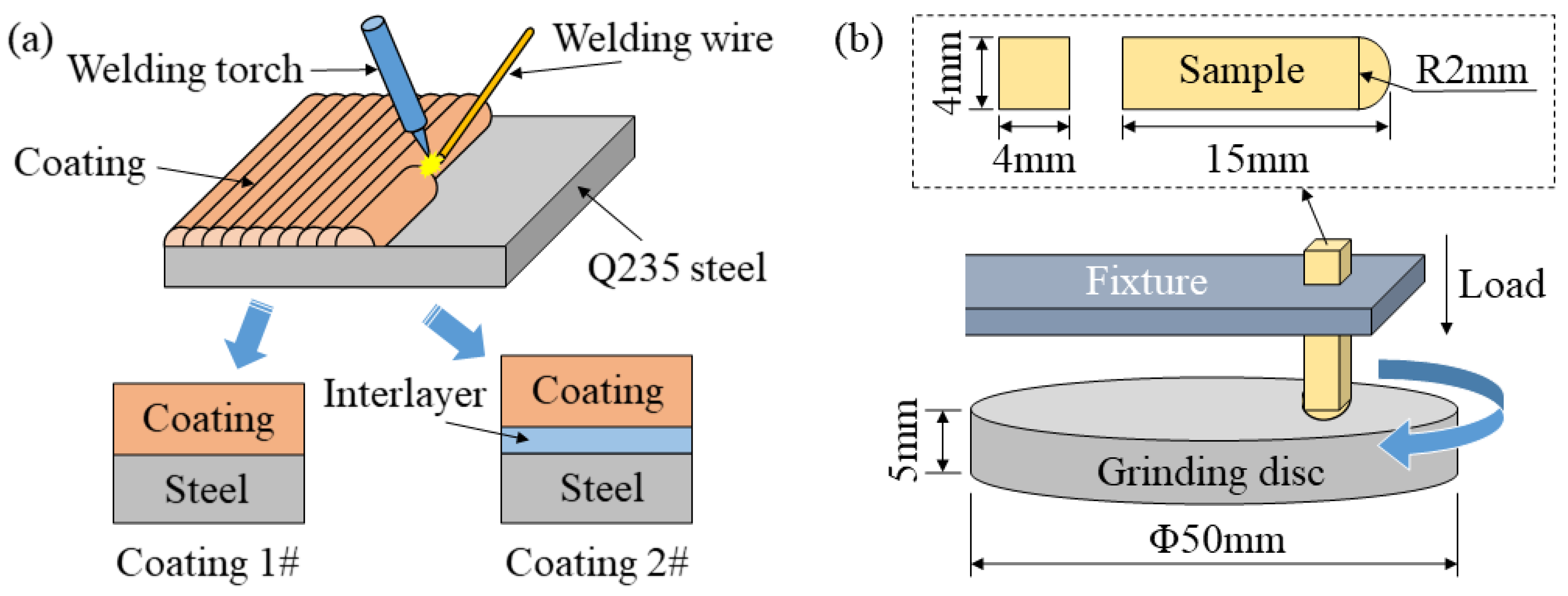
2.1. Coating Preparation
2.2. Microstructure and Property Characterization
3. Results
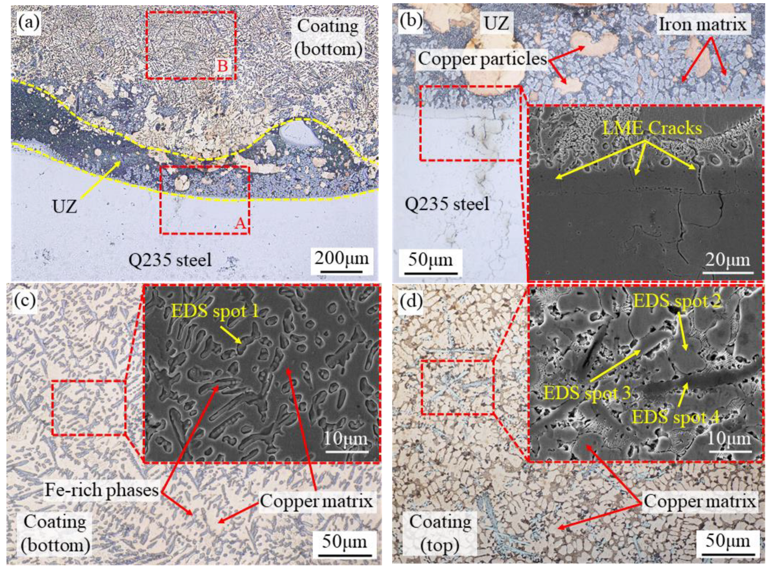
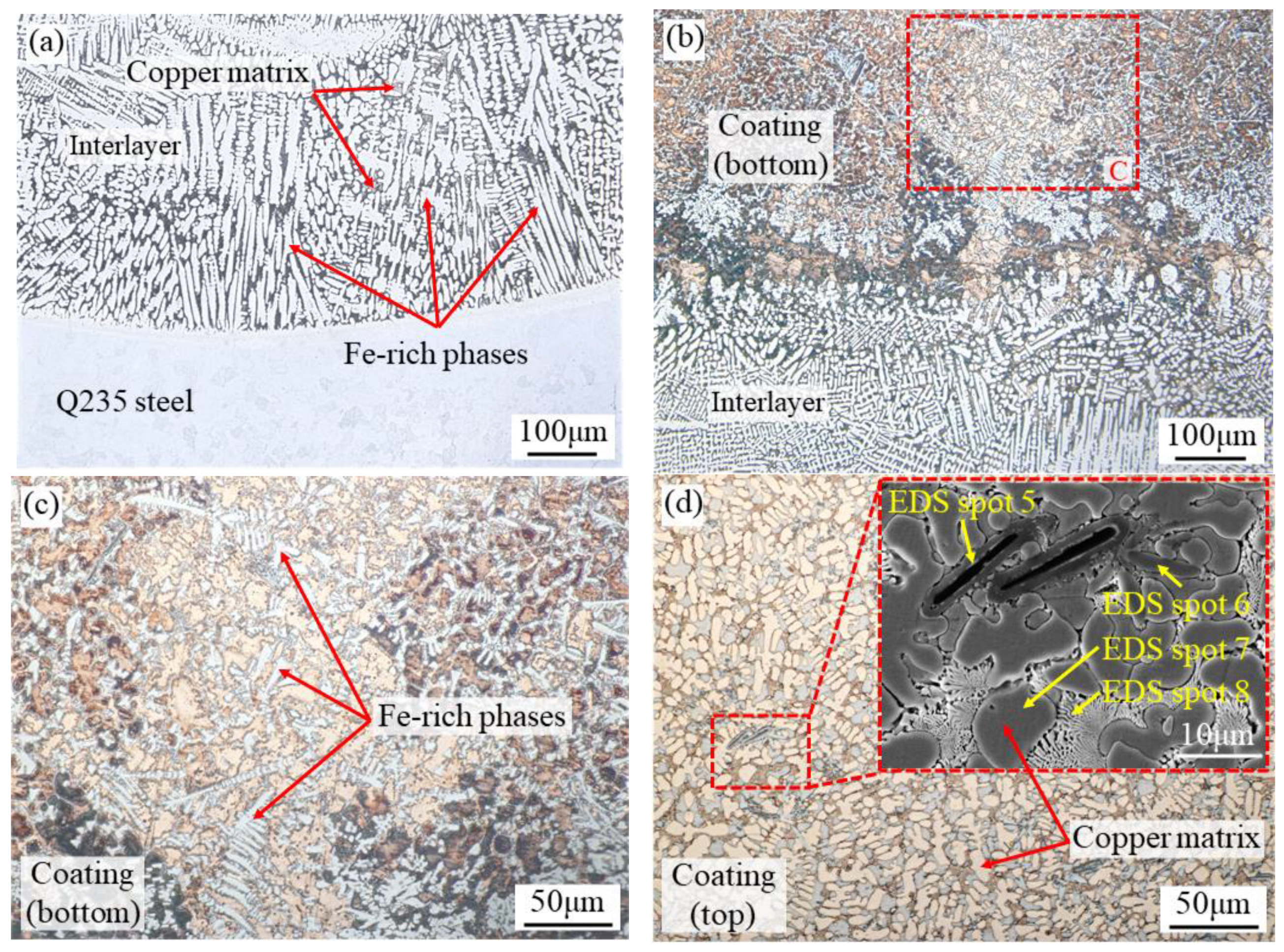
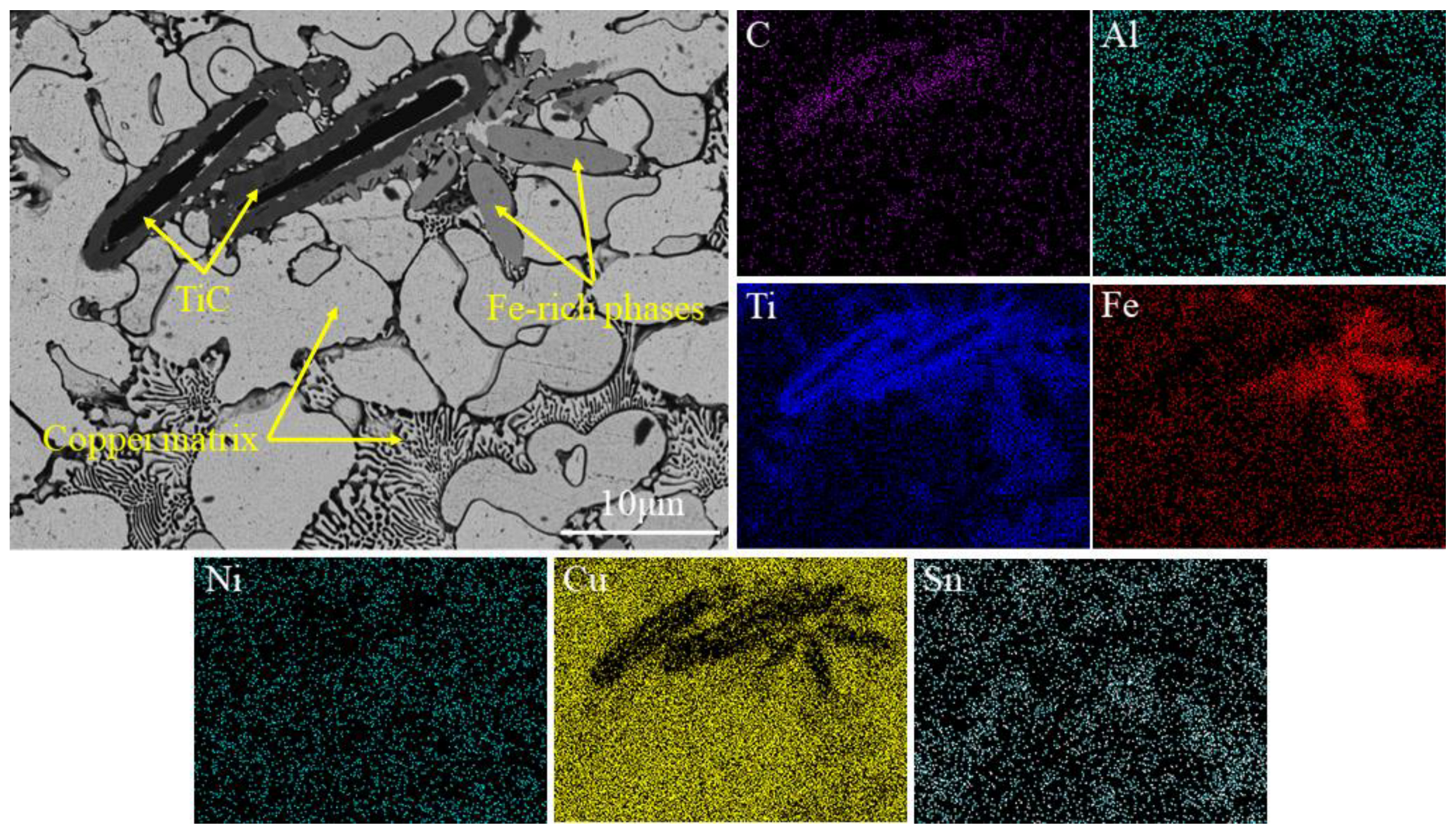
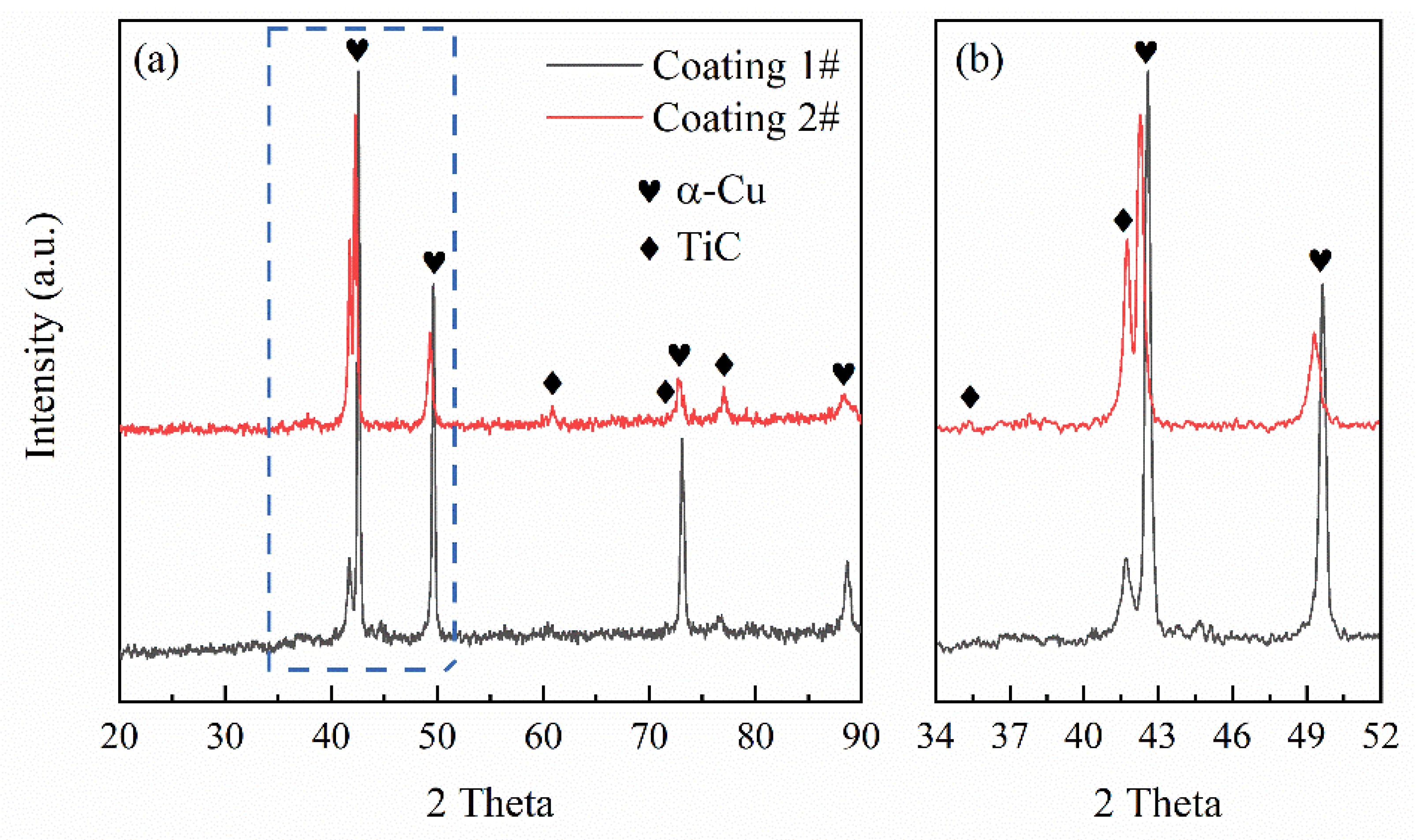
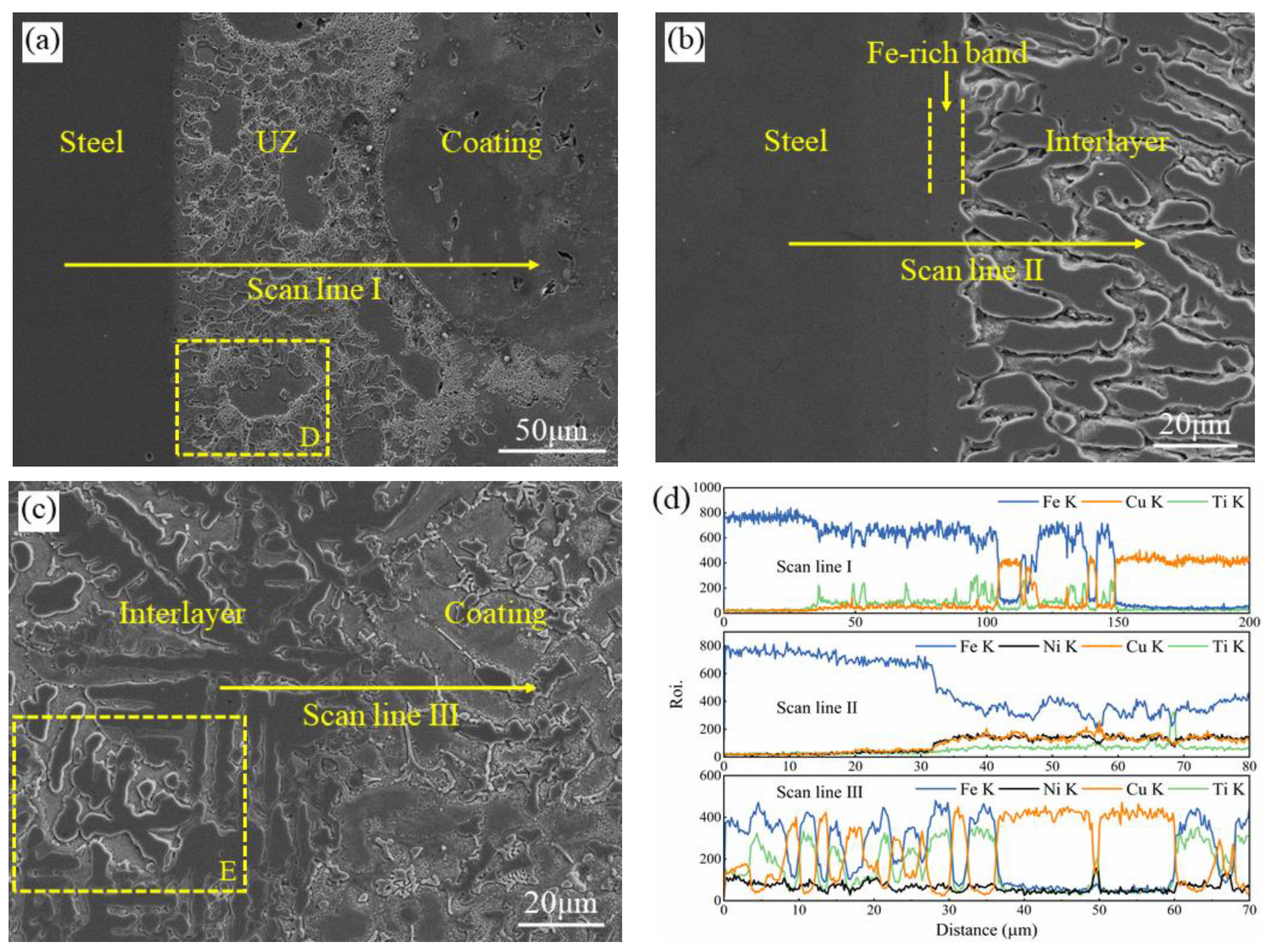
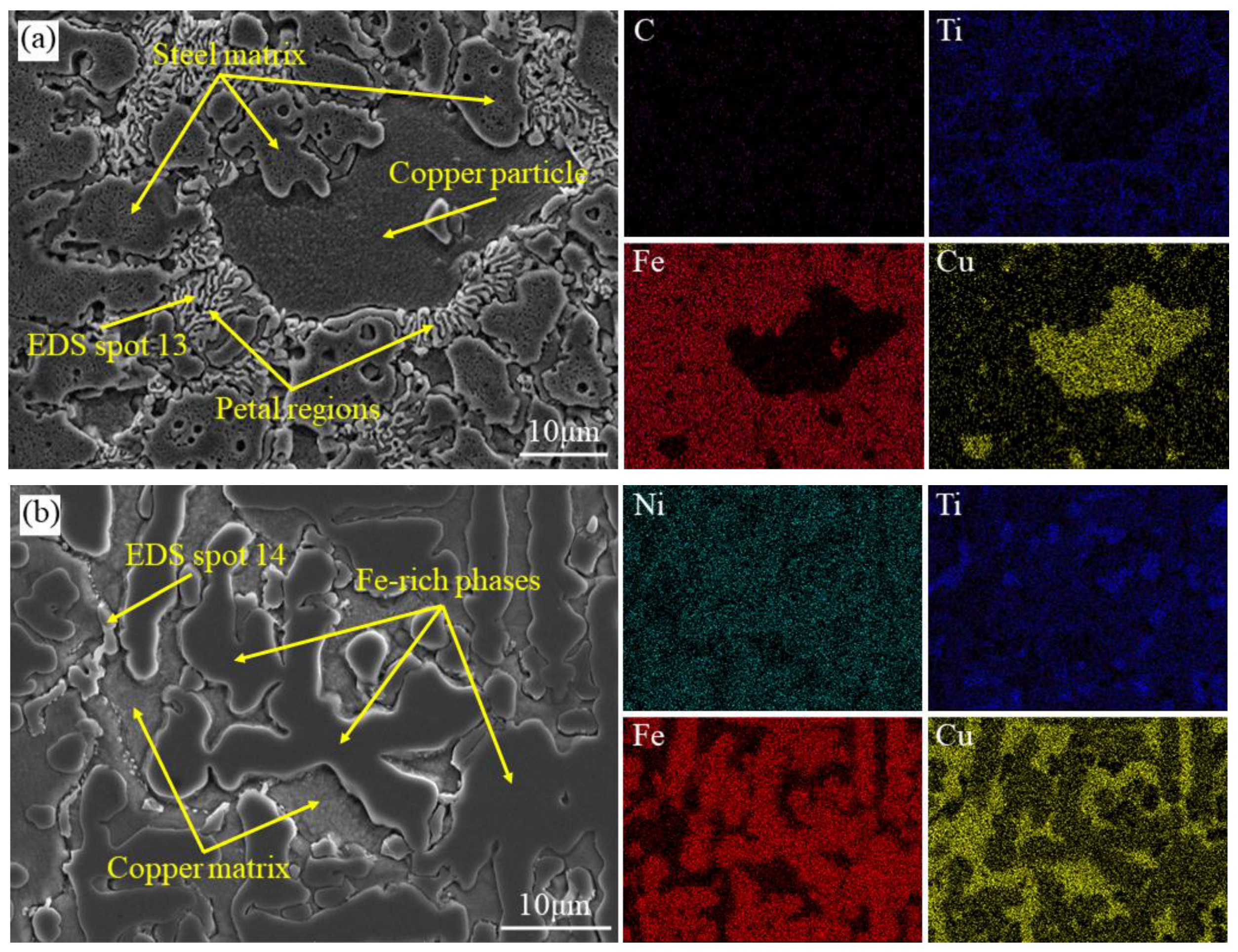
3.1. Microstructure and Phase Constituents

| EDS Spots | C K | Al K | Ti K | Fe K | Ni K | Cu K | Sn K |
|---|---|---|---|---|---|---|---|
| 1 | - | 1.5 | 29.6 | 63.4 | - | 5.1 | 0.3 |
| 2 | - | 3.1 | 4.5 | 1.4 | - | 90.0 | 1.0 |
| 3 | - | 2.1 | 34.6 | 52.7 | - | 10.2 | 0.4 |
| 4 | 10.7 | 0.3 | 85.2 | 0.7 | - | 3.0 | 0.1 |
| 5 | 15.5 | 0.1 | 77.5 | 1.8 | 0.6 | 4.3 | 0.2 |
| 6 | - | 2.9 | 40.5 | 43.7 | 3.3 | 9.2 | 0.3 |
| 7 | - | 6.4 | 3.3 | 1.1 | 0.6 | 88.0 | 0.6 |
| 8 | - | 2.0 | 3.8 | 1.0 | 0.7 | 92.1 | 0.4 |
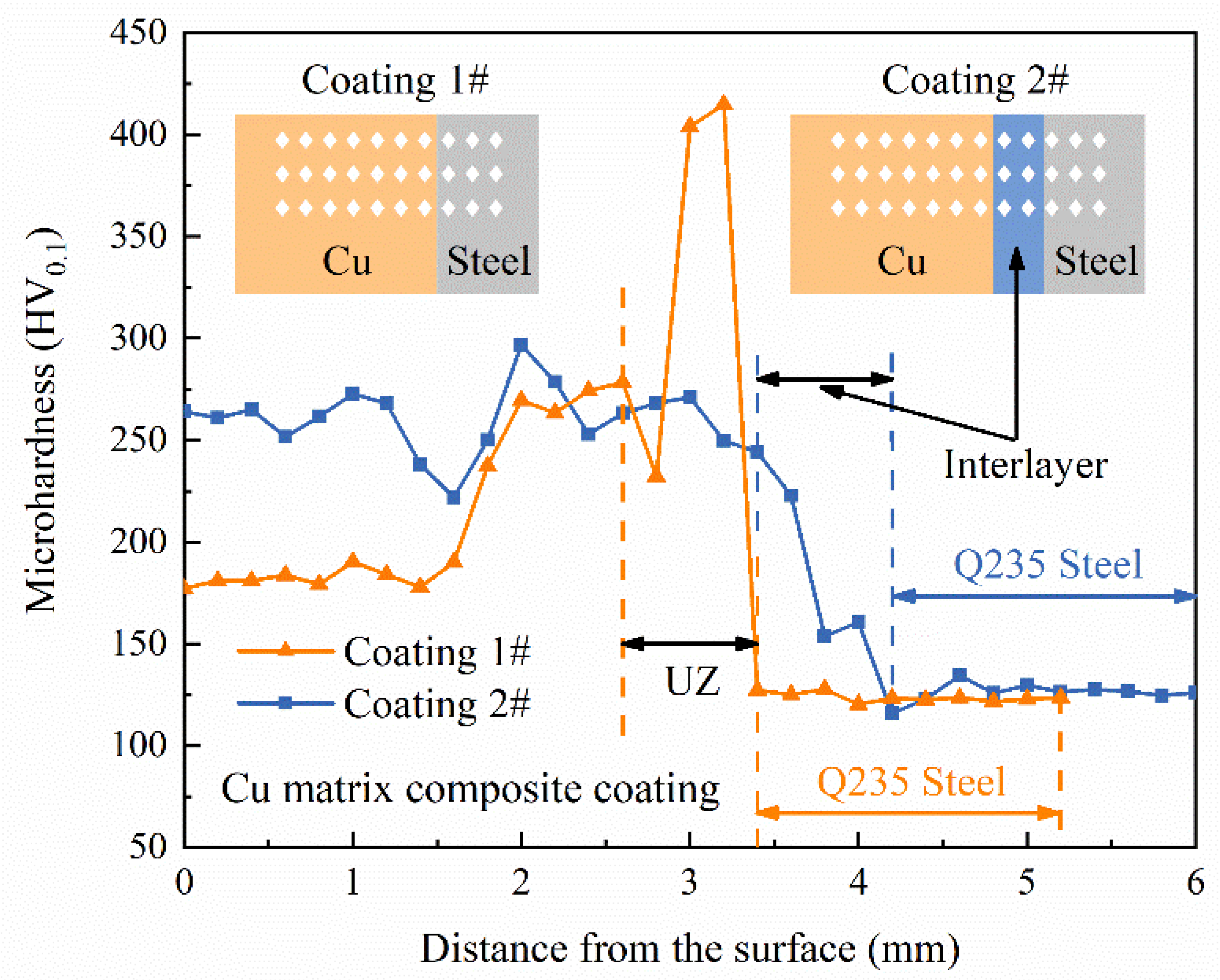
3.2. Microhardness
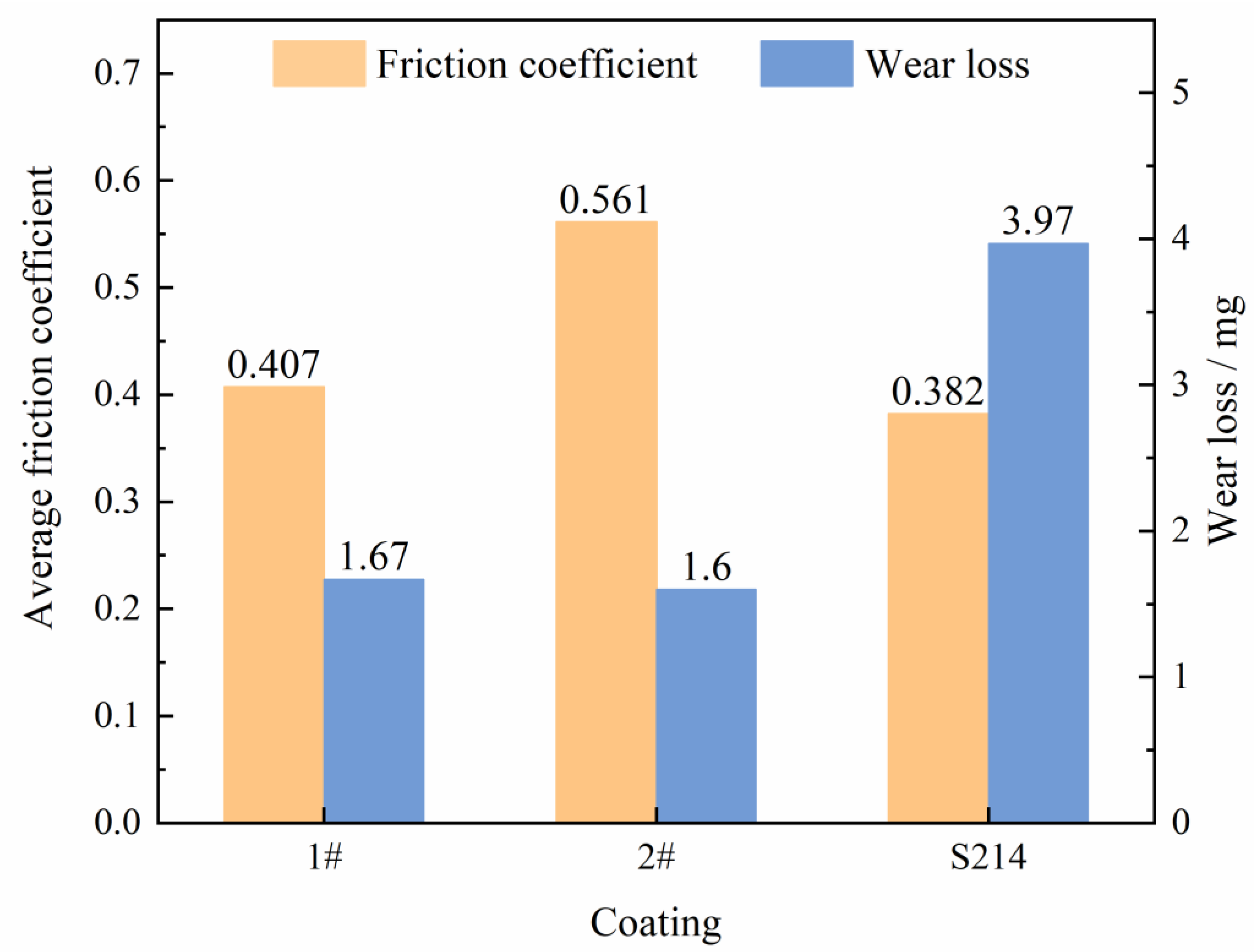
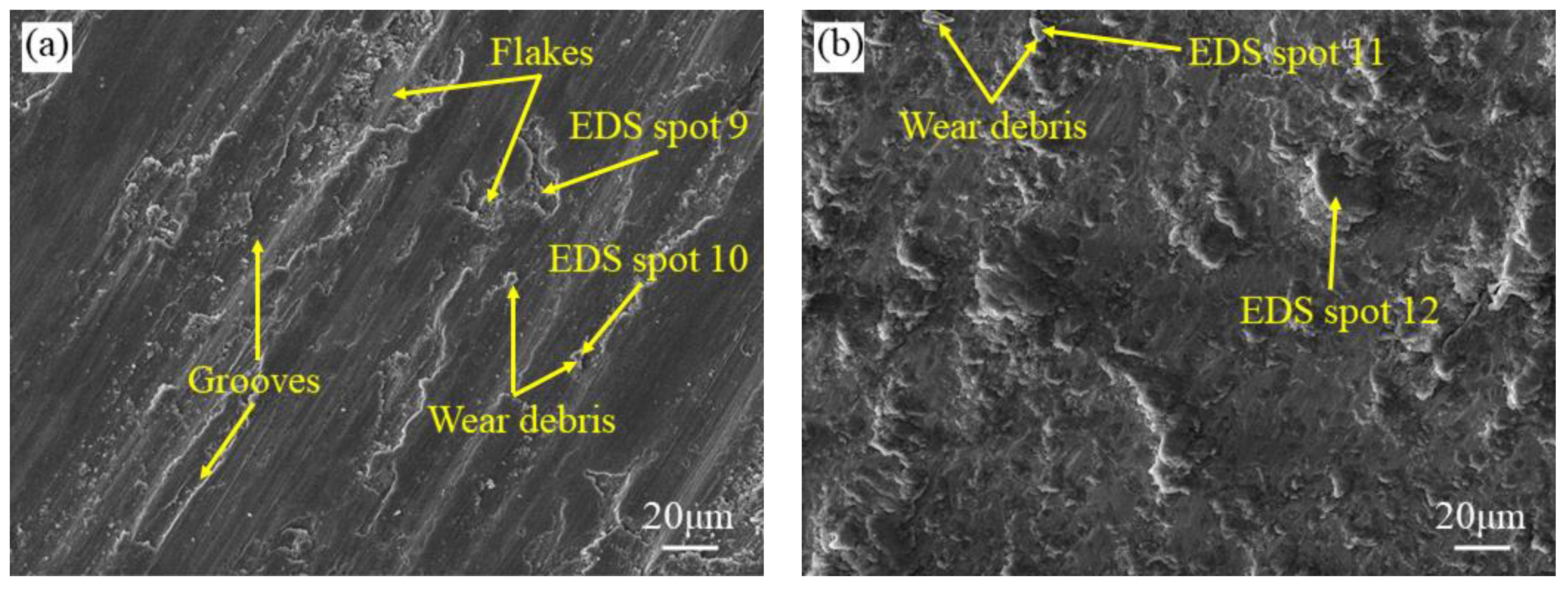
3.3. Wear Behavior
4. Discussion
4.1. Effect of the Interlayer on Elimination of High-Hardness UZ
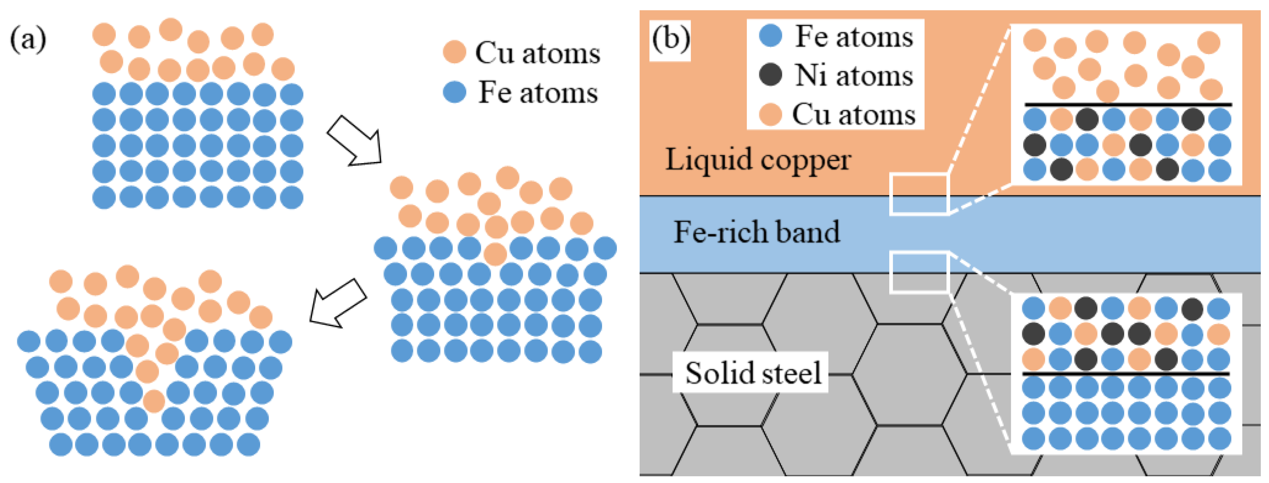
4.2. Effect of the Interlayer on Inhibiting LME Cracks
4.3. Effect of Interlayer on Properties of Composite Coatings
5. Conclusions
Author Contributions
Funding
Institutional Review Board Statement
Informed Consent Statement
Data Availability Statement
Conflicts of Interest
References
- Jie, J.C.; Liu, C.B.; Wang, S.H.; Dong, B.W.; Liu, S.C.; Li, T.J. Characterisation of steel/nickel bronze clad strips prepared by continuous solid/liquid bonding method. Mater. Sci. Technol. 2019, 35, 1840–1847. [Google Scholar] [CrossRef]
- Zhang, M.; Zhang, Y.L.; Li, J.; Zhang, S.F.; Du, M.K.; Wang, G. Microstructure and mechanical properties of the joint fabricated between stainless steel and copper using gas metal arc welding. Trans. Indian Inst. Met. 2021, 74, 969–978. [Google Scholar] [CrossRef]
- Chen, S.H.; Yu, X.H.; Huang, J.H.; Yang, J.; Lin, S.B. Interfacial ferrite band formation to suppress intergranular liquid copper penetration of solid steel. J. Alloys Compd. 2019, 773, 719–729. [Google Scholar] [CrossRef]
- Chang, C.C.; Wu, L.H.; Shueh, C.; Chan, C.K.; Shen, I.C.; Kuan, C.K. Evaluation of microstructure and mechanical properties of dissimilar welding of copper alloy and stainless steel. Int. J. Adv. Manuf. Technol. 2017, 91, 2217–2224. [Google Scholar] [CrossRef]
- Najafi, S.; Khanzadeh, M.R.; Bakhtiari, H.; Seyedraoufi, Z.S.; Shajari, Y. Electrochemical investigation of dissimilar joint of pure Cu to AISI 410 martensitic stainless steel fabricated by explosive welding. Surf. Eng. Appl. Electrochem. 2020, 56, 675–683. [Google Scholar] [CrossRef]
- Sabetghadam, H.; Hanzaki, A.Z.; Araee, A.; Hadian, A. Microstructural evaluation of 410 SS/Cu diffusion-bonded joint. J. Mater. Sci. Technol. 2010, 26, 163–169. [Google Scholar] [CrossRef]
- Bai, Y.C.; Zhang, J.Y.; Zhao, C.L.; Li, C.J.; Wang, H. Dual interfacial characterization and property in multi-material selective laser melting of 316L stainless steel and C52400 copper alloy. Mater. Charact. 2020, 167, 110489. [Google Scholar] [CrossRef]
- Cheng, Z.; Liu, H.; Huang, J.H.; Ye, Z.; Yang, J.; Chen, S.H. MIG-TIG double-sided arc welding of copper-stainless steel using different filler metals. J. Manuf. Process. 2020, 55, 208–219. [Google Scholar] [CrossRef]
- Li, Y.N.; Liu, X.B.; Zhou, Z.K.; Zhang, L.; Peng, Z.L.; Robert, B.H. The microstructure and wear resistance of a copper matrix composite layer on copper via nitrogen-shielded arc cladding. Coatings 2016, 6, 67. [Google Scholar] [CrossRef]
- Besnea, D.; Dontu, O.; Avram, M.; Spânu, A.; Rizescu, C.; Pascu, T. Study on laser welding of stainless steel/copper dissimilar materials. IOP Conf. Ser. Mater. Sci. Eng. 2016, 147, 012047. [Google Scholar] [CrossRef] [Green Version]
- Ramachandran, S.; Lakshminarayanan, A.K. An insight into microstructural heterogeneities formation between weld subregions of laser welded copper to stainless steel joints. Trans. Nonferrous Met. Soc. China 2020, 30, 727–745. [Google Scholar] [CrossRef]
- Xu, H.; Xu, M.J.; Yu, C.; Lu, H.; Wei, X.; Chen, J.M.; Xu, J.J. Effect of the microstructure in unmixed zone on corrosion behavior of 439 tube/308L tube-sheet welding joint. J. Mater. Process. Technol. 2017, 240, 162–167. [Google Scholar] [CrossRef]
- Devendranath, R.K.; Patel, S.D.; Sri, P.S.; Choudhury, D.J.; Prabaharan, P.; Arivazhagan, N.; Xavior, M.A. Influence of filler metals and welding techniques on the structure–property relationships of Inconel 718 and AISI 316L dissimilar weldments. Mater. Des. 2014, 62, 175–188. [Google Scholar] [CrossRef]
- Zhang, Q.Y.; Dong, Q.P.; Wang, X.N.; Wang, Z.J.; Sun, D.K.; Zhu, M.F.; Qian, Y.H.; Hiromi, N. Predictions of solute mixing in a weld pool and macrosegregation formation during dissimilar-filler welding of aluminum alloys: Modeling and experiments. J. Mater. Res. Technol. 2020, 9, 12080–12090. [Google Scholar] [CrossRef]
- Gan, Z.T.; Yu, G.; He, X.L.; Li, S.X. Numerical simulation of thermal behavior and multicomponent mass transfer in direct laser deposition of Co-base alloy on steel. Int. J. Heat Mass Transfer 2017, 104, 28–38. [Google Scholar] [CrossRef]
- Adomako, N.K.; Kim, J.H. Microstructure and mechanical properties of dissimilar laser lap joint between CoCrFeMnNi-high entropy alloy and duplex stainless steel. Mater. Lett. 2021, 288, 129354. [Google Scholar] [CrossRef]
- Cheng, Z.; Huang, J.H.; Ye, Z.; Chen, Y.; Yang, J.; Chen, S.H. Microstructures and mechanical properties of copper-stainless steel butt-welded joints by MIG-TIG double-sided arc welding. J. Mater. Process. Technol. 2019, 265, 87–98. [Google Scholar] [CrossRef]
- Meng, Y.F.; Li, X.W.; Gao, M.; Zeng, X.Y. Microstructures and mechanical properties of laser-arc hybrid welded dissimilar pure copper to stainless steel. Opt. Laser Technol. 2019, 111, 140–145. [Google Scholar] [CrossRef]
- Switzner, N.; Queiroz, H.; Duerst, J.; Yu, Z. Si-bronze to 304 stainless steel GTA weld fusion zone microstructure and mechanical properties. Mater. Sci. Eng. A 2018, 709, 55–64. [Google Scholar] [CrossRef]
- Soysal, T.; Kou, S.; Tat, D.; Pasang, T. Macrosegregation in dissimilar-metal fusion welding. Acta Mater. 2016, 110, 149–160. [Google Scholar] [CrossRef] [Green Version]
- Zhang, M.; Zhang, Y.L.; Du, M.K.; Zhang, S.F.; Lei, L.Y. Experimental characterization and microstructural evaluation of silicon bronze-alloy steel bimetallic structures by additive manufacturing. Metall. Mater. Trans. A 2021, 52, 4664–4674. [Google Scholar] [CrossRef]
- Rahman, A.; Abdel, R.N.A.; El, K.M.R. Effect of heat input on the microstructure and properties of dissimilar weld joint between Incoloy 28 and superaustenitic stainless steel. Acta Metall. Sin. 2014, 27, 259–266. [Google Scholar] [CrossRef]
- Khan, W.N.; Chhibber, R. Effect of filler metal on solidification, microstructure and mechanical properties of dissimilar super duplex/pipeline steel GTA weld. Mater. Sci. Eng. A 2021, 803, 140476. [Google Scholar] [CrossRef]
- Chun, E.J.; Lee, J.H.; Kang, N. Unmixing behaviour in dissimilar laser welds for duplex and austenitic stainless steels. Sci. Technol. Weld. Joining 2019, 24, 263–275. [Google Scholar] [CrossRef]
- Sun, Z.C.; Li, P.Y.; Zhang, T.; Wang, J.B.; Xu, D.; Chen, H.; Liu, D.H.; Pei, Y.Y. Effect of stress and Si on liquid metal embrittlement of 316L (N)-copper. Mater. Sci. Technol. 2021, 37, 552–559. [Google Scholar] [CrossRef]
- Wang, J.; de Castro, C.C.; Lu, X.F. The formation mechanisms and improvement measures for penetrating cracks in QAl9-4/Q345B welded joint. J. Mater. Eng. Perform. 2020, 29, 2346–2354. [Google Scholar] [CrossRef]
- Magnabosco, I.; Ferro, P.; Bonollo, F.; Arnberg, L. An investigation of fusion zone microstructures in electron beam welding of copper–stainless steel. Mater. Sci. Eng. A 2006, 424, 163–173. [Google Scholar] [CrossRef]
- Cao, S.L.; Liang, J.; Wang, L.Q.; Zhou, J.S. Effects of NiCr intermediate layer on microstructure and tribological property of laser cladding Cr3C2 reinforced Ni60A-Ag composite coating on copper alloy. Opt. Laser Technol. 2021, 142, 106963. [Google Scholar] [CrossRef]
- Liu, F.; Liu, C.S.; Chen, S.Y.; Tao, X.Q.; Zhang, Y. Laser cladding Ni–Co duplex coating on copper substrate. Opt. Lasers Eng. 2010, 48, 792–799. [Google Scholar] [CrossRef]
- Shi, Z.P.; Wang, Z.B.; Wang, J.Q.; Qiao, Y.X.; Chen, H.N.; Xiong, T.Y.; Zheng, Y.G. Effect of Ni interlayer on cavitation erosion resistance of NiTi cladding by tungsten inert gas (TIG) surfacing process. Acta Metall. Sin. 2020, 33, 415–424. [Google Scholar] [CrossRef] [Green Version]
- Zhang, X.C.; Sun, C.; Pan, T.; Flood, A.; Zhang, Y.L.; Li, L.; Liou, F. Additive manufacturing of copper–H13 tool steel bi-metallic structures via Ni-based multi-interlayer. Addit. Manuf. 2020, 36, 101474. [Google Scholar] [CrossRef]
- Li, J.H.; Zhang, Y.L.; Du, M.K.; Zhang, M.; Li, J.; Lei, L.Y. Effect of alloy elements on the interface connection mechanism and properties of copper/steel welded joints. Trans. China Weld. Inst. 2021, 42, 34–41+100. [Google Scholar]
- Alfredo, M.; Oscar, P.; Jhon, O. Influence of gas pressure on the mechanical and tribological properties of Cu-Al coatings deposited via thermal spray. Coatings 2019, 9, 722. [Google Scholar]
- Manu, K.; Jezierski, J.; Ganesh, M.R.S.; Shankar, K.V.; Narayanan, S.A. Titanium in cast Cu-Sn alloys—A review. Materials 2021, 14, 4587. [Google Scholar] [CrossRef] [PubMed]
- Zhang, D.D.; He, X.Y.; Liu, Y.; Bai, F.; Wang, J.G. The effect of in situ nano-sized particle content on the properties of TiCx/Cu composites. J. Mater. Res. Technol. 2021, 10, 453–459. [Google Scholar] [CrossRef]
- Gan, W.P.; Jin, Z.P. Miscibility gap in the Fe-Cu-Ni system at 1173 K. J. Mater. Sci. Technol. 1992, 3, 181–184. [Google Scholar]
- Mou, G. Study on Microstructure Control of Interface Layer and Properties of TC4/304L Joints Fabricated by CMT; Shanghai Jiao Tong University: Shanghai, China, 2020. [Google Scholar]
- Van, V.L.H. Intergranular energy of iron and some iron alloys. J. Met. 1951, 3, 251–259. [Google Scholar]
- Yuasa, M.; Mabuchi, M. Effects of segregated Cu on an Fe grain boundary by first-principles tensile tests. J. Phys. Condens. Matter. 2010, 22, 505705. [Google Scholar] [CrossRef] [PubMed]
- Chen, C.; Zhou, J.; Xue, F.; Wu, Q.P. Elimination of liquid metal embrittlement cracks during arc cladding of tin bronze on steel sheet. Mater. Lett. 2020, 269, 127646. [Google Scholar] [CrossRef]
- Yang, L.; Yu, T.B.; Li, M.; Zhao, Y.; Sun, J.Y. Microstructure and wear resistance of in-situ synthesized Ti (C, N) ceramic reinforced Fe-based coating by laser cladding. Ceram. Int. 2018, 44, 22538–22548. [Google Scholar] [CrossRef]


| C | Mn | Si | S | P | Fe |
|---|---|---|---|---|---|
| ≤0.22 | ≤1.40 | ≤0.35 | ≤0.05 | ≤0.045 | Bal. |
| Materials | C | Al | Ti | Sn | Ni | Si | Mn | Cu |
|---|---|---|---|---|---|---|---|---|
| Coating | 0.40 | 1.00 | 8.80 | 4.40 | - | 0.25 | 0.25 | Bal. |
| Interlayer | - | - | 2.90 | / | 10.30 | 0.30 | 0.30 | Bal. |
| S214 | - | 7.00–8.50 | - | - | - | - | - | Bal. |
| EDS Spots | C K | O K | Al K | Ti K | Fe K | Ni K | Cu K | Sn K |
|---|---|---|---|---|---|---|---|---|
| 9 | 0.1 | - | 1.5 | 20.4 | 3.7 | - | 64.3 | 10.0 |
| 10 | - | 41.5 | - | 9.1 | 7.1 | - | 40.6 | 1.7 |
| 11 | - | 55.9 | 1.5 | 6.4 | 8.4 | 0.8 | 26.1 | 1.0 |
| 12 | 0.1 | 53.8 | 1.3 | 6.4 | 8.6 | 0.6 | 27.9 | 1.2 |
| EDS Spots | C K | Al K | Ti K | Fe K | Ni K | Cu K | Sn K |
|---|---|---|---|---|---|---|---|
| 13 | - | 3.3 | 8.5 | 83.1 | - | 4.9 | 0.1 |
| 14 | - | 1.7 | 28.1 | 49.5 | 13.3 | 6.1 | 1.3 |
Publisher’s Note: MDPI stays neutral with regard to jurisdictional claims in published maps and institutional affiliations. |
© 2022 by the authors. Licensee MDPI, Basel, Switzerland. This article is an open access article distributed under the terms and conditions of the Creative Commons Attribution (CC BY) license (https://creativecommons.org/licenses/by/4.0/).
Share and Cite
Li, J.; Lei, L.; Du, M.; Zhang, Z.; Zhang, M. Effects of Cu-Ni-Ti Interlayer on Microstructure and Wear Resistance around Gas Tungsten Arc Cladding Copper Matrix Composite Coatings on Steel. Coatings 2022, 12, 1360. https://doi.org/10.3390/coatings12091360
Li J, Lei L, Du M, Zhang Z, Zhang M. Effects of Cu-Ni-Ti Interlayer on Microstructure and Wear Resistance around Gas Tungsten Arc Cladding Copper Matrix Composite Coatings on Steel. Coatings. 2022; 12(9):1360. https://doi.org/10.3390/coatings12091360
Chicago/Turabian StyleLi, Jihong, Longyu Lei, Mingke Du, Zhiqiang Zhang, and Min Zhang. 2022. "Effects of Cu-Ni-Ti Interlayer on Microstructure and Wear Resistance around Gas Tungsten Arc Cladding Copper Matrix Composite Coatings on Steel" Coatings 12, no. 9: 1360. https://doi.org/10.3390/coatings12091360