1. Introduction
Ti6Al4V alloy is characterized by its light weight, high specific strength, non-magnetic properties, and good biocompatibility [
1,
2]. Currently, it is widely used in the fields of national defense; the biomedical and marine industries; and aerospace, especially in the manufacture of aero–engine hot-end components (such as compressor blades, etc.), where the lightweight Ti6Al4V alloy has shown great potential for engineering applications [
3,
4,
5,
6,
7,
8,
9]. However, the literature has reported that these Ti alloy components experienced prominent oxidation erosion during high-temperature air exposure [
10,
11,
12,
13]. In addition, the literature reported that these components also suffered from severe simultaneous oxidation and degradation reactions during marine environment exposure (e.g., hot salt or hot salt–water vapor) [
14,
15,
16,
17,
18]. The strong synergistic damage of the oxidation and degradation reactions greatly threatens the long-term service life of these hot end components. Therefore, it is necessary to clarify the corrosion degradation behaviors and mechanisms of Ti alloy components during this specific marine environment exposure.
The oxidation and corrosion behaviors of Ti alloy components are the current research focus in the field of corrosion and protection [
19,
20,
21,
22,
23]. For example, Bower. K et al. [
20] reported that the mass of this alloy hardly changed after approximately 400 h salt spray exposure, but a TiO
2 layer grew on the surface of this alloy. Meanwhile, a significant oxygen-rich layer appeared beneath the oxide layer and caused the embrittlement and property degradation of this alloy. Aca et al. [
13] investigated the oxidation behavior of the Ti alloy at 500–600 °C. They found that TiO
2 and Al
2O
3 were the main constituent phases of the oxide layer. Dai et al. [
24] reported that the Cl
2 product formed during the hot salt corrosion test of the Ti2AlNb alloy, which further reacted with the substrate to produce volatile chlorides that resulted in severe cracking of the oxide layer. Wang et al. [
14] investigated the oxidation behavior of Ti6Al4V in water vapor at 600–800 °C. The results show that the surface of the sample appeared to be dominated by alumina and rutile phases, and the hardness increased significantly with the increasing temperature.
Apparently, the damage failure characteristics of the Ti alloys in different marine environments are very different. In addition, the oxidative erosion and degradation reactions show a significant effect on their corrosion resistance during the marine environment exposure. Although these current results provided feasible explanations for the corrosion failure behaviors of Ti alloys in different marine environments, these degradation mechanisms are still expected to be further strengthened in the upcoming investigations. In this study, a detailed comparison of the corrosion degradation behaviors of Ti6Al4V alloys in different environments was described by the oxidation, salt spray, hot salt, and hot salt–water vapor synergy tests; the potential corrosion mechanism will be discussed in detail.
2. Materials and Methods
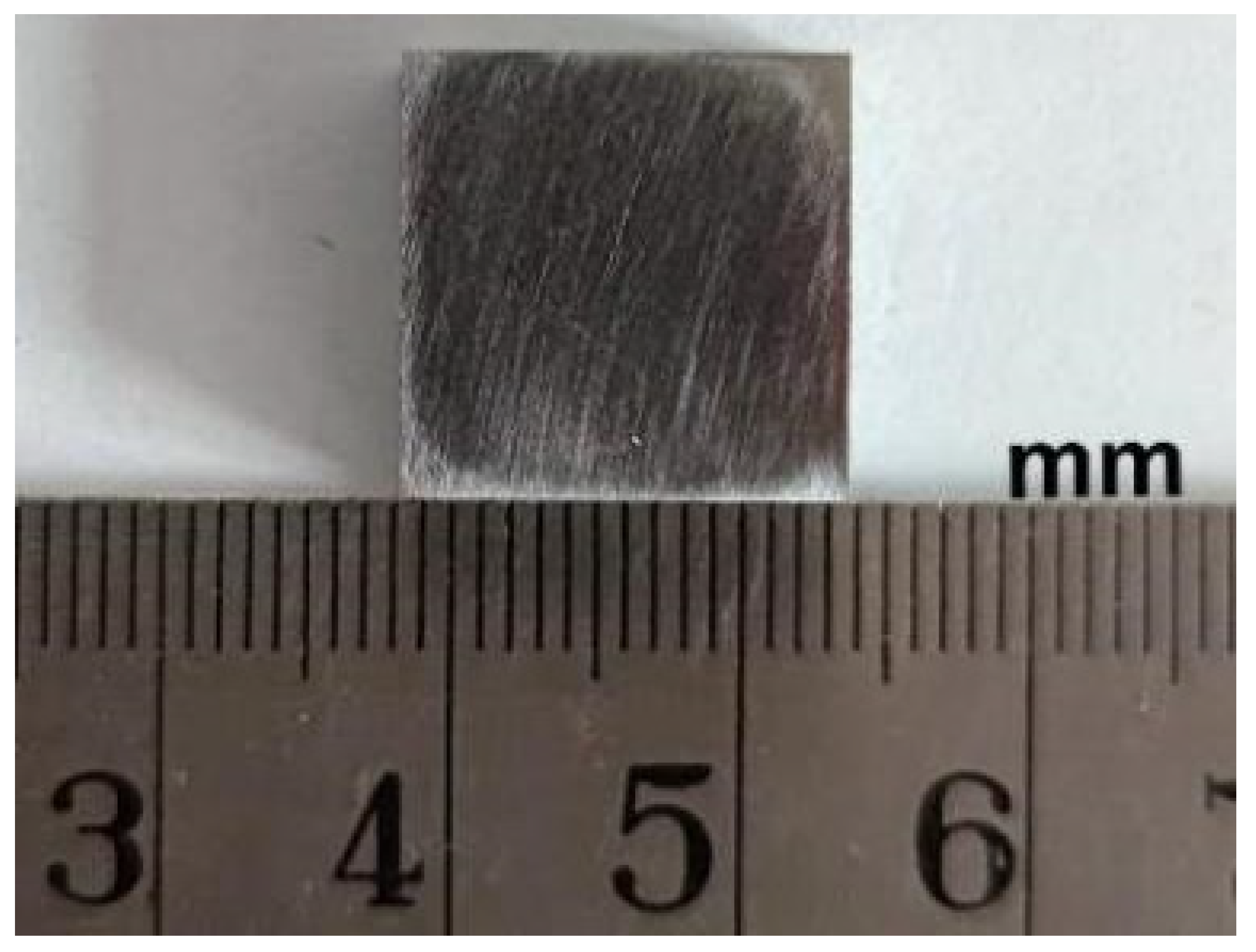
The test material is Ti6Al4V alloy, which is a typical (α + β) type alloy. The length, width, and thickness of this sample were 15 mm, 15 mm, and 5 mm (see
Figure 1), respectively. The individual elemental contents of the original samples are shown in
Table 1.
These samples were sanded by using 320 grit and 600 grit SiC sandpapers and then cleaned by ultrasonic in ethanol solution for 20 min. The specific experimental design is shown in
Table 2.
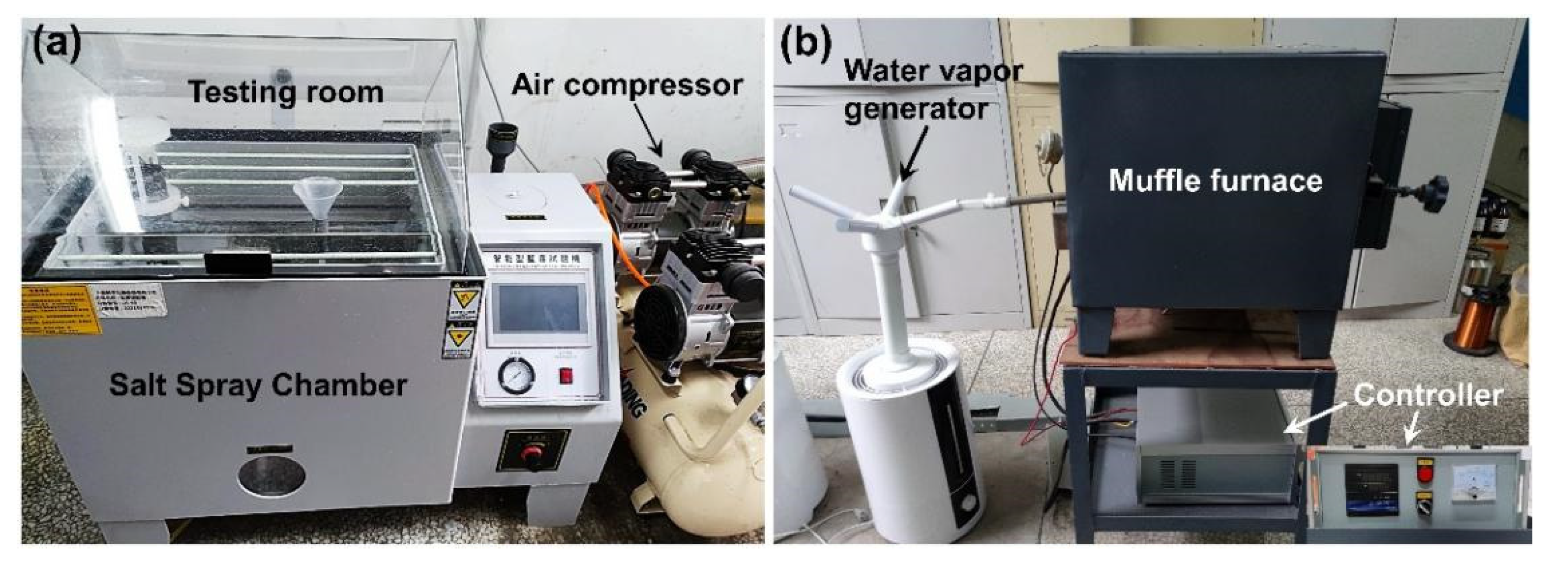
As shown in
Figure 2a, the salt spray test was conducted in a salt spray tester (JK-60, Shanghai Meiyu Instruments Co., ShangHai, China). The test was set to a cycle of 24 h for 50 cycles. The solution in the salt spray chamber was a mixed salt solution with a concentration of 5% ± 0.1% configured from 25 wt.% NaCl + 75 wt.% Na
2SO
4. The pH value of this solution was adjusted to 4 with sulfuric acid. The ambient temperature in the test chamber was set to 35 ± 2 °C, and the spray preheating temperature was 46 °C. The atomization conditions were based on 0.28 m
3 space to atomize 2.8 L of solution in 24 h, and the settling rate was adjusted to 1–3 mL/(80 cm
2·h). The pH value of this salt solution was measured once every 24 h.
High-temperature oxidation and high-temperature hot salt tests were performed in a muffle furnace. The hot salt–water vapor synergy test was completed in a muffle furnace equipped with a water vapor generator (see
Figure 2b). Firstly, a salt mixture of 75 wt.% Na
2SO
4 + 25 wt.% NaCl was coated on the samples that were used for hot salt corrosion and hot salt–water vapor tests. To ensure the uniformity of the salt film on the coating’s surface, these salt application processes were performed several times to ensure that the salt content of the sample was 3–5 mg/cm
2. The test temperatures and heating rates of these above tests were 650 °C and 10 °C/min, respectively. The test duration time was 400 h. These samples were taken and weighed every 20 h, and the mass changes of these tested samples were weighed by an electronic balance with an accuracy of 0.0001 g. In order to reduce the experimental variation error, all samples were measured with three sets of parallel specimens, and the average mass was taken as the final result.
The crystal structures of all corroded samples were characterized by the X-ray diffraction (XRD, X’ Pert Powder, PANalytical B.V., Almelo, Netherlands) with a Cu-Kα radiation source, a scanning range of 20°–90°, and a scanning time of 2 min. X-ray photoelectron spectrometer (XPS, ESCALAB 250Xi, ThermoFisher, K-Alpha+, Waltham, MA, USA) with an Al-Kα emission source was used to analyze the elemental chemical valence state of the sample surface. The C 1s peak of 284.8 eV was used as the charge calibration peak for the calibration of the spectrum. The surface and cross-sectional images of all corroded samples were characterized by scanning electron microscopy (SEM, Zeiss ∑ IGMA HD, Carl Zeiss, Jena, Germany). The local elemental compositions and distributions of all corroded samples were determined by energy dispersive spectroscopy (EDS).
3. Results
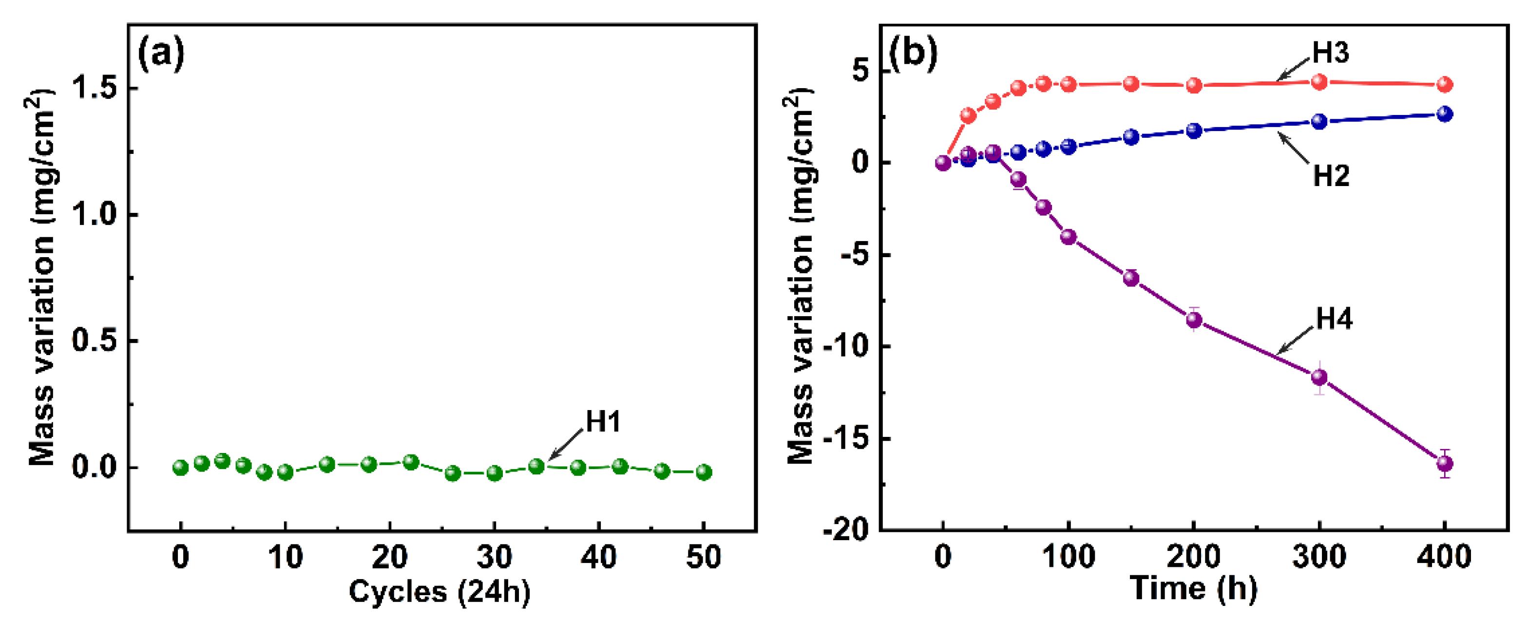
Figure 3 displays the corrosion kinetic curves of all tested samples. As shown in
Figure 3a, sample H1 exhibits a relatively stable weight variation trend during the whole salt spray environment exposure, and a tiny weight loss of 0.018 mg/cm
2 is identified after the 50 day test, indicating good corrosion resistance. As shown in
Figure 3b, sample H2 exhibits an approximately linear weight gain trend, and a weight gain value of 2.657 mg/cm
2 is characterized after a 400 h oxidation test. In comparison, sample H3 showed a parabolic weight gain trend during the hot salt test but also possesses a higher gain value of 4.265 mg/cm
2 at 400 h, indicating a more severe oxidation erosion reaction. However, sample H4 experiences a slight weight gain during the initial stage but suffers from a severe weight loss with the increase of the test time. A high weight loss value of 16.358 mg/cm
2 clearly confirms that a significant corrosion degradation occurs in the hot salt–water vapor synergy environment.
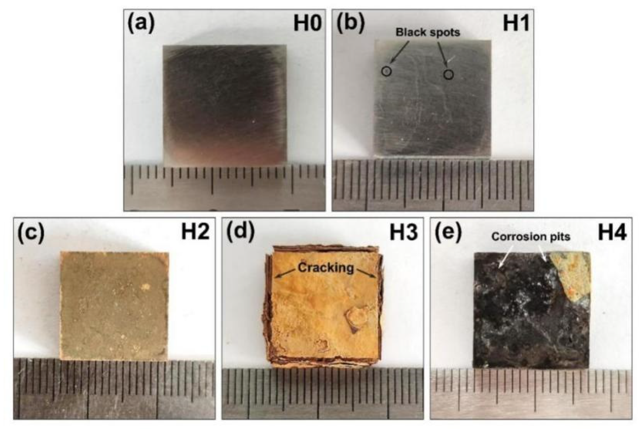
Figure 4 shows the macroscopic morphologies of all tested samples. The untested sample in
Figure 4a has a bright metallic luster accompanied by numerous grooves induced by surface treatment. As shown in
Figure 4b, these grooves are also observed on the surface of sample H1, but the metallic luster disappears and some visible black spots appear on the surface of this sample, indicating that a slight pit corrosion occurs during the salt spray environment exposure. Sample H2 presents a densely earthy yellow surface after the oxidation test; as shown in
Figure 4c, this morphology is accordance with typical titanium oxide [
13]. In contrast, sample H3 has a bright yellow surface accompanied by a thicker oxide layer; as shown in
Figure 4d, the visible oxide layer cracking occurs at the edge of this sample, indicating an accelerated oxidation reaction during the hot salt exposure. As shown in
Figure 4e, this yellow oxide layer almost completely degrades, while a black surface with numerous uneven corrosion pits is observed on the surface of sample H4, proving that a significant degradation reaction occurs during the hot salt–water vapor synergy exposure.
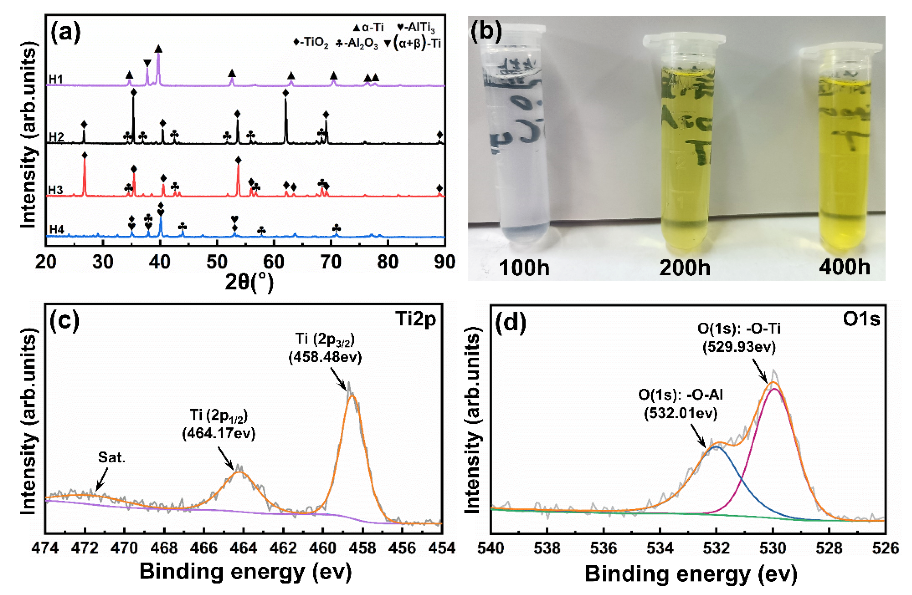
Figure 5a shows the XRD (X-ray diffraction) patterns of all tested samples. These diffraction peaks of sample H1 are mainly attributed to the initial α-Ti and (α + β)-Ti phases. It has been reported that a passivation film consisting mainly of TiO
2 forms on the surface of the titanium alloy during the salt spray exposure [
20,
25]. As shown in
Figure 5c, the Ti2p
3/2 and Ti2p
1/2 peaks in sample H1 locate at 458.48 and 464.17 eV, respectively, which correspond to the Ti–O binding state, confirming the formation of a thin TiO
2 passivation film [
26]. Sample H2 is mainly composed of the TiO
2 and Al
2O
3 phases, indicating a prominent oxidation reaction during the high-temperature air exposure. Sample H3 shows a phase composition similar to that of sample H2, and these visible TiO
2 and Al
2O
3 phases are identified in its XRD pattern. According to the two peaks deconvoluted from the O1s spectrum in
Figure 5d, it can be determined that the oxides on the surface of sample H3 are TiO
2 and Al
2O
3 [
27]. Sample H4 is mainly composed of the TiO
2, Al
2O
3, and AlTi
3 phases, but the intensity of these TiO
2 and Al
2O
3 peaks obviously weakens. In combination with
Figure 5b, a significant color change can be seen in the deionized water for cleaning sample H4, and the color of deionized water is obviously darker with the increase of test time, indicating an aggravated degradation reaction occurs during the hot salt–water vapor synergy exposure.
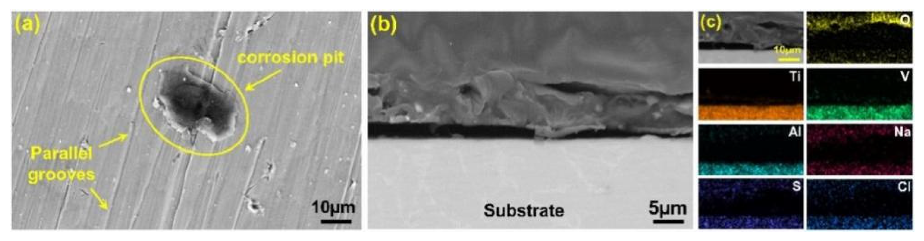
Figure 6 displays the surface and cross-sectional SEM images and EDS spectra of sample H1. As presented in
Figure 6a, sample H1 shows initial surface morphology accompanied by numerous parallel grooves. However, some visible pits also appear on its surface, indicating slight corrosion degradation during the salt spray exposure.
Figure 6b,c show the cross-sectional SEM images and elemental mappings of sample H1 after the salt spray test. It can be found that sample H1 retains its structure, without visible damage or degradation products, indicating a considerable resistance to salt spray corrosion.
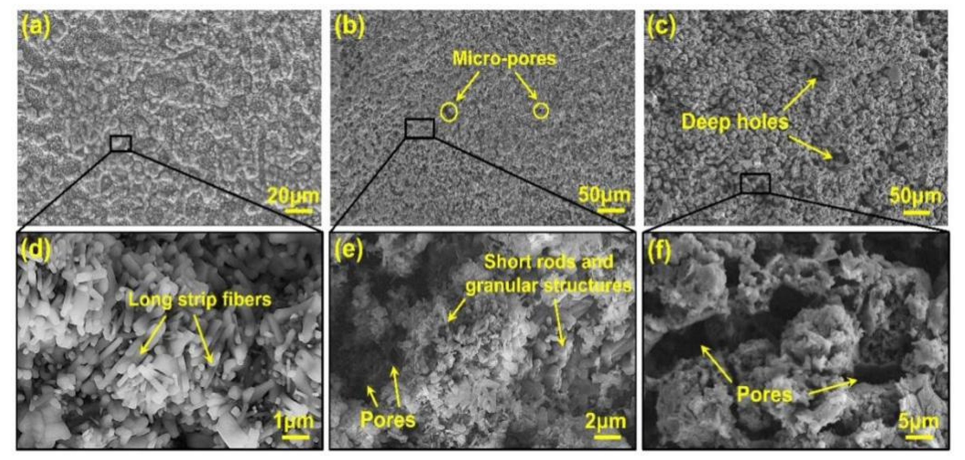
Figure 7a shows the SEM surface images of sample H2 after the oxidation test. A relatively dense and coarse surface feature is characterized in sample H2. The local enlarged image in
Figure 7d shows that numerous long strip fibers distribute on the surface of this sample; as determined by the XRD result of
Figure 5, these fibrous products are accordance with the growth morphology of typical TiO
2 phases [
13]. In contrast, sample H3 shows a loose surface morphology after the hot salt test; as shown in
Figure 7b, plenty of micro-pores appear on the surface of this sample, indicating the occurrence of a potential corrosion degradation reaction. The local enlarged image in
Figure 7e shows that these degradation products are predominantly stacked in short rods and granular structures, and a number of visible pores are clearly observed in the sample. In contrast to sample H3, sample H4 suffers from more serious corrosion damage during the hot salt–water vapor test; as shown in
Figure 7c, a loosely granular surface accompanied by numerous deep holes is clearly observed in this sample. The local enlarged image in
Figure 7f further reveals that the surface of sample H4 is characterize by a loosely honeycomb-like structure, without strip fiber, indicating that a significant degradation reaction occurs during hot salt–water vapor exposure.
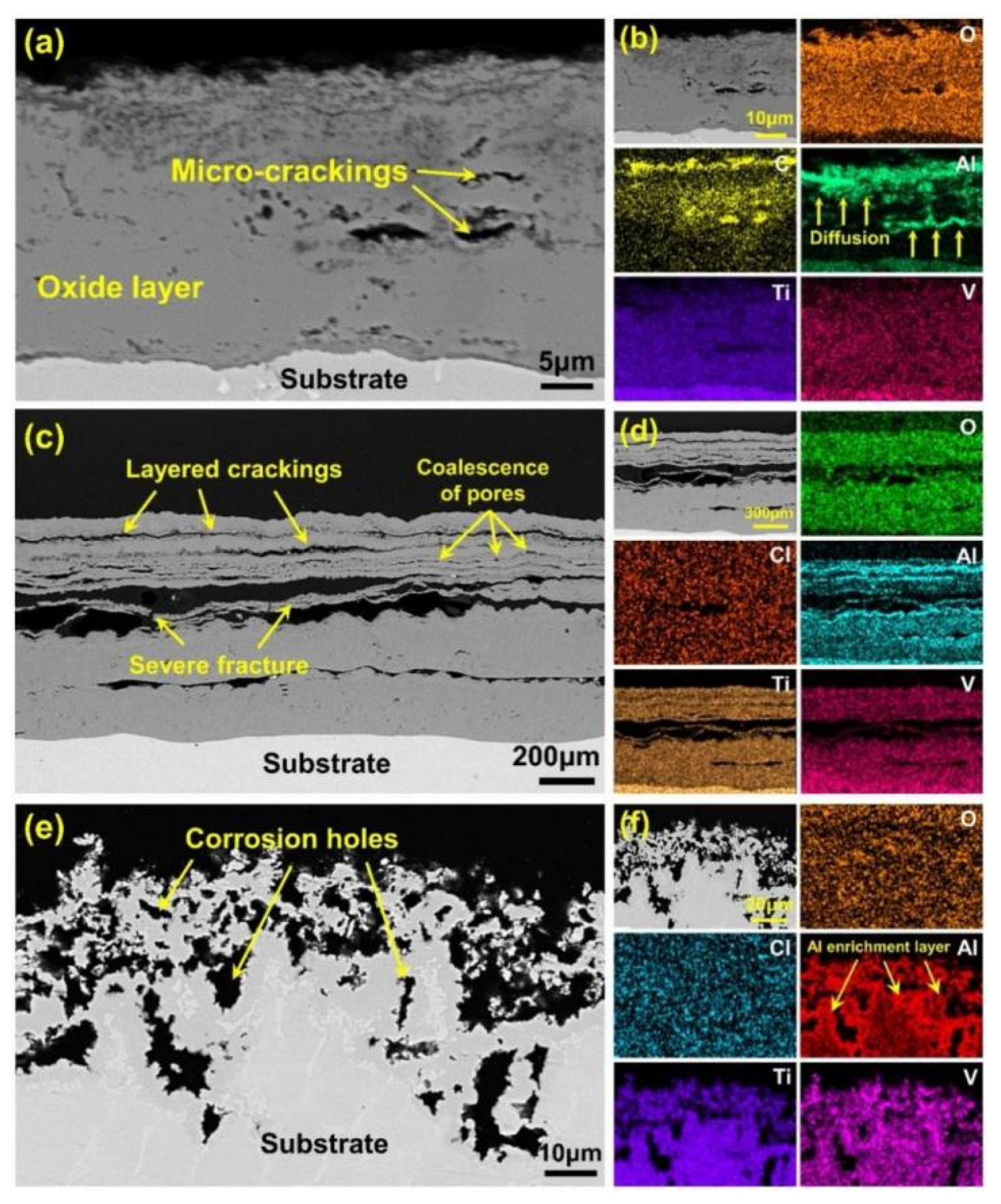
Figure 8 shows the cross-sectional SEM images and element mappings of samples H2, H3, and H4. As shown in
Figure 8a,b, a relatively uniform oxide layer with a thickness of 30 μm forms on the surface of sample H2 during the oxidation test, and some slight crackings also distribute the corresponding enrichment zones of alumina. In contrast, sample H3 experiences an accelerated oxidation reaction during the hot salt test; as shown in
Figure 8c, the thickness value of the oxidation layer in sample H3 is up to 830 μm, which is much higher than in sample H2. Moreover, the oxidation layer of sample H3 suffers from a severe fracture accompanied by some visible layered crackings. The element mappings in
Figure 8d reveal that some enrichment layers of alumina appear in the fracture zones of this oxide layer, indicating a strong correlation between Al enrichment and layered fractures. As shown in
Figure 8e,f, this oxide layer hardly appears on the surface of sample H4, but a large number of corrosion holes form in the substrate matrix, both of which indicate that a severe corrosion degradation reaction occurs during the hot salt–water vapor test.
4. Discussion
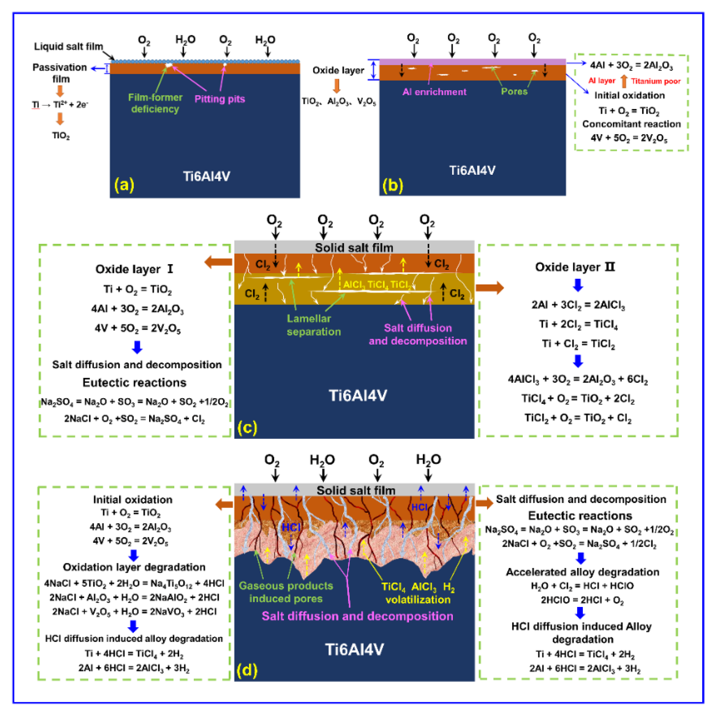
Apparently, Ti6Al4V alloys are very sensitive to these service environments. Reasonable explanations for the damage mechanisms of Ti6Al4V alloys in evaluated environments are illustrated in
Figure 9. As determined by the XRD, XPS, and SEM results, sample H1 shows considerable corrosion resistance during the salt spray environment exposure, which is likely attributed to the formation of a passivation film [
7,
28]. As displayed in
Figure 9a, it has been reported that the standard potential of the 4s electron layer of the Ti6Al4V alloy is very small, and it is relatively easy to lose electrons. Therefore, a passivation film consisting of TiO
2 rapidly forms on the substrate according to the reaction Equation (1).
Although the passivation film is only a few nanometers or tens of nanometers thick, it has a very dense structure with good anti-corrosion properties in salt spray conditions. Unfortunately, the growth of this passivation film tends to be unsustainable as these forming agents (e.g., OH
− and O
2) are not sufficient, which eventually leads to slight local pitting [
29,
30].
Sample H2 exhibits consistent weight gain during the oxidation test, which may have been caused by the prominent oxidation reaction. As shown in
Figure 9b, a severe oxidation reaction occurred in the initial stages. It has been reported that the binding capacity of Ti to O
2 is greater than that of Al and V [
31], and thus the Ti atom firstly reacts with O
2 to form TiO
2 according to Equation (2).
The continuous reaction leads to the decrease of Ti in the surface layer of the substrate and the depletion of Ti at the interface between the oxide layer and substrate. The change of element partial pressure leads to the rapid diffusion of Al in TiO
2 and enrichment outside the oxide layer [
32], forming an Al-rich region and an Al
2O
3 layer according to Equation (3). Meanwhile, the V further reacts with the O
2 to form V
2O
5 according to Equation (4). However, the content of V is so small, and no significant diffraction peaks of V
2O
5 are detected in the XRD.
The O
2 continues to react with the substrate through the oxide layer, resulting in the growth of a thick oxide layer [
33,
34]. However, the diffusion capacity of the O
2 penetrating into the interior of the substrate gradually decreases with the increase of the oxide layer thickness, which is responsible for the gradual decrease in slope of the kinetic curve of the sample H2 (see
Figure 1b).
Compared with sample H2, sample H3 suffers from an aggravated erosion and delamination failure during the hot salt corrosion test, which mainly originated from the accelerated oxidation reaction process. As shown in
Figure 9c, an original oxide layer consisting of the TiO
2, Al
2O
3, and V
2O
5 forms on the substrate surface according to Equations (2)–(4). Some studies have reported that the salt mixture hardly reacts with these oxidation products at 650 °C but possesses a melting point of 645 °C. Therefore, this molten salt mixture diffuses internally through the oxide layer and further undergoes eutectic reactions obeying Equations (5) and (6) [
4,
21].
Subsequently, the Cl
2 further reacts with Ti and Al to form volatile chlorides (e.g., AlCl
3, TiCl
4, and TiCl
2) according to Equations (7)–(9), triggering a rapid degradation of the substrate matrix and the production of a large number of micro-pores [
35].
Moreover, these volatile products further react with the O
2 to produce TiO
2, Al
2O
3, V
2O
5, and Cl
2, according to Equations (10)–(12). As identified by SEM image of
Figure 6b, these reactions between the gaseous products ultimately result in a loose and porous surface morphology.
Obviously, the Cl
2 acts as a key carrier, accelerating the degradation reaction of the substrate, and results in the rapid growth of the oxide layer. As identified by the SEM image of
Figure 8c, the continuous volatilization of chloride and the significant structure differences of these oxides trigger high thermomechanical growth stress, which eventually results in a severe layered separation and local cracking [
36] since the coefficients of thermal expansion of TiO
2, Al
2O
3, and Ti6Al4V alloy are 8.2 × 10
−6, 8.1 × 10
−6, and 10~12 × 10
−6 K
−1, respectively [
25]. Therefore, the significant difference in thermal expansion coefficients between the oxide layer and substrate eventually induces the initiation of surface ring breaking [
37]. Moreover, the visible fracture of this oxide layer further accelerates the penetration of the O
2 and results in the rapid growth of a new oxide layer.
Sample H4 experiences aggravated weight loss during the hot salt–water vapor synergy exposure, which mainly originates from a prominent degradation reaction. In the initial stages of this test, the oxidation of the Ti6Al4V alloy dominates the reaction. As presented in
Figure 9d, an initial composite oxide layer consisting of TiO
2, Al
2O
3, and V
2O
5 rapidly forms on the substrate surface obeying Equations (2)–(4) [
38,
39]. The Cl
2 produced by the eutectic reaction between the mixed salts diffuses in both directions near the oxide layer, and some of the Cl
2 enters the interior of the oxide layer to react with Ti and Al to produce volatile gaseous chloride, which induces the appearance and growth of pores obeying Equations (7)–(9). Meanwhile, the synergistic effect of high-temperature water vapor triggers severe erosive degradation of the surface oxide layer. The degradation reactions of these oxides occur according to Equations (13)–(15), leading to the severe consumption of these oxides and the formation of HCl products [
36,
39].
Subsequently, according to Equations (16) and (17), the hydrochloric acid penetrates the loose oxide layer and further reacts with the matrix metal to form volatile chlorides and H
2.
Additionally, the oxide layer is severely damaged and eroded by the synergistic action of Cl
2 and high-temperature hot salt–water vapor, which results in the downward diffusion of salt mixture. The mixed salt in the molten state further diffuses into the matrix metal, triggering the formation of Cl
2 due to the eutectic reaction. The Cl
2 reacts with H
2O to produce HCl according to Equations (18) and (19). Moreover, the HCl reacts with the matrix metal to form volatile chlorides [
40].
In summary, the water vapor triggers a significant corrosion reaction during the hot salt–water vapor synergy test, which accelerates the degradation process of both these oxides and matrix metals, resulting in the appearance of numerous corrosion pores. Meanwhile, the formation of volatile chlorides and gas products further leads to a severe weight loss of sample H4.


