Article

Investigation of the Nature of the Interaction of Me-MeN-(Me,Mo,Al)N Coatings (Where Me = Zr, Ti, or Cr) with a Contact Medium Based on the Ni-Cr System

1
Spark Plasma Sintering Research Laboratory, Moscow State University of Technology, STANKIN, 127055 Moscow, Russia
2
Scientific Department, A.I. Evdokimov Moscow State University of Medicine and Dentistry, 127473 Moscow, Russia
3
National University of Science & Technology (MISIS), 119049 Moscow, Russia
4
Dianov Fiber Optics Research Center, Prokhorov General Physics Institute of the Russian Academy of Sciences, 119333 Moscow, Russia
*
Author to whom correspondence should be addressed.
Coatings 2022, 12(6), 819; https://doi.org/10.3390/coatings12060819
Submission received: 28 April 2022 / Revised: 29 May 2022 / Accepted: 8 June 2022 / Published: 10 June 2022
(This article belongs to the Special Issue Technologies of Coatings and Surface Hardening for Tool Industry II)

Abstract

:
This paper discusses the results of a study focused on the nature of the interaction of Me-MeN-(Me,Mo,Al)N coatings (where Me = zirconium (Zr), titanium (Ti), or chromium (Cr)) with a contact medium based on the Ni-Cr system. The studies were carried out during the turning of nickel–chromium alloy at different cutting speeds. The hardness of the coatings was found, and their nanostructure and phase composition were studied. The experiments were conducted using transmission electron microscopy (TEM), X-ray diffraction (XRD), and selected area electron diffraction (SAED). According to the studies, at elevated cutting speeds, the highest wear resistance is demonstrated by the tools with the ZrN-based coating, while at lower cutting speeds, the tools with the TiN- and CrN-based coatings had higher wear resistance. At elevated cutting speeds, the experiments detected the active formation of oxides in the ZrN-based coating and less active formation of oxides in the CrN-based coating. No formation of oxides was detected in the TiN-based coating. The patterns of cracking in the coatings were also studied.

1. Introduction

Surface-modifying systems in general, and modifying coatings in particular, are increasingly used in various spheres [1,2,3]. Along with such traditional spheres of application of coatings as the manufacturing of metal-cutting and stamping tools, new areas of surface modification are emerging, including in medicine (in particular, coatings for implants operating in the human body environment) and in the manufacturing of friction pairs, including those functioning in aggressive media and at elevated temperatures [4,5,6,7]. There is an interaction between a coating, on the one hand, and a contact medium (material being machined, human body, or counterbody in a friction pair), on the other hand. In general, the mentioned interaction is a complex and integral phenomenon, which includes, in particular, such factors as adhesion, impact action, interdiffusion, and chemical interaction [8,9,10,11,12]. Since, as a rule, the contact processes take place in an oxygen-containing medium, the processes of oxidation of both the coating and the contact medium can also occur. As an example of such interaction, there is a consideration of the turning of nickel alloy using tools with coatings of various compositions. When the material being machined (in this case, the Ni-Cr alloy) and the coating of Me-MeN-(Me,Mo,Al)N (where Me = Zr, Ti, or Cr) interact at high temperatures, most of the forms of interaction mentioned above take place. In particular, the interdiffusion of elements of the coating and the material being machined, adhesive interaction, and related fatigue processes can occur [13,14,15,16]. The processes of oxidation of both the coating and the material being machined can also take place. Thus, a complex interaction can be expected, not only between the initial phases of the material being machined and the coating, but also between their oxides [17,18,19,20,21,22]. The key trend of modern manufacturing is that increased cutting speeds lead to rising temperatures in the cutting zone [23,24,25]. In turn, with an increase in temperature, the diffusion and oxidation processes noticeably intensify [26,27,28]. Accordingly, modern coatings for cutting tools should not only effectively resist adhesive and abrasive wear, but they should also be characterized by high heat resistance and resistance to diffusion and oxidation wear [29,30,31].
The system of (Mo,Al)N is one of the possible coating compositions for operation under the specified conditions [32,33,34,35]. Coatings with the described composition are characterized by high hardness (to 38.4 GPa [34]) and relatively low compressive residual stresses [33], with an active oxidation beginning at a considerably high level of temperature [33,35].
It should be noted that the surface films of the compounds of MoO3 and Al2O3, formed during the process of oxidation of the coating, can play a positive role in the cutting process due to their good properties preventing further oxidation and reducing the coefficient of friction [35]. Further improvement in the performance properties of the (Mo,Al)N coating can be achieved due to the introduction in its composition of additional elements, in particular, Ti, Zr, or Cr [36,37,38,39,40]. The introduction of Ti decreases the coefficient of friction [36], increases hardness and wear resistance [36,41,42,43,44,45], and simultaneously provides good resistance to cracking [43]. The introduction of Cr in the composition of the (Mo,Al)N coating also increases its hardness (to 41.2 GPa [46]) and wear resistance [38,46]. The good tribological properties of the coating are also noted in [47]. The introduction of Cr into the composition of the (Mo,Al)N coating leads to the formation of two basic phases—CrN and Mo2N [39,47,48,49,50]. A similar effect is also detected upon the introduction of Zr in the composition of the (Mo,Al)N system [40], when two basic phases—ZrN and Mo2N—are also formed [40].
The introduction of molybdenum (Mo) considerably increases the tribological properties and wear resistance of the two- and three-component coatings of TiN, (Al,Ti)N, CrN, ZrN [51], and (Cr,Al)N [52,53] and the multicomponent coating of (Cr,Zr,Nb,Al)N [52,54]. The Mo-containing coatings can combine high hardness and wear resistance with sufficient plasticity [54], and they also have good barrier properties in terms of diffusion [52,53,54]. The earlier studies, focused on the coatings of (Cr,Al)N [55,56], (Ti,Al)N [55], and (Zr,Al)N [56], detected their very good performance properties. It can be expected that the introduction of Mo into the composition of the mentioned coatings can further improve their tribological properties and their resistance to wear and brittle fracture, which, in turn, can lead to an improvement of the cutting properties of the tools in metal machining.
Based on the foregoing, the main goal of this study has been formulated, which consists of the comparative analysis of the following coatings: Zr-ZrN-(Zr,Mo,Al)N (hereafter referred to as Coating M1), Ti-TiN-(Ti,Mo,Al)N (hereafter referred to as Coating M2), and Cr-CrN-(Cr,Mo,Al)N (hereafter referred to as Coating M3).
Earlier papers considered the tribological properties of the described coatings [53,57,58] and the patterns of wear and fracture during the turning of 1045 steel using tools with the described coatings [57,59,60,61]. The general pattern of wear on metal-cutting tools during the tuning of nickel alloys was also considered [62,63,64]. The task of this paper is to investigate the patterns of cracking and the oxidation and diffusion processes in the coatings of Zr-ZrN-(Zr,Mo,Al)N (hereafter referred to as Coating M1), Ti-TiN-(Ti,Mo,Al)N (hereafter referred to as M2), and Cr-CrN-(Cr,Mo,Al)N (hereafter referred to as M3) under the conditions of high-temperature plastic contact with the Ni-Cr system during the cutting process.

2. Materials and Methods

The coatings under study have a three-layer architecture [65,66,67,68,69,70], which includes an adhesive layer of pure metal (Zr, Ti, or Cr, respectively, 20–50 nm thick), a transition layer of two-component nitride (ZrN, TiN, or CrN, respectively, about 1 µm thick), and a wear-resistant layer, which, in turn, has a nanolayer structure ((Zr,Mo,Al)N, (Ti,Mo,Al)N, or (Cr,Mo,Al)N, respectively, about 3 µm thick) with identical structure parameters (total thickness, thicknesses of functional layers, and nanolayer period λ).
The composition of the coatings was determined based on an analysis of the studies available and earlier experimental results [53,54,55,56,57,58,59,60,61,62,63,64]. In particular, the content of molybdenum (Mo) and aluminum (Al) in all the coatings under consideration was 40 at.% and about 10 at.%, respectively. The content of Ti, Zr, or Cr was about 50 at.%, respectively.
On the one hand, the specified proportion provides the best combination of hardness and plasticity with high heat resistance. On the other hand, the considerably high content of Mo makes it possible to predict the active formation of an oxide film of MoO3.
Filtered cathodic vacuum arc deposition (FCVAD) technology was used to deposit on samples the coatings under study [67,68,71,72]. The coating deposition took place on the experimental unit of VIT-2 (VIT–IDTI RAS) [67,68,72]. During the process of coating deposition, cathodes of the following compositions were used: Mo 99.98 at.%, Zr 99.97 at.%, Ti 99.98 at.%, and Cr 99.97 at.%. A vacuum arc evaporator with controlled accelerated motion of a cathode spot of Arc-PVD (CAA-PVD) was applied [72]. The cathode of Al 99.95 at.% was installed on an evaporator of the FCVAD system [67,68]. The standard procedure for preparation of the samples included their washing using special solutions and ultrasonic simulation, followed by drying in flows of hot pre-purified air. No additional special treatment of the surface for deposition (for example, polishing) was carried out. The samples were installed in the tooling, which, in turn, was placed on the turntable, providing planetary rotation during the deposition process [68,73,74]. The rotation rate of the turntable was n = 0.7 rpm, which provided the formation of the nanolayer structure of the coatings. Before the deposition of the coatings, the samples were subjected to ion cleaning in gas (argon) plasma. The coating deposition process was carried out under the following parameters: arc current was 160 A for the Al-cathode, 75 A for the Ti- and Zr-cathodes, 125 A for the Mo-cathodes, and 73 A for the Cr-cathode. During the deposition of the coatings, the nitrogen pressure was 0.42 Pa. Substrate bias voltage was −600 DC.
The coatings were deposited on carbide (WC+15% TiC+6% Co) cutting inserts of SNUN ISO 1832:2012. The hardness of the coatings was measured using a micro-indentometer hardness tester (CSM Instruments, Needham, MA, USA), using the Oliver–Pharr method [75], with a stress of 10 mN. The fracture threshold stress value was found according to ASTM C1624-05 [76] using a Nanovea M1 scratch-test tester (Micro Scratch, Nanovea, Irvine, CA, USA).
For the microstructural studies of samples of carbide substrates with coatings, a scanning electron microscope (SEM) FEI Quanta 600 FEG (Materials & Structural Analysis Division, Hillsboro, OR, USA) was used. The studies of nanostructure involved a high-resolution transmission electron microscope (TEM) JEM 2100, manufactured by JEOL Company, Tokyo, Japan. When presenting the results of the EDX analysis of the elemental composition of the coating, the content of the main elements was indicated without taking into account nitrogen (the coating contains 48–52 at % nitrogen).
The samples (lamellas) of the material being machined were prepared using the Strata focused ion beam (FIB) 205 (FEI, Houston, TX, USA). Diffraction spectra were obtained on a DRON 4 automated X-ray diffractometer (LNPO “Burevestnik” (Leningrad Scientific and Production Enterprise, St. Petersburg, Russia) using monochromatic CuKα radiation. The survey was carried out in symmetrical geometry (Bragg–Brentano geometry). The obtained spectra were processed using a package of special software developed at the Physical Materials Science Department of the National University of Science and Technology (MISiS). A PDF database was used to identify the phases.
The influence of the coatings under consideration on the wear resistance of tools was assessed during the turning of the heat-resistant titanium alloy NiCr20TiAl (machinability group S under ISO 513:2004-07).
A CU 500 MRD (ZMM-BULGARIA HOLDING, Sofia, Bulgaria) lathe was used while testing the cutting properties of the tools with the coatings under study. The tests were carried out in the longitudinal turning of the heat-resistant nickel-based alloy WNr NiCr20TiAl (EN 10090:1998, HRC 32).
Cutters with cemented carbide SNUN ISO 1832:2012 [77] inserts were used as cutting tools. The following cutting geometry was used: γ = −7°, α = 7°, K = 45°, λ = 0°, and R = 0.8 mm. During the turning of the nickel-based alloy WNrNiCr20TiAl, the following cutting modes were applied: f = 0.11 mm/rev; ap= 0.5 mm; vc = 45, 60, 75, and 90 m/min. Flank wear VBmax = 0.3 mm was assumed as a wear criterion for all cutting speeds.

3. Results and Discussion

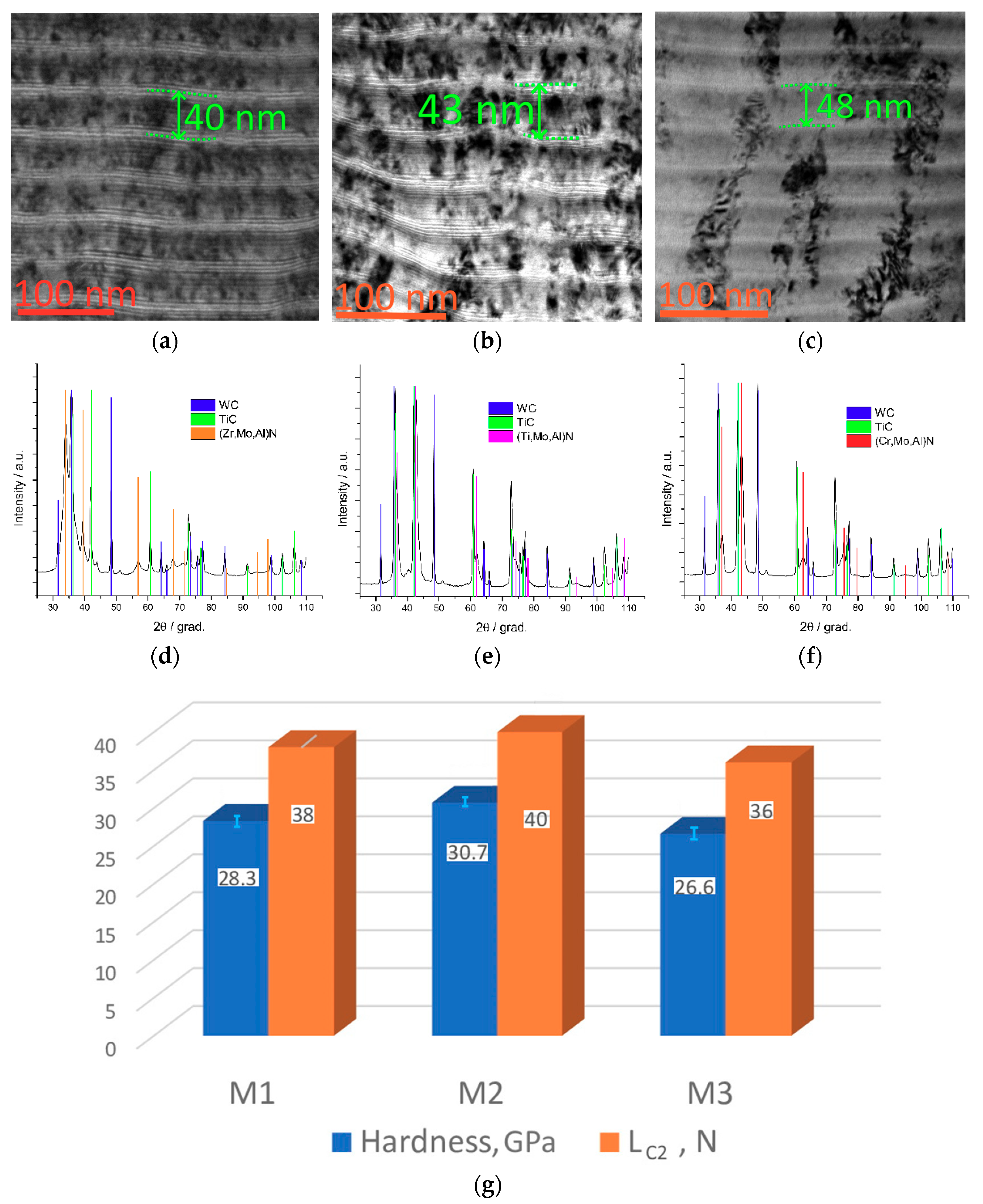
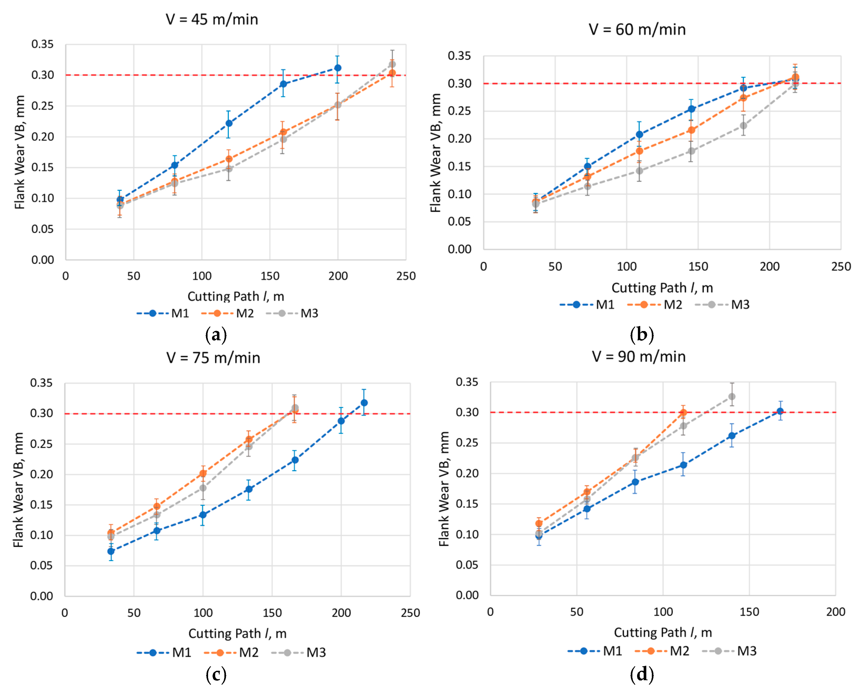
3.1. Investigation of the Mechanical Properties of the Coatings and Wear Resistance of Coated Cutting Tools

The coatings under consideration had almost identical nanolayer periods λ: 40, 43, and 48 nm (for Coatings M1, M2, and M3, respectively) (Figure 1a–c).
The phases were identified using PDF standard diffraction cards with the reference codes: no. 03-065-2899, 00-038-1420, and 00-031-1493. Judging by the obtained data on the parameters of the crystal structures, these coatings represent cubic solid solutions of nitrides (type B1): (Zr,Mo,Al)N, (Ti,Mo,Al)N, and (Cr,Mo,Al) N, respectively. The XRD phase analysis of the coatings revealed the presence of WC and TiC together with substrate phases (Figure 1d–f). The cubic solid solutions had the same structural type, cF8/2, and differed only in the lattice parameters. Table 1 shows the cubic nitride phases of the coating with the calculated lattice parameters. When comparing the lattice parameters of the coating phases and nitride phases without Mo and Al, the following was obtained: for (Cr,Mo,Al)N, the lattice parameter increased relative to the CrN phase (a = 4.149), while for (Ti,Mo,Al)N and (Zr,Mo,Al)N, the lattice parameter decreased compared to the TiN (a = 4.241) and ZrN (a = 4.574) phases, respectively.
Judging by the intensity of the diffraction lines in the (Zr,Mo,Al)N coating, the predominant grain orientation is observed—<111>, (Figure 1d). The texture is also clearly visible on SAED from this coating. On the (Ti,Mo,Al)N and (Cr,Mo,Al)N coatings, the grain texture is not so pronounced.
The XRD phase analysis of the coatings revealed the presence of a solid solution phase of nitrides ((Zr,Mo,Al)N, (Ti,Mo,Al)N, and (Cr,Mo,Al)N, respectively) together with substrate phases of WC and TiC (Figure 1d–f).
The highest hardness was detected for Coating M2 (30.70 ± 1.2 GPa); the hardness of Coating M1 was slightly lower (28.30 ± 0.70 GPa), and Coating M3 had the lowest hardness (26.60 ± 1.3 GPa) (Figure 1g). For all three coatings under consideration, the fracture threshold stress values in scratch testing were considerably high (36–40 N). In general, it can be argued that, in terms of the hardness and the fracture threshold stress value in scratch testing, the coatings under consideration have fairly close properties.
The wear resistance of coated metal-cutting tools was studied at cutting speeds of 45, 60, 75, and 90 m/min (see Figure 2). It should be noted that, at the cutting speed of 45 m/min, the tool with Coating M1 demonstrated the highest wear intensity; then, when the cutting speed was 60 m/min, at the initial stage of cutting, the highest wear intensity was also detected for the tool with Coating M1. Closer to the moment when the wear criterion is reached, the wear intensity for all three samples became almost equal. With a further increase in cutting speed up to 75 and 90 m/min, there was a noticeable change in the trends of wear on the tools with different coatings. At the given cutting speeds, the lowest wear intensity was detected for the tool with Coating M1. The average value of flank wear for the tool with Coating M1 was approximately 30% less than for the tools with Coatings M2 and M3. The tools with Coating M2 and M3 demonstrated almost equal values of wear intensity at cutting speeds of 45–90 m/min. The tool with Coating M3 had an insufficient advantage in terms of wear intensity compared to the tool with Coating M2. It should be noted that the tool with Coating M2, characterized by the highest hardness and the highest fracture threshold stress value in scratch testing, demonstrated the lowest wear resistance in the given series of tests. Such an effect can occur, as with an increase in the cutting speed, the temperature in the cutting zone rises [23,24,25,78,79,80]. In turn, the increase in temperature leads to the intensification of the oxidation and diffusion processes. While at lower temperatures in the cutting zone, the prevailing wear mechanism is adhesive–fatigue and adhesive wear, with an increase in the cutting speed, the oxidation and diffusion factors become increasingly important [23,24,25,26,27,78]. At the same time, the tribologically active oxide films can be formed, which have a positive effect on the cutting conditions [18,19,20,21,22]. According to earlier studies, while at a temperature of 400 °C, the minimal value of the coefficient of friction was detected on the samples with Coatings M2 and M3; then, with an increase in temperature to 550 °C and higher, the lowest value of the coefficient of friction was detected for the sample with Coating M1 [63,65]. The results, obtained during the turning of 1045 steel using the tools with the coatings under consideration, did not detect the formation of any noticeable amount of oxide during the cutting process.
The patterns of wear and fracture on the coatings under consideration after cutting were considered. Lamellas, cut from the area of the coating fracture boundary on the wear crater boundary farthest from the cutting edge, were selected for the study (see Figure 3).

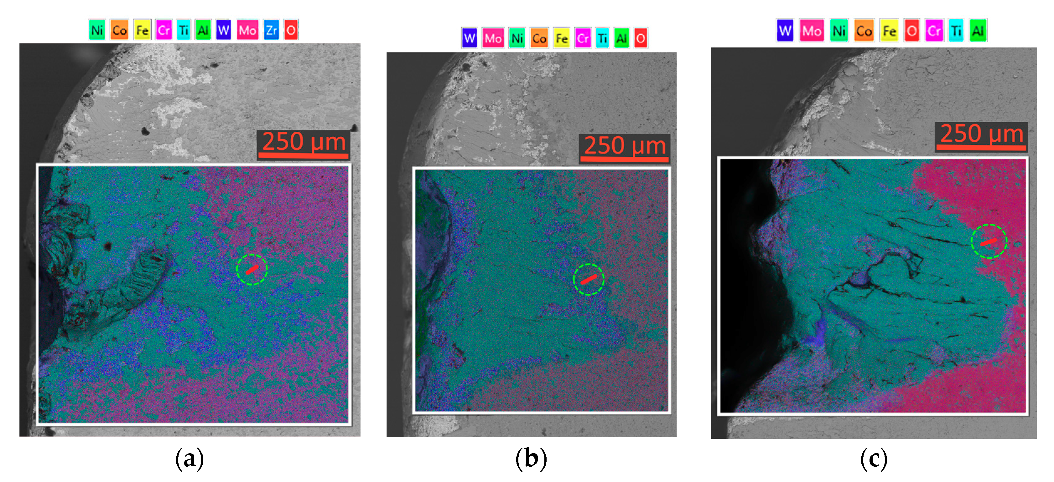
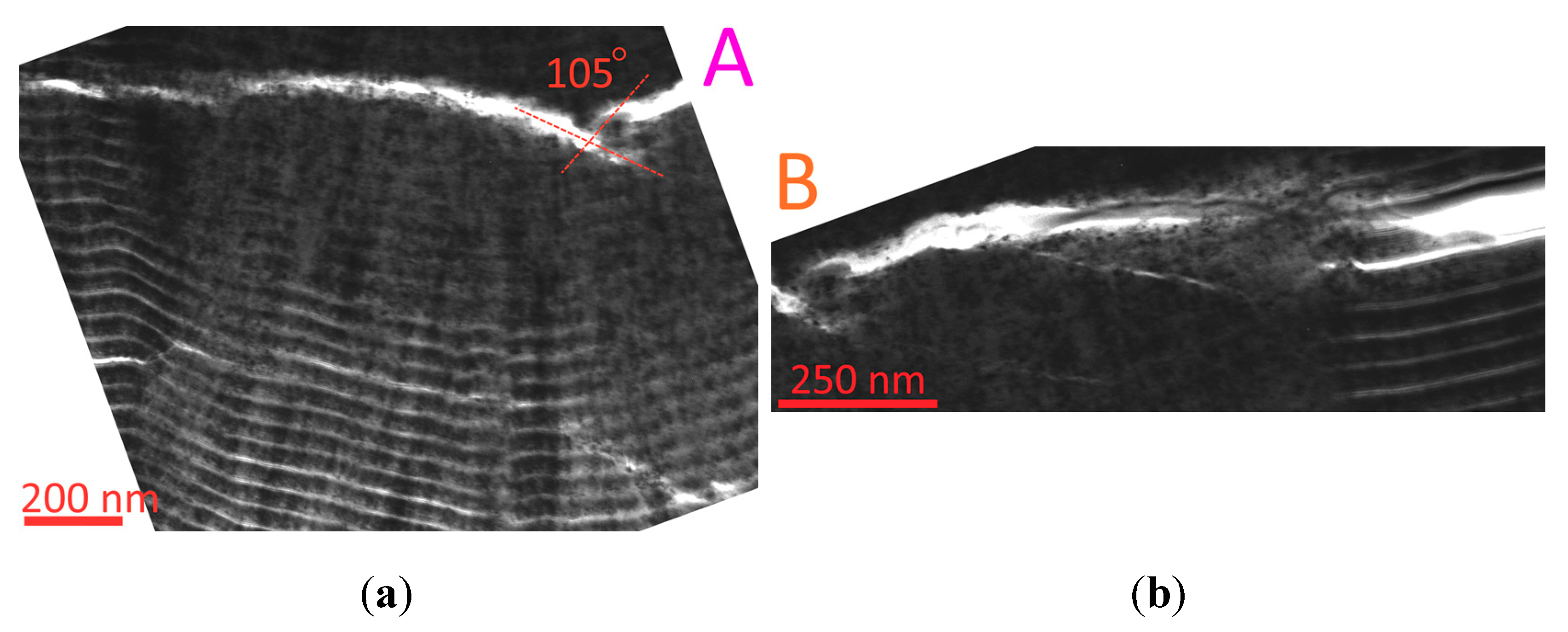
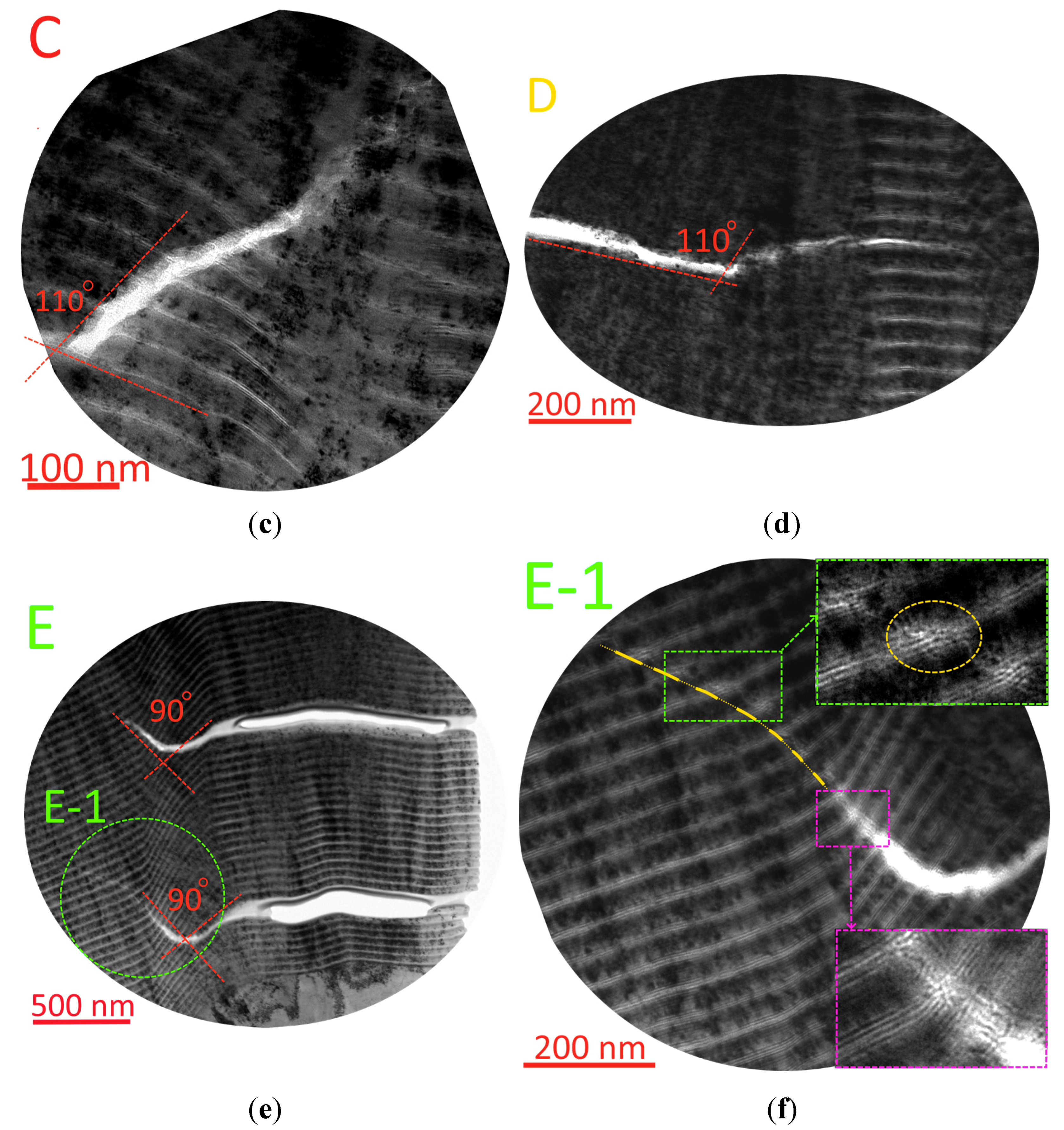
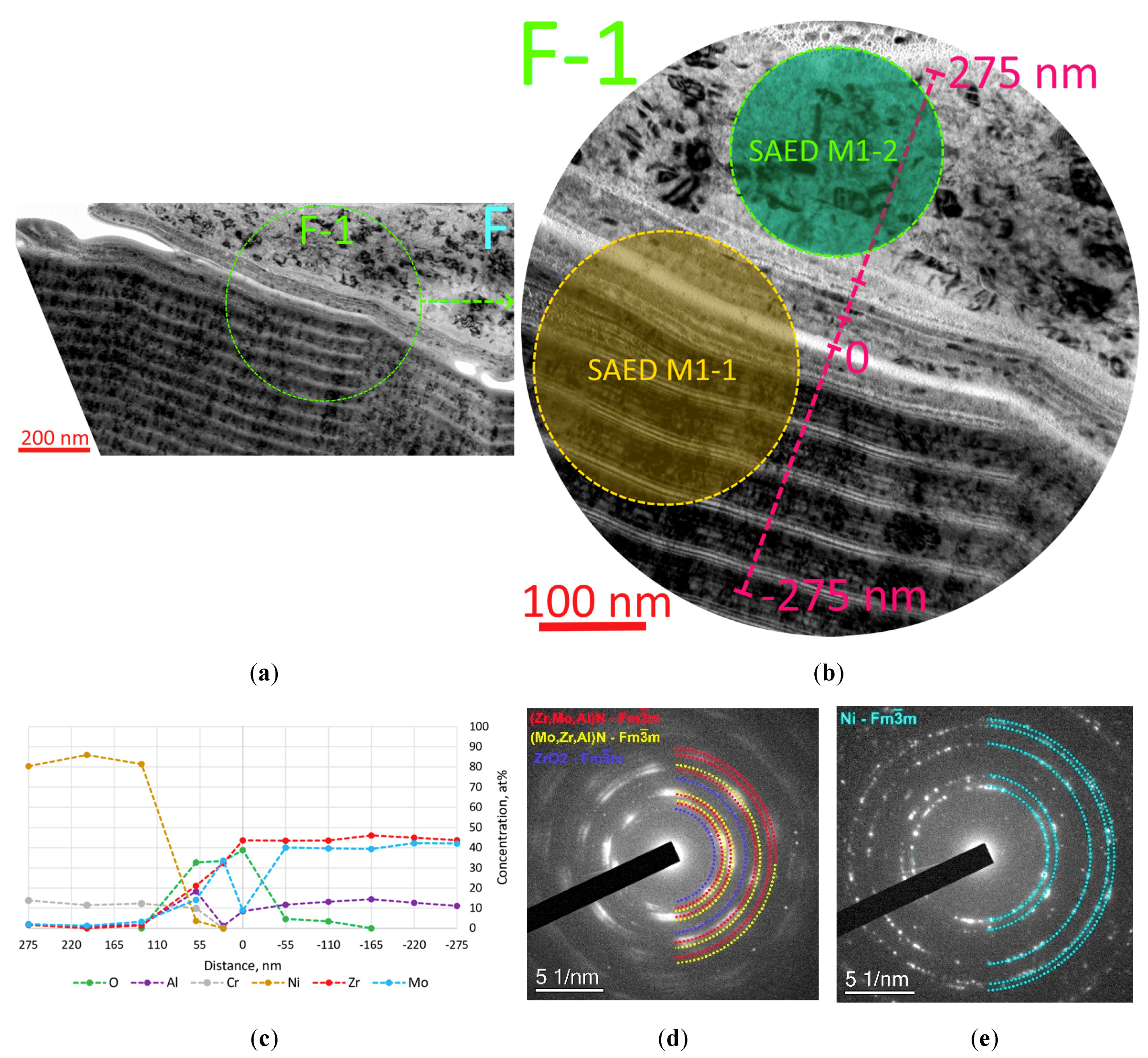
3.2. Investigation of the Processes of Fracture, Diffusion, and Oxidation in Zr–ZrN–(Zr,Mo,Al)N (Coating M1)

There was a consideration of the pattern of wear in Coating M1. Typical areas were selected on a cut-out lamella for further studies (Figure 4). The structure of Coating M1 contained considerably extended delaminations between nanolayers, which at the edges turn into the cracks that cut through the nanolayers. Such delaminations can be associated both with a high level of compressive residual stresses and with insufficient strength of the cohesive bond between nanolayers [80,81,82,83,84,85]. While such delaminations undoubtedly weaken the overall structure of the coating, they can also play some positive role by reducing the values of internal stresses [80,81,82,83,84,85].
The pattern of cracking in Coating M1 was considered in detail (Figure 5). During the growth of delaminations, bond bridges between the nanolayers were retained (Figure 5a,b). The very nanolayers demonstrated sufficient strength, and no formation of through-transverse cracks was detected. Thus, a sequence of the nanolayers between two delaminations was essentially a curved multilayer elastic beam, resembling a semi-elliptical leaf spring, the sheets of which are tightly fastened to each other. During the cutting process, the center of the described “curved beam” was subjected to a variable load, which caused deflection. As a result, the edges of the given “curved beam,” coinciding with the boundary of delamination, acted on the coating with a certain force. Such a cyclic action led to the formation of fatigue cracks, exhibited in Figure 5c–f. According to the preliminary analysis, the angle between the direction in which delamination grew and the initial direction in which a subsidiary crack propagated was 90–110° (see Figure 5a,c–e). It should be noted that it was the initial direction of the crack propagation which was considered, and that the described direction can change with further movement of the crack tip. Such close values of the angles may indicate that the conditions for the formation of cracks in different parts of the sample under consideration were fairly close, that is, the physical conditions leading to the formation of cracks. Another typical feature of the formation of cracks in Coating M1 was the discrete nature of their propagation trajectories detected in some areas. In particular, Figure 5f depicts a fully open crack transforming into a discrete one; when the crack propagation trajectory intersected the nanolayers that are lighter in contrast (accordingly, with a high content of aluminum), gaps (relaxations) were formed in the material structure (in particular, the area circled by the yellow dotted line in the inset in the upper right corner of Figure 5f). At the same time, there were no noticeable changes in the structure of the nanolayers that are darker in contrast (with a prevailing content of Zr and Mo). With the further propagation of the crack, the described gaps (relaxations) merged, and as a result, the crack moved (see the inset in the lower right corner of Figure 5f). A similar mechanism of crack propagation in the structure, combining harder and more plastic phases, was described in [80,81,82,83,84,85,86].
The area of contact between the flow of the material being machined (an adherent on the lamella) and the coating surface (Area F in Figure 4, exhibited in Figure 6a) was also investigated. There was a transition layer about 100 nm thick between the coating surface and the adherent of the material being machined. The elemental composition of the layer, as well as the phase composition (SAED) of the areas of the adherent adjacent to the coating and the coating layers adjacent to the adherent, were considered (the localization of the line of study of the elemental composition and the SAED analysis are exhibited in Figure 6b). The analysis of the distribution of elements detected a noticeable increase in the oxygen content in the region of the transition layer under consideration (Figure 6c). Accordingly, oxide phases could be detected in the specified layer. Given the high content of Zr and Mo in the layer under consideration, the oxides of Zr and Mo were primarily expected.
The above assumptions were partially confirmed by the results of the SAED analysis (Figure 6d,e).
The identification of the adherent revealed the presence of metallic nickel (Figure 6e), and two phases of solid solution of nitrides were detected in the coating—(Zr,Mo,Al)N, with a slightly larger lattice parameter compared to the second detected phase, (Mo,Zr,Al)N (Figure 6d). The SAED ring distribution pattern also indicated a slight texturization of the grains of the nitride phases. In addition to the two nitride phases, a small amount of cubic zirconium oxide phase was detected in the coating at the interface with the adherent, which correlated well with the distribution of oxygen and zirconium at the interface. While the layer under consideration also contained regions with an increased content of Mo and Al (see the local peaks of Mo and Al in Figure 6c), no oxide phases of Mo and Al were detected. Such a result may indicate either the absence of oxides of molybdenum and aluminum in the layer under consideration or the presence of an amount of them too small for reliable identification with the methods used. Thus, it is clear that during the cutting process, a transition layer about 100 nm thick was formed between the flow of the material being machined and the surface of Coating M1. The described transition layer included zirconium oxide ZrO2 and, possibly, small amounts of oxides of molybdenum and aluminum (based on the presence of the regions with an increased content of Mo and Al in the layer under consideration). No diffusion of nickel into the coating was detected. It is possible that the considered oxide layer inhibited the diffusion processes. At the same time, the studies detected the diffusion of zirconium into the material being machined to a depth not exceeding 150 nm, and the diffusion of molybdenum and aluminum to a similar depth. Since the studies also revealed the diffusion of oxygen into the material being machined, it can be assumed there was a diffusion of metals from the oxide layer or a direct diffusion of metal oxides. This issue requires additional study, as the available equipment does not allow reliable phase analysis in such small regions.
Thus, the considered oxide layer performed barrier functions with respect to the diffusion of nickel into the coating due to the low tendency of nickel to form oxides and the actual absence of nickel in the layer under consideration. At the same time, zirconium, molybdenum, and aluminum diffused into the material being machined, as pure zirconium, molybdenum, and aluminum or their oxides were detected in the layer under consideration.

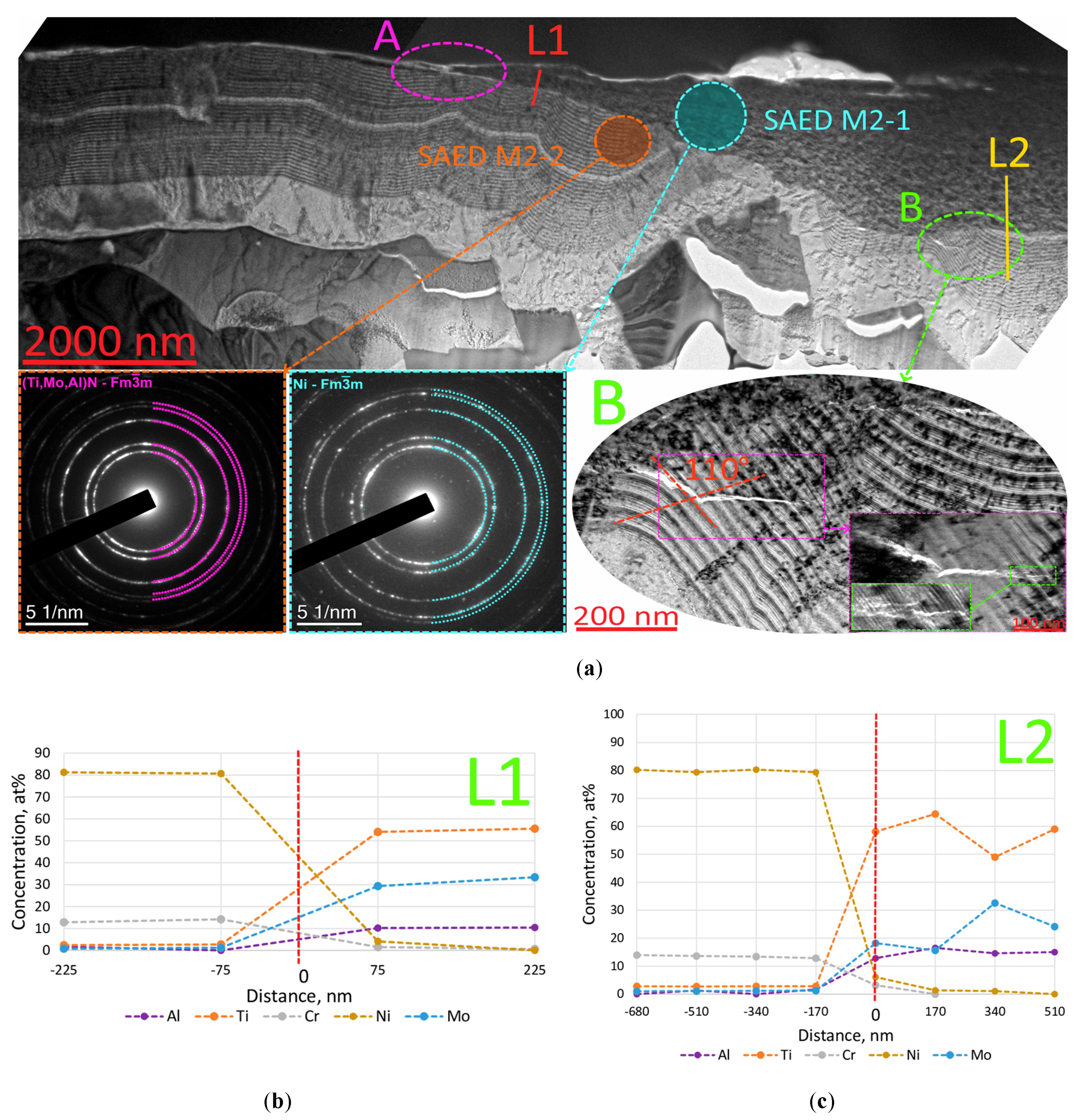
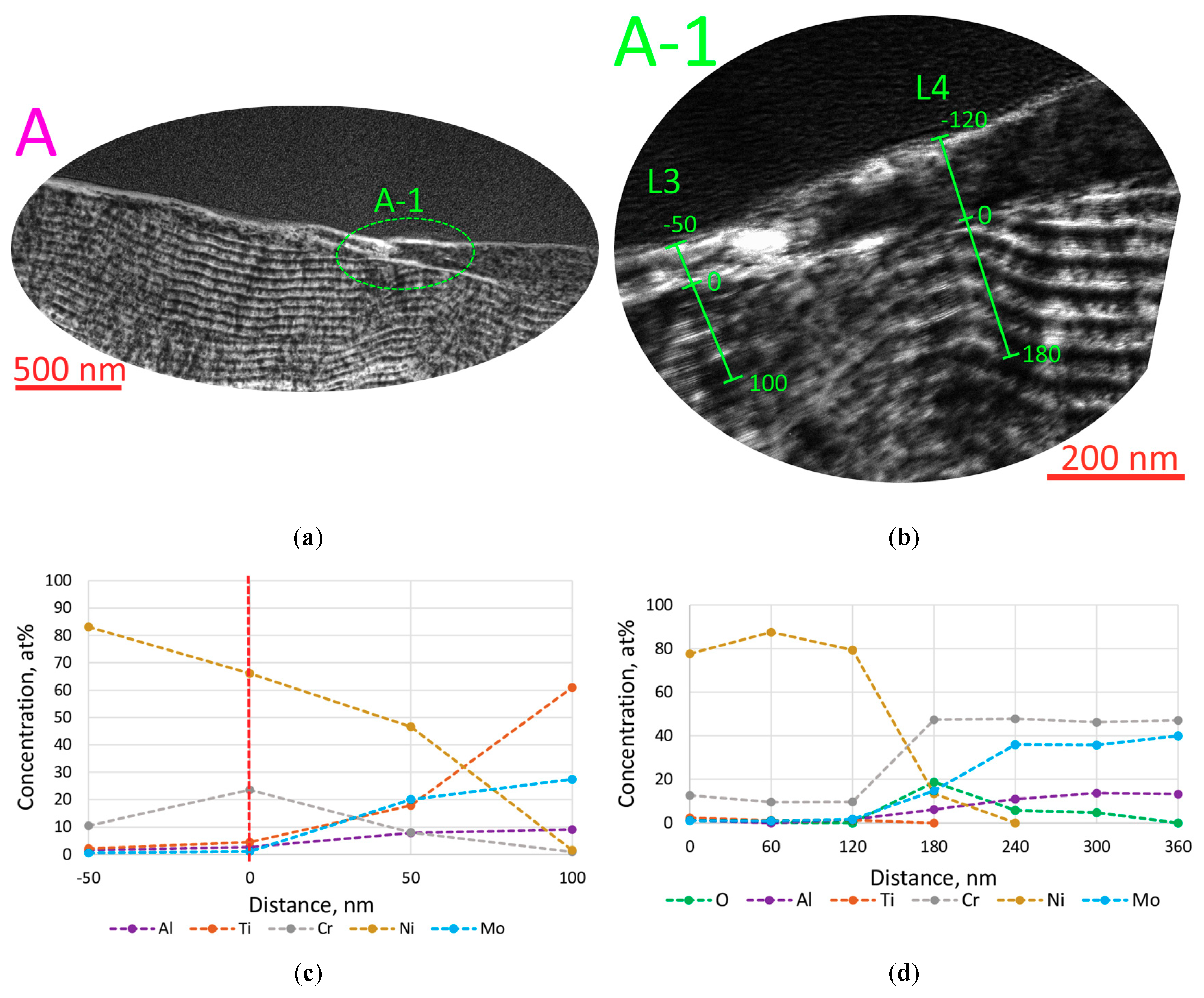
3.3. Investigation of the Processes of Fracture, Diffusion, and Oxidation in Ti–TiN–(Ti,Mo,Al)N (Coating M2)

There was a consideration of the pattern of wear in Coating M2. Figure 7a exhibits the general view of a cut-out lamella. The SAED analysis from the coating area adjacent to an adherent of the material being machined revealed a uniquely identified phase of cubic solid solution of c-(Ti,Mo,Al)N. No other phases, including oxide phases, were detected. The area of the adherent was identified as metallic nickel.
According to the results of the analysis of elemental composition along lines L1 and L2 (depicted in Figure 7a, with the results of the analysis presented in Figure 7b,c), there were no signs of oxygen in the area of the adherent–coating interface. The data obtained correlated well with the SAED data.
Unlike Coating M1, the coating under consideration demonstrated no active formation of delaminations between the nanolayers. The analysis of the existing cracks revealed some common features of the cracking processes in Coatings M1 and M2. Figure 7a exhibits delamination and a crack extending from it and cutting through the nanolayers (Area B). It should be noted that the angle between the propagation trajectories of the delamination and the crack was 110°, which is almost identical to the trend considered in the analysis of Coating M1.
Since the absence of oxygen and, accordingly, the absence of oxides in the studied area between the coating surface and the adherent of the material being machined required additional confirmation, the local Area A was studied (the location of Area A is indicated in Figure 7a, and the results of the analysis are presented in Figure 8). The access of oxygen to the areas considered earlier could be hindered, and any formation of oxides could thus be prevented, so the area of the outer boundary of the adherent (Area A-1 in Figure 8b) was chosen for further studies. It is clear there was a possibility of oxygen access in the region, and, accordingly, the presence of oxide phases could be predicted. However, the analysis of the elemental composition of the considered areas along lines L3 and L4 (Figure 8c,d) revealed the absence of oxygen at the adherent–coating interface (at least, the absence of sufficient amounts of oxygen for its identification). Thus, it can be argued there was no active formation of oxides in the considered area of Coating M2 under the cutting conditions specified. In particular, the studies detected the diffusion of nickel and chromium from the material being machined into the coating to a depth of 60–100 nm, and the diffusion of elements of the coating (primarily titanium) into the material being machined to a depth of 60–170 nm.

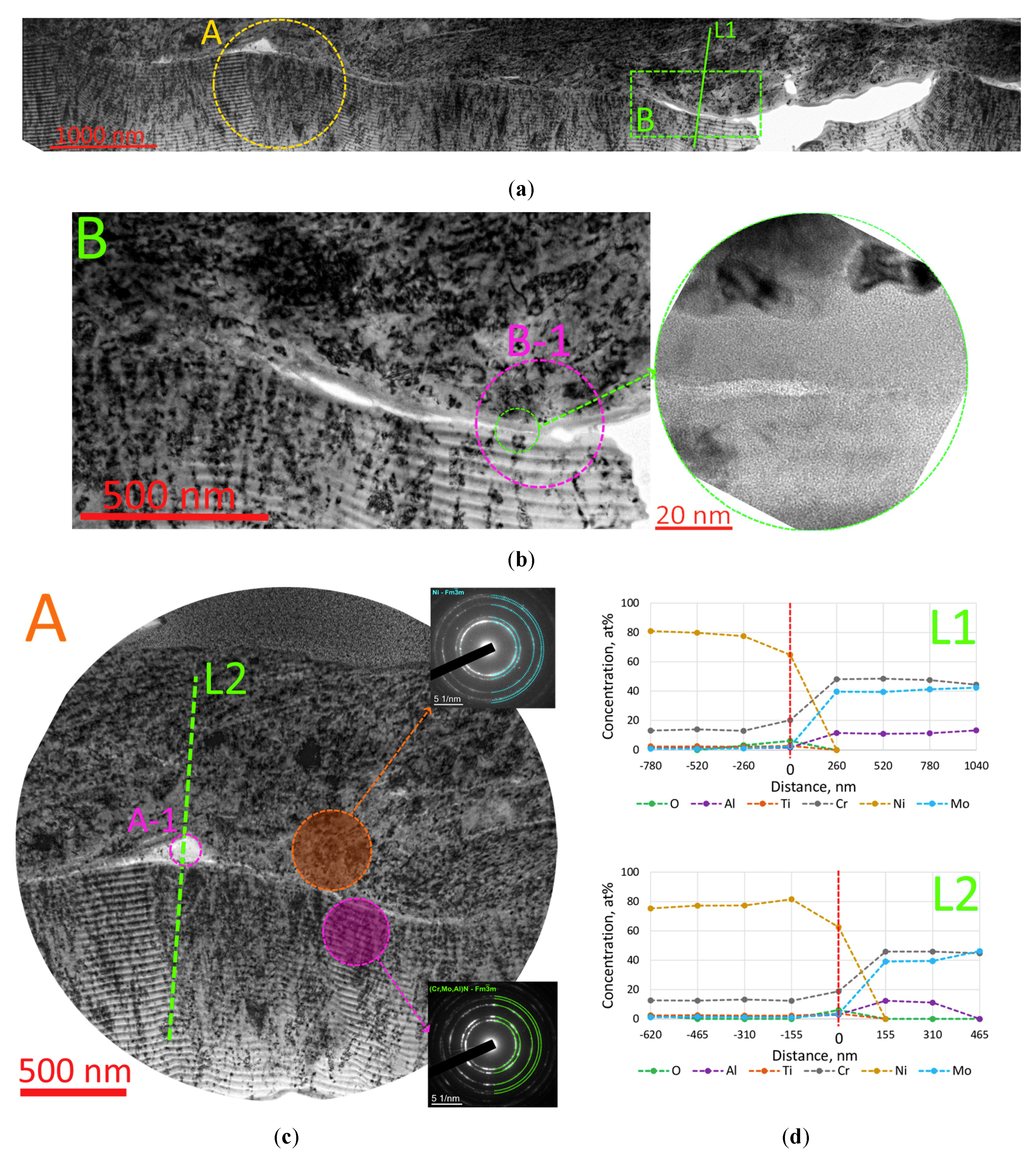
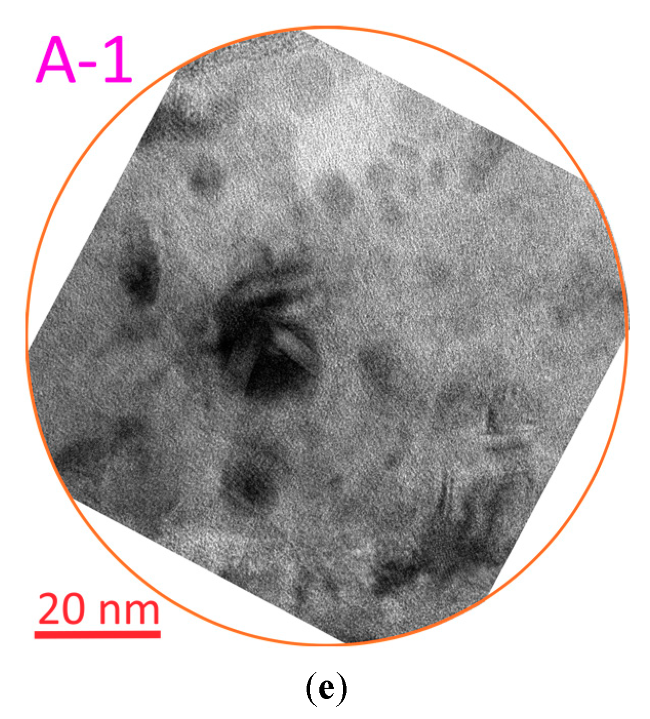
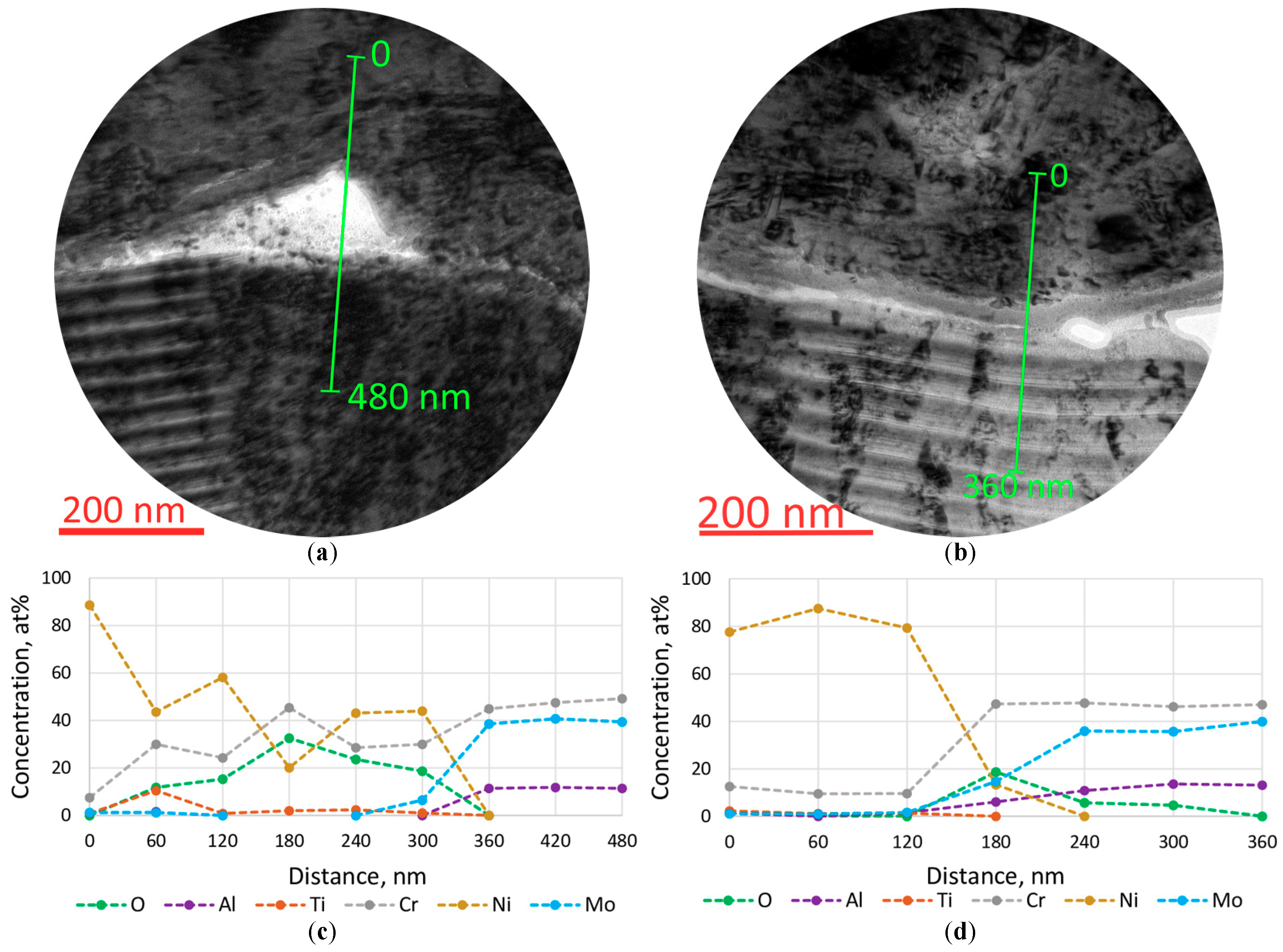
3.4. Investigation of the Processes of Fracture, Diffusion, and Oxidation in Cr–CrN–(Cr, Mo, Al)N (Coating M3)

Figure 9a depicts the general view of the lamella under study. Areas A and B were chosen for further investigation, since in these areas, the coating clearly contained a transition layer that resembled the oxide layer studied in Coating M1. The study of the elemental composition along lines L1 and L2 detected the presence of a certain amount of oxygen in the indicated layer, in both Area A and Area B (Figure 9d). The analysis of the HTEM images of the layer under study (Figure 9b, the inset on the right and Area A-1, Figure 9e) revealed the absence of crystalline grains in the region. This indicated a more likely amorphous structure, which may be typical for assumed oxides. However, the SAED analysis did not detect any oxide phases (Figure 9c). Such a contradiction may occur due to the extremely small dimensions of the areas under study and, accordingly, the impossibility of obtaining SAED data with the required accuracy. The coating phase from the near-interface region was identified as a cubic solid solution of c-(Cr,Mo,Al)N. The area of the adherent was identified as metallic nickel. Nickel diffusion into the coating was detected to a depth of 155–260 nm, which was the maximum depth for the three samples under consideration.
To further study the composition of the transition layer in Coating M3, the change of the elemental composition in local Areas A-1 and B-1 was analyzed (Figure 10). The results of the analysis made it possible to determine with high reliability the presence of a sufficiently high oxygen content in the areas under consideration. An important feature of the graphs obtained is the practical congruence of the oxygen and chromium graphs, which assumes the presence of, namely, chromium oxide in the layer under consideration.

4. Conclusions

1. In the Zr-ZrN-(Zr,Mo,Al)N coating, two cubic nitride phases were formed—(Zr,Mo,Al)N (the ZrN-based solid solution) and (Mo,Zr,Al)N (the MoN-based solid solution)—while in the other coatings, there was only a single cubic nitride phase—(Ti,Mo,Al)N (the TiN-based solid solution) or (Cr,Mo,Al)N (the CrN-based solid solution).
2. At the cutting speed of 45 m/min, the tool with the Zr-ZrN-(Zr,Mo,Al)N coating had the highest wear intensity, while at the cutting speed of 60 m/min, the wear intensity was almost the same for all three samples. With a further increase in the cutting speed to 75 and 90 m/min, the tool with the Zr-ZrN-(Zr,Mo,Al)N coating demonstrated the lowest wear intensity. At the cutting speeds of 75 and 90 m/min, the average flank wear for the tool with the Zr-ZrN-(Zr,Mo,Al)N coating was approximately 30% lower compared to the tools with other coatings under consideration.
3. The investigation of the patterns of wear on the tools with the coatings under study after cutting at the speed of 90 m/min detected the presence of a reliably identified transition layer of zirconium oxide at the interface between the Zr-ZrN-(Zr,Mo,Al)N coating and the material being machined. No such transition layer was detected for the Ti-TiN-(Ti,Mo,Al)N coating, and for the Cr-CrN-(Cr,Mo,Al)N coating, a transition layer was detected, which, with a high degree of certainty, could be oxide of chromium.
4. It can be assumed that there is a certain relationship between the forming transition oxide layer and the depth of nickel diffusion into the coating. For the Zr-ZrN-(Zr,Mo,Al)N coating, no nickel diffusion was detected in the region with the transition layer. For the Cr-CrN-(Cr,Mo,Al)N coating, despite the identical thickness of the transition layer, the diffusion of nickel into the coating to a depth not exceeding 260 nm was detected. Thus, it can be assumed that the transition layer based on zirconium oxide (ZrO2) had significantly better barrier properties with respect to the nickel diffusion flux compared to the transition layer based on chromium oxide.

Author Contributions

Conceptualization, S.G. and A.V.; methodology, A.V. and F.M.; validation, A.V., O.Y. and N.K.; investigation, F.M., N.A., A.S. (Alexander Shein), A.S. (Anton Seleznev) and O.K. and S.K.; resources, S.G.; data curation, N.A., A.S. (Alexander Shein), A.S. (Anton Seleznev), O.K., S.K. and P.P.; writing—original draft preparation, A.V. and F.M.; project administration, P.P.; funding acquisition, S.G. All authors have read and agreed to the published version of the manuscript.

Funding

This research was funded by the state assignment of the Ministry of Science and Higher Education of the Russian Federation, Project No. 0707-2020-0025.

Institutional Review Board Statement

Not applicable.

Informed Consent Statement

Not applicable.

Data Availability Statement

Not applicable.

Acknowledgments

The study used the equipment from the Centre for collective use of Moscow State Technological University STANKIN (agreement No. 075-15-2021-695, 26 July 2021). The coating structure was investigated using the equipment of the Centre for collective use of scientific equipment “Material Science and Metallurgy”, purchased with the financial support of the Ministry of Science and Higher Education of the Russian Federation (GK 075-15-2021-696).

Conflicts of Interest

The authors declare no conflict of interest.

References

  1. Bobzin, K. High-performance coatings for cutting tools. CIRP J. Manuf. Sci. Technol. 2017, 18, 1–9. [Google Scholar] [CrossRef]
  2. Baptista, A.; Silva, F.; Porteiro, J.; Míguez, J.; Pinto, G. Sputtering physical vapour deposition (PVD) coatings: A critical review on process improvement andmarket trend demands. Coatings 2018, 8, 402. [Google Scholar] [CrossRef]
  3. Qadir, M.; Li, Y.; Wen, C. Ion-substituted calcium phosphate coatings by physical vapor deposition magnetron sputtering for biomedical applications: A review. Acta Biomater. 2019, 89, 14–32. [Google Scholar] [CrossRef] [PubMed]
  4. Selvakumar, N.; Barshilia, H.C. Review of physical vapor deposited (PVD) spectrally selective coatings for mid- and high-temperature solar thermal applications. Sol. Energy Mater. Sol. Cells 2012, 98, 1–23. [Google Scholar] [CrossRef]
  5. Kamalisarvestani, M.; Saidur, R.; Mekhilef, S.; Javadi, F.S. Performance, materials and coating technologies of thermochromic thin films on smart windows. Renew. Sustain. Energy Rev. 2013, 26, 353–364. [Google Scholar] [CrossRef]
  6. Mehran, Q.M.; Fazal, M.A.; Bushroa, A.R.; Rubaiee, S. A Critical Review on Physical Vapor Deposition Coatings Applied on Different Engine Components. Crit. Rev. Solid State Mater. Sci. 2018, 43, 158–175. [Google Scholar] [CrossRef]
  7. Pogrebnjak, A.; Smyrnova, K.; Bondar, O. Nanocomposite multilayer binary nitride coatings based on transition and refractory metals: Structure and properties. Coatings 2019, 9, 155. [Google Scholar] [CrossRef]
  8. Ezugwu, E.O.; Wang, Z.M.; Machado, A.R. The machinability of nickel-based alloys: A review. J. Mater. Process. Technol. 1998, 86, 1–16. [Google Scholar] [CrossRef]
  9. Thakur, A.; Gangopadhyay, S. State-of-the-art in surface integrity in machining of nickel-based super alloys. Int. J. Mach. Tools Manuf. 2016, 100, 25–54. [Google Scholar] [CrossRef]
  10. Ezugwu, E.O. Key improvements in the machining of difficult-to-cut aerospace superalloys. Int. J. Mach. Tools Manuf. 2005, 45, 1353–1367. [Google Scholar] [CrossRef]
  11. Grigoriev, S.N.; Gurin, V.D.; Volosova, M.A.; Cherkasova, N.Y. Development of residual cutting tool life prediction algorithm by processing on CNC machine tool. Mater. Werkst. 2013, 44, 790–796. [Google Scholar] [CrossRef]
  12. Grigoriev, S.N.; Sinopalnikov, V.A.; Tereshin, M.V.; Gurin, V.D. Control of parameters of the cutting process on the basis of diagnostics of the machine tool and workpiece. Meas. Tech. 2012, 55, 555–558. [Google Scholar] [CrossRef]
  13. Devillez, A.; Schneider, F.; Dominiak, S.; Dudzinski, D.; Larrouquere, D. Cutting forces and wear in dry machining of Inconel 718 with coated carbide tools. Wear 2007, 262, 931–942. [Google Scholar] [CrossRef]
  14. Hartung, P.D.; Kramer, B.M.; von Turkovich, B.F. Tool Wear in Titanium Machining. CIRP Ann. Manuf. Technol. 1982, 31, 75–80. [Google Scholar] [CrossRef]
  15. Jawaid, A.; Sharif, S.; Koksal, S. Evaluation of wear mechanisms of coated carbide tools when face milling titanium alloy. J. Mater. Process. Technol. 2000, 99, 266–274. [Google Scholar] [CrossRef]
  16. Grigoriev, S.; Vereschaka, A.; Milovich, F.; Andreev, N.; Bublikov, J.; Sitnikov, N.; Sotova, C.; Kutina, N. Investigation of wear mechanisms of multilayer nanostructured wear-resistant coatings during turning of steel. Part 2: Diffusion, oxidation processes and cracking in Ti-TiN-(Ti,Cr,Mo,Al)N coating. Wear 2021, 486, 204096. [Google Scholar] [CrossRef]
  17. Aizawa, T.; Mitsuo, A.; Yamamoto, S.; Sumitomo, T.; Muraishi, S. Self-lubrication mechanism via the in situ formed lubricious oxide tribofilm. Wear 2005, 259, 708–718. [Google Scholar] [CrossRef]
  18. Fox-Rabinovich, G.S.; Yamamoto, K.; Beake, B.D.; Kovalev, A.I.; Aguirre, M.H.; Veldhuis, S.C.; Dosbaeva, G.K.; Wainstein, D.L.; Biksa, A.; Rashkovskiy, A. Emergent behavior of nano-multilayered coatings during dry high-speed machining of hardened tool steels. Surf. Coat. Technol. 2010, 204, 3425–3435. [Google Scholar] [CrossRef]
  19. Fox-Rabinovich, G.S.; Veldhuis, S.C.; Dosbaeva, G.K.; Yamamoto, K.; Kovalev, A.I.; Wainstein, D.L.; Gershman, I.S.; Shuster, L.S.; Beake, B.D. Nanocrystalline coating design for extreme applications based on the concept of complex adaptive behaviour. J. Appl. Phys. 2008, 103, 083510. [Google Scholar] [CrossRef]
  20. Endrino, J.L.; Fox-Rabinovich, G.S.; Gey, C. Hard AlTiN, AlCrN PVD coatings for machining of austenitic stainless steel. Surf. Coat. Technol. 2006, 200, 6840–6845. [Google Scholar] [CrossRef]
  21. Fox-Rabinovich, G.S.; Yamomoto, K.; Veldhuis, S.C.; Kovalev, A.I.; Dosbaeva, G.K. Tribological adaptability of TiAlCrN PVD coatings under high performance dry machining conditions. Surf. Coat. Technol. 2005, 200, 1804–1813. [Google Scholar] [CrossRef]
  22. Beake, B.D.; Fox-Rabinovich, G.S. Progress in high temperature nanomechanical testing of coatings for optimising their performance in high speed machining. Surf. Coat. Technol. 2014, 255, 102–111. [Google Scholar] [CrossRef]
  23. Salomon, C.J. Process for Machining Metals of Similar Acting Materials When Being Worked by Cutting Tools. German Patent No. 523594, 27 April 1931. [Google Scholar]
  24. Boothroyd, G.; Knight, W.A. Fundamentals of Machining and Machine Tools; CRC Press: Boca Raton, FL, USA, 2006. [Google Scholar]
  25. Kuzin, V.V.; Grigoriev, S.N.; Volosova, M.A. The role of the thermal factor in the wear mechanism of ceramic tools: Part 1. Macrolevel. J. Frict. Wear 2014, 35, 505–510. [Google Scholar] [CrossRef]
  26. Loladze, T.N. Of the theory of diffusion wear. CIRP Ann.-Manuf. Technol. 1981, 30, 71–76. [Google Scholar] [CrossRef]
  27. Loladze, T.N. Nature of brittle failure of cutting tool. CIRP Ann.-Manuf. Technol. 1975, 24, 13–16. [Google Scholar]
  28. Singh, A.; Ghosh, S.; Aravindan, S. Flank wear and rake wear studies for arc enhanced HiPIMS coated AlTiN tools during high speed machining of nickel-based superalloy. Surf. Coat. Technol. 2020, 381, 125190. [Google Scholar] [CrossRef]
  29. Bouzakis, K.D.; Michailidis, N.; Skordaris, G.; Bouzakis, E.; Biermann, D.; M’Saoubi, R. Cutting with coated tools: Coating technologies, characterization methods and performance optimization. CIRP Ann.-Manuf. Technol. 2012, 61, 703–723. [Google Scholar] [CrossRef]
  30. Tkadletz, M.; Schalk, N.; Daniel, R.; Keckes, J.; Czettl, C.; Mitterer, C. Advanced characterization methods for wear resistant hard coatings: A review on recent progress. Surf. Coat. Technol. 2016, 285, 31–46. [Google Scholar] [CrossRef]
  31. Grigoriev, S.; Peretyagin, P.; Smirnov, A.; Solis, W.; Diaz, L.A.; Fernandez, A.; Torrecillas, R. Effect of graphene addition on the mechanical and electrical properties of Al2O3-SiCw ceramics. J. Eur. Ceram. Soc. 2017, 37, 2473–2479. [Google Scholar] [CrossRef]
  32. Suna, J.; Musil, J.; Dohnal, P. Control of macrostress s in reactively sputtered Mo−Al−N films by total gas pressure. Vacuum 2006, 80, 588–592. [Google Scholar] [CrossRef]
  33. Xu, J.; Ju, H.; Yu, L. Microstructure, oxidation resistance, mechanical and tribological properties of Mo-Al-N films by reactive magnetron sputtering. Vacuum 2014, 103, 21–27. [Google Scholar] [CrossRef]
  34. Klimashin, F.F.; Euchner, H.; Mayrhofer, P.H. Computational and experimental studies on structure and mechanical properties of Mo-Al-N. Acta Mater. 2016, 107, 273–278. [Google Scholar] [CrossRef]
  35. Yang, J.F.; Yuan, Z.G.; Liu, Q.; Wang, X.P.; Fang, Q.F. Characterization of Mo–Al–N nanocrystalline films synthesized by reactive magnetron sputtering. Mater. Res. Bull. 2009, 44, 86–90. [Google Scholar] [CrossRef]
  36. Tomaszewski, L.; Gulbinski, W.; Urbanowicz, A.; Suszko, T.; Lewandowski, A.; Gulbinski, W. TiAlN based wear resistant coatings modified by molybdenum addition. Vacuum 2015, 121, 223–229. [Google Scholar] [CrossRef]
  37. Yousaf, M.I.; Pelenovicha, V.O.; Yangc, B.; Liua, C.S.; Fu, D.J. Effect of bilayer period on structural and mechanical properties of nanocomposite TiAlN/MoN multilayer films synthesized by cathodic arc ion-plating. Surf. Coat. Technol. 2015, 282, 94–102. [Google Scholar] [CrossRef]
  38. Bobzin, K.; Brögelmann, T.; Kalscheuer, C.; Stahl, K.; Lohner, T.; Yilmaz, M. (Cr,Al)N and (Cr,Al,Mo)N hard coatings for tribological applications under minimum quantity lubrication. Tribol. Int. 2019, 140, 105817. [Google Scholar] [CrossRef]
  39. Gilewicz, A.; Warcholinski, B. Deposition and characterisation of Mo2N/CrN multilayer coatings prepared by cathodic arc evaporation. Surf. Coat. Technol. 2015, 279, 126–133. [Google Scholar] [CrossRef]
  40. Ju, H.; Yu, D.; Xu, J.; Yu, L.; Zuo, B.; Geng, Y.; Huang, T.; Shao, L.; Ren, L.; Du, C.; et al. Crystal structure and tribological properties of Zr-Al-Mo-N composite films deposited by magnetron sputtering. Mater. Chem. Phys. 2019, 230, 347–354. [Google Scholar] [CrossRef]
  41. Sergevnin, V.S.; Blinkov, I.V.; Volkhonskii, A.O.; Belov, D.S.; Kuznetsov, D.V.; Gorshenkov, M.V.; Skryleva, E.A. Wear behaviour of wear-resistant adaptive nano-multilayered Ti-Al-Mo-N coatings. Appl. Surf. Sci. 2016, 388, 13–23. [Google Scholar] [CrossRef]
  42. Glatz, S.A.; Koller, C.M.; Bolvardi, H.; Kolozsvári, S.; Riedl, H.; Mayrhofer, P.H. Influence of Mo on the structure and the tribomechanical properties of arc evaporated Ti-Al-N. Surf. Coat. Technol. 2017, 311, 330–336. [Google Scholar] [CrossRef]
  43. Grigoriev, S.N.; Metel, A.S.; Fedorov, S.V. Modification of the structure and properties of high-speed steel by combined vacuum-plasma treatment. Met. Sci. Heat Treat. 2012, 54, 8–12. [Google Scholar] [CrossRef]
  44. Yang, K.; Xian, G.; Zhaoc, H.; Fanb, H.; Wangb, J.; Wangc, H.; Du, H. Effect of Mo content on the structure and mechanical properties of TiAlMoN films deposited on WC–Co cemented carbide substrate by magnetron sputtering. Int. J. Refract. Met. Hard Mater. 2015, 52, 29–35. [Google Scholar] [CrossRef]
  45. Glatz, S.A.; Moraes, V.; Koller, C.M.; Riedl, H.; Bolvardi, H.; Kolozsvári, S.; Mayrhofer, P.H. Effect of Mo on the thermal stability, oxidation resistance, and tribo-mechanical properties of arc evaporated Ti-Al-N coatings. J. Vac. Sci. Technol. A Vac. Surf. Films 2017, 35, 061515. [Google Scholar] [CrossRef]
  46. Klimashin, F.F.; Mayrhofer, P.H. Ab initio-guided development of super-hard Mo–Al–Cr–N coatings. Scr. Mater. 2017, 140, 27–30. [Google Scholar] [CrossRef]
  47. Bobzin, K.; Brögelmann, T.; Kalscheuer, C.; Stahl, K.; Lohner, T.; Yilmaz, M. Effects of (Cr,Al)N and (Cr,Al,Mo)N coatings on friction under minimum quantity lubrication. Surf. Coat. Technol. 2020, 402, 126154. [Google Scholar] [CrossRef]
  48. Gu, B.; Tu, J.P.; Zheng, X.H.; Yang, Y.Z.; Peng, S.M. Comparison in mechanical and tribological properties of Cr–W–N and Cr–Mo–N multilayer films deposited by DC reactive magnetron sputtering. Surf. Coat. Technol. 2008, 202, 2189–2193. [Google Scholar] [CrossRef]
  49. Bobzin, K.; Brögelmann, T.; Kalscheuer, C. Arc PVD (Cr,Al,Mo)N and (Cr,Al,Cu)N coatings for mobility applications. Surf. Coat. Technol. 2020, 384, 125046. [Google Scholar] [CrossRef]
  50. Iram, S.; Wang, J.; Cai, F.; Zhang, J.; Ahmad, F.; Liang, J.; Zhang, S. Effect of bilayer number on mechanical and wear behaviours of the AlCrN/AlCrMoN coatings by AIP method. Surf. Eng. 2021, 37, 536–544. [Google Scholar] [CrossRef]
  51. Metel, A.S.; Grigoriev, S.N.; Melnik, Y.A.; Panin, V.V. Filling the vacuum chamber of a technological system with homogeneous plasma using a stationary glow discharge. Plasma Phys. Rep. 2009, 35, 1058–1067. [Google Scholar] [CrossRef]
  52. Grigoriev, S.; Vereschaka, A.; Milovich, F.; Tabakov, V.; Sitnikov, N.; Andreev, N.; Sviridova, T.; Bublikov, J. Investigation of multicomponent nanolayer coatings based on nitrides of Cr, Mo, Zr, Nb, and Al. Surf. Coat. Technol. 2020, 401, 126258. [Google Scholar] [CrossRef]
  53. Vereschaka, A.; Grigoriev, S.; Milovich, F.; Sitnikov, N.; Migranov, M.; Andreev, N.; Bublikov, J.; Sotova, C. Investigation of tribological and functional properties of Cr,Mo-(Cr,Mo)N-(Cr,Mo,Al)N multilayer composite coating. Tribol. Int. 2021, 155, 106804. [Google Scholar] [CrossRef]
  54. Grigoriev, S.; Vereschaka, A.; Milovich, F.; Sitnikov, N.; Andreev, N.; Bublikov, J.; Kutina, N. Investigation of the properties of the Cr,Mo-(Cr,Mo,Zr,Nb)N-(Cr,Mo,Zr,Nb,Al)N multilayer composite multicomponent coating with nanostructured wear-resistant layer. Wear 2021, 468, 203597. [Google Scholar] [CrossRef]
  55. Vereschaka, A.A.; Grigoriev, S.N.; Volosova, M.A.; Batako, A.; Vereschaka, A.S.; Sitnikov, N.N.; Seleznev, A.E. Nano-scale multi-layered coatings for improved efficiency of ceramic cutting tools. Int. J. Adv. Manuf. Technol. 2017, 90, 27–43. [Google Scholar] [CrossRef]
  56. Vereschaka, A.; Tabakov, V.; Grigoriev, S.; Sitnikov, N.; Oganyan, G.; Andreev, N.; Milovich, F. Investigation of wear dynamics for cutting tools with multilayer composite nanostructured coatings in turning constructional steel. Wear 2019, 420, 17–37. [Google Scholar] [CrossRef]
  57. Vereschaka, A.; Milovich, F.; Migranov, M.; Andreev, N.; Alexandrov, I.; Muranov, A.; Mikhailov, M.; Tatarkanov, A. Investigation of the tribological and operational properties of (Mex,Moy,Al1-(x+y))N (Me –Ti, Zr or Cr) coatings. Tribol. Int. 2022, 165, 107305. [Google Scholar] [CrossRef]
  58. Grigoriev, S.; Vereschaka, A.; Milovich, F.; Migranov, M.; Andreev, N.; Bublikov, J.; Sitnikov, N.; Oganyan, G. Investigation of the tribological properties of Ti-TiN-(Ti,Al,Nb,Zr)N composite coating and its efficiency in increasing wear resistance of metal cutting tools. Tribol. Int. 2021, 164, 107236. [Google Scholar] [CrossRef]
  59. Vereschaka, A.; Milovich, F.; Andreev, N.; Sitnikov, N.; Alexandrov, I.; Muranov, A.; Mikhailov, M.; Tatarkanov, A. Efficiency of application of (Mo, Al)N-based coatings with inclusion of ti, zr or cr during the turning of steel of nickel-based alloy. Coatings 2021, 11, 1271. [Google Scholar] [CrossRef]
  60. Ju, H.; Wang, R.; Wang, W.; Wang, W.; Yu, L.; Luo, H. The microstructure and tribological properties of molybdenum and silicon nitride composite films. Surf. Coat. Technol. 2020, 401, 126238. [Google Scholar] [CrossRef]
  61. Alexey, V. Improvement of working efficiency of cutting tools by modifying its surface properties by application of wear-resistant complexes. Adv. Mater. Res. 2013, 712–715, 347–351. [Google Scholar]
  62. Ezugwu, E.O.; Wang, Z.M. Titanium alloys and their machinability—A review. J. Mater. Process. Technol. 1997, 68, 262–274. [Google Scholar] [CrossRef]
  63. Ezugwu, E.O.; Bonney, J.; Yamane, Y. An overview of the machinability of aeroengine alloys. J. Mater. Process. Technol. 2003, 134, 233–253. [Google Scholar] [CrossRef]
  64. Zhu, D.; Zhang, X.; Ding, H. Tool wear characteristics in machining of nickel-based superalloys. Int. J. Mach. Tools Manuf. 2013, 64, 60–77. [Google Scholar] [CrossRef]
  65. Vereschaka, A.; Tabakov, V.; Grigoriev, S.; Aksenenko, A.; Sitnikov, N.; Oganyan, G.; Seleznev, A.; Shevchenko, S. Effect of adhesion and the wear-resistant layer thickness ratio on mechanical and performance properties of ZrN—(Zr,Al,Si)N coatings. Surf. Coat. Technol. 2019, 357, 218–234. [Google Scholar] [CrossRef]
  66. Grigoriev, S.N.; Vereschaka, A.A.; Fyodorov, S.V.; Sitnikov, N.N.; Batako, A.D. Comparative analysis of cutting properties and nature of wear of carbide cutting tools with multi-layered nano-structured and gradient coatings produced by using of various deposition methods. Int. J. Adv. Manuf. Technol. 2017, 90, 3421–3435. [Google Scholar] [CrossRef]
  67. Fu, C.-Q.; Huang, Y.-Z.; Li, S.-J.; Xiang, Y.-K. Study on Preparation and Corrosion Resistance of Ni-P/Ni-Zn-P Three-layer Composite Coating. Surf. Technol. 2021, 50, 400–407. [Google Scholar]
  68. Movchan, B.A.; Malashenko, I.S.; Yakovchuk, K.Y.; Rybnikov, A.I.; Tchizhik, A.A. Two- and three-layer coatings produced by deposition in vacuum for gas turbine blade protection. Surf. Coat. Technol. 1994, 67, 55–63. [Google Scholar] [CrossRef]
  69. Huang, J.-F.; Li, H.-J.; Zeng, X.-R.; Li, K.-Z. Preparation and oxidation kinetics mechanism of three-layer multi-layer-coatings-coated carbon/carbon composites. Surf. Coat. Technol. 2006, 200, 5379–5385. [Google Scholar] [CrossRef]
  70. Kuzin, V.V.; Grigoriev, S.N. Method of Investigation of the Stress-Strain State of Surface Layer of Machine Elements from a Sintered Nonuniform Material. Appl. Mech. Mater. 2013, 486, 32–35. [Google Scholar] [CrossRef]
  71. Fominski, V.Y.; Grigoriev, S.N.; Gnedovets, A.G.; Romanov, R.I. Pulsed laser deposition of composite Mo–Se–Ni–C coatings using standard and shadow mask configuration. Surf. Coat. Technol. 2012, 206, 5046–5054. [Google Scholar] [CrossRef]
  72. Grigoriev, S.; Vereschaka, A.; Zelenkov, V.; Sitnikov, N.; Bublikov, J.; Milovich, F.; Andreev, N.; Mustafaev, E. Specific features of the structure and properties of arc-PVD coatings depending on the spatial arrangement of the sample in the chamber. Vacuum 2022, 200, 111047. [Google Scholar] [CrossRef]
  73. Vereschaka, A.A.; Bublikov, J.I.; Sitnikov, N.N.; Oganyan, G.V.; Sotova, C.S. Influence of nanolayer thickness on the performance properties of multilayer composite nano-structured modified coatings for metal-cutting tools. Int. J. Adv. Manuf. Technol. 2018, 95, 2625–2640. [Google Scholar] [CrossRef]
  74. Vereschaka, A.; Tabakov, V.; Grigoriev, S.; Sitnikov, N.; Milovich, F.; Andreev, N.; Sotova, C.; Kutina, N. Investigation of the influence of the thickness of nanolayers in wear-resistant layers of Ti-TiN-(Ti,Cr,Al)N coating on destruction in the cutting and wear of carbide cutting tools. Surf. Coat. Technol. 2020, 385, 125402. [Google Scholar] [CrossRef]
  75. Oliver, W.C.; Pharr, G.M.J. An improved technique for determining hardness and elastic modulus using load and displacement sensing indentation. J. Mater. Res. 1992, 7, 1564–1583. [Google Scholar] [CrossRef]
  76. ASTM C1624-05(2015); Standard Test Method for Adhesion Strength and Mechanical Failure Modes of Ceramic Coatings by Quantitative Single Point Scratch Testing. ASTM International: West Conshohocken, PA, USA, 2010. [CrossRef]
  77. ISO 513:2012; Classification and Application of Hard Cutting Materials for Metal Removal with Defined Cutting Edges—Designation of the Main Groups and Groups of Application. International Organization for Standardization: Geneva, Switzerland, 2012.
  78. Abukhshim, N.A.; Mativenga, P.T.; Sheikh, M.A. Heat generation and temperature prediction in metal cutting: A review and implications for high speed machining. Int. J. Mach. Tools Manuf. 2006, 46, 782–800. [Google Scholar] [CrossRef]
  79. Vereshchaka, A.S.; Vereshchaka, A.A.; Kirillov, A.K. Ecologically friendly dry machining by cutting tool from layered composition ceramic with nano-scale multilayered coatings. Key Eng. Mater. 2012, 496, 67–74. [Google Scholar] [CrossRef]
  80. Grigoriev, S.N.; Kozochkin, M.P.; Sabirov, F.S.; Kutin, A.A. Diagnostic Systems as Basis for Technological Improvement. Proc. CIRP 2012, 1, 599–604. [Google Scholar] [CrossRef]
  81. Shuai, J.; Zuo, X.; Wang, Z.; Guo, P.; Xu, B.; Zhou, J.; Wang, A.; Ke, P. Comparative study on crack resistance of TiAlN monolithic and Ti/TiAlN multilayer coatings. Ceram. Int. 2020, 46, 6672–6681. [Google Scholar] [CrossRef]
  82. Bannister, M.; Shercliff, H.; Bao, G.; Zok, F.; Ashby, M.F. Toughening in brittle systems by ductile bridging ligaments. Acta Metal. Mater. 1992, 40, 1531–1537. [Google Scholar] [CrossRef]
  83. Suresh, S. Fatigue of Materials, 2nd ed.; Cambridge University Press: Cambridge, UK, 2004; p. 701. [Google Scholar]
  84. Faber, K.T.; Evans, A.G. Crack deflection processes—I. Theory. Acta Metall. 1983, 31, 565–576. [Google Scholar] [CrossRef]
  85. Kumar, S.; Curtin, W.A. Crack interaction with microstructure. Mater. Today 2007, 10, 34–44. [Google Scholar] [CrossRef]
  86. Dauskardt, R.H.; Lane, M.; Mab, Q.; Krishna, N. Adhesion and debonding of multi-layer thin film structures. Eng. Fract. Mech. 1998, 61, 141–162. [Google Scholar] [CrossRef]
Figure 1. Parameters of the nanostructure of Coatings: (a) M1, (b) M2, (c) M3; XRD phase analysis of Coatings: (d) M1, (e) M2, (f) M3; (g) comparison of the values of hardness and the fracture threshold stress values in scratch testing.
Coatings 12 00819 g001
Figure 2. Results of the comparative tests focused on the wear resistance of the tools with the coatings under study in turning a nickel-based alloy at cutting speeds of (a) 45, (b) 60, (c) 75, and (d) 90 m/min. The red dotted line indicates the value of limit wear on the flank face VBmax = 0.3 mm.
Coatings 12 00819 g002
Figure 3. General view of the worn-out rake face of the tool; distribution map of the main elements and localization of the areas for cutting out the lamellas for further studies. Coatings: (a) M1, (b) M2, (c) M3.
Coatings 12 00819 g003
Figure 4. Investigation of the patterns of wear and fracture in Coating M1. General view of the lamella under study. Areas for further research are labeled A, B, C, D, E and F.
Coatings 12 00819 g004
Figure 5. Investigation of the patterns of wear and fracture in Coating M1. (ae) Investigation of the pattern of cracking and the specific features of the relationship between the direction of propagation of delamination and cracks cutting through the nanolayers; (f) mechanism of cracking in the nanolayer structure. The localization of areas A,B,C,D and E is shown in Figure 4.
Coatings 12 00819 g005aCoatings 12 00819 g005b
Figure 6. (a) General view of Area F under consideration; (b) “coating–adherent” interface with indication of the line for study of the elemental composition and areas of SAED; (c) results of the study of the elemental composition along the specified line; (d) SAED M1-1 from the coating area at the “coating–adherent” interface; (e) SAED M1-2 from the area of contact between the adherent and the coating. The localization of area F is shown in Figure 4.
Coatings 12 00819 g006
Figure 7. (a) General view of the lamella under consideration with the localization of areas for further study, lines of the elemental composition analysis, SAED areas, and results of the analysis of SAED obtained; (b) analysis of distribution of elements along line L1; (c) analysis of distribution of elements along line L2. The localization of area B and the lines of study of the elemental composition L1 and L2 are shown in (a).
Coatings 12 00819 g007
Figure 8. (a) General view of Area A; (b) localization of lines L3 and L4 for study of the elemental composition; (c) change in the elemental composition along line L3; (d) change in the elemental composition along line L4. The localization of area A is shown in Figure 7.
Coatings 12 00819 g008
Figure 9. (a) General view of the lamella and localization of the areas for further studies; (b) Area B and HTEM image of the transition layer; (c) Area A, localization of line L2 and regions for SAED, results of the analysis of SAED 1 and SAED 2; (d) results of the study of change in the elemental composition along lines L1 and L2; (e) HTEM image of Area A-1. The localization of areas A, B and the line of study of the elemental composition L1 is shown in Figure 7a. The localization of area A-1 and the line of study of the elemental composition L2 are shown in Figure 7c.
Coatings 12 00819 g009aCoatings 12 00819 g009b
Figure 10. (a) Area A-1 and localization of the line for the study of elemental composition; (b) Area B-1 and localization of the line for the study of elemental composition, results of the study of change in elemental composition along lines in areas (c) A-1 and (d) B-1.
Coatings 12 00819 g010
Table 1. Phase composition with lattice parameters.
Cubic Solid Solution (Zr,Mo,Al)N(Ti,Mo,Al)N(Cr,Mo,Al)N
Structural typecF8/2cF8/2cF8/2
a (Å)4.565 (1)4.236 (1)4.186 (1)
Publisher’s Note: MDPI stays neutral with regard to jurisdictional claims in published maps and institutional affiliations.

