Review

A Review of In-Service Coating Health Monitoring Technologies: Towards “Smart” Neural-Like Networks for Condition-Based Preventive Maintenance

by
Xavier Frias-Cacho
1,2,
Mickaël Castro
1,
Dang-Dan Nguyen
2,
Anne-Marie Grolleau
2 and
Jean-Francois Feller
1,*
1
Smart Plastics Group, IRDL CNRS 6027, University of South Brittany (UBS), 56321 Lorient, France
2
CESMAN/CM Naval Group Research, Marine Corrosion & Cathodic Protection Department, 50104 Cherbourg-en-Cotentin, France
*
Author to whom correspondence should be addressed.
Coatings 2022, 12(5), 565; https://doi.org/10.3390/coatings12050565
Submission received: 4 March 2022 / Revised: 3 April 2022 / Accepted: 7 April 2022 / Published: 21 April 2022
(This article belongs to the Topic Multiple Application for Novel and Advanced Materials)

Abstract

:
In line with the recent industrial trends of hyperconnectivity, 5G technology deployment, the Internet of Things (IoT) and Industry 4.0, the ultimate goal of corrosion prevention is the invention of smart coatings that are able to assess their own condition, predict the onset of corrosion and alert users just before it happens. It is of particular interest to tackle corrosion that occurs in non-accessible areas where human inspectors or handheld devices are useless. To accomplish this, a variety of technologies that are embedded or could potentially be embedded into the coatings are being developed to monitor coating condition, which are based, for instance, on the evolution of electrochemical or mechanical properties over time. For these technologies to be fully embedded into the coatings and work remotely, solutions are needed for connectivity and power supply. A paradigm shift from routine prescheduled maintenance to condition-based preventive maintenance could then become a reality. In this work, the technologies that enable the in-service monitoring of organic anticorrosion coatings were compiled. Soon, some of them could be integrated into the sensing elements of autonomous, connected neural-like networks that are capable of remotely assessing the condition of the anticorrosion protection of future infrastructures.

1. Introduction

The need to verify the performance and durability of organic coatings (paints) has existed since their emergence and consolidation in the mid-twentieth century, along with the invention of alkyds (artificial resins) and the development of vinyl paints, water-based paints and powder coatings [1]. Over time, organic coatings have been used extensively to extend the service lifetime of metallic infrastructures by retarding corrosion. Indeed, the inherent direct relationship between coatings and corrosion implies that huge amounts of money and industrial development are at play [2,3,4]. More recently, numerous new functionalities have emerged that are far from just a passive protection role, thanks to scientific development and breakthroughs in nanotechnology. These functionalities allow coatings to play a truly active role in materials and systems, ranging from self-cleaning and self-healing to the ability to sense multiple phenomena and even connectivity. As a consequence, the appellation smart coatings is now widely used [5,6,7,8,9,10,11]. A comprehensive review and classification of smart coatings can be found in [12].
Structural health monitoring (SHM) refers to a solution that was developed to characterise the structural integrity of a material throughout its service lifetime [13], most often for preventive and damage-alerting purposes. SHM has been used in large capital infrastructures, such as aerospace vehicles [14,15,16], reinforced concrete [17,18,19,20,21], pipelines [22,23] and windmill power generators [24,25], among others. Recently, as the role of coatings is gaining strategic importance after being considered a mere finishing element of a more complex structure, the SHM approach is being applied to monitor the condition of the coatings itself [26,27,28,29,30]. Additionally, a piezoelectric PVDF coating that is made in situ has allowed users to monitor the acoustic wave emissions of substrates [31].
To date, coating inspections and maintenance procedures have been routinely scheduled and coupled with visual inspections. Visual inspection is still the preferable and relied upon method for coating evaluation in the field and provides a qualitative characterisation that is weighted by the experience of the inspector. Nevertheless, this practice has numerous drawbacks. A failing or failed coating may be difficult to identify when in service. Indeed, corrosion or other degradation mechanisms/phenomena originating from the substrate–coating interface may go unnoticed by even the most experienced inspector. Furthermore, problems may arise in hidden spots or areas that are difficult to reach. For instance, in the ship building and aerospace industries, inspections typically require gaining access to awkward spaces to establish whether there is any corrosion [32]. Even worse, these practices may induce collateral damage in other areas and have been proven to be inefficient and expensive [30].
The success of SHM development relies on the implementation of upstream resources, such as applied research and modelling, to analyse the degradation process of the coating system. The health monitoring solution is able to trigger maintenance operations on demand when the measurement of typical parameters deviates from a fixed standard. Ideally, the pertinent features of the pre-damaged coating need to be found to allow for predictions from extrapolations. To be able to predict the health of a coating throughout its lifetime, operational data has to be collected in the field and inserted into an analytical model in order to estimate the remaining effective service life of the material. However, there are some limitations to comparing predicted data to real field-aged coatings due to the high durability of coatings before failure [33,34,35,36,37,38]. In addition, there is currently a weak understanding of the complex modes of coating degradation, which reduces confidence in the results [39]. The influence and eventual coupling of many coating factors, such as temperature, humidity and the concentration of ionic species, and the corrosion of the underlying metal are issues that still need to be overcome [27,40]. Several examples can be found in the literature that provide model corrosion rates for the lifetime prediction of different systems based on atmospheric conditions. This is known as atmospheric corrosion monitoring (ACM). Environmental parameters are the main inputs for these models and are often sensed using neural networks [41,42,43,44]. The majority of these models focus on the behaviour of metals and few target the modelling of coating degradation and lifetime expectancy [45,46].
The aim of coating monitoring is to evaluate the health of the coating and predict failure before an attack on the metallic substrate. However, the coating generally needs to deteriorate significantly before it can be observed by visual inspection, in which case it is most probably too late to employ conservative maintenance measures. Even worse, a potential failure may be imminent at that point or could have already occurred. Therefore, the health monitoring solution must be able to tell when the coating is about to fail and use this as the basis for the maintenance of large expensive structures, such as aircraft, ships, bridges, etc. This is called condition-based maintenance. By doing this, damage to the substrate is anticipated and prevented, which means that maintenance operations are only superficial, i.e., much simpler, thus faster and, consequently, ultimately less costly.
The aim of this review paper was to explore the different existing approaches and technologies that enable the assessment of the in-service condition of anticorrosion coatings. Special emphasis was focused on the monitoring and corrosion prevention of coatings in inaccessible areas. In addition, the suitability of coatings being integrated into connected sensing networks was explored based on the advantages and limitations. This paper is formatted as follows. Firstly, technologies that are based on the electrochemical properties of organic coatings are reviewed. The evolution of electrochemical impedance spectroscopy (EIS) and electrochemical noise measurements (ENM) and their increasing miniaturisation towards coating-embedded solutions are presented. After that, technologies that target the evolution of the physical properties of coatings, such as internal stress–strain state, and other original approaches are discussed. To conclude, a couple of interesting projects that were specially designed to facilitate the deployment of connected coating sensing networks and some existing numerical models are presented. These are an indicator of the direction in which scientific development is heading and open new research pathways, for example, the issue of power supply and the autonomy of deployed neural-like networks. Metallic corrosion tracking technologies were omitted from this paper, as only coated metallic parts were targeted (where corrosion exists, the coating has already failed, and preventive maintenance is no longer possible). The hand-held technician-operated technologies and gauges that are typically used during prescheduled maintenance controls were not included in this paper either, as they are not suitable for the remote live inspection of inaccessible areas.

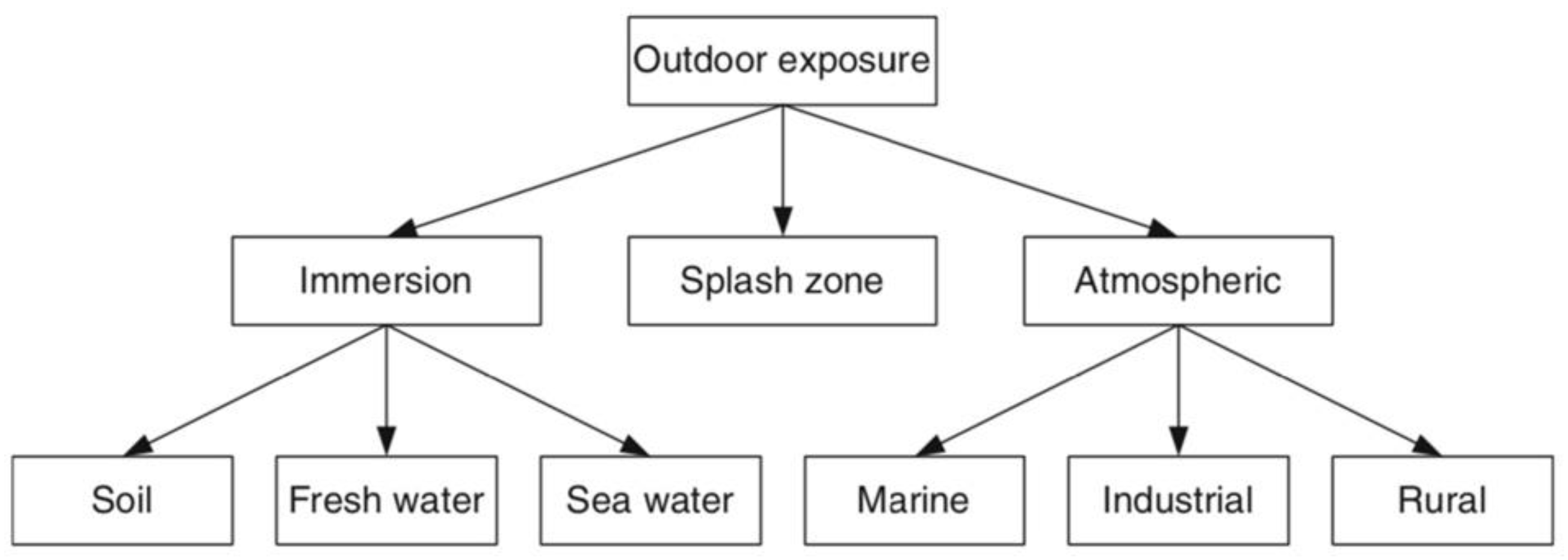
2. Organic Coating Generalities

It is broadly accepted that intact organic coatings inhibit the corrosion of metal structures primarily by acting as a barrier to ions, oxygen and water [11,47,48,49]. Despite the partial disagreement of a minority of authors [39], the community is also acquainted with the fact that the adhesion of the coating to the substrate plays a crucial role in its ability to protect that substrate. In fact, according to [50], diminished adhesion occurs prior to the onset of corrosion. The reason for this is “an electrolyte connection, which is a prerequisite for corrosion onset, cannot be established near or at the intact interface between coating and metallic support before the occurrence of diminished adhesion” [50]. The intimate contact between the atoms of the coating and those of the metal at the interface is promoted by mechanical interlocking (the result of surface preparation) and a certain chemical affinity that enables the formation of chemical bonds. These interfacial bonds should remain intact under dry or saturated (presence of water) environmental conditions, which is known as wet adhesion. Due to the inherent difference between the natures of the coatings and protected substrates, the most common chemical bonds between the two are hydrogen bonds and weaker Van der Waals interactions. As a consequence, there are few polymer–metal bonds that are able to resist hydrolysis over a long period of time [39,50]. Indeed, typical values for metal–coating interactions are in the order of 25 kJ·mol−1 or less, while metal–water interactions have binding energies in the order of 40–65 kJ·mol−1 [51]. Thus, the displacement of the coating by water is energetically encouraged. When this happens, a weak wet adhesion is established and the coating allows an electrolyte solution to be present at the interface that is in contact with the metal substrate, thereby initiating corrosion.
The main mechanism that is responsible for the progressive pooling of water within a coating structure and at the coating–substrate interface is osmotic force. Impurities that remain on a surface prior to coating application or those that are deposited during the curing process, such as dirt, salts and other contaminants, may establish osmotic driving forces and promote water permeation [52]. Additionally, corrosion-inhibiting pigments that are present in some anticorrosion paints/coatings, such as chromates, borates, molybdates, etc., may also promote osmosis and attract water through the coating film due to their water solubility [52]. In cathodically protected systems, the applied electrical charge can also accelerate the permeation of water into the film via a process called electroendosmosis [52].
Physical damage can also negatively affect a coating during its service lifetime. Such defects are almost impossible to prevent and can lead to the rapid failure of coatings. There are many examples of events that can degrade a coating: the collision of vehicles, the careless movement of heavy machinery in the vicinity of the coated surface, coating destruction by a hailstorm or scratches made in a car’s paintwork.
Besides accidental human activity, environmental factors that are encountered by in-service coatings are the main cause of the deterioration of a coating’s barrier effect over time, which can lead to water absorption via the osmotic process and sometimes even the violent and quick destruction of coating systems. Therefore, experts have long studied the effects of different environments on the performance of coatings and have come up with a classification of environments according to their aggressiveness. For example, in ISO 12944, “Coatings and varnishes-corrosion protection of steel structures by protective coating systems” [53], different environments were classified into three types of exposure: immersion, atmospheric and splash zone. Meteorological data are a common input that are needed for the development of models that aim to estimate coating performance and lifetime in-service condition [41,42,43]. In [50], a further subclassification was proposed (see Figure 1).

3. Organic Coating-Embedded Health Monitoring Technologies

3.1. Evolution of the Electrochemical Properties of Coatings

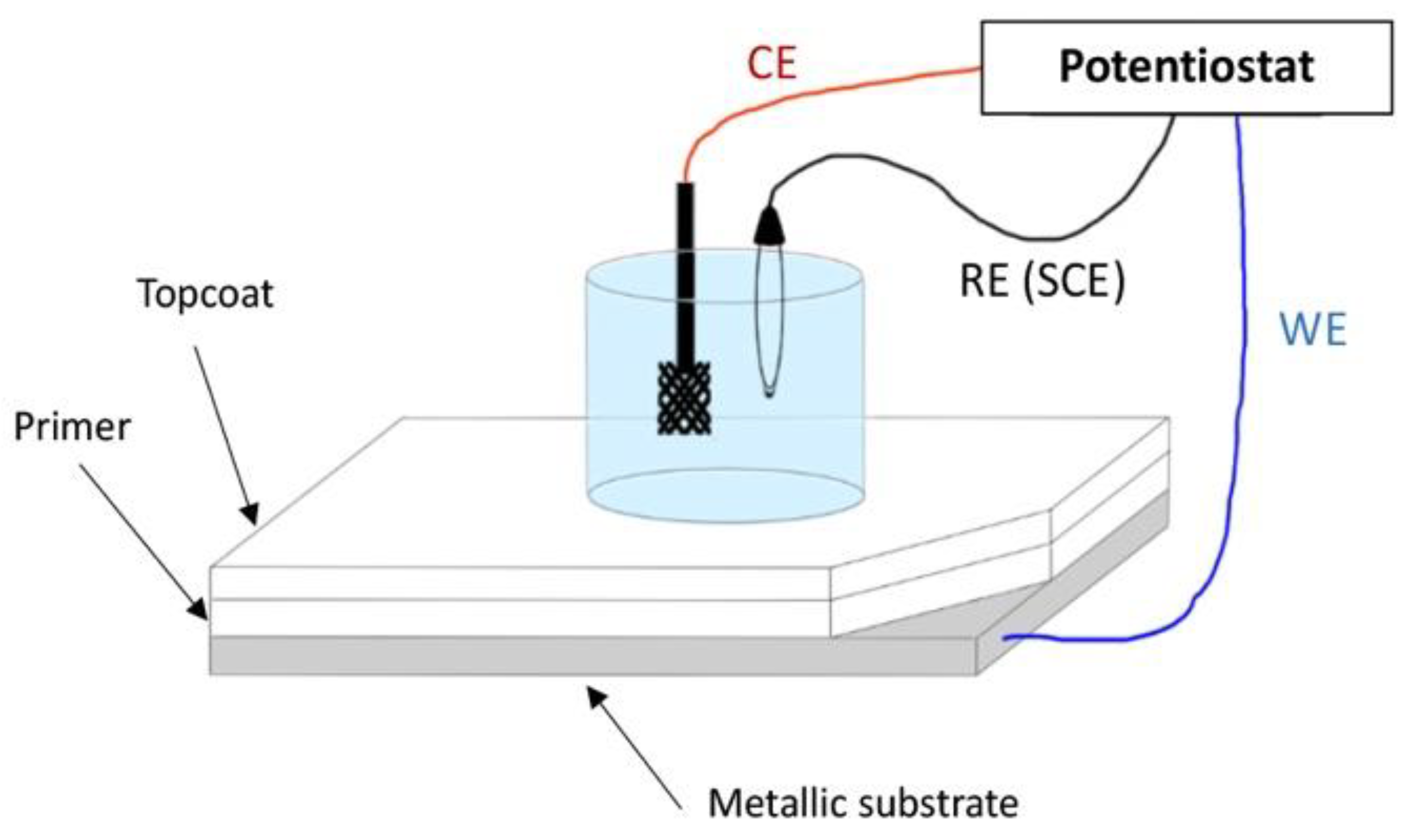
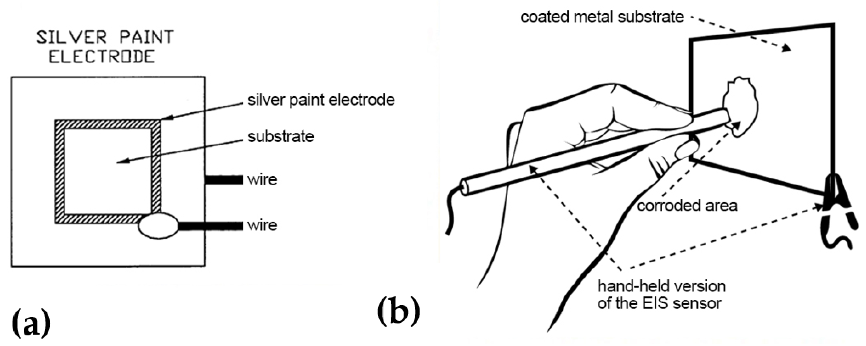
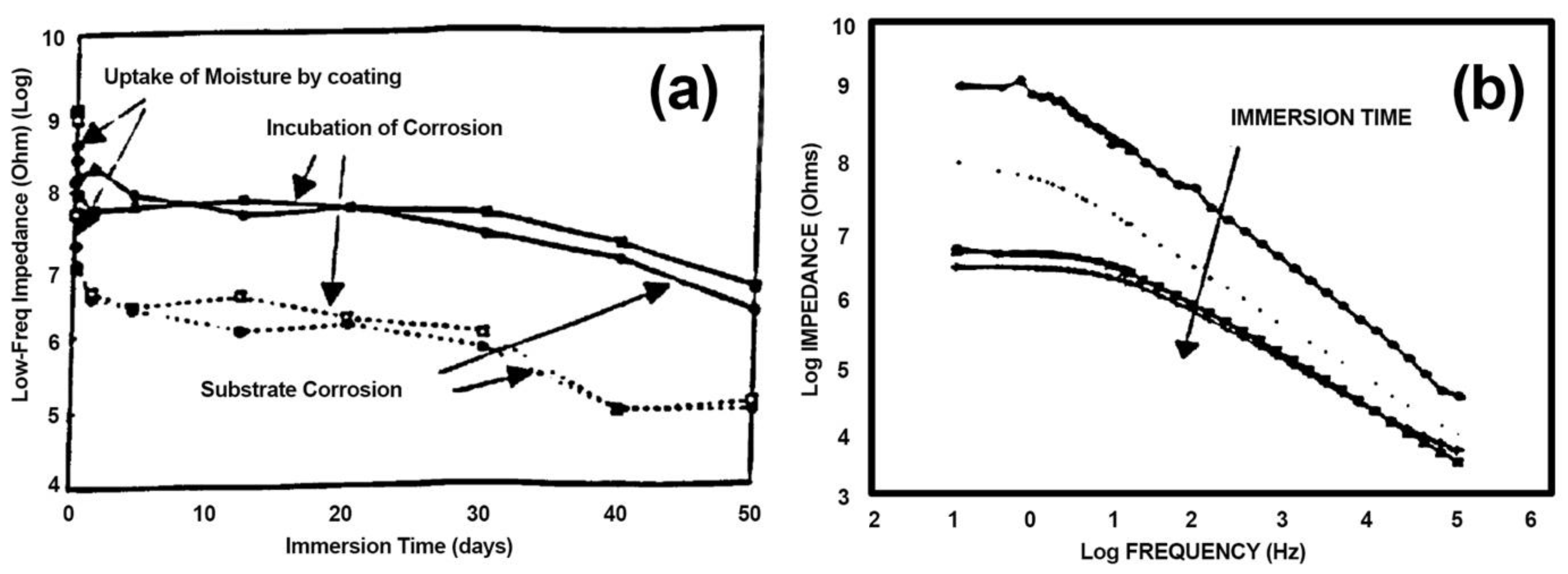
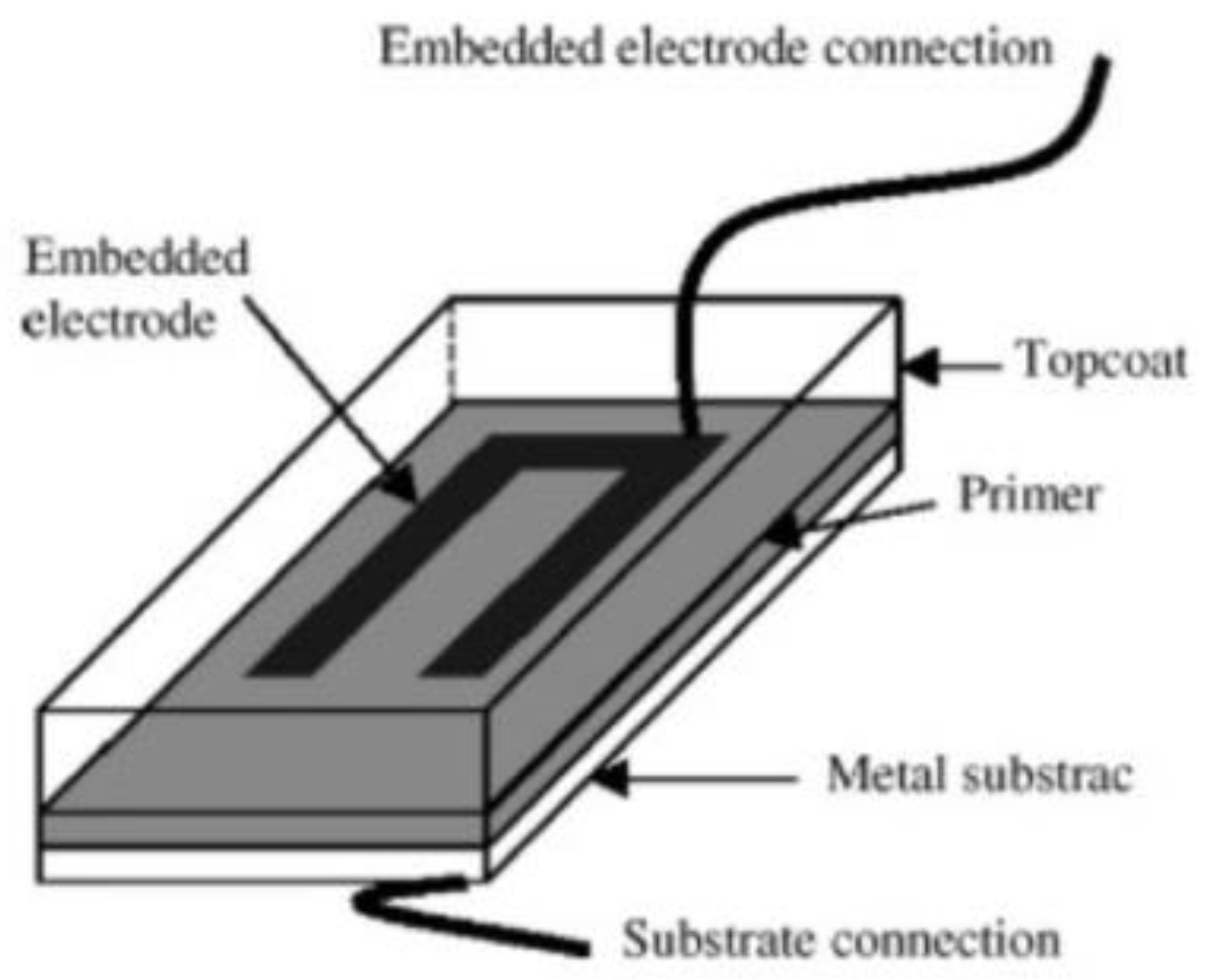
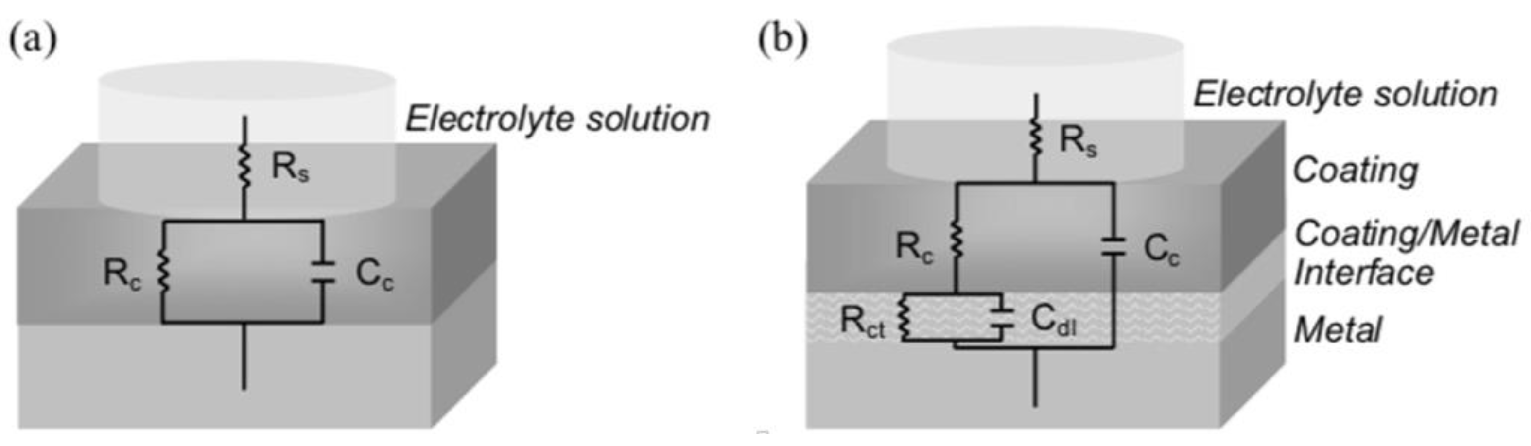
3.1.1. Electrochemical Impedance Spectroscopy (EIS)

Electrochemical impedance spectroscopy (EIS) is a well-known, and historically the most widely used, method for characterising a number of coating properties, such as curing [54], water intake [55,56,57,58,59], adhesion [55,60,61,62] and barrier performance [63,64,65]. EIS studies the response of a coating as it opposes alternate current waves passing through it. In other words, periodic/sinusoidal perturbations are applied across the coating to study its frequency-dependent dielectric properties. The frequency range of the applied AC is very broad, typically ranging from 106 to 102 Hz [66]. It is possible to calculate the current response to a voltage that is applied to the coating through the determination of the impedance (Z) from Ohm’s law: Z = V / I . Impedance is the homologue of resistance, but for an alternating current. EIS data can be plotted in two types of graphics [67,68]: Nyquist plots and Bode plots. The Bode plot representation expresses both impedance magnitude (|Z|) and phase angle (θ) versus frequency.
At low frequencies, i.e., |Z|0.01Hz, the Nyquist or Bode plots provide the total impedance of the coating, since a capacitor acts as an almost infinite impedance at these frequencies. Most of this impedance value is due to the contribution of the coating–metal interphase. It is also at low frequencies that the resistance of the coating to ionic transport can be studied, thereby providing information on barrier or protective properties. For this reason, |Z|0.01Hz can help to assess the health of a coating system. A high value of impedance, such as 109 Ω·cm−2, suggests an almost defect-free continuous barrier with a strong adhesion between the metal and coating. Contact between water or ionic species and the substrate is thus minimised, which prevents the initiation and propagation of corrosion. On the other hand, once the integrity of the coating system is degraded, e.g., due to environmental exposure, the advancement of water through the coating is favoured. A quick decrease in |Z|0.01Hz illustrates an interfacial deterioration process. Below 107 Ω·cm−2, it is considered that the substrate is no longer being protected by the coating system.
By using higher frequencies, such as 2–10 kHz, the capacitance of a coating can be monitored. In order to calculate the capacitance of the coating (Cc), the equation C C = ω | Z |   sin θ 1 is used, where ω is the angular frequency [68,69]. In this frequency range, almost no current flows through the resistance, but all of the current passes through the capacitor whose impedance becomes very low [68]. Moreover, Brasher and Kingsbury [70] showed that the volume percent of water within the coating can be calculated by high-frequency EIS. With the initiation of corrosion and the further deterioration of a coating’s barrier properties, the equivalent models become more complex [54,71,72].
Amirian and Thienyl [72] reviewed all of the fundamentals and the instrumentation and use of EIS for the evaluation of organic coatings.
Figure 2 shows the typical setup that is used for EIS measurements with three electrodes, a reference electrode (RE), a counter electrode (CE), a working electrode (WE) and an electrolyte solution immersion cell. Due to the complexity of the operational setup, EIS was initially not suitable for a use in the field, let alone during the service life of a coating. Therefore, the simplification and miniaturisation of the measuring systems were compulsory, which are now being progressively achieved.
Professor G. Davis has been working on the development of EIS-based coatings and corrosion monitoring sensors for over three decades. Davis et al. [75] developed two in situ sensors, one sensor was permanently attached to the surface and one was hand-held (Figure 3), to monitor the inaccessible areas of a structure and test panels in environmental chambers, such as a salt fog chamber, respectively. It was found that the hand-held sensor is more suitable for conducting spot checks of specimens without the permanent sensor or in areas where permanent sensors are not desired for the reasons of aerodynamics or visual appearance.
In this section, a description of the experimental results, their interpretation and experimental conclusions are presented. As described in Figure 4a, the degradation of different coatings that are exposed to different conditions occurs in three stages [76,77]:
  • The uptake of moisture by the coating,
  • Corrosion incubation time,
  • The corrosion of the substrate.
The differences between the relative time and impedance that occur for the three stages depend on the quality and chemistry of the coating, the metal surface, the surface treatment, and the exposure conditions. Figure 4b summarises a series of EIS impedance spectra that illustrate the typical behaviour of a coated metal. Although the coating initially presents a capacitive behaviour (slope of −1) with very high impedance at low frequencies, the coating progressively degrades and its resistance decreases (as modelled in an equivalent circuit) and its impedance becomes independent from the frequency at low frequencies [76,77].
Some years later, Davis et al. [78] presented the evolution of their electrochemical impedance-based in situ sensor that is capable of detecting coating deterioration and substrate corrosion underneath the coating. It is a sensor that can be used without the need for portable cells, disordered electrolytes, and remote electrodes. Again, two versions of the sensor were presented: a permanent electrode sensor that is suitable for inaccessible areas and a portable hand-held sensor. Both proved to be capable of detecting coating deterioration at very early stages in various accelerated tests and monitoring corrosion in service, allowing condition-based maintenance to be implemented and reducing the probability of failure. The most important breakthrough was that the sensor can also be operated remotely, as it features the option for a wireless connection to a central unit that can display the representative data. The proposed miniaturised and electronic solution was a very remarkable and important step forwards in the development of remote live coating SHM (or coating health monitoring (CHM)) sensors, which notably reduces the size and difficulty of operation of the EIS measuring system (Figure 5).
Its only drawback is that it cannot be totally integrated into the coating system; indeed, it works when it is attached to the outer surface, hence influencing aesthetics and aerodynamics. Their system was later tested to monitor (SHM) anticorrosion coatings in US army ground vehicles [78] (Figure 6).
In these conditions, conventional EIS requires the specimen to be immersed in an electrolyte and the use of a remote counter together with reference electrodes. This setup was adapted to the lab scale for small samples and proper immersion conditions. However, larger specimens require beakers without bottoms that are able to be clamped onto specimens and filled with electrolyte (see Figure 7a). EIS spectra are obtained after both reference electrodes and counters are inserted into the electrolyte. Sometimes, it is necessary to use gels or electrolyte-impregnated sponges instead of a liquid electrolyte. This makes measurements in the field possible, in addition to those performed in the lab, provided that an accessible, flat, smooth, and horizontal surface can be used. This allows users to obtain a local indication of the health of the coating in the area that was wetted by the electrolyte. However, this multistep protocol has been found to be time-consuming. Moreover, too long of an exposure time to the electrolyte can artificially generate damage to the coating during exposition to ambient conditions (Figure 7b). Later, Davis et al. also showed that the area being probed by the in-situ sensors depends on the wetness of the surface. A dry surface provides a localised measurement while a wet surface increases surface conductivity and allows the sensor to detect defects that are away from the sensor electrode. Accordingly, the detection area can be controlled by selectively wetting the surface with water. Under laboratory conditions, Davis’s team were able to detect coating defects up to 15 feet (4.5 m) away. Despite the evident step forwards in EIS-based technology and coating health assessment that has been brought about by Professor Davis’s lifelong work, one main drawback had not been addressed yet: the sensor cannot be fully integrated into an anticorrosion coating system. Instead, it works when it is attached to the outer surface, hence influencing the aesthetic appearance and aerodynamics.
In parallel with Davis’s work, many other routes were being explored with the aim of simplifying and reducing the size and paraphernalia of EIS measuring montages. The scientific community went after a clear goal: coating-embedded EIS technology. Since the early 2000s, researchers have tried to integrate electrodes into coatings to monitor their behaviour. Nevertheless, to be embedded, the electrodes need to be small in size, typically below 1 mm thick. The material for the reference electrodes also must be conductive, stable for chemical and thermal solicitations and resistant to long-term field use and manufacture processing; thus, noble metals are often chosen, such as platinum, gold, silver, and nickel. In [79], Kittel et al. used a nickel grid that was embedded inside a coating in order to separate the contribution of the top layer, which was in contact with the environment, and the inner layer, which was in contact with the substrate, from the total impedance of the system. In [74], Merten et al., with the collaboration of Professor Bierwagen, used micron-scale silver wire for silver/silver chloride-embedded pseudo-reference electrodes. In all cases, a metallic substrate acting as a working electrode was still compulsory. Furthermore, a counter-electrode that was immersed in an electrolyte solution was required to use the external on-surface montage, which consisted of an attached glass cell containing the solution and the CE to perform the measurements. A flat surface was also needed to properly attach the cell.
In [63], Kittel et al. used the same strategy, but with a gold electrode that was embedded in-between the coating layers. What is remarkable in this work is that a measurement setup could include a two-electrode EIS (2E-EIS) without a substrate, such as a platinum mesh that could act as the RE and the CE (denoted as RE/CE). When a metallic substrate was not available, as in conditions in the field, the experiment had to be configured in a way that allowed the current to flow between the CE and WE. Initial attempts with the CE and WE located on both sides of a coating film coupled with electrolyte immersion cells were conducted in the laboratory [80] (Figure 8c). Despite not yet being applicable to a coated substrate in the field, this novel configuration opened the door to in situ embedded-electrode EIS measurements in the field.
In [81,82], Allahar et al. demonstrated that the non-substrate 2E-EIS with an embedded RE/CE and WE in between the primer and top-coat layers can, in fact, be used to obtain information about the metallic substrate. In other words, their results demonstrated the feasibility of monitoring the coated metallic substrate without the same substrate itself being an electrode. It was hypothesised and demonstrated that the current between the coating-embedded electrodes also flows through the metallic substrate despite it not being an electrode or being in contact with the electrodes (Figure 9).
The goal of embedded EIS coating sensing was thus achieved and paved the way for embedded coating health monitoring sensors. Some other examples can be found in the literature [48,55,83]; however, most published articles concerning embedded electrodes for the electrochemical monitoring of coatings have used the similar but different electrochemical technique of electrochemical noise measurement (ENM). Let us try to understand why.

3.1.2. Electrochemical Noise Measurements (ENM)

ENM monitors the small potential and current fluctuations that occur naturally in electrochemical cells to evaluate corrosion processes and coating states, with the latter being the focus of this work. Several advantages and disadvantages are often noted when ENM is compared to EIS. First of all, ENM does not require a sinusoidal perturbation; therefore, it is considered less intrusive than EIS [73]. In the same work, Bierwagen et al. stated: “the primary reason for the failure of EIS methods in cyclic exposure conditions…” (similar to those encountered by coatings in-service) “…is that in the potentiostatic mode, all measurements are made about Ecorr of the system under investigation, and if Ecorr is time dependent at a rate that exceeds the lowest frequency of the EIS measurements, the system is non-stationary and applying EIS techniques give errors” [73]. Therefore, when the corrosion potential of a system is not stable, the measurements of EIS at low frequency are often erroneous. Thus, ENM measurements have proved to be more accurate and quicker for gathering data than EIS. Nevertheless, ENM has drawbacks that can lead to a greater variance [84] and the results are based on a more complex theoretical foundation than those of EIS [73]. Iverson [85] first found a correlation between electrode potential fluctuations and corrosion processes, whereas Eden and Skerry [86] first applied the technique to coated metals.
The most common representation of the fluctuations, also named noise, in voltage (V) and current (I) that are recorded in ENM is noise resistance, Rn. It is calculated as the ratio of the standard deviation of the voltage noise to the standard deviation of the current noise [87,88]: Rn = σV (t)/σI (t). Experimentally, Rn is equivalent to the low-frequency impedance, |Z|0.01Hz, that is obtained from EIS [89]. As in EIS, a decrease in Rn is indicative of increased coating degradation due to the advancement of water, ions, and other destructive species into the coating system.
Other interesting papers on ENM theory fundamentals, application and results interpretation can be found in the following references: [69,90,91].
The traditional experimental setup for organic coating noise measurement is shown in Figure 10. A salt bridge enables the current to flow between the two samples. The CE lead is connected to one substrate and the WE lead is connected to the other. A laboratory RE is needed in one of the electrolyte cells. The use of a zero-resistance ammeter (ZRA) allows the user to keep the potential difference at zero during measurement. The early ENM montage was satisfactory for laboratory use but was clearly not suitable for in-service monitoring or quality control.
Mabbutt and Mills [92] soon realised the need for montage simplification and introduced an alternative experimental setup, which eliminated the need for two isolated specimens and the salt bridge. Their double reference electrode setup reduces preparation time and set the basis for embedded electrode techniques. This device is composed of a single substrate/sample with two electrolyte immersion cells and a support that is connected to the RE lead, whereas the reference electrodes replace the previous WE lead (Figure 11a). Indeed, the Mabbutt and Mills setup is often referred to as a “reverse configuration”, as all of the electrical components are reversed. Subsequently, reverse ENM experiments [90,93] can proceed without a connection to the substrate, in which three lab electrodes are electrically isolated by the electrolyte immersion cells (Figure 11b). This set the basis for the in-situ application of ENM, in which a connection to the substrate is not feasible (no connection to the substrate, NOCS).
In [94], Mills et al. used single substrates in operation with an electrolyte-soaked filter paper instead of the electrolyte immersion cell. A copper foil that was used as pseudo reference electrode was placed on the filter paper and taped to hold it steady (Figure 12). Suitable results from the ENM measurements were obtained by connecting this to the electrode.
ENM measurement using the reverse configuration was proceeded by replacing the lab reference electrodes with an embedded Pt mesh. ENM was also successfully operated by Wang et al. [73], who placed Pt wire electrodes inside the coating to characterise the organic coatings. This in situ configuration can be used for continuous measurement if the humidity does not compromise the conductivity requirements. Su et al. [95] studied the AC–DC–AC-accelerated weathering of aircraft and industrial coatings using ENM with embedded Pt foil leaf electrodes (Figure 13). Subsequently, the materials were also aged by thermal cycling [96] and prohesion [69]. They also compared the EIS measurements to reverse configuration ENM results.
In [69], a novel electrochemical noise (EN) setup was used with embedded electrodes (EEs), which was found to be suitable for the in situ testing of the integrity of organic coatings when submitted to a marine alternating hydrostatic pressure (AHP) environment (Figure 14). The analysis of the EN results from the EE configuration were compared to those obtained from a conventional EIS configuration. Moreover, the corrosion behaviour of the substrate below the coating was analysed to determine the performance of the protective coating. The results confirmed that the in-situ EE configuration under AHP is a valid and reliable approach.
Another versatile and quick technique that can be used to determine whether there are defects in coatings and the level of protection that is available is electrochemical noise measurement [69,88]. However, it has been noticed that with this device, the data analysis is more complicated in passive and inhibited systems and that the collection of data and the choice of methods for analysis are determinant in the effectiveness of the technique [84,90]. Additionally, as for EIS, ENM is sensitive to external electromagnetic fields and needs quite complex instrumentation to overcome these perturbations.

3.1.3. Potentiodynamic Polarisation Measurement (PDP)

This kind of measurement belongs to one of the most commonly used DC electrochemical methods for corrosion measurement. The polarisation curve can be used to determine the corrosion potential and the corrosion rate of the metal under the given conditions (Tafel slope). The advantage of this method is reflected in the possibility of localised corrosion detection, the easy and quick determination of the corrosion rate and the efficiency of the corrosion protection. More details can be found in the book chapters of Vastag et al. [97] and Atta Ogwu et al. [98].

3.2. Evolution of the Internal Stress–Strain State of Coatings

“A direct measurement of internal stresses would be necessary to go deeper in the understanding of the coating degradation modes” [37]. In their article, Perrin et al. studied the influence of the alternation frequency of different weathering conditions on the mechanisms and rate of coating degradation. The studied coating was a three-layer system composed of an epoxydic primer and basecoat and an alkyd top-coat on steel substrates. It was found that the frequency of change between different conditions, such as immersion/emersion or hot/cold, had a greater impact on the coating degradation than the duration of each different step. In other words, degradation was greater and faster when samples underwent different conditions successively compared to when they were kept in a single type of environment, even when they were kept there for a longer cumulative period. It was hypothesised that this could be related to the impact of alternating between different environments on the mechanical properties of the coating’s polymeric binder.
Indeed, right after the coating is applied and cured, the polymeric network is at its maximum internal stress state due to shrinkage being prevented by surface interlocking and bonding forces. With exposure to the environment and time, the internal stresses of the polymeric network progressively relax. In the long term, surface cracks can develop because of such relaxations. This, in turn, further facilitates the ingress of water molecules into the coating, which induces swelling in the polymeric network and changes the coating’s internal stress–strain state because of plasticisation. When corrosion subsequently develops at the coating–substrate interface and corrosion products accumulate underneath the coating, strains result in the vicinity of the cracks. One common trend can be observed in all these situations: each stage of the coating’s lifetime has an impact on the physical and mechanical condition of the coating and its polymeric network. Therefore, it seems reasonable to assume that when the coating’s internal mechanical state and its evolution over time could be monitored, it may be possible to correlate internal stress–strain changes with the events that were responsible for that change; thus, it may be possible to follow the coating’s condition in real time. From these findings, a question can be raised: is it possible to measure changes in the internal polymer stress–strain state of a coating accurately enough to detect the changes that were induced by each of those events?
Commonly, strain is measured by gluing metallic strain gauges onto a substrate. This, however, has inherent disadvantages in terms of forced coupling between the surface strain of the bent substrate and the glued strain gauge sensors [91]. The fact that, in general, the glue and the strain gauge substrate have different moduli of elasticity affects the maximum achievable sensitivity [91]. Moreover, since the sensors are attached to the surface, their monitoring range is practically limited to the coating’s surface.
However, several different technologies that approach the problem with various original technical means have been proposed by the scientific community and are presented below.

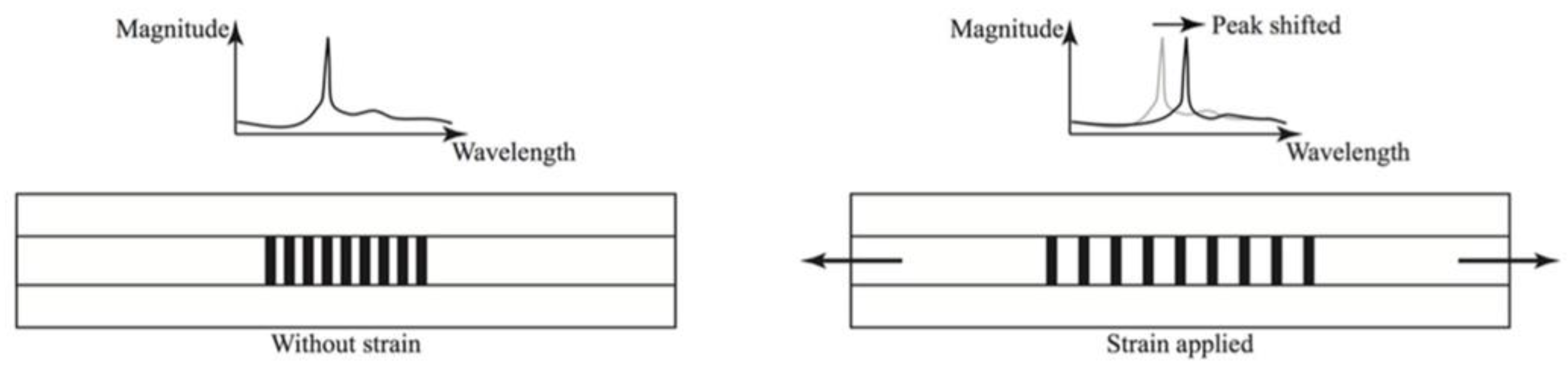
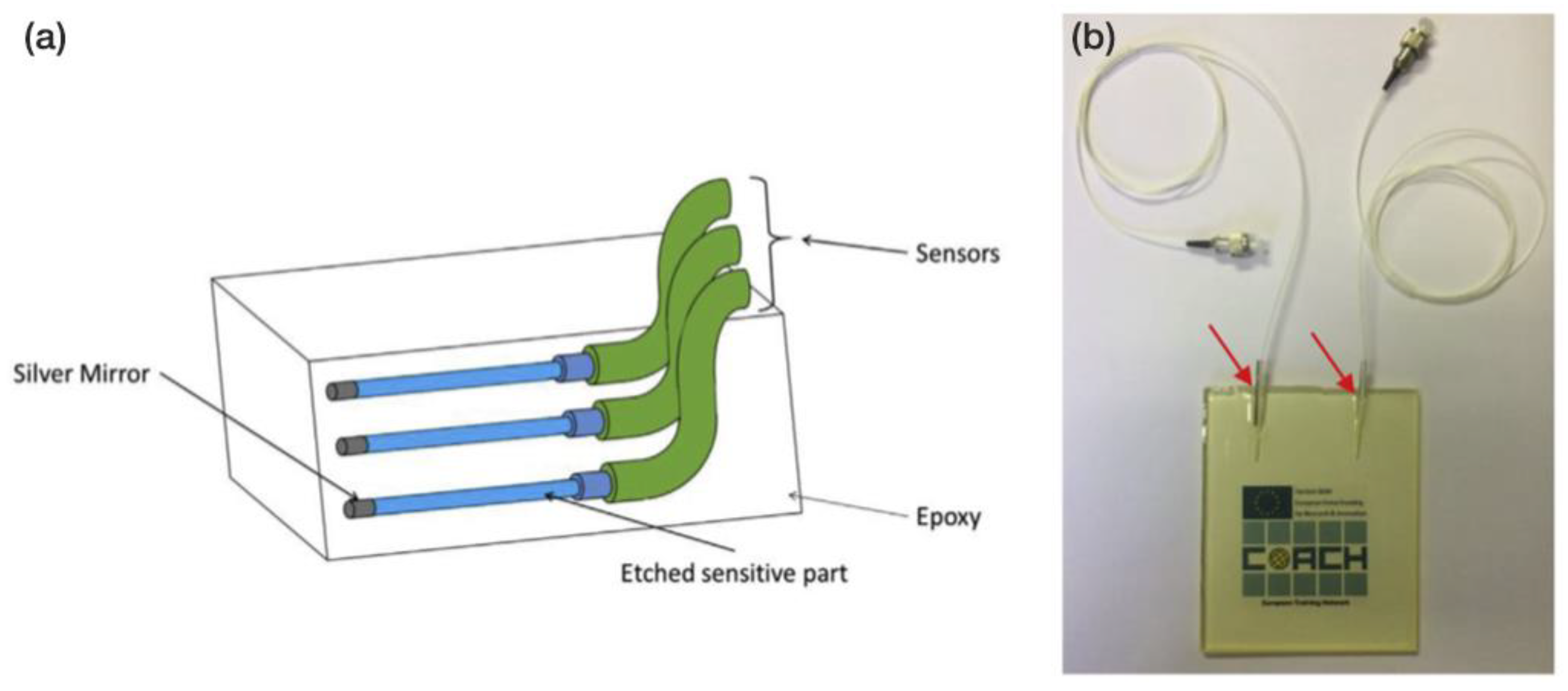
3.2.1. Optical Fibres–Fibre Bragg Gratings

A fibre Bragg grating (FBG) is a short portion of optical fibre, in which a certain pattern that induces periodic changes in the refractive index of light has been created. This acts as an optical filter that reflects some wavelengths and transmits others [99]. Reflected and transmitted wavelengths depend on the spacing of the patterning. When such an optical fibre is embedded into a coating, typical coating-related phenomena, such as swelling due to water absorption, deformation due to osmotic blistering or delamination, can alter the distance of the Bragg grating patterning, which results in changes to the reflected/transmitted wavelengths. In other words, changes in the coating strain result in a shift in the Bragg grating wavelengths (Figure 15).
Ramezani-Dana et al. [101] presented a technique based on fibre Bragg grating (FBG) that is capable of accurately measuring mechanical strains inside polymeric composite materials. The technology is used to monitor the ingress of water into the laminate composites by tracking the water-induced swelling of such materials and to estimate their moisture expansion coefficients. The FBG sensors are embedded in between the composite layers. By inscribing several FBGs with different grating periods within the same optical fibre, an array of gratings was manufactured, which allows different positions within the structure to be monitored with a single sensor line.
Similarly, Marro Bellot et al. [29] used low-cost optical fibre sensors (OFS) that were embedded in epoxy matrices to monitor water diffusion into the matrices (Figure 16a,b).
To fabricate the single-ended evanescent wave OFS that was used in that study, standard glass optical fibres were chemically etched to expose the core, within which the light was confined, to the surrounding environment. Initially, 125 µm diameter optical fibre wires were reduced to a 50 µm diameter by etching their coating (Figure 17a). The etched wires were then embedded into glass fibre-reinforced epoxy matrices (Figure 17b) and the samples were immersed in simulated sea water at 80 °C. The sensors were interrogated using a low-cost benchtop spectrometer that worked in the near-infrared spectrum. Optical fibre-based technologies for SHM are experiencing a strong expansion due to their advantages over other kinds of technologies. As they are based on optical properties, they are not susceptible to electromagnetic fields, they show a high sensitivity of measurement and they do not conduct electricity because they are made of inorganic non-metallic materials, all of which only allows the propagation of light along the fibre. OFSs have been successfully tested in extremely hazardous environments, such as high and low temperatures and pressures, very corrosive media, radioactive zones, etc. With a single OFS, it is possible to perform measurements at different distant points (remote sensing).

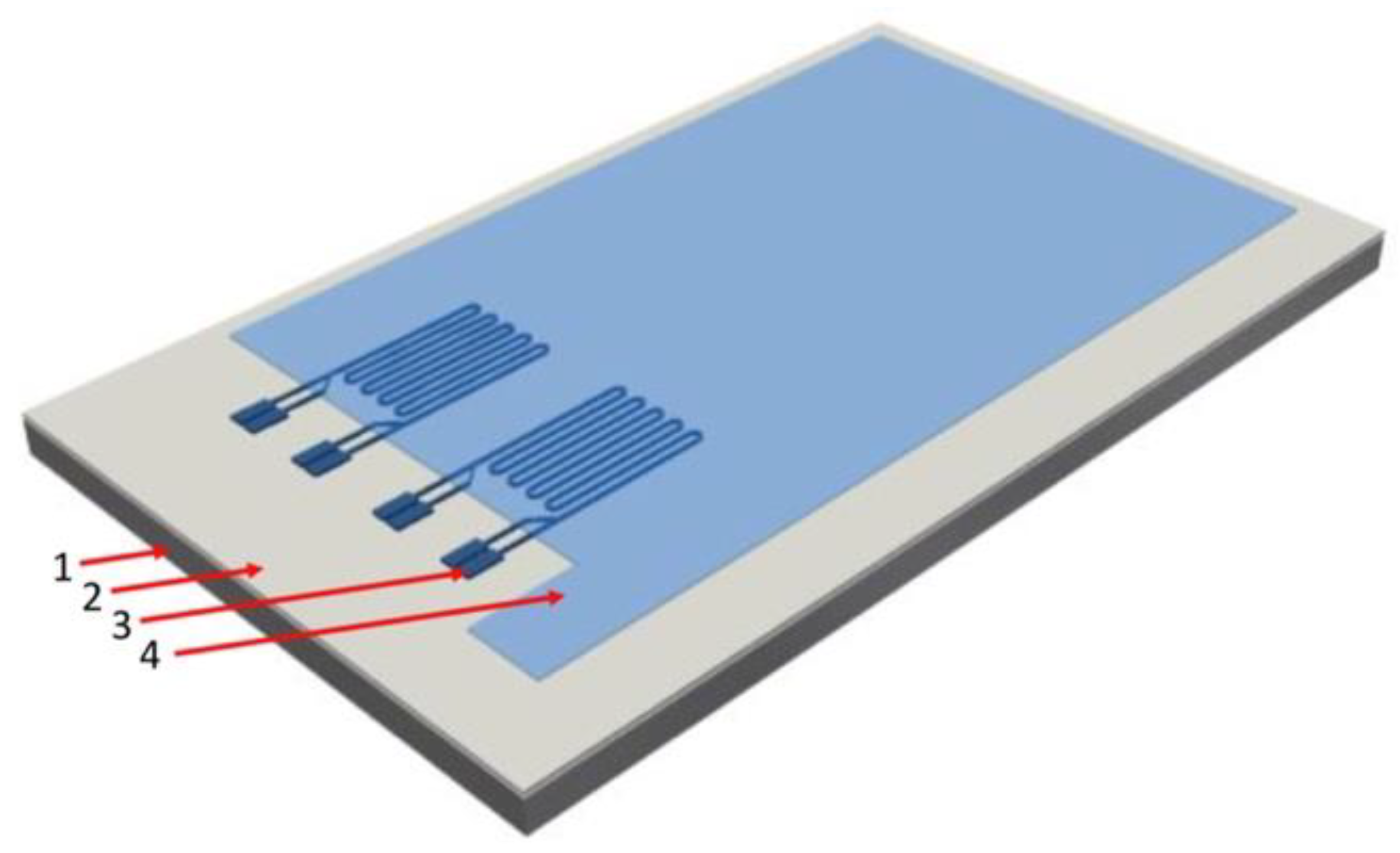
3.2.2. Embedded Piezoresistive-Based Strain Gauges

In their work, Enser et al. [102,103,104,105] seemed to adapt a promising existing technology [106,107] that has recently been applied to structural health monitoring (SHM) for use in organic coatings. Enser et al. used the piezoresistive properties of certain types of nanocomposites to fabricate an internal strain gauge by printing the sensing part inside a coating, sandwiched in between the basecoat and top-coat layers (Figure 18). By doing so, the main drawbacks that are associated with surface-attached gauges can be circumvented. There is no longer a need for a glue and there is a very reduced geometrical distance to the substrate, which thus improves the force coupling between the substrate and the sensor and achieves a higher gauge factor. Furthermore, the strain gauges are easily and inexpensively made by screen-printing electrically conductive ink-based sensing electrodes onto precoated steel substrates prior to the addition of a stabilising top layer, which closes the coating “sandwich”. The authors compared two different types of inks: silver-based and carbon-based. The silver-based ink showed a gauge factor that was similar to that of a common surface-glued gauge and a good linearity with temperature, while the carbon-based ink showed a gauge factor that was almost three times higher than that of a common gauge but its temperature coefficient was only approximately linear with temperature in a very small temperature range [105]. In any case, a temperature shift correction has to be applied to this kind of strain sensor, as temperature affects the piezoresistive operating principle. Enser et al. used their mechanical sensors to study the bending of coated steel cantilevers and to fabricate integrated capacitive touch sensors as well [108].
However, can this kind of coating-integrated strain sensor be used to monitor the physical properties of a coating in the long term? Instead of using them to detect induced bending deformations at a given punctual time, can this piezoresistive-based technology track the internal stress–strain evolution that occurs through the lifetime of a coating as it ages? In other words, can they be used to sense, for example, coating swelling that was caused by water absorption or strains that were induced by the formation of blisters in the coating? If this were possible, advantages over the previously reviewed electrochemical-based techniques or optical fibres could be numerous, for instance: the complete integration of the technology that is embedded inside anticorrosion coating systems without any aesthetic or aerodynamic impact; the thinner embedded strain gauges comparison to OFSs may be less invasive; simple and direct data interpretation; and probably an easier and less expensive fabrication process. On the contrary, if these hypotheses were ever confirmed, a thorough study of the coating to be monitored would have to be conducted in a lab in order to understand its weathering response and degradation mechanisms. Moreover, despite relatively similar trends, degradation modes are unique for each coating type, which makes it imperative to study each coating system beforehand. Finally, an offset correction would also be necessary, as temperature greatly influences the sensors [105].

3.3. Other Technologies

Trinchi et al. [28] used magnetic nanoparticles that were embedded into anticorrosion primer coatings to sense the depletion of corrosion inhibitor molecules within the coating. In corrosive environments, such nanoparticles are transformed into chemical species with different magnetic and structural properties. By monitoring changes in their magnetic state, it is possible to make correlations between the magnetic state of the particles and the number of remaining inhibitor molecules in the coating, thereby making a novel approach using both non-destructive and non-contact sensors possible. It has also been suggested that their interactions with alternating magnetic fields can be used to monitor the magnetic particles in coatings in a non-destructive and non-contact way.
For anticorrosion coating detachment detection, Zarifi et al. [109,110] proposed the use of radio frequency identification (RFID). This technology uses passive sensing tags on pipes that are powered and connected by a wireless external reader. Any damage in the polymer coating results in a change in the distance between the coating and the metal pipe and therefore, affects the interdigitated capacitor on the tag. The capacity variation is communicated to a reader coil and its effect is reflected in the return loss parameter, thereby making it possible to detect when air or water has diffused under the coating. With the measurement of the sensors being local, the coverage of a large surface requires several RFID tags in a wide range of frequencies to avoid interference. Wireless communication makes it possible to integrate such sensors into bonded joints, for example, but they could be intrusive, depending on their size.
In their work, Wilson and Muscat [111] presented a technology that is able to “detect the presence of corrosion due to sea water environment and determine when a paint or sealant has been unable to protect the underlying metal. The sensor is thus expected to alarm when the protective is compromised.” To do so, they used insulated thin aluminium alloy (AA) 2024 wires as corrosion sensors. Their sensor was made of a thin conductive wire of 25–100 μm diameter wrapped into an insulating coating of 2–3 μm. This insulating coating was partly removed by ultraviolet laser ablation on small sections to expose the metallic wire to its environment. The wire was then laid on the surface of a conducting structure and coated with paint or sealant. The conductance that was measured between the wire and the conducting surface on which it was placed was initially very low, whereas the end-to-end conductance was high. However, the presence of ions in the vicinity of the exposed portion of wire and the conducting surface could also increase the conductance between the wire and the surface.
This configuration conveniently only requires a few simple DC electrical measurements to detect the presence of corrosion through changes in the resistance between the sensing wire and the substrate. Another advantage is that the long-term stability of the sensor is affected in the same way as the paint in which it is embedded. The wire can also be fabricated from the same material as the structure that is being monitored, so it is likely to corrode in a similar manner. For these sensors, the wire is thin compared to the typical thickness of the paint layer on ships, which can go up to 1 mm, thus making them suitable to be fully embedded in anticorrosion systems. As the failure of the paint is measured directly, it is not necessary to model the response of the coating to its environment. Thus, when the wire is corroded, this means that corrosion is reaching the metal surface. In an enclosed area, it is relatively simple to run a few electrical wires to perform DC measurements externally. A summary of all of the reviewed embedding techniques for the monitoring of organic coatings is presented in Table 1.

4. Connectivity and Sensor Networks: Towards Neural Systems and Industry 4.0

Up to this point, a wide range of technologies has been reviewed, which have different original approaches to the problem of coating health assessment. With a few exceptions, all of the technologies compiled herein are in the early stages of development. Typically, individual sensors in the prototype phase are tested on laboratory-scale samples and fixtures that recreate in-service conditions. However, corrosion prevention technologies are most often applied to very large infrastructures, such as buildings, bridges, aircrafts, ships, pipelines, tanks, etc., for which a single sensor is evidently not sufficient to obtain a representative image of the overall health state.
The arrival of 5G wireless technology is set to ignite the fourth industrial revolution [112,113,114,115]. In this upcoming so-called Industry 4.0 context, the Internet of Things (IoT) will experience considerable growth and will certainly become a key strategic sector in tomorrow’s society. In industry, the IoT will eventually allow manufacturing systems “to communicate, analyse and use collected information to drive further intelligent actions” [113]. Heading in that direction, many of the reviewed technologies will be integrated into connected networks that are able to centrally process the data collected by multiple remote nodes located at strategic points along the infrastructure. In the literature, these are known as neural systems, as they mimic the human nervous system [116,117]. To achieve this, two major challenges need to be addressed: sensor connectivity and power sources. The technologies reviewed above are intended to work when embedded into anticorrosion coatings, which means that wired networks are not the best solution for either the connectivity or power source of the sensors. In addition, the application sensing technologies in non-accessible zones do not permit the use of finite batteries either, as it would be impossible to replace the batteries once they were fully discharged. Therefore, wireless and autonomous systems that are capable of self-generating power are the alternative.
The need to acquire data from a variety of widely distributed sensor nodes has propelled the creation of predesigned platforms and systems that are thought to speed up the development of connected sensor networks. With this in mind, with their conductive wire measuring technology, Wilson and Muscat performed their measurements using a low-power networked sensor interface that was developed by the Australian Defence Science and Technology Organisation (DSTO) and was specially designed for the rapid development of monitoring networks [118,119]. The system was designed to easily enable new sensor accommodation, thereby minimising the engineering effort that is required to develop new hardware and software variants. The core predesigned module includes network communications, microprocessor control and digital input/output. In addition, the software is also of a modular design that consists of a set of core operating routines and a set of routines for controlling sensor operations that can be downloaded or upgraded in the field. Special attention was paid to the need for small size, low weight, low power, and versatility of operation. The unit is 40 mm wide, 16 mm high and typically 55–65 mm long, depending on the complexity of the sensor interface. The development philosophy was to develop a modular system with common hardware and software to manage these communications and the configuration of any sensor interface.
A very similar approach was reported by Demo et al. [120], who developed a system that is capable of monitoring, recording and analysing data from wireless environmental and corrosivity sensors for aircraft health management. The Luna system consists of multiple wireless sensor nodes and a centralised sensor hub that was modelled on the IEEE-1451 family of standards for sensor networks. Two key components were identified to develop this kind of network: TIMs and NCAPs. The base board can manage the system power consumption by activating and deactivating components on an as-needed basis, while also allowing external stimuli to trigger wakeup events as required. Additionally, the design relied on ultra-low power components and energy conservation algorithms. This low-power device for corrosion and health monitoring is compatible with energy harvesting techniques, thereby giving rise to a self-supplied sensor network.
In [121], a thorough review of all of the possible power sources that use the human body to power wearable and implantable electronics was presented. The same approach to the problem of powering discrete sensors could be applied in the case of coating-embedded anticorrosion sensors, i.e., take advantage of the sensors’ surroundings to generate electric power, thus achieving full autonomy for each distributed sensor node. Each node would need to consist of a sensing unit, an attached electronic circuit for data acquisition and transmission to a central hub and a power generator. Numerous examples of small integrated power generators can be found in the literature due to the recent boom in the power generation and energy harvesting sectors since the irruption of nanotechnology. The most common examples that are related to this work use temperature [122,123,124] or concentration gradients [125], while others take advantage of friction [126] or vibrations [127,128,129] to generate electrical currents.
To put forward some figures of merit, a thermogenerator that consists of a compressible elastic aerogel exhibited an optimum output power of 1967 nW with 10 legs at 50% strain and ΔT = 50 K [124]. The power output could be tuned by the function of the number of legs. In another case, a generator prototype that was 240 mm3 in size took advantage of external vibrations and showed a power output of 0.53 mW at a vibration frequency of 322 Hz [118].

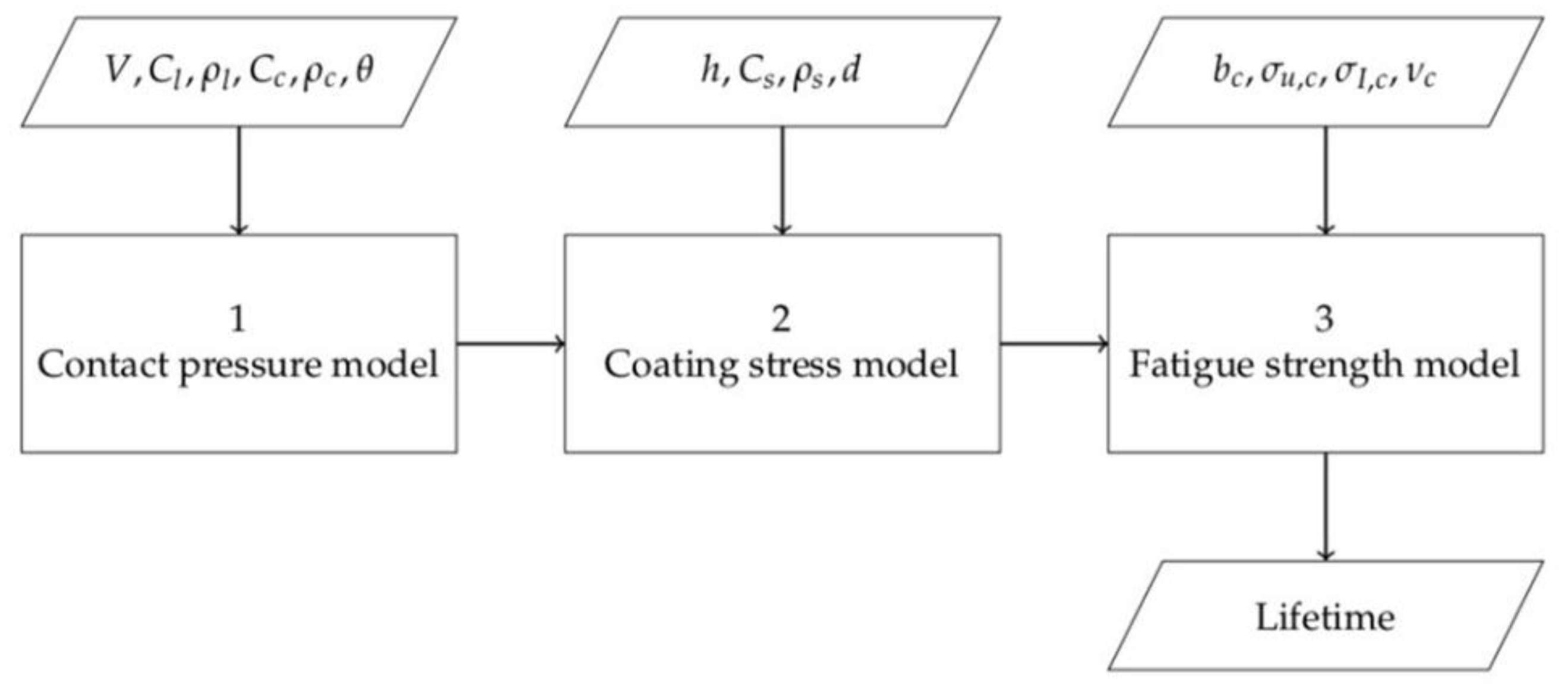
5. Modelling of Coating Behaviour

The newly developed technologies that were reviewed in this work may potentially be used to obtain input data to feed existing models and enhance their accuracy or to develop new ones. Therefore, it was considered important to briefly summarise some of the existing models that aim to assess the condition of coatings and predict their lifespan.
In [130], conceptual and mathematical models for the formation of blistering on organic coated steel were presented.
Similarly, the deterioration process of an organic coating layer that protects steel from corrosion was modelled by three different numerical models and compared in [131]. It was concluded that the deterioration of the organic coating was nonlinear over the course of time.
The modelling of the behaviour of coatings and the evolution of their electrochemical properties through equivalent electronic circuits is omnipresent and one of the main interests of the EIS technique [132]. Various electrical components, such as resistors and capacitors, are applied to model the resistive and capacitive nature of the coating system. A Randle’s circuit is shown in Figure 19a. This simple, three-component circuit is used as a first approximation for most coating systems. As coating degradation progresses and corrosion initiates at the metal–coating interface, the complexity of the model increases, as shown in Figure 19b. An example of the latter can be found in [133].
One of the most widely recognised models for coating lifespan estimation is the Springer model [135,136], which has long been used for the prediction of protective coating lifespans for several types of blades, such as steam turbine blades, aircraft propellers and wind turbine blades. In all of the latter cases, the blades undergo mechanical erosion due to the impact of rain droplets and dust particles, among others, at very high speeds. In [134], a review of the model and its sensitivity for lifespan prediction for windmill coating systems was presented. The model was split into three parts (see Figure 20): the first part determines the pressure that the liquid droplet exerts on the coating system; the second part determines the stress in the system based on the contact pressure; and the third part uses the computed stress to calculate the coating system’s lifespan based on its fatigue properties. The three models are solved consecutively to obtain an estimation of the coating’s lifespan.
Due to the age of the model, which was developed in the 1970s, many simplifications were assumed in each of the three parts that were reviewed in [134].

6. Conclusions

The monitoring of a coating’s electrochemical properties has historically been the most widely used method to assess coating performance and under-coating corrosion. Since the beginning of the 21st century, the evolution and miniaturisation of the apparatus that are needed to perform electrochemical measurements have been truly remarkable to the point that, nowadays, numerous coating-embedded solutions exist. On the other hand, inherent limitations, such as the impact of electromagnetic fields, the difficulty of the technique’s theoretical basis and the equally complex data gathering and interpretation, have made the scientific community consider other approaches to the problem of the monitoring of organic coating. The tracking of the evolution of physical properties with coating aging has proven to be a viable alternative for coating health assessment that is easier and more direct overall. The use of embedded optic fibres is among the most used techniques that can do so. In turn, their fragility, and the fact that they are more invasive than other techniques due to their dimensions mean that OFs are not yet the perfect solution to the problem. Emerging alternative solutions, such as embedded piezo-resistive gauges, may become the simplest and most widespread solution to the problem in the coming years. Independently from the assessment technique and bearing in mind that they are not exclusive, but instead may be complementary, the direction of scientific development is, without any doubt, heading towards the integration of gauges into neural sensing networks. The solutions that are the simplest, easiest to integrate and least power-consuming will most probably overtake the rest.

Author Contributions

Conceptualisation, M.C. and J.-F.F.; methodology, X.F.-C., M.C. and J.-F.F.; validation, X.F.-C., A.-M.G., J.-F.F., M.C. and D.-D.N.; formal analysis, X.F.-C., M.C. and J.-F.F.; investigation, X.F.-C., M.C. and J.-F.F.; resources A.-M.G. and J.-F.F.; writing—original draft preparation, X.F.-C.; writing—review and editing, X.F.-C., M.C. and J.-F.F.; visualisation, X.F.-C., M.C. and J.-F.F.; supervision, M.C.; project administration, A.-M.G., D.-D.N. and J.-F.F.; funding acquisition, A.-M.G. and J.-F.F. All authors have read and agreed to the published version of the manuscript.

Funding

This research was funded by the Naval Group and CIFRE (grant number 2019-0141).

Institutional Review Board Statement

Not applicable.

Informed Consent Statement

Not applicable.

Data Availability Statement

Not applicable.

Acknowledgments

The authors would like to thank Hervé Bellégou from the University of South Brittany (UBS) and Simon Frappart from the Naval Group for their contribution to this work.

Conflicts of Interest

The authors declare no conflict of interest.

References

  1. Kendig, M.; Mills, D.J. An historical perspective on the corrosion protection by paints. Prog. Org. Coat. 2017, 102, 53–59. [Google Scholar] [CrossRef] [Green Version]
  2. Fayomi, O.S.I.; Akande, I.G.; Odigie, S. Economic impact of corrosion in oil sectors and prevention: An overview. J. Phys. Conf. Ser. 2019, 1378, 022037. [Google Scholar] [CrossRef]
  3. Soliman, M.; Frangopol, D.M. Life-Cycle Cost Evaluation of Conventional and Corrosion-Resistant Steel for Bridges. J. Bridge Eng. 2015, 20, 06014005. [Google Scholar] [CrossRef] [Green Version]
  4. Shekari, E.; Khan, F.; Ahmed, S. Economic risk analysis of pitting corrosion in process facilities. Int. J. Press. Vessels Pip. 2017, 157, 51–62. [Google Scholar] [CrossRef]
  5. Ulaeto, S.B.; Rajan, R.; Pancrecious, J.K.; Rajan, T.P.D.; Pai, B.C. Developments in smart anticorrosive coatings with multifunctional characteristics. Prog. Org. Coat. 2017, 111, 294–314. [Google Scholar] [CrossRef]
  6. Feng, W.; Patel, S.H.; Young, M.-Y.; Zunino, J.L.; Xanthos, M. Smart Polymeric Coatings—Recent Advances. Adv. Polym. Technol. 2012, 32, 474–485. [Google Scholar] [CrossRef]
  7. Li, W.; Hintze, P.; Calle, L.M.; Buhrow, J.; Curran, J.; Muehlberg, A.J.; Gelling, V.J.; Webster, D.C.; Croll, S.G.; Contu, F.; et al. Smart coating for corrosion indication and prevention: Recent progress. In Proceedings of the CORROSION 2009, Atlanta, Georgia, 22–26 March 2009. [Google Scholar]
  8. Al-Saffar, Y.; Aldraihem, O.; Baz, A. Smart paint sensor for monitoring structural vibrations. Smart Mater. Struct. 2012, 21, 045004. [Google Scholar] [CrossRef]
  9. Egusa, S.; Iwasawa, N. Piezoelectric paints as one approach to smart structural materials with health-monitoring capabilities. Smart Mater. Struct. 1998, 7, 438–445. [Google Scholar] [CrossRef]
  10. Gray, H.N.; Jorgensen, B.; McClaugherty, D.L.; Kippenberger, A. Smart polymeric coatings for surface decontamination. Ind. Eng. Chem. Res. 2001, 40, 3540–3546. [Google Scholar] [CrossRef]
  11. Zheludkevich, M.L.; Tedim, J.; Ferreira, M.G.S. “Smart” coatings for active corrosion protection based on multi-functional micro and nanocontainers. Electrochim. Acta 2012, 82, 314–323. [Google Scholar] [CrossRef]
  12. Nazeer, A.A.; Madkour, M. Potential use of smart coatings for corrosion protection of metals and alloys: A review. J. Mol. Liq. 2018, 253, 11–22. [Google Scholar] [CrossRef]
  13. Lemartinel, A.; Castro, M.; Fouché, O.; De Luca, J.C.; Feller, J.F. A review of nanocarbon-based solutions for the structural health monitoring of composite parts used in renewable energies. J. Compos. Sci. 2022, 6, 32. [Google Scholar] [CrossRef]
  14. Zhao, X.; Gao, H.; Zhang, G.; Ayhan, B.; Yan, F.; Kwan, C.; Rose, J.L. Active health monitoring of an aircraft wing with embedded piezoelectric sensor/actuator network: I. Defect detection, localization and growth monitoring. Smart Mater. Struct. 2007, 16, 1208–1217. [Google Scholar] [CrossRef]
  15. Qing, X.; Li, W.; Wang, Y.; Sun, H. Piezoelectric transducer-based structural health monitoring for aircraft applications. Sensors 2019, 19, 545. [Google Scholar] [CrossRef] [PubMed]
  16. Webb, G.T.; Vardanega, P.J.; Middleton, C.R. Categories of SHM Deployments: Technologies and Capabilities. J. Bridge Eng. 2014, 20, 04014118. [Google Scholar] [CrossRef] [Green Version]
  17. Muralidharan, S.; Saraswathy, V.; Madhavamayandi, A.; Thangavel, K.; Palaniswamy, N. Evaluation of embeddable potential sensor for corrosion monitoring in concrete structures. Electrochim. Acta 2008, 53, 7248–7254. [Google Scholar] [CrossRef]
  18. Angst, U.M. Challenges and opportunities in corrosion of steel in concrete. Mater. Struct. Constr. 2018, 51, 4. [Google Scholar] [CrossRef] [Green Version]
  19. Martínez, I.; Andrade, C. Examples of reinforcement corrosion monitoring by embedded sensors in concrete structures. Cem. Concr. Compos. 2009, 31, 545–554. [Google Scholar] [CrossRef]
  20. Muralidharan, S.; Saraswathy, V.; Berchmans, L.J.; Thangavel, K.; Ann, K.Y. Nickel ferrite (NiFe2O4): A possible candidate material as reference electrode for corrosion monitoring of steel in concrete environments. Sens. Actuators B Chem. 2010, 145, 225–231. [Google Scholar] [CrossRef]
  21. Khadra, M.; Marie-Victoire, E.; Bouichou, M.; Crémona, C.; Vildaer, S. New warning sensors to detect corrosion risk in reinforced concrete. MATEC Web Conf. 2019, 289, 06002. [Google Scholar] [CrossRef]
  22. Song, F.M.; Brossia, S.; Dunn, D.; Sridhar, N. New permanent reference electrode for protection of underground pipelines and storage tanks. Corros. Eng. Sci. Technol. 2005, 40, 262–269. [Google Scholar] [CrossRef]
  23. Yu, L.; Giurgiutiu, V.; Pollock, P. A Multi-Mode Sensing System for Corrosion Detection Using Piezoelectric Wafer Active Sensors; Tomizuka, M., Ed.; International Society for Optics and Photonics: San Diego, CA, USA, 2008; Volume 6932, p. 69322H. [Google Scholar]
  24. Lemartinel, A. Development of Self-Sensing Structural Composites Parts for Wind Mill Blades Monitoring; University of South Brittany (UBS): Lorient, France, 2017. [Google Scholar]
  25. De Luca, J.C.; Feller, J.F.; Castro, M.; Fouche, O.; Lascoup, B.; Raujol, J.; Lemartinel, A. Structural strain monitoring of a composite scaled turbine blade using embedded QRS sensoring. In Structural Health Monitoring 2019: Enabling Intelligent Life-Cycle Health Management for Industry Internet of Things (IIOT), Proceedings of the 12th International Workshop on Structural Health Monitoring, Stanford, CA, USA, 10–12 September 2019; DEStech Publications, Inc.: Lancaster, PA, USA, 2019; Volume 2. [Google Scholar]
  26. Diler, E.; Lédan, F.; LeBozec, N.; Thierry, D. Real-time monitoring of the degradation of metallic and organic coatings using electrical resistance sensors. Mater. Corros. 2017, 68, 1365–1376. [Google Scholar] [CrossRef]
  27. LeBozec, N.; Thierry, D.; Le Calvé, P.; Favennec, C.; Pautasso, J.P.; Hubert, C. Performance of marine and offshore paint systems: Correlation of accelerated corrosion tests and field exposure on operating ships. Mater. Corros. 2015, 66, 215–225. [Google Scholar] [CrossRef]
  28. Trinchi, A.; Muster, T.H.; Cole, I.S.; Dunlop, J.B.; Collocott, S.J. Embedded magnetic nanoparticle sensors for monitoring primer failure beneath paint. Sens. Actuators B Chem. 2015, 210, 446–452. [Google Scholar] [CrossRef]
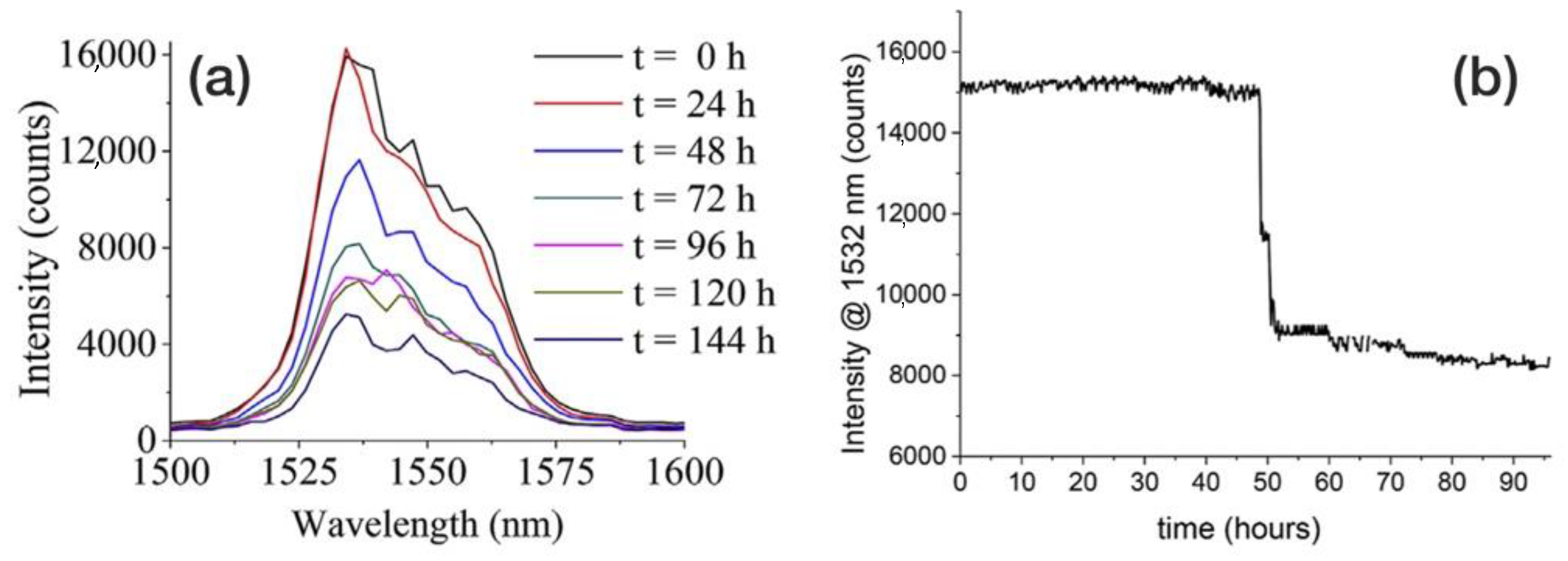
  29. Marro Bellot, C.; Olivero, M.; Sangermano, M.; Salvo, M. Towards self-diagnosis composites: Detection of moisture diffusion through epoxy by embedded evanescent wave optical fibre sensors. Polym. Test. 2018, 71, 248–254. [Google Scholar] [CrossRef]
  30. Wilson, A.R.; Muscat, R.F. Novel thin wire paint and sealant degradation sensor. Sens. Actuators A Phys. 2011, 169, 301–307. [Google Scholar] [CrossRef]
  31. Li, Y.; Feng, W.; Meng, L.; Tse, K.M.; Li, Z.; Huang, L.; Su, Z.; Guo, S. Investigation on in-situ sprayed, annealed and corona poled PVDF-TrFE coatings for guided wave-based structural health monitoring: From crystallization to piezoelectricity. Mater. Des. 2021, 199, 109415. [Google Scholar] [CrossRef]
  32. Giurgiutiu, V. Structural health monitoring with piezoelectric wafer active sensors. In Proceedings of the 16th International Conference on Adaptive Structures and Technologies, Paris, France, 9–12 October 2005; pp. 94–100. [Google Scholar]
  33. Gu, X.; Stanley, D.; Byrd, W.E.; Dickens, B.; Vaca-Trigo, I.; Meeker, W.Q.; Nguyen, T.; Chin, J.W.; Martin, J.W. Linking Accelerated Laboratory Test with Outdoor Performance Results for a Model Epoxy Coating System. In Service Life Prediction of Polymeric Materials; Springer: Boston, MA, USA, 2009. [Google Scholar]
  34. White, J.R. Polymer ageing: Physics, chemistry or engineering? Time to reflect. Comptes Rendus Chim. 2006, 9, 1396–1408. [Google Scholar] [CrossRef]
  35. Jacques, L.F.E. Accelerated and outdoor/natural exposure testing of coatings. Prog. Polym. Sci. 2000, 25, 1337–1362. [Google Scholar] [CrossRef]
  36. Deflorian, F.; Rossi, S.; Fedrizzi, L.; Zanella, C. Comparison of organic coating accelerated tests and natural weathering considering meteorological data. Prog. Org. Coat. 2007, 59, 244–250. [Google Scholar] [CrossRef]
  37. Perrin, F.X.; Merlatti, C.; Aragon, E.; Margaillan, A. Degradation study of polymer coating: Improvement in coating weatherability testing and coating failure prediction. Prog. Org. Coat. 2009, 64, 466–473. [Google Scholar] [CrossRef]
  38. Perrin, F.X.; Irigoyen, M.; Aragon, E.; Vernet, J.L. Evaluation of accelerated weathering tests for three paint systems: A comparative study of their aging behaviour. Polym. Degrad. Stab. 2001, 72, 115–124. [Google Scholar] [CrossRef]
  39. Lyon, S.B.; Bingham, R.; Mills, D.J. Advances in corrosion protection by organic coatings: What we know and what we would like to know. Prog. Org. Coat. 2017, 102, 2–7. [Google Scholar] [CrossRef] [Green Version]
  40. Skerry, B.S.; Simpson, C.H. Corrosion and Weathering of Paints for Atmospheric Corrosion Control. Corrosion 2010, 49, 663–674. [Google Scholar] [CrossRef]
  41. Kenny, E.D.; Paredes, R.S.C.; de Lacerda, L.A.; Sica, Y.C.; de Souza, G.P.; Lázaris, J. Artificial neural network corrosion modeling for metals in an equatorial climate. Corros. Sci. 2009, 51, 2266–2278. [Google Scholar] [CrossRef]
  42. Ma, T.N.G.; Abu, A.J. A field study of outdoor atmospheric corrosion rates of mild steel around Kaduna metropolis. Int. J. Mech. Eng. 2018, 5, 7–21. [Google Scholar] [CrossRef]
  43. Guerguer, M.; Naamane, S.; Raccurt, O.; Bouaouine, H. Neural network modeling of Moroccan weather conditions effect on solar reflectors degradation. AIP Conf. Proc. 2020, 2303, 150008. [Google Scholar]
  44. Popova, K.; Prošek, T. Corrosion Monitoring in Atmospheric Conditions: A Review. Metals 2022, 12, 171. [Google Scholar] [CrossRef]
  45. Nordhorn, C.; Mücke, R.; Mack, D.E.; Vaßen, R. Probabilistic lifetime model for atmospherically plasma sprayed thermal barrier coating systems. Mech. Mater. 2016, 93, 199–208. [Google Scholar] [CrossRef]
  46. Tian, W.; Meng, F.; Liu, L.; Li, Y.; Wang, F. Lifetime prediction for organic coating under alternating hydrostatic pressure by artificial neural network. Sci. Rep. 2017, 7, 40827. [Google Scholar] [CrossRef] [Green Version]
  47. Olivier, M.G.; Fedel, M.; Sciamanna, V.; Vandermiers, C.; Motte, C.; Poelman, M.; Deflorian, F. Study of the effect of nanoclay incorporation on the rheological properties and corrosion protection by a silane layer. Prog. Org. Coat. 2011, 72, 15–20. [Google Scholar] [CrossRef]
  48. Upadhyay, V.; Allahar, K.N.; Bierwagen, G.P. Environmental humidity influence on a topcoat/Mg-rich primer system with embedded electrodes. Sens. Actuators B Chem. 2014, 193, 522–529. [Google Scholar] [CrossRef]
  49. Su, Y.; Kravets, V.G.; Wong, S.L.; Waters, J.; Geim, A.K.; Nair, R.R. Impermeable barrier films and protective coatings based on reduced graphene oxide. Nat. Commun. 2014, 5, 4843. [Google Scholar] [CrossRef] [PubMed]
  50. Sørensen, P.A.; Kiil, S.; Dam-Johansen, K.; Weinell, C.E. Anticorrosive coatings: A review. J. Coat. Technol. Res. 2009, 6, 135–176. [Google Scholar] [CrossRef]
  51. Linossier, I.; Gaillard, F.; Romand, M.; Nguyen, T. A Spectroscopic Technique for Studies of Water Transport along the Interface and Hydrolytic Stability of Polymer/Substrate Systems. J. Adhes. 1999, 70, 221–239. [Google Scholar] [CrossRef]
  52. Tator, K.B.; Lanterman, R. Coating deterioration: A mechanistic overview. In Proceedings of the CORROSION 2016, Vancouver, BC, Canada, 6–10 March 2016; pp. 1–12. [Google Scholar]
  53. ISO 12944; Corrosion Protection of Steel Structures by Protective Paint Systems. International Standards Organization: Geneve, Switzerland, 1998.
  54. Han, Y.; Wang, J.; Zhang, H.; Zhao, S.; Ma, Q.; Wang, Z. Electrochemical impedance spectroscopy (EIS): An efficiency method to monitor resin curing processes. Sens. Actuators A Phys. 2016, 250, 78–86. [Google Scholar] [CrossRef]
  55. Miszczyk, A.; Miszczyk, A.; Schauer, T. Electrochemical approach to evaluate the interlayer adhesion of organic coatings Article in Progress in Organic Coatings · April 2005 Tworzywa konstrukcyjne odporne na gorące kwasy mineralne 1990 View project Chemometrics methods in corrosion View project. Prog. Org. Coat. 2005, 52, 298–305. [Google Scholar] [CrossRef]
  56. Moreno, C.; Hernández, S.; Santana, J.J.; González-Guzmán, J.; Souto, R.M.; González, S. Characterization of water uptake by organic coatings used for the corrosion protection of steel as determined from capacitance measurements. Int. J. Electrochem. Sci. 2012, 7, 7390–7403. [Google Scholar]
  57. Hu, J.M.; Zhang, J.Q.; Cao, C.N. Determination of water uptake and diffusion of Cl-ion in epoxy primer on aluminum alloys in NaCl solution by electrochemical impedance spectroscopy. Prog. Org. Coat. 2003, 46, 273–279. [Google Scholar] [CrossRef]
  58. Duarte, R.G.; Castela, A.S.; Ferreira, M.G.S. A new model for estimation of water uptake of an organic coating by EIS: The tortuosity pore model. Prog. Org. Coat. 2009, 65, 197–205. [Google Scholar] [CrossRef]
  59. Nguyen, A.S.; Causse, N.; Musiani, M.; Orazem, M.E.; Pébère, N.; Tribollet, B.; Vivier, V. Determination of water uptake in organic coatings deposited on 2024 aluminium alloy: Comparison between impedance measurements and gravimetry. Prog. Org. Coat. 2017, 112, 93–100. [Google Scholar] [CrossRef] [Green Version]
  60. Deflorian, F.; Fedrizzi, L. Adhesion characterization of protective organic coatings by electrochemical impedance spectroscopy. J. Adhes. Sci. Technol. 1999, 13, 629–645. [Google Scholar] [CrossRef]
  61. Hinton, A.J. Determination of coating adhesion using electrochemical impedance spectroscopy. Solartron Anal. 2010, 2, 18–23. [Google Scholar]
  62. Hu, J.; Li, X.; Gao, J.; Zhao, Q. UV aging characterization of epoxy varnish coated steel upon exposure to artificial weathering environment. Mater. Des. 2009, 30, 1542–1547. [Google Scholar] [CrossRef]
  63. Kittel, J.; Celati, N.; Keddam, M.; Takenouti, H. New methods for the study of organic coatings by EIS: New insights into attached and free films. Prog. Org. Coat. 2001, 41, 93–98. [Google Scholar] [CrossRef]
  64. Armas, R.A.; Gervasi, C.A.; Di Sarli, A.; Real, S.G.; Vilche, J.R. Zinc-rich paints on steels in artificial seawater by electrochemical impedance spectroscopy. Corrosion 1992, 48, 379–383. [Google Scholar] [CrossRef]
  65. Beiro, M.; Collazo, A.; Izquierdo, M.; Nóvoa, X.R.; Pérez, C. Characterisation of barrier properties of organic paints: The zinc phosphate effectiveness. Prog. Org. Coat. 2003, 46, 97–106. [Google Scholar] [CrossRef]
  66. Bierwagen, G.; Tallman, D.; Li, J.; He, L.; Jeffcoate, C. EIS studies of coated metals in accelerated exposure. Prog. Org. Coat. 2003, 46, 149–158. [Google Scholar] [CrossRef]
  67. Ribeiro, D.V.; Souza, C.A.C.; Abrantes, J.C.C. Use of Electrochemical Impedance Spectroscopy (EIS) to monitoring the corrosion of reinforced concrete. Rev. IBRACON Estrut. Mater. 2015, 8, 529–546. [Google Scholar] [CrossRef]
  68. Gamry, I. Basics of Electrochemical Impedance Spectroscopy. Available online: https://www.gamry.com/assets/Application-Notes/Basics-of-EIS.pdf (accessed on 1 April 2022).
  69. Allahar, K.N.; Bierwagen, G.; Battocchi, D.; Gelling, V.J. Examination of the feasibility of the use of in-situ corrosion sensors in army vehicules. In Proceedings of the Tri-Service Corrosion Conference, Houston, TX, USA, 14–18 November 2005. [Google Scholar]
  70. Brasher, D.M.; Kingsbury, A.H. Electrical measurements in the study of immersed paint coatings on metal. I. Comparison between capacitance and gravimetric methods of estimating water-uptake. J. Appl. Chem. 1954, 4, 62–72. [Google Scholar] [CrossRef]
  71. Le Thu, Q.; Takenouti, H.; Touzain, S. EIS characterization of thick flawed organic coatings aged under cathodic protection in seawater. Electrochim. Acta 2006, 51, 2491–2502. [Google Scholar] [CrossRef]
  72. Amirudin, A.; Thieny, D. Application of electrochemical impedance spectroscopy to study the degradation of polymer-coated metals. Prog. Org. Coat. 1995, 26, 1–28. [Google Scholar] [CrossRef]
  73. Bierwagen, G.; Wang, X.; Tallman, D. In situ study of coatings using embedded electrodes for ENM measurements. Prog. Org. Coat. 2003, 46, 163–175. [Google Scholar] [CrossRef]
  74. Merten, B.E.; Battocchi, D.; Tallman, D.E.; Bierwagen, G.P. Embedded Reference Electrode for Potential-Monitoring of Cathodic Protective Systems. J. Electrochem. Soc. 2010, 157, C244. [Google Scholar] [CrossRef]
  75. Davis, G. EIS-based in-situ sensor for the early detection of coating degradation and substrate corrosion. In Proceedings of the CORROSION 2000, Orlando, FL, USA, 26–31 March 2000. [Google Scholar]
  76. Davis, G.D.; Dacres, C.M. Electrochemical Sensors for Evaluating Corrosion and Adhesion on Painted Metal Structures. U.S. Patent 5,859,537, 12 January 1999. [Google Scholar]
  77. Davis, G.D.; Dacres, C.M.; Krebs, L.A. In-situ corrosion sensor for coating testing and screening. Mater. Perform. 2000, 39, 46–50. [Google Scholar]
  78. Davis, G.D.; Ross, R.A.; Raghu, S.D. Coating health monitoring system for army ground vehicles. In Proceedings of the CORROSION 2007, Nashville, TN, USA, 11–15 March 2007. [Google Scholar]
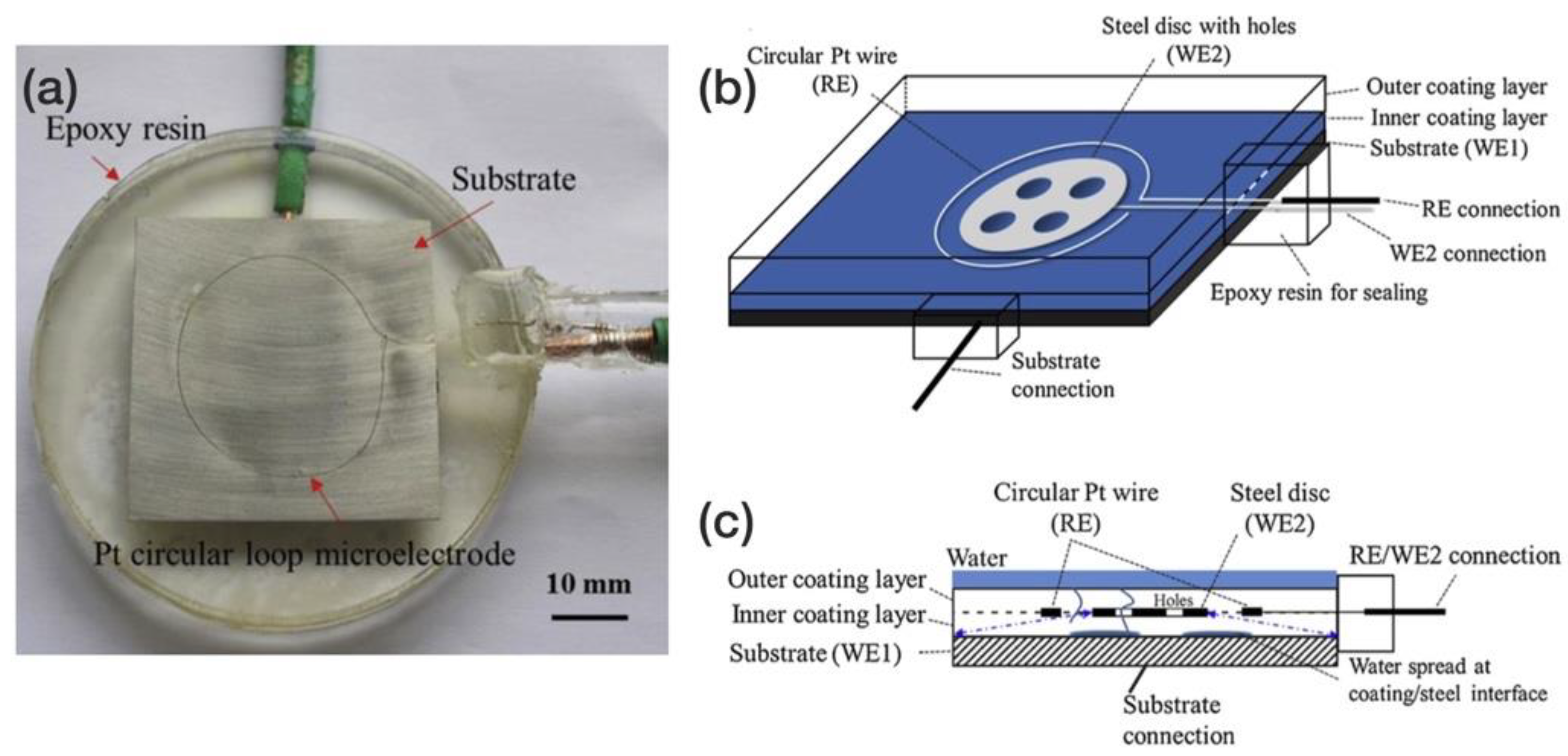
  79. Kittel, J.; Celati, N.; Keddam, M.; Takenouti, H. Influence of the coating-substrate interactions on the corrosion protection: Characterisation by impedance spectroscopy of the inner and outer parts of a coating. Prog. Org. Coat. 2003, 46, 135–147. [Google Scholar] [CrossRef]
  80. Duarte, R.G.; Castela, A.S.; Ferreira, M.G.S. Influence of the solution cation mobility on the water uptake estimation of PVC Plastisol freestanding films by EIS. Prog. Org. Coat. 2006, 57, 408–415. [Google Scholar] [CrossRef]
  81. Bierwagen, G.P.; Allahar, K.N.; Su, Q.; Gelling, V.J. Electrochemically characterizing the ac–dc–ac accelerated test method using embedded electrodes. Corros. Sci. 2009, 51, 95–101. [Google Scholar] [CrossRef]
  82. Allahar, K.; Su, Q.; Bierwagen, G. Non-substrate EIS monitoring of organic coatings with embedded electrodes. Prog. Org. Coat. 2010, 67, 180–187. [Google Scholar] [CrossRef]
  83. Brossia, C.S. Apparatus and Method for Detecting the Degradation of a Coating Using Embedded Sensors. U.S. Patent 6,911,828B1, 23 May 2005. [Google Scholar]
  84. De Rosa, R.L.; Earl, D.A.; Bierwagen, G.P. Statistical evaluation of EIS and ENM data collected for monitoring corrosion barrier properties of organic coatings on Al-2024-T3. Corros. Sci. 2002, 44, 1607–1620. [Google Scholar] [CrossRef]
  85. Iverson, W.P. Transient Voltage Changes Produced in Corroding Metals and Alloys. J. Electrochem. Soc. 1968, 115, 617. [Google Scholar] [CrossRef]
  86. Skerry, B.S.; Eden, D.A. Characterisation of coatings performance using electrochemical noise analysis. Prog. Org. Coat. 1991, 19, 379–396. [Google Scholar] [CrossRef]
  87. Bierwagen, G.P. Calculation of Noise Resistance from Simultaneous Electrochemical Voltage and Current Noise Data. J. Electrochem. Soc. 1994, 141, L155. [Google Scholar] [CrossRef]
  88. Cottis, R.A. Electrochemical noise for corrosion monitoring. In Techniques for Corrosion Monitoring; Woodhead Publishing Series in Metals and Surface Engineering; Elsevier: Cambridge, UK, 2021; pp. 99–122. [Google Scholar]
  89. Bertocci, U. Noise Resistance Applied to Corrosion Measurements. J. Electrochem. Soc. 1997, 144, 37. [Google Scholar] [CrossRef]
  90. Jamali, S.; Mills, D.J.; Woodcock, C. Ways of increasing the effectiveness of the electrochemical noise method for assessment of organic coatings on metal. ECS Trans. 2010, 24, 115–125. [Google Scholar] [CrossRef]
  91. Rodriguez-Pardo, L.; Cao-Paz, A.; Fariña, J.; Covelo, A.; Nóvoa, X.R.; Pérez, C. Water uptake kinetics in anti-corrosion organic films with a high resolution microbalance oscillator sensor. Sens. Actuators B Chem. 2010, 144, 443–449. [Google Scholar] [CrossRef]
  92. Mabbutt, S.J.; Mills, D.J. Technical note Novel configurations for electrochemical noise measurements. Br. Corros. J. 1998, 33, 158–160. [Google Scholar] [CrossRef]
  93. Mabbutt, S.; Mills, D.J.; Woodcock, C.P. Developments of the electrochemical noise method (ENM) for more practical assessment of anti-corrosion coatings. Prog. Org. Coat. 2007, 59, 192–196. [Google Scholar] [CrossRef] [Green Version]
  94. Mills, D.J.; Broster, M.; Razaq, I. Continuing work to enable electrochemical methods to be used to monitor the performance of organic coatings in the field. Prog. Org. Coat. 2008, 63, 267–271. [Google Scholar] [CrossRef]
  95. Su, Q.; Allahar, K.; Bierwagen, G. Embedded electrode electrochemical noise monitoring of the corrosion beneath organic coatings induced by ac–dc–ac conditions. Electrochim. Acta 2008, 53, 2825–2830. [Google Scholar] [CrossRef]
  96. Allahar, K.N.; Upadhyay, V.; Bierwagen, G.P.; Gelling, V.J. Monitoring of a military vehicle coating under prohesion exposure by embedded sensors. Prog. Org. Coat. 2009, 65, 142–151. [Google Scholar] [CrossRef]
  97. Telegdi, J.; Shaban, A.; Vastag, G. Biocorrosion—Steel. In Encyclopedia of Interfacial Chemistry; Elsevier: New York, NY, USA, 2018; pp. 28–42. [Google Scholar]
  98. Rahman, S.U.; Atta Ogwu, A. Corrosion and Mott-Schottky probe of chromium nitride coatings exposed to saline solution for engineering and biomedical applications. In Advances in Medical and Surgical Engineering; Elsevier: London, UK, 2020; pp. 239–265. [Google Scholar]
  99. Shin, C.-S.; Liaw, S.-K.; Yang, S.-W. Post-Impact Fatigue Damage Monitoring Using Fiber Bragg Grating Sensors. Sensors 2014, 14, 4144–4153. [Google Scholar] [CrossRef] [PubMed] [Green Version]
  100. Deng, F.; Huang, Y.; Azarmi, F.; Wang, Y. Pitted Corrosion Detection of Thermal Sprayed Metallic Coatings Using Fiber Bragg Grating Sensors. Coatings 2017, 7, 35. [Google Scholar] [CrossRef] [Green Version]
  101. Ramezani-Dana, H.; Casari, P.; Perronnet, A.; Fréour, S.; Jacquemin, F.; Lupi, C. Hygroscopic strain measurement by fibre Bragg gratings sensors in organic matrix composites - Application to monitoring of a composite structure. Compos. Part B Eng. 2014, 58, 76–82. [Google Scholar] [CrossRef]
  102. Enser, H.; Sell, J.K.; Hilber, W.; Jakoby, B. Printed strain sensors in organic coatings: In depth analysis of sensor signal effects. Sens. Actuators A Phys. 2018, 281, 258–263. [Google Scholar] [CrossRef]
  103. Enser, H.; Kulha, P.; Sell, J.K.; Schatzl-Linder, M.; Strauß, B.; Hilber, W.; Jakoby, B. Printed strain gauges embedded in organic coatings—Analysis of gauge factor and temperature dependence. Sens. Actuators A Phys. 2018, 276, 137–143. [Google Scholar] [CrossRef]
  104. Enser, H.; Kulha, P.; Sell, J.K.; Jakoby, B.; Hilber, W.; Strauß, B.; Schatzl-Linder, M. Printed Strain Gauges Embedded in Organic Coatings. Procedia Eng. 2016, 168, 822–825. [Google Scholar] [CrossRef]
  105. Kulha, P.; Enser, H.; Sell, J.K.; Strauß, B.; Schatzl-Linder, M.; Jakoby, B.; Hilber, W. Temperature dependence of gauge factor of printed piezoresistive layers embedded in organic coatings. Proceedings 2017, 1, 618. [Google Scholar] [CrossRef] [Green Version]
  106. Zhang, Y.; Anderson, N.; Bland, S.; Nutt, S.; Jursich, G.; Joshi, S. All-printed strain sensors: Building blocks of the aircraft structural health monitoring system. Sens. Actuators A Phys. 2017, 253, 165–172. [Google Scholar] [CrossRef] [Green Version]
  107. Zymelka, D.; Togashi, K.; Ohigashi, R.; Yamashita, T.; Takamatsu, S.; Itoh, T.; Kobayashi, T. Printed strain sensor array for application to structural health monitoring. Smart Mater. Struct. 2017, 26, 105040. [Google Scholar] [CrossRef]
  108. Sell, J.K.; Enser, H.; Jakoby, B.; Schatzl-Linder, M.; Strauss, B.; Hilber, W. Printed Embedded Transducers: Capacitive Touch Sensors Integrated into the Organic Coating of Metalic Substrates. IEEE Sens. J. 2016, 16, 7101–7108. [Google Scholar] [CrossRef]
  109. Zarifi, M.H.; Deif, S.; Daneshmand, M. Wireless passive RFID sensor for pipeline integrity monitoring. Sens. Actuators A Phys. 2017, 261, 24–29. [Google Scholar] [CrossRef]
  110. Khalifeh, R.; Yasri, M.S.; Lescop, B.; Gallee, F.; Diler, E.; Thierry, D.; Rioual, S. Development of wireless and passive corrosion sensors for material degradation monitoring in coastal zones and immersed environment. IEEE J. Ocean. Eng. 2016, 41, 776–782. [Google Scholar] [CrossRef]
  111. Muscat, R.F.; Wilson, A.R. Corrosion onset detection sensor. IEEE Sens. J. 2017, 17, 8424–8430. [Google Scholar] [CrossRef]
  112. Akpakwu, G.A.; Silva, B.J.; Hancke, G.P.; Abu-Mahfouz, A.M. A Survey on 5G Networks for the Internet of Things: Communication Technologies and Challenges. IEEE Access 2017, 6, 3619–3647. [Google Scholar] [CrossRef]
  113. Rao, S.K.; Prasad, R. Impact of 5G Technologies on Industry 4.0. Wirel. Pers. Commun. 2018, 100, 145–159. [Google Scholar] [CrossRef]
  114. Al-Falahy, N.; Alani, O.Y. Technologies for 5G Networks: Challenges and Opportunities. IT Prof. 2017, 19, 12–20. [Google Scholar] [CrossRef] [Green Version]
  115. Popov, V.V.; Kudryavtseva, E.V.; Kumar Katiyar, N.; Shishkin, A.; Stepanov, S.I.; Goel, S. Industry 4.0 and Digitalisation in Healthcare. Materials 2022, 15, 2140. [Google Scholar] [CrossRef]
  116. Parthiban, T.; Ravi, R.; Parthiban, G.T.; Srinivasan, S.; Ramakrishnan, K.R.; Raghavan, M. Neural network analysis for corrosion of steel in concrete. Corros. Sci. 2005, 47, 1625–1642. [Google Scholar] [CrossRef]
  117. Ding, L.; Rangaraju, P.; Poursaee, A. Application of generalized regression neural network method for corrosion modeling of steel embedded in soil. Soils Found. 2019, 59, 474–483. [Google Scholar] [CrossRef]
  118. Wilson, A.R.; Vincent, P.S. Networked low-power sensing: Network interface and main operating system. IEEE Sens. J. 2010, 10, 1495–1507. [Google Scholar] [CrossRef]
  119. Vincent, P.S.; McMahon, P.J.; Muscat, R.F.; Zeve, L.; Wilson, A.R. A small low-power networked and versatile sensor interface. In Smart Structures, Devices & Systems III; Al-Sarawi, S.F., Ed.; International Society for Optics and Photonics: Bellingham, WA, USA, 2006; Volume 6414, p. 64140Z. [Google Scholar]
  120. Demo, J.; Steiner, A.; Friedersdorf, F.; Putic, M.; Street, F.; Suite, A. Development of a Wireless Miniaturized Smart Sensor Network for Aircraft Corrosion Monitoring. In Proceedings of the 2010 IEEE Aerospace Conference, Big Sky, MT, USA, 6–13 March 2010. [Google Scholar]
  121. Li, Z.; Zheng, Q.; Wang, Z.L.; Li, Z. Nanogenerator-Based Self-Powered Sensors for Wearable and Implantable Electronics. Research 2020, 2020, 1–25. [Google Scholar] [CrossRef] [PubMed] [Green Version]
  122. Karabetoglu, S.; Sisman, A.; Fatih Ozturk, Z.; Sahin, T. Characterization of a thermoelectric generator at low temperatures. Energy Convers. Manag. 2012, 62, 47–50. [Google Scholar] [CrossRef]
  123. Zhang, Y.; Cleary, M.; Wang, X.; Kempf, N.; Schoensee, L.; Yang, J.; Joshi, G.; Meda, L. High-temperature and high-power-density nanostructured thermoelectric generator for automotive waste heat recovery. Energy Convers. Manag. 2015, 105, 946–950. [Google Scholar] [CrossRef] [Green Version]
  124. Wang, X.; Liang, L.; Lv, H.; Zhang, Y.; Chen, G. Elastic aerogel thermoelectric generator with vertical temperature-difference architecture and compression-induced power enhancement. Nano Energy 2021, 90, 106577. [Google Scholar] [CrossRef]
  125. Kim, D.K.; Duan, C.; Chen, Y.F.; Majumdar, A. Power generation from concentration gradient by reverse electrodialysis in ion-selective nanochannels. Microfluid. Nanofluid. 2010, 9, 1215–1224. [Google Scholar] [CrossRef]
  126. Wang, Z.L. Triboelectric nanogenerators as new energy technology and self-powered sensors–Principles, problems and perspectives. Faraday Discuss. 2014, 176, 447–458. [Google Scholar] [CrossRef]
  127. El-hami, M.; Glynne-Jones, P.; White, N.M.; Hill, M.; Beeby, S.; James, E.; Brown, A.D.; Ross, J.N. Design and fabrication of a new vibration-based electromechanical power generator. Sens. Actuators A Phys. 2001, 92, 335–342. [Google Scholar] [CrossRef]
  128. Wu, C.; Liu, R.; Wang, J.; Zi, Y.; Lin, L.; Wang, Z.L. A spring-based resonance coupling for hugely enhancing the performance of triboelectric nanogenerators for harvesting low-frequency vibration energy. Nano Energy 2017, 32, 287–293. [Google Scholar] [CrossRef]
  129. Siddique, A.R.M.; Mahmud, S.; Van Heyst, B. A comprehensive review on vibration based micro power generators using electromagnetic and piezoelectric transducer mechanisms. Energy Convers. Manag. 2015, 106, 728–747. [Google Scholar] [CrossRef]
  130. Pommersheim, J.M.; Nguyen, T.; Zhang, Z.; Hubbard, J.B. Degradation of organic coatings on steel: Mathematical models and predictions. Prog. Org. Coat. 1994, 25, 23–41. [Google Scholar] [CrossRef]
  131. Nicolai, R.P.; Budai, G.; Dekker, R.; Vreijling, M. Modeling the deterioration of the coating on steel structures: A comparison of methods. Conf. Proc.-IEEE Int. Conf. Syst. Man Cybern. 2004, 5, 4177–4182. [Google Scholar] [CrossRef]
  132. Loveday, D.; Peterson, P.; Rodgers, B. Evaluation of organic coatings with electrochemical impedance spectroscopy: Part 1: Fundamentals of electrochemical impedance spectroscopy. CoatingsTech 2004, 1, 46–52. [Google Scholar]
  133. Hinderliter, B.R.; Croll, S.G.; Tallman, D.E.; Su, Q.; Bierwagen, G.P. Interpretation of EIS data from accelerated exposure of coated metals based on modeling of coating physical properties. Electrochim. Acta 2006, 51, 4505–4515. [Google Scholar] [CrossRef]
  134. Hoksbergen, N.; Akkerman, R.; Baran, I. The Springer model for lifetime prediction of wind turbine blade leading edge protection systems: A review and sensitivity study. Materials 2022, 15, 1170. [Google Scholar] [CrossRef]
  135. Domenech, L.; Renau, J.; Šakalyte, A.; Sánchez, F. Top coating anti-erosion performance analysis in wind turbine blades depending on relative acoustic impedance. Part 1: Modelling approach. Coatings 2020, 10, 685. [Google Scholar] [CrossRef]
  136. Herring, R.; Domenech, L.; Renau, J.; Šakalytė, A.; Ward, C.; Dyer, K.; Sánchez, F. Assessment of a wind turbine blade erosion lifetime prediction model with industrial protection materials and testing methods. Coatings 2021, 11, 767. [Google Scholar] [CrossRef]
Figure 1. The types of environments that are encountered by anticorrosion coatings [50].
Coatings 12 00565 g001
Figure 2. A scheme of the traditional benchtop EIS configuration and setup (personal drawing; inspiration from [73,74]).
Coatings 12 00565 g002
Figure 3. (a) The in-situ EIS sensor for measurements in the field. (b) The hand-held version of the EIS sensor for measurements in the field (personal drawing; inspiration from [76]).
Coatings 12 00565 g003
Figure 4. (a) The evolution of low-frequency impedance with exposure time of coated metal samples. (b) The impedance becomes independent from the frequency as the coating deteriorates [76].
Coatings 12 00565 g004
Figure 5. (a) An illustration of the miniaturised coating health monitor with tape electrodes. (b) A comparison to a conventional flat cell for EIS measurements [78].
Coatings 12 00565 g005
Figure 6. (a) An example of an effective coating showing high stable electrochemical impedance and a metallic substrate in good condition Vs. (b) an ineffective coating with low impedance and generalised corrosion on the substrate. (c) State of degradation of the NLR2A system corrosion after 36 days. (d) State of degradation of the KP1 system corrosion after 31 days [78].
Coatings 12 00565 g006
Figure 7. (a) Traditional EIS measurement in the field. (b) A mark on the coating where a traditional EIS cell was attached for measurement in the field [75].
Coatings 12 00565 g007
Figure 8. The evolution of configurations used for EIS measurements (ad). (Personal drawing; inspiration from [73,74]).
Coatings 12 00565 g008
Figure 9. The schematics of a non-substrate two-electrode EIS measurement between two embed-ded electrodes and the five possible current flow pathways at low frequency, where, according to authors, “Path A involves passing through the electrode/coating interface, the base coating and the coating/substrate interface for each electrode and passing through the metal. Path B involves passing between the electrodes through the top coat/primer interlayer. Path C involves passage through the electrode/coating interface, the top coat of each electrode and passage through the electrolyte on the surface of the coating. Path D involves passage through the electrode/primer interface and through the primer, while Path E involves passage through the electrode/topcoat interface and through the topcoat”. Reprinted with permission from ref. [82], Elsevier, 2010.
Coatings 12 00565 g009
Figure 10. The traditional configuration for benchtop ENM measurement (personal drawing; inspiration from [92]).
Coatings 12 00565 g010
Figure 11. (a) The reverse configuration and (b) the schematics of the three-electrode, no substrate connection (personal drawing; inspiration from [92]).
Coatings 12 00565 g011
Figure 12. An illustration of the surface-attached ENM montage Reprinted with permission from ref. [94]. Elsevier, 2008.
Coatings 12 00565 g012
Figure 13. An illustration of electrodes embedded in Pt coating for ENM measurement. Reprinted with permission from ref. [95]. Elsevier, 2008.
Coatings 12 00565 g013
Figure 14. (a) A digital image of an EE montage for ENM measurement with an embedded Pt microelectrode at the metal–resin interface. (b) The schematics of the same montage, (c) Cut of the same set-up. Reprinted with permission from ref. [69]. Elsevier, 2019.
Coatings 12 00565 g014
Figure 15. A schematic of the response of FBG to an applied strain [100].
Coatings 12 00565 g015
Figure 16. (a) The evolution of light reflected by an embedded OFS with time. (b) An OFS signal drop due to water diffusion through the surrounding coating [29].
Coatings 12 00565 g016
Figure 17. (a) A schematic of multiple OFSs embedded at different depths in an epoxy sample. (b) A digital image of a sample with two embedded OFSs. Reprinted with permission from ref. [29]. Elsevier, 2018.
Coatings 12 00565 g017
Figure 18. The schematics of screen-printed strain gauges in between coating layers. (1) Sheet steel. (2) Organic primer pre-applied factory side. (3) Screen-printed silver/carbon black strain gauge. (4) Top coating layer for mechanical protection and stabilization. Reprinted with permission from ref. [104]. Elsevier, 2018.
Coatings 12 00565 g018
Figure 19. (a) A simple equivalent circuit illustration, known as Randle’s circuit. (b) An equivalent circuit considering the influence of the interphase [134].
Coatings 12 00565 g019
Figure 20. The Springer model overview [134].
Coatings 12 00565 g020
Table 1. The summary table for all of the reviewed embedding techniques for the monitoring of organic coatings.
Targeted Coating PropertiesTechnologyAdvantages/DrawbacksTele-Operated Yet
Electrochemical propertiesEISVersatile; very well-known/Prone to noise; affected by electromagnetic fields; very complex data analysisYes
ENMQuicker data gathering; less intrusive/Very complex theoretical background; affected by electromagnetic fieldsYes
Internal stress–strain stateOptical fibres (FBGs)Well-known technology; high sensitivity/Difficult to embed; fragile; affected by temperatureYes/No
Piezoresistive-based gaugesSimple yet versatile; easy to fabricate; easy data handling and interpretation; high sensitivity/Affected by temperature No
OthersMagnetic nanoparticlesSimplest deployment/Need for a nearby device to interrogate the system through the application of a strong magnetic field; very nicheNo
RFIDLow-cost; unpowered; wireless/Difficult to embed; niche; only tested on buried pipesNo
Conductive wiresSimple; easy to operate/May be invasive when embeddedYes
Publisher’s Note: MDPI stays neutral with regard to jurisdictional claims in published maps and institutional affiliations.

