Article

Fabrication and Performance Analysis of 3D Inkjet Flexible Printed Touch Sensor Based on AgNP Electrode for Infotainment Display

by
Srinivasan Palanisamy
1,
Muthuramalingam Thangaraj
1,*,
Khaja Moiduddin
2,* and
Abdulrahman M. Al-Ahmari
3
1
Department of Mechatronics Engineering, SRM Institute of Science and Technology, SRM Nagar, Kattankulathur, Chennai 603203, India
2
Advanced Manufacturing Institute, King Saud University, Riyadh 11421, Saudi Arabia
3
Raytheon Chair for Systems Engineering (RCSE Chair), Advanced Manufacturing Institute, King Saud University, Riyadh 11421, Saudi Arabia
*
Authors to whom correspondence should be addressed.
Coatings 2022, 12(3), 416; https://doi.org/10.3390/coatings12030416
Submission received: 10 February 2022 / Revised: 18 March 2022 / Accepted: 18 March 2022 / Published: 21 March 2022

Abstract

:
It is possible to employ printed capacitive sensors in car bezel applications because of its lower cost and higher detecting capabilities. In this paper, a flexible sensor for automotive entertainment applications has been developed using an electrode flexible sensor with an interdigitated pattern printed on it using screen printing and 3D printing fabrication processes. Design concerns such as electrode overlap, electrode gap and width on capacitance changes, and production costs were studied. In addition, a new generation of flexible printed sensors has been developed that can outperform conventional human–machine interface (HMI) sensors. The capacitance of the design pattern may be optimized by using a 15mm overlap and 0.5mm electrode line width. Due to the precision of interpolation, overlap has a larger effect on sensor performance than it would have without it.

1. Introduction

The incorporation of automotive electronics in vehicles plays a key role in improving customer expectations in terms of ergonomics, car performance, and safety. To achieve futuristic technology and passenger comfort, cockpit electronics technology should pay close attention to replacing tactile buttons and knobs with flexible touch sensors (FTS). Lightweight flexible electronics based on human–machine-interfaces (HMI) can reduce the mass of the infotainment bezel in automotive vehicles [1]. Nowadays, flexible printed sensors (FPS) are highly recommended among the automotive industry due to the increased production rates, adaptability, and capacity for complicated geometries [2,3]. Flexible sensors of this type are easily manufactured using screen printing-based technology, which has a low manufacturing cost and excellent formability for creating three-dimensional (3D) shapes necessary for smooth cockpit integration [4]. Flexible printed sensors have been discovered to be most suitable for infotainment bezels based on in-mold electronics (IME) [5]. The process of printing electronics circuitry on two-dimensional substrates and converting them to three-dimensional components involves a range of manufacturing and material problems. As a result, three-dimensional objects are formed with varying degrees of embedded circuitry. This is part of a global trend away from the straightforward solution of components in primitive box/design, such as buttons, and towards three-dimensional structural electronics. Prior to development of IME-based infotainment, experimental investigations were undertaken on the sensor’s performance.
The audio system bezel can be simply manufactured in two-dimensional or three-dimensional shapes utilizing the IME method in line with the ECE R21 standard for automobiles. The ECE R21 specifies consistent requirements for vehicle certification in terms of interior fittings, such as dashboards, steering wheels, seats, and roofs. The ECE R21 provides that, in general, all knobs, switches, and levers on the I/P must meet the following requirements: if projection is less than 3.2 mm, radii must be >0.5 mm and H/W ratio must be <0.5; if projection is >3.2 mm but <9.5 mm, radii must be >2.5 mm, and surface area must be >200 mm2; if projection is >9.5 mm, the object must either retract or break away to a projection <9.5 mm. If it retracts, the requirements are the same as above. If it breaks away, the object must have had a surface area >650 mm2 before it broke away. The audio system HMI is divided into a mechatronics approach based on three types, as shown in Figure 1. For the silicon button with conductive pills and conductive pads on PCB, when the user pushes the button, the contact bills and conductive pads touch each other and provide circuit closure. Similarly, tactile buttons also use mechanical activation. The electronics touch principles are resistive and capacitive [6].
As resistive touch panels do not support multiple touch point signs and have no IME adaptability, it is suggested to use the capacitive-based FTS in car bezels for infotainment applications. Capacitive touch screen sensors can be made with insulated plastic sheets and conductive ink materials. The conductive ink pattern can be created using either an unbroken conductivity line path pattern or an interdigitated pattern based on two isolated conductive electrodes [7,8,9]. Two conductive ink pattern electrodes isolated by dielectric medium are used to create such flexible printed capacitive sensors. When utilized to generate FPS in audio bezel applications, nano-silver particle (AgNP) conductive materials offer a higher sensitivity and a lower wear rate than other conductive materials because of their superior physical and electrical properties [10].
The final entertainment product is constructed using flexible printed conductive layers over a hard plastic layer [11,12]. Because capacitance is directly related to the electrode overlap area in capacitive touch panels, spatial interpolation of the electrode structure has a significant effect on sensor performance [13,14]. The space between electrode structures can also affect sensitivity due to its capacity to vary capacitance. It is crucial to select the optimum overlap area and distance between electrodes while screen printing for increased sensitivity and cheaper production costs [15,16,17,18,19]. All additive processes were employed to manufacture functioning humidity sensors on PET foil. The author has fabricated a sensor including inkjet printing interdigitated structures. Inkjet sensor arrays can be employed where cost-effectiveness, low weight, and mechanical adaptability are required [20,21,22]. Additive electronics printing possibilities include inkjet, screen printing, and aerosol. Picking a printing technology for an additive electronics project might be difficult, because each one has advantages and disadvantages. Choosing the wrong technology at the start of a project might result in considerable upfront costs and time delays. Most home office printers use inkjet printing technology. Additionally, inkjet printing for prototyping additive electronics devices is digital. With no additional tooling, a new design can be printed on the spot, reducing iteration time. To create any pattern on a substrate, inkjet uses microscopic droplets ejected from hundreds of tiny nozzles on a print head. The way droplets are created varies depending on the inkjet type. While all inkjet printers are safe for home usage, not all are suited for additive electronics [23]. There are two types of inkjet: thermal and piezo. Thermal inkjet (also known as bubble jet) employs resistive heating to swiftly evaporate ink. The rapidly increasing vaporized ink inside the ink channel drives ink out of the nozzle. The major reason to avoid utilizing conductive inks with a thermal inkjet is heat. Each drop released cures a tiny amount of ink inside the nozzle, quickly blocking it. In contrast, the piezo inkjet uses piezo components to send a shockwave through the ink to eject a droplet. Piezo elements are ceramics that distort when exposed to electricity. Piezo inkjet printers use this property by transmitting voltage waveforms tailored for the fluid route geometry, the ink expelled, and the droplet size.
According to the above comprehensive survey, there were only a few studies that compared the fabrication processes of 3D (dimensional), inkjet printing (3D IJP), and screen printing (SP) against applications for automotive audio system bezels. Only a small amount of research funding has been spent to investigate the effects of electrode parameters of sensor pattern on sensor performance. As a result, the current investigation was proposed. In this work, the low-cost and flexible inkjet-printed flexible capacitive sensor (FPS) with silver nanoparticle (AgNP) ink was studied. When combined with conductive ink materials, an insulated plastic sheet is utilized to create capacitive-based FTS for usage in infotainment, as shown in Figure 1.
As illustrated in Figure 2, the fabricated one-touch flexible printed capacitive sensors, which have the lines for the reception (Rx) and transmitter (Tx), can be framed over the IME bezel. In audio system applications, the interdigitated pattern presented here can be used in place of keys on the audio bezel, saving space. The current work involved the design and production of a FPS-based interdigitated pattern-based key. When the passengers touch the capacitive key, the electric field changes due to spatial interpolation.

2. Materials and Methods

It is feasible to manufacture a sensor of this type using 3D IJP, but it was limited in scope, owing to the time required and the employed ink material. It could be utilized for prototyping and low-volume production of sensors. A conductive ink pattern for automotive applications can be constructed using either an uninterrupted conductive line path pattern or two separate conducting electrode-based interdigitated pattern. These printed integrated electrode capacitive sensors are composed of two conductive ink pattern electrodes separated by a dielectric medium. As utilized to construct FPS in audio system bezel applications, AgNP conductive materials can give increased sensitivity while also having a lower wear rate when compared to other conductive materials, owing to its excellent physical and electrical properties. AgNP ink was chosen due to its higher electrical conductivity than copper and lower cost than gold. It also has more resistance to oxidation than copper [24,25,26]. Thus, it was chosen as the track material in the present study.

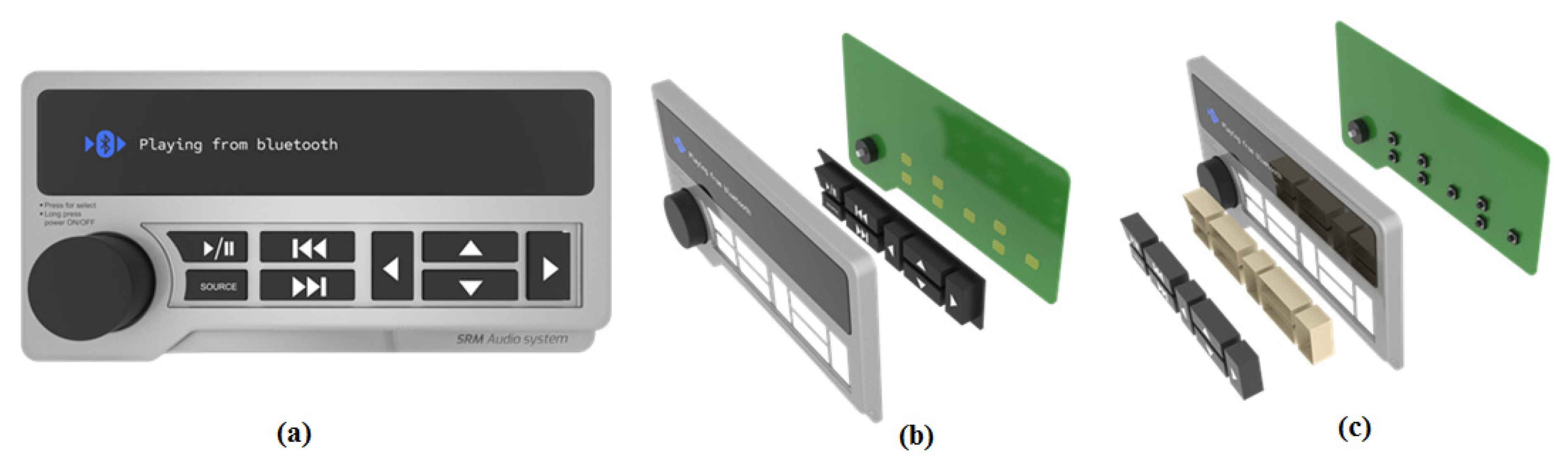
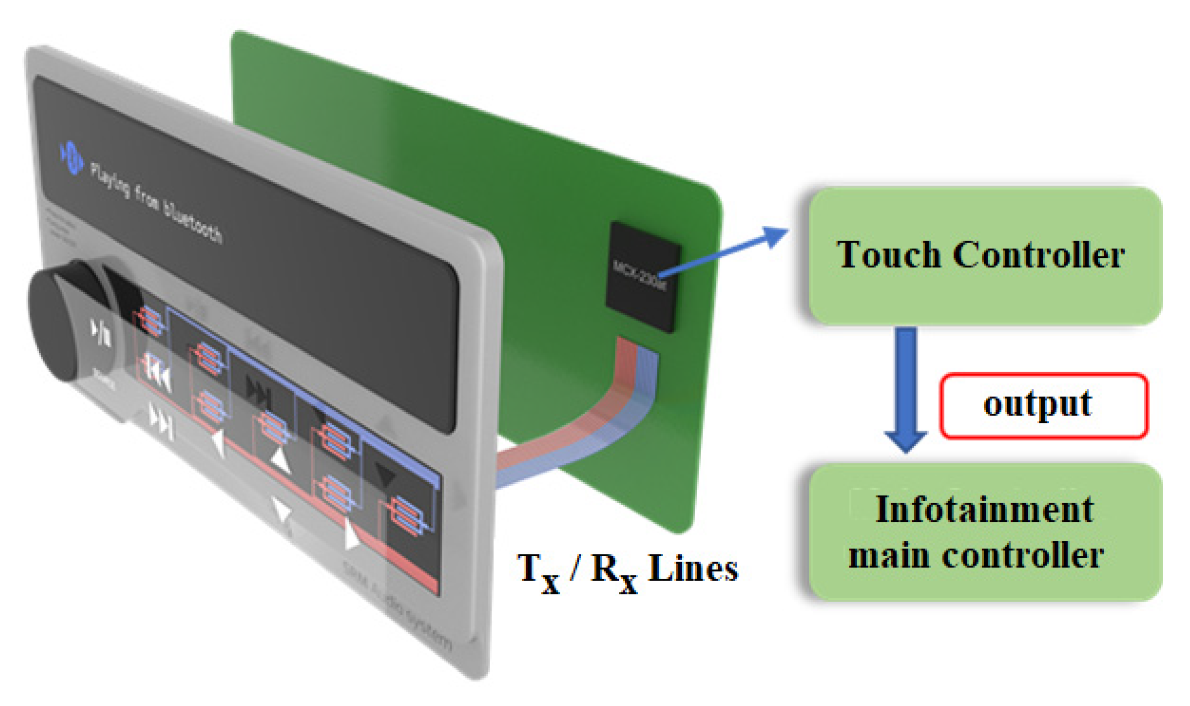
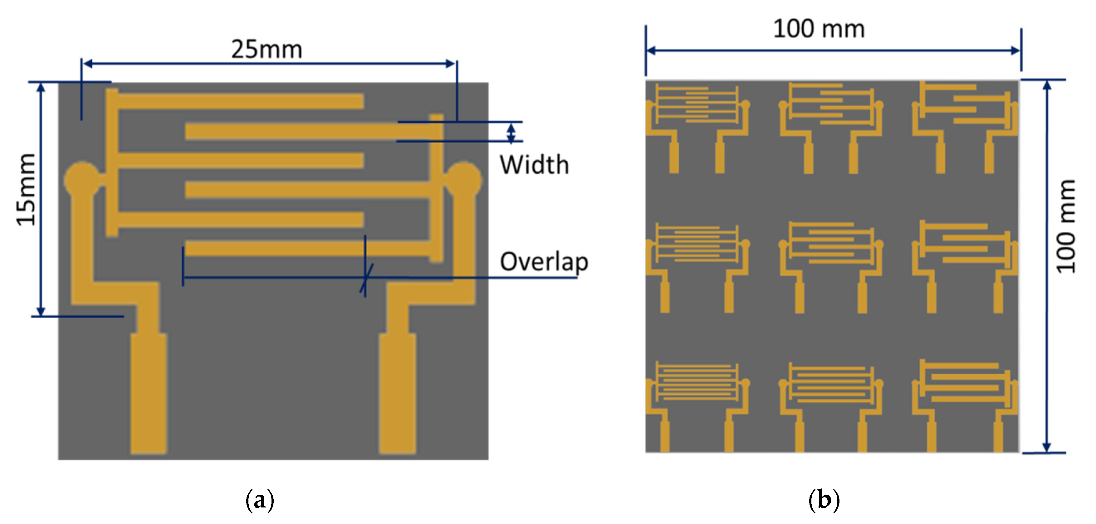
2.1. Design of 3D Inkjet Printing (IJP) of FPS

The creation of a pattern with interdigitated digits for button functionality, a printed capacitive touch panel with a 25 mm × 15 mm surface area, was constructed as indicated in Figure 3. The function can be electronically assigned to any infotainment option on the primary controller. The design of the button sensor was carried out utilizing parametric modeling and the AutoCAD 2020 version drawing software. Nine trials were chosen, since the experimental design included three input variables: overlap distance (OL) (5 mm, 10 mm, 15 mm), electrode gap (EG) (0.5 mm, 0.8 mm, 1.2 mm), and electrode line width (EL) (0.5 mm, 0.8 mm, 1.2 mm) with three distinct levels. Each specimen had the same space between the lines and the same coating thickness.

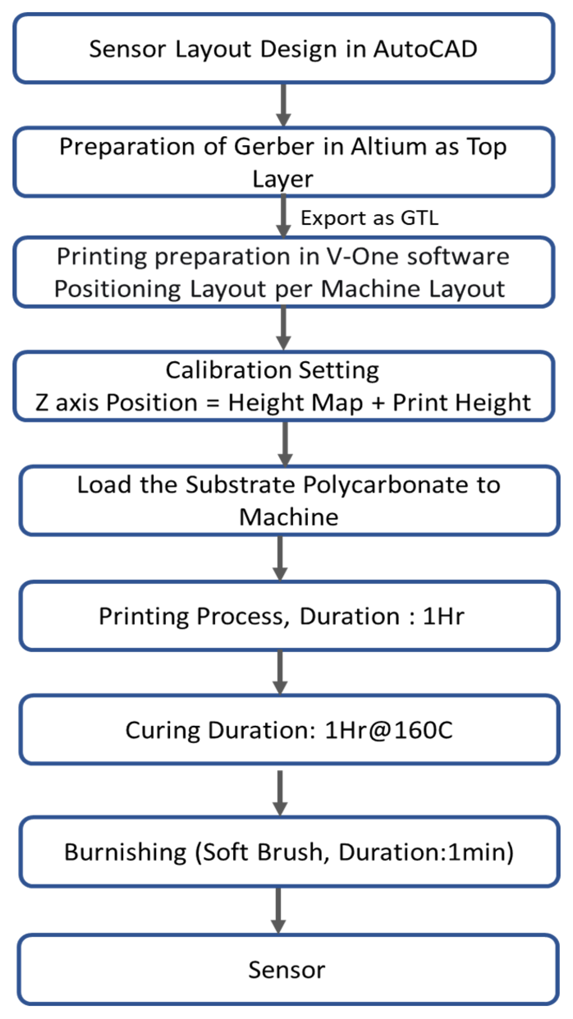
2.2. Workflow of 3D Inkjet Printing (IJP) Fabrication for Printed IDE Capacitive Sensor

AgNP conductive ink (sourced from Siltech Corporation INC, Bengaluru, India) with a solids content of 70% and a thermoplastics/additives content of 30% was used to make the electrodes for the sensors [12,22]. A PC (polycarbonate) sheet with thickness of 375 microns was coated with an on average 47-micron layer of thickness, as per the work flow diagram (Figure 4). A Voltera V-One printed circuit board (PCB) printing machine with nozzle diameter of 100 microns (manufactured by Voltera Company, Kitchener, ON, Canada) was utilized for the fabrication. The sensor layout was designed using AutoCAD 2020 version drawing software. The design layout was converted into Gerber format and fed to the calibrated Voltera PCB printing machine. After the process of 3D inkjet printing of the sensor pattern, one hour was allowed for the curing process. Then, the sensor pattern was burnished with the help of soft brush. The ink flow was performed under 5, 10, and 15 points. The coating thickness of the FPS was measured using a Bruker non-contact profiler. To determine the change in capacitance, a Keysight-manufactured U1733C Handheld 20,000 Count LCR Meter (Bengaluru, India) with dual display was utilized.

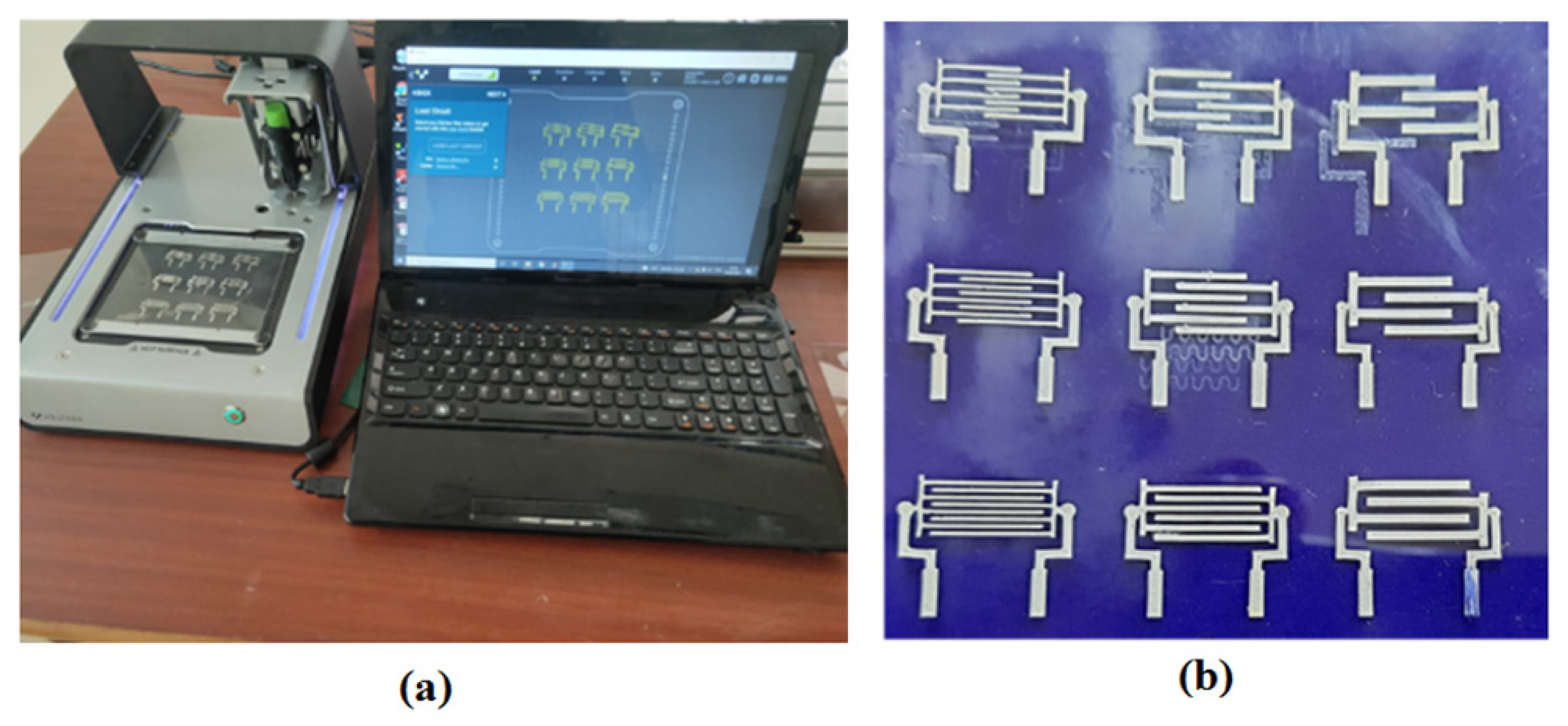
2.3. Fabrication of FPS Using Inkjet Printer

Figure 5 illustrates the fabrication of a printed IDE capacitive sensor using V-One PCB printer (Voltera Company, Kitchener, ON, Canada) with nozzle diameter of 100 microns. The ink flow was performed with 5, 10, and 15 points, as shown in Figure 5. It was observed that an ink flow of 15 points could produce better printability of FPS. The current investigation utilized experimental trials, using performance metrics as shown in Table 1, and measured the coating thickness using a Bruker non-contact profiler as illustrated in Figure 6. It was observed that the sensors were fabricated with uniform distribution in the FPS. The average coating thickness of the inkjet sensor was measured at 47 µm. The Taguchi methodology was used to design the experimental trials to be conducted for the experimental analysis in the present study. The number of trial specimens was selected as nine, since the experiment involved two input factors, such as OL (5 mm, 10 mm, 15 mm), EW (0.5 mm, 0.8 mm, 1.2 mm), and EG (0.5 mm, 0.8 mm, 1.2 mm), along with three different levels. In order to improve measurement accuracy, all trials were carried out three times, with the average of the three values being used as the final value. The Keysight U1733C 20,000 Count Handheld LCR Meter with dual display was used for measuring sensitivity using change in capacitance (ΔC) during touch, and this can be denoted in terms of pico farads (pF).

3. Results and Discussion

3.1. Verification of Printed FPS

The TTP223 is a touch-sensitive integrated circuit that generates one touch key when it detects the presence of a touch. When a touch is made, capacitance decreases in proportion to the CMOS output voltage [27,28]. This circuit’s output is converted to the on/off state of an LED. When a finger contacts the sensor, the LED can be illuminated based on spatial interpolation, as illustrated in Figure 7.

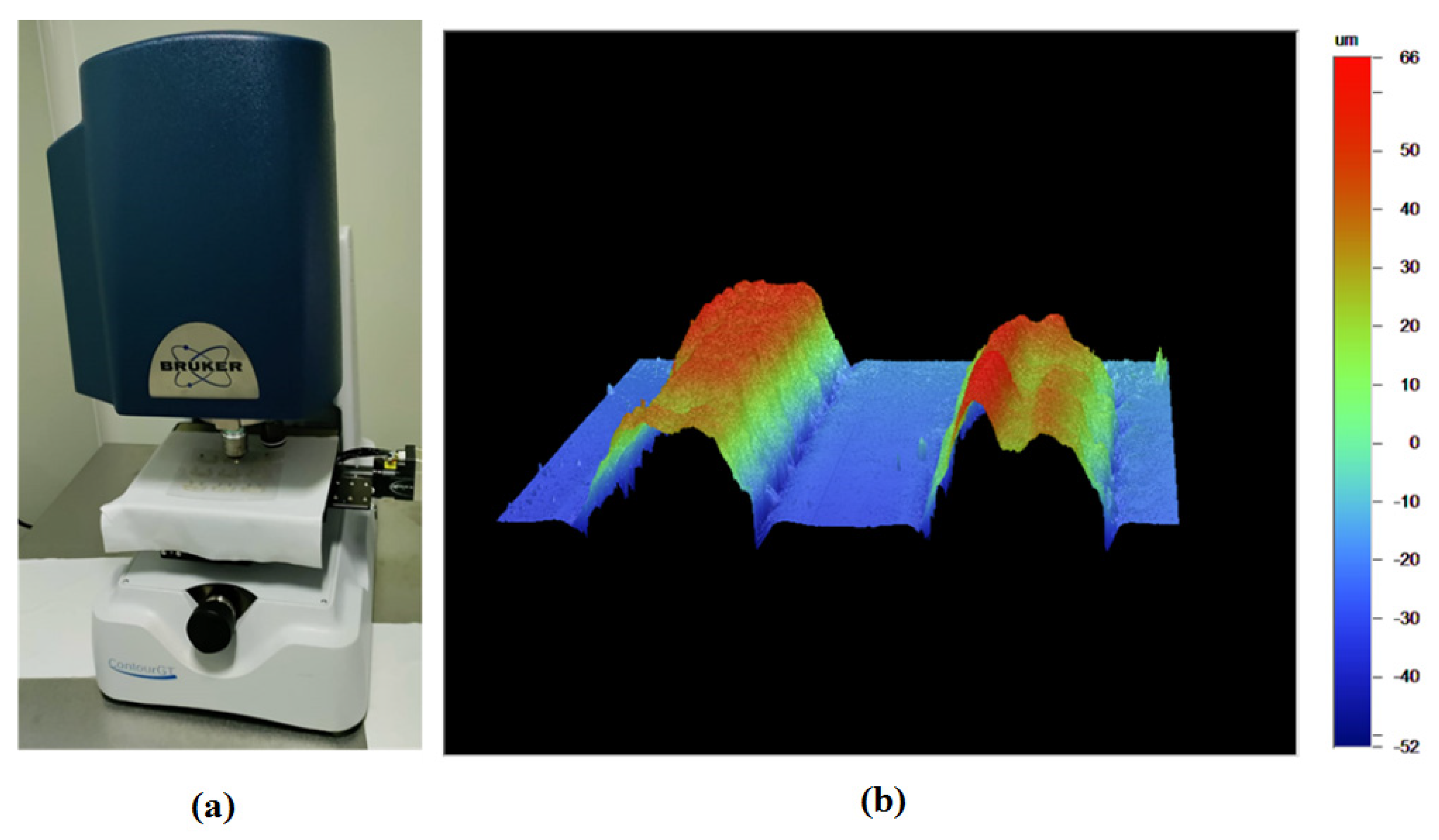
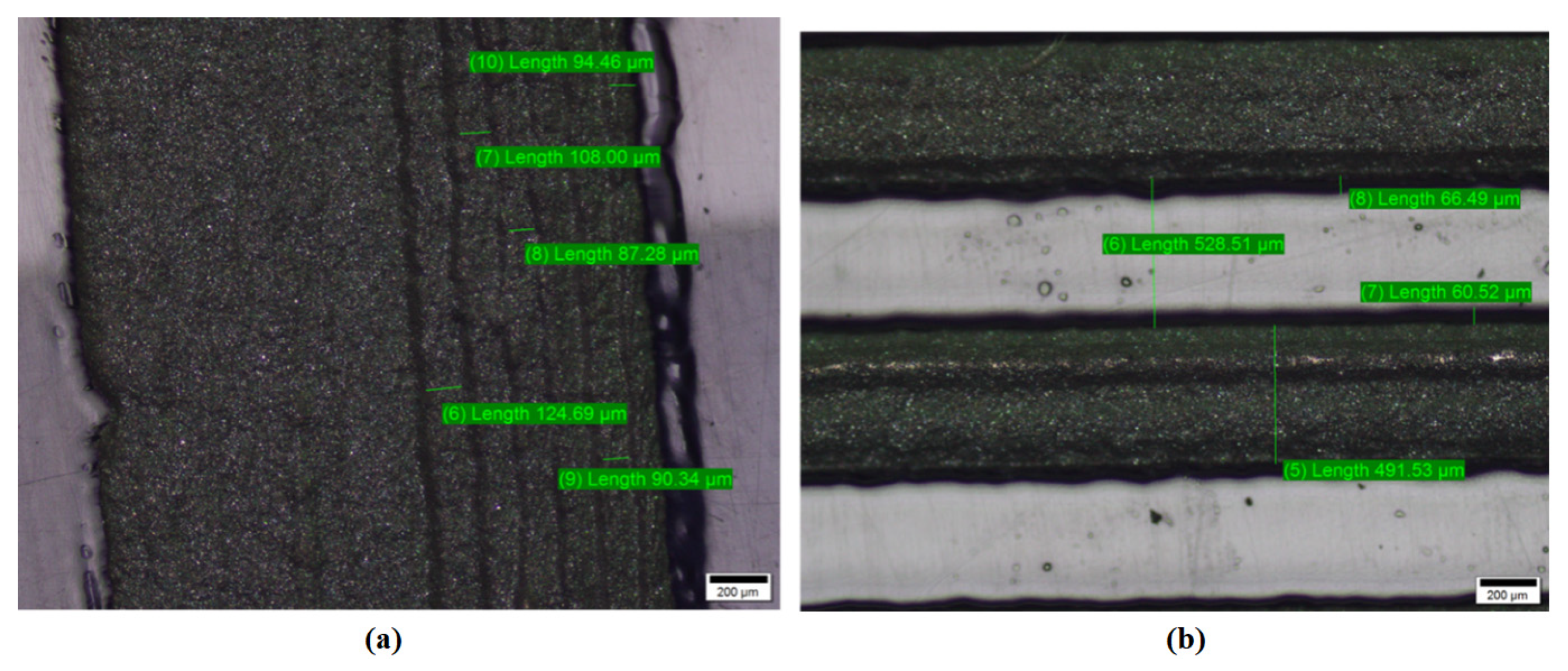
3.2. Evaluation of Pattern Accuracy

The manufactured electrode was evaluated using an Olympus BX51 optical microscope (Olympus, Tokyo, Japan) to verify the pattern accuracy of the electrode profile (OPM). The optical microscope-based surface analysis can be effectively utilized to analyze the performance measures of the system [29,30]. Smooth edges with a random thickness distribution of 0.5mm were detected in the pattern depicted in Figure 8. It was also discovered that the electrode track was printed with a non-uniform distribution over the sheets, and the nozzle path had a mountain and valley sensor formation. The feed movement of the nozzle may also be the result of making valley and mountain dispersion of AgNP, as shown in Figure 9. It was also found that shadow electrodes were distributed over the polymer substrate using 3D IJP. Such marks were not identified with screen printing [22].

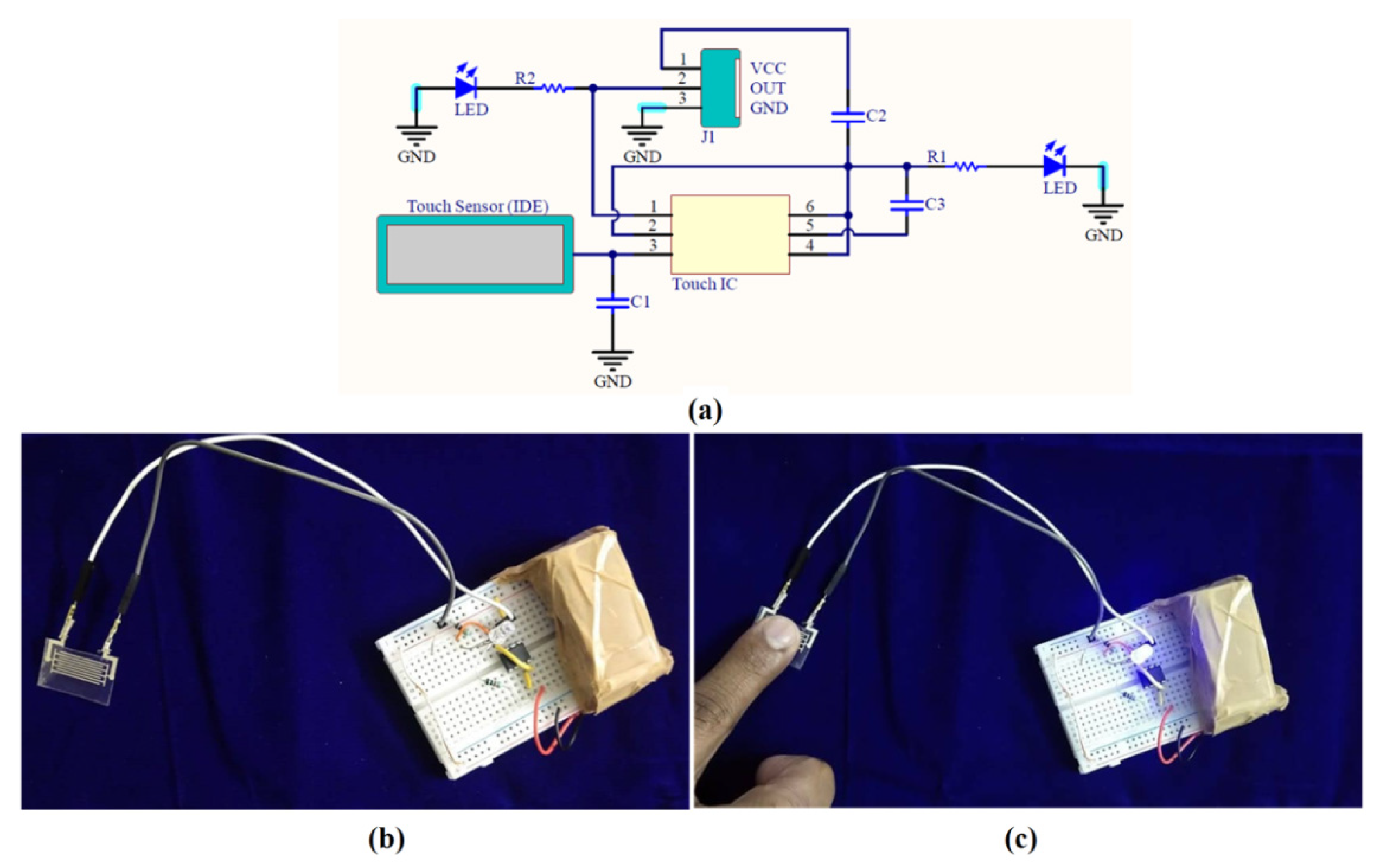
3.3. Sensitivity Comparison of FPS Using Screen Printing and 3D Inkjet Printing Process

The printed FPS was fabricated using conventional screen printing (SP) and proposed 3D inkjet printing (3D IJP) methods. An investigation was prepared to find the optimal overlap distance (OL), electrode line width (EW), and electrode gap (EG) for better printed sensing characteristics [22]. The Taguchi methodology was used to design the experimental trials to be conducted for the experimental analysis in the present study. The number of trial specimens was selected as nine, since the experiment involved two input factors, such as OL (5 mm, 10 mm, 15 mm), EW (0.5 mm, 0.8 mm, 1.2 mm), and EG (0.5 mm, 0.8 mm, 1.2 mm), along with three different levels. In order to improve the measurement accuracy, all trials were carried out three times. The average of those three values was used as the final value. The Keysight U1733C 20,000 Count Handheld LCR Meter with dual display was used for measuring sensitivity using change in capacitance (ΔC) during touch, and it can be denoted in terms of pico farads (pF). Table 1 shows the sensitivity of FPS using screen printing and 3D inkjet printing. It was observed that screen printing could create higher sensitivity-based FPS. The smaller standard error indicated the higher accuracy of sensitivity measurement, as shown in Figure 10. The interdigitated design with overlap (15 mm), electrode width (0.8 mm), and electrode gap (0.5 mm) produces higher sensitivity under both processes. Since the higher overlap region creates a larger area of capacitance, the electric field intensity is considerably changed, owing to the spatial interpolation during the touch. Thus, the overlap possesses a more influent nature on evaluating the sensitivity of flexible printer capacitive sensors. The interdigitated design with overlap (5 mm), electrode width (1.2 mm), and electrode gap (1.2 mm) results in a lower change, due to the smaller overlap region.
The response characteristics were determined to include the capacitance change (C) during touch (pF) in order to quantify the capacitance change. Similarly, the Keysight U1733C 20,000 Count Handheld LCR Meter with dual display was used. The experimental trials with performance measures in this investigation were created according to the design described in Table 1. It was observed that screen printing could produce higher ΔC values as compared with the 3D IJP method, owing to its uniform distribution and defect-free environment. Both methods can produce the FPS to meet the automotive standard specifications. The average thickness of the FPS was observed as 13 microns with the SP methodology and 47 microns with the 3D IJP method. Whenever larger mass production was needed, the SP method could be utilized, owing to the larger investment cost and fixed pattern. Nevertheless, if smaller production with variable patterns were needed, the 3D IJP method can be utilized.

4. Conclusions

This paper provides insights about the different HMI types in automotive audio system and its different fabrication methods, such as 3D IJP and SP. The paper analyzes and summarizes factors that influence electrode design to achieve better performance of the HMI, as follows: interdigitated sensor pattern on polycarbonate sheet in both fabrication processes shows touch performance. However, the interdigitated design with overlap (15 mm), electrode width (0.8 mm), and electrode gap (0.5 mm) results in a higher change. The inkjet process can be used for initial prototype and design verification in the product development process to gain confidence in the design. The screen printing process can be used for high mass production and consistent quality throughput with low cost. The screen printing process needs some initial time and investment for set-up, whereas inkjet printing does not require any.

Author Contributions

Conceptualization, S.P. and M.T.; methodology, S.P., K.M., M.T. and A.M.A.-A.; software, M.T.; validation, M.T., A.M.A.-A. and S.P.; formal analysis, K.M. and S.P.; investigation, M.T., A.M.A.-A. and K.M.; resources, S.P.; writing—original draft preparation, M.T., A.M.A.-A. and K.M.; project administration, M.T. and S.P.; funding acquisition, K.M., A.M.A.-A. and S.P. All authors have read and agreed to the published version of the manuscript.

Funding

This study received funding from the Raytheon Chair for Systems Engineering.

Institutional Review Board Statement

Not applicable.

Informed Consent Statement

Not applicable.

Data Availability Statement

The data presented in this study are available from the corresponding author on reasonable request.

Acknowledgments

The authors are grateful to the Raytheon Chair for Systems Engineering for funding.

Conflicts of Interest

The authors declare no conflict of interest.

References

  1. Khan, S.; Lorenzelli, L.; Dahiya, R.S. Technologies for printing sensors and electronics over large flexible substrates: A review. IEEE Sens. J. 2015, 15, 3164–3185. [Google Scholar] [CrossRef]
  2. Muthuramalingam, T.; Rabik, M.M.; Saravanakumar, D.; Jaswanth, K. Sensor integration based approach for automatic fork lift trucks. IEEE Sens. J. 2018, 18, 736–740. [Google Scholar] [CrossRef]
  3. Rabik, M.M.; Muthuramalingam, T. Tracking and locking system for shooter with sensory noise cancellation. IEEE Sens. J. 2018, 18, 732–735. [Google Scholar] [CrossRef]
  4. Chang, W.Y.; Fang, T.H.; Lin, H.J.; Shen, Y.T.; Lin, Y.C. A large area flexible array sensors using screen printing technology. J. Display Technol. 2009, 5, 178–183. [Google Scholar] [CrossRef]
  5. Choi, M.C.; Kim, Y.; Ha, C.S. Polymers for flexible displays: From material selection to device applications. Prog. Polym. Sci. 2008, 33, 581–630. [Google Scholar] [CrossRef]
  6. Srinivasan, K.P.; Muthuramalingam, T. In-depth scrutinization of in-mold electronics for automotive applications. J. Phys. Conf. Ser. 2021, 1969, 012064. [Google Scholar] [CrossRef]
  7. Gong, Y.; Cha, K.J.; Park, J.M. Deformation characteristics and resistance distribution in thermoforming of printed electrical circuits for in-mold electronics application. Int. J. Adv. Manuf. Technol. 2020, 108, 749–758. [Google Scholar] [CrossRef]
  8. Rao, R.V.K.; Abhinav, K.V.; Karthik, P.S.; Singh, S.P. Conductive silver inks and their applications in printed and flexible electronics. RSC Adv. 2015, 5, 77760–77790. [Google Scholar]
  9. Albrecht, A.; Trautmann, M.; Becherer, M.; Lugli, P.; Rivadeneyra, A. Shear-force sensors on flexible substrates using inkjet printing. J. Sens. 2019, 2019, 1864239. [Google Scholar] [CrossRef] [Green Version]
  10. Gaspar, C.; Olkkonen, J.; Passoja, S.; Smolander, M. Paper as active layer in inkjet-printed capacitive humidity sensors. Sensors 2017, 17, 1464. [Google Scholar] [CrossRef] [Green Version]
  11. Tobjörk, D.; Österbacka, R. Paper electronics. Adv. Mater. 2011, 23, 1935–1961. [Google Scholar] [CrossRef] [PubMed]
  12. Srinivasan, K.P.; Muthuramalingam, T. Design, fabrication, and crack analysis of silver track printed flexible sensor for automobile infotainment application. IEEE Sens. J. 2021, 21, 13910–13915. [Google Scholar] [CrossRef]
  13. Duan, D.L.; Li, S.; Zhang, R.L.; Hu, W.Y.; Li, S.Z. Evaluation of adhesion between coating and substrate by a single pendulum impact scratch test. Thin Solid Films 2006, 515, 2244–2250. [Google Scholar] [CrossRef]
  14. Lopez, F.M.; Briand, D.; Rooij, N.F.D. All additive inkjet printed humidity sensors on plastic substrate. Sens. Actuators B Chem. 2012, 166–167, 212–222. [Google Scholar] [CrossRef]
  15. Igreja, R.; Dias, C.J. Analytical evaluation of the interdigital electrodes capacitance for a multi-layered structure. Sens. Actuators A Phys. 2004, 112, 291–301. [Google Scholar] [CrossRef]
  16. Feng, F.; Liu, Y.; Chen, Y. Effects of quantity and size of buttons of in-vehicle touch screen on drivers’ eye glance behavior. Int. J. Hum. Comput. Interact. 2018, 34, 1105–1118. [Google Scholar] [CrossRef]
  17. Suikkola, J.; Jörninen, T.; Mosallaei, M.; Kankkunen, T.; Ketola, P.I.; Ukkonen, L.; Vanhala, J.; Mäntysalo, M. Screen-printing fabrication and characterization of stretchable electronics. Sci. Rep. 2016, 6, 25784. [Google Scholar] [CrossRef]
  18. Mieghem, B.V.; Desplentere, F.; Bael, A.V.; Ivens, J. Improvements in thermoforming simulation by use of 3D digital image correlation. Exp. Polym. Lett. 2015, 9, 119–128. [Google Scholar] [CrossRef]
  19. Ali, S.M.; Sovuthy, C.; Imran, M.A.; Socheatra, S.; Abbasi, Q.H.; Abidin, Z.Z. Recent advances of wearable antennas in materials, fabrication methods, designs, and their applications: State-of-the-art. Micromachines 2020, 11, 888. [Google Scholar] [CrossRef]
  20. Cao, R.; Pu, X.; Du, X.; Yang, W.; Wang, J.; Guo, H.; Zhao, S.; Yuan, Z.; Zhang, C.; Li, C.; et al. Screen-printed washable electronic textiles as self-powered touch/gesture tribo-sensors for intelligent human–machine interaction. ACS Nano 2018, 12, 5190–5196. [Google Scholar] [CrossRef]
  21. Huang, Q.; Zhu, Y. Printing conductive nanomaterials for flexible and stretchable electronics: A review of materials, processes, and applications. Adv. Mater. Technol. 2019, 4, 1800546. [Google Scholar] [CrossRef]
  22. Srinivasan, K.P.; Muthuramalingam, T. Fabrication and performance evolution of AgNP interdigitated electrode touch sensor for automotive infotainment. Sensors 2021, 21, 7961. [Google Scholar] [CrossRef] [PubMed]
  23. Zhuldybina, M.; Ropagnol, X.; Bois, C.; Zednik, R.J.; Blanchard, F. Printing accuracy tracking with 2D optical microscopy and super-resolution meta material-assisted 1D terahertz spectroscopy. Npj Flex. Electron. 2020, 4, 21. [Google Scholar] [CrossRef]
  24. Li, W.; Yang, S.; Shamim, A. Screen printing of silver nanowires: Balancing conductivity with transparency while maintaining flexibility and stretchability. Npj Flex. Electron. 2019, 3, 13. [Google Scholar] [CrossRef]
  25. Manjunath, G.; Pujar, P.; Gupta, B.; Gupta, D.; Mandal, S. Low-temperature reducible particle-free screen-printable silver ink for the fabrication of high conductive electrodes. J. Mater. Sci. Mater. Electron. 2019, 30, 18647–18658. [Google Scholar] [CrossRef]
  26. Zhong, T.; Jin, N.; Yuan, W.; Zhou, C.; Gu, W.; Cui, Z. Printable stretchable silver ink and application to printed RFID tags for wearable electronics. Materials 2019, 12, 3036. [Google Scholar] [CrossRef] [Green Version]
  27. Muthuramalingam, T. Measuring the influence of discharge energy on white layer thickness in electrical discharge machining process. Measurement 2019, 131, 694–700. [Google Scholar] [CrossRef]
  28. Muthuramalingam, T.; Mohan, B. Design and fabrication of control system based iso current pulse generator for electrical discharge machining. Int. J. Mechatron. Manuf. Syst. 2013, 6, 133–143. [Google Scholar]
  29. Muthuramalingam, T.; Akash, R.; Krishnan, S.; Phan, N.H.; Pi, V.N.; Elsheikh, A.H. Surface quality measures analysis and optimization on machining titanium alloy using CO2 based Laser beam drilling process. J. Manuf. Process. 2021, 62, 1–6. [Google Scholar] [CrossRef]
  30. Thangaraj, M.; Ramamurthy, A.; Sridharan, K.; Ashwin, S. Analysis of surface performance measures on WEDM processed titanium alloy with coated electrodes. Mater. Res. Express 2018, 5, 126503. [Google Scholar]
Figure 1. Schematic representation of audio system: (a) bezel assembly; (b) HMI through keypad; (c) HMI through tactile switch.
Coatings 12 00416 g001
Figure 2. HMI through flexible capacitive sensor with block diagram.
Coatings 12 00416 g002
Figure 3. Design of IDE Design (a) Single IDE (b) Set of 9 IDE with various OLD and ELW.
Coatings 12 00416 g003
Figure 4. Work Flow for Inkjet Printing.
Coatings 12 00416 g004
Figure 5. Fabrication of FPS using 3D inkjet printing machine: (a) processing of FPS; (b) fabricated FPS.
Coatings 12 00416 g005
Figure 6. (a) Coating measurement using Bruker non-contact profiler; (b) fabricated FPS.
Coatings 12 00416 g006
Figure 7. Verification of bezel: (a) circuit diagram; (b) LED “OFF”; (c) sensor with LED “ON”.
Coatings 12 00416 g007
Figure 8. Characterization using optical microscope: (a) nozzle path; (b) sensor formation—0.5 mm electrode profile.
Coatings 12 00416 g008
Figure 9. Characterization using optical microscope: (a) valley and mountain formation; (b) shadow electrodes.
Coatings 12 00416 g009
Figure 10. Comparison of sensitivity in FPS using 3D IJP and SP.
Coatings 12 00416 g010
Table 1. Sensitivity of FPS with inkjet printing process.
RunOverlap (OL)Electrode Width (EW)Electrode Gap (EG)Sensitivity (pF)
Screen Printing3D Inkjet Printing
Trial 1Trial 2Trial 3Average
150.50.55.302.892.622.022.51
250.80.84.791.712.812.512.34
351.21.24.591.51.732.361.86
4100.50.87.313.542.982.32.94
5100.81.25.773.612.492.612.90
6101.20.55.403.42.32.952.88
7150.51.27.563.322.563.293.05
8150.80.59.173.474.212.923.48
9151.20.88.263.313.172.63.08
Publisher’s Note: MDPI stays neutral with regard to jurisdictional claims in published maps and institutional affiliations.

