Article

Evolution of WSe2 Flakes Synthesized by Thermally Assisted Conversion Method

1
Institute of Optical Materials and Technologies, Bulgarian Academy of Sciences, Acad. G. Bonchev St. 109, 1113 Sofia, Bulgaria
2
Institute of Solid State Physics, Bulgarian Academy of Sciences, 72 Tzarigradsko Chaussee, 1784 Sofia, Bulgaria
3
Faculty of Chemistry and Pharmacy, Sofia University, 1 James Bourchier Blvd., 1164 Sofia, Bulgaria
4
Central Laboratory of Solar Energy and New Energy Sources, Bulgarian Academy of Sciences, 72 Tzarigradsko Chaussee, 1784 Sofia, Bulgaria
5
Institute of General and Inorganic Chemistry, Bulgarian Academy of Sciences, Akad. G. Bonchev St., Bl. 11, 1113 Sofia, Bulgaria
*
Author to whom correspondence should be addressed.
Coatings 2022, 12(3), 353; https://doi.org/10.3390/coatings12030353
Submission received: 17 January 2022 / Revised: 27 February 2022 / Accepted: 28 February 2022 / Published: 7 March 2022
(This article belongs to the Special Issue Application of Graphene and Two-Dimensional Materials in Thin Films)

Abstract

:
We report the synthesis of tungsten diselenide (WSe2) flakes and continuous layers using an atmospheric pressure thermally assisted conversion (TAC) method, where the tungsten (W) layers were pre-deposited by a magnetron sputtering system onto fused silica substrates. Optical microscopy (OM) and atomic force microscopy (AFM) mapping predominantly revealed the formation of isolated flakes with different shapes, mainly concentrated near the substrate’s edges, which tended to form clusters and to further overlap to continuous layers, moving to the central part of the fused silica substrates. Raman spectroscopy and photoluminescence measurements confirmed the existence of atomically thin flakes and 2H-WSe2 continuous layers. The measured current–voltage characteristics indicated Ohmic behavior under dark conditions and photo illumination. Finally, the demonstrated resistor-like behavior suggested unlimited prospects for WSe2 integration into a variety of heterostructures.

1. Introduction

Transition metal dichalcogenides (TMDCs) are a large class of inorganic layered materials composed of transition metals (such as molybdenum, tungsten, niobium, etc.) sandwiched between two layers of chalcogen (sulfur, selenium or tellurium) atoms. The strong in-plane covalent bonds and weak van der Waals bonds joining adjacent layers determine the extraordinary electron mobility, capability to tune the bandgap via layer numbers and extremely strong anisotropy, which open great potential for post silicon industry and optoelectronic engineering, e.g., developing of field effect transistors, energy storage devices, and highly efficient solar cells [1,2,3,4,5].
There are several well-developed techniques that have proved to be successful for TMDC s production [6,7]. Among the most frequently used methods are: mechanical exfoliation [8] (the simplest top-down method; however, it is time-consuming and has a large drawback of limited flake size); the chemical vapor deposition (CVD) method [9,10,11,12] (the bottom-up approach, considered as the optimal growth method for crystalline monolayers and large-area synthesis; however, it requires a high temperature process, which challenges the thermal stability and limits the choice of substrates); and the molecular beam epitaxy (MBE) method [13] (another bottom-up approach that allows high purity and growth control, but that also has low throughput). The synthesis methods discussed so far suffer from drawbacks, either in scalability, quality, or control of growth. In order to address some of these issues and to accomplish the potential of TMDC’s materials, a synthesis route that is controlled, scalable, and reproducible is required. A further prerequisite is the ability of the materials to be integrated with semiconductor industry process flows. Thermally assisted conversion (TAC), a variant of CVD, shows promise for meeting these requirements. The TAC method [14] uses a pre-deposited metal layer and allows the metal to be converted into a transition metal dichalcogenide by insertion into a vapor phase chalcogen. Usually, the TAC method results in poly-crystalline material and has several advantages over other methods, such as precise thickness control (control over the number of layers) on large areas. The intrinsic drawbacks of the TAC method include the formation of polycrystalline films and the difficulty of controlling the introduction of dopants. Furthermore, the monolayer synthesis is rather complicated.
Among TMDC materials such as MoS2, MoSe2 and WS2 (which are n-type semiconductors), WSe2 is a semiconducting material in both bulk and monolayer form, which intrinsically features p-type charge carriers’ mobility [6,7]. While the bulk WSe2 possesses an indirect band gap of 1.2 eV, with the layer’s number decreasing, it gradually turns to a direct band gap of 1.65 eV in monolayer form [12]. WSe2 showed very high absorption in the visible to infrared spectral range, resulting in efficient photoluminescence (PL) as well as high charge-carrier mobilities. As for the synthesis of WSe2, large-size flakes have been realized, but high-quality WSe2 continuous films remain in great demand for various applications. The ability to use TAC to synthesize WSe2 continuous films and to incorporate it into heterostacks is, for instance, a potential route toward atomic scale p-n junctions [15].
Here, we report the synthesis details of WSe2 layers using the TAC method for different pre-deposition times of the W layer on fused silica, followed by detailed characterizations, particularly of flakes morphologies. The mapping of WSe2 shapes using optical microscopy and atomic force microscopy revealed the formation of triangular, dendritic and hexagonal-like shapes near the edges of the substrate. Next, the presence of monolayer and few-layer flakes and continuous polycrystalline films was confirmed by Raman and fluorescence analysis. In the final section, Ohmic behavior and dark/photocurrent characteristics are presented, proving further opportunity for opto-electrical applications.

2. Materials and Methods

In our experiments, WSe2 films were synthesized by the thermal assisted conversion method in two steps: first, tungsten (W) layers were pre-deposited on fused silica substrates using a custom-made magnetron sputtering system, followed by direct selenization in a chemical vapor deposition CVD reactor (Carbolite Gero Ltd., Sheffield, UK) (consisted of a tube furnace with three independent thermal zones, see Figure 1a) at atmospheric pressure. For the magnetron sputtering, the fused silica substrates were rotated during the sputtering process, where the applied power was set to 300 W and the deposition pressure was fixed to 6 × 10⁻¹ torr for three different deposition times of W- 3, 5 and 8 s, respectively.
Next, downstream to the Se vapor source from Se powder in CVD quartz tube reactor, the pre-deposited W film on fused silica substrates were placed on a quartz holder. The CVD reactor was under 150 sccm Ar/H2 mixture (90% Ar/10% H2) gas flow during the synthesis process. The temperature of the first zone (Se powder) was raised to 280 °C, whereas the second zone was set to 660 °C and the third one (an empty zone) was set to ~680 °C (in order to keep the temperature of the second zone stable). When the experimental conditions were achieved, the selenization of tungsten was completed for almost 2 h (photographs of WSe2 layers are shown at Figure 1b).
The detailed morphology of the synthesized WSe2 layers was analyzed with an Olympus BX53M optical microscope (Olympus Corporation, Tokyo, Japan) equipped with a DP23 color camera (Olympus Corporation, Tokyo, Japan). The surface and corresponding height profile of WSe2 flakes were measured by an atomic force microscope (AFM), MFP-3D Asylum Research, Oxford Instruments, Abingdon, UK).
The Raman spectra were measured in backscattering geometry in the range of 150–500 cm−1 in a HORIBA Jobin Yvon Labram HR visible spectrometer (Horiba Ltd., Kyoto, Japan) equipped with a Peltier-cooled CCD detector. The 632.8 nm line of an He-Ne laser was used for the excitation. The laser power was attenuated to 500 µW to avoid sample overheating.
Photoluminescence excitation spectra were recorded with a FluoroLog3-22, Horiba Jobin Yvon spectrofluorometer (Horiba Ltd., Kyoto, Japan) at room temperature, using the angle of incoming light of 60 degrees, slit of 3 nm, integration time 5 s and continuous-wave excitation at 500 nm.
Optical absorbance spectra were measured using a UV-VIS-NIR Spectrophotometer Varian Cary 5E (Agilent (Varian Inc.), Santa Clara, CA, USA). The spectral bandwidth and the scan rate were 1 nm and 140 nm min−1, respectively.
The electrical and photoelectrical measurements were done using a dark/photocurrent electrical diagram set-up. For the light illumination, a diode emitting at 283 nm was used to measure the photocurrent. All measurements were performed using a Keithley 617 electrometer (Tektronix Inc., Beaverton, OR, USA) and a Keithley 230 voltage source (Tektronix, Inc., Beaverton, OR, USA).

3. Results and Discussion

3.1. Optical Microscopy (OM) and Atomic Force Microscopy (AFM) Analysis

In general, TDMCs layers exhibit a wide variety of morphologies that take place under different growth conditions [10]. Moreover, the growth substrates have a large influence on the growth mechanism as well. Hence, the detailed mapping of the layers’ shapes enabled us to obtain essential information related to the growth mechanism.
In our study, the synthesized WSe2 layers were first analyzed by optical microscopy (photographs shown at Figure 2a–c for 3, 5 and 8 s deposition time of W, respectively. We tentatively separated each substrate, moving from the very edge to the center into several different regions (labeled as sections A, B, C, D). While investigating each sample, WSe2 flakes with clear triangular, dendrite and hexagonal-like shapes were detected, mainly concentrated near the substrate edges (Figure 2a–c, A and B sections). Moving to the central part, the WSe2 flakes attempted to overlap (Figure 2a–c, C sections) and, finally, turned into a continuous layer with denser morphology, indicating a polycrystalline nature, as illustrated in (Figure 2a–c, D sections) and confirmed later by Raman analysis. Moreover, the tendency for a smooth transition from flake shapes to continuous layer increased with the deposition time of the W layer (the case of 8 s deposition of W layer, Figure 2c). Sputtering is a line-of-sight deposition technique; deposited W precursor layer thickness/density could be different across the substrate surface, particularly in ultrathin films near or under the percolation threshold, as was the case for samples obtained by 3 and 5 s tungsten sputtering time. Therefore, the density of the synthesized WSe2 resembled the density pattern of the deposited precursor material.
Similar formation and distribution of the triangular and hexagonal-like shapes has been reported previously by [11,12]. Some authors have supposed that the observed morphology from the edges to the central part is a result of the limit of the W source in Se vapor volume flow across the surface, which prevents the formation of a continuous WSe2 layer. Although the melting temperature of W is extremely high (over 3000 °C), the inevitable product that is formed during the processing of WO3−x film (Supplementary Material, Figure S1) possesses much lower evaporation temperature; the selenium diffusion and Se–O exchange are facilitated, which results in the formation of WSe2 flakes with different thickness and size [16,17]. Moreover, it is well known that the structure/morphology of the growth substrate influences the growth mechanism of the synthesized layers [18,19].
To analyze the shapes and the thickness of the synthesized WSe2 flakes, we used AFM analysis, as shown in Figure 3a–c for A, B, C and D sections. The corresponding height profiles are presented as well. The measured flake profiles were from 6 nm to 15 nm, indicating that the layer number of the flakes was about 9 to 20 [20]. The triangle, dendritic and hexagon-like WSe2 flakes had relatively small lateral size in a range of a few μm. The sharp-edged triangles indicate that they were highly crystalline WSe2 flakes, whereas the dendritic and hexagon-like forms attempted to shape with increasing the W deposition time.

3.2. Raman Analysis

Representative Raman spectra of WSe2 flakes with different shapes and of polycrystalline continuous WSe2 films with different W deposition times are shown in Figure 4a,b, respectively. They are dominated by three bands (100–150 cm−1, 220–270 cm−1 and 360–410 cm−1) containing the main characteristic WSe2 peaks. In particular, in the main band around 250 cm−1, several overlapping peaks were well discernible after deconvolution. The broad features at ≈220 and ≈240 cm−1 correspond to phonons from the K and M point in the Brillouin zone, respectively [16,21]; the major contribution to this band comes from 2LA(M)—a second-order mode at ~260 cm−1 due to LA phonons at the M point in the Brillouin zone [22], which exhibits strong layer-number dependence [23,24]. WSe2 had the 2H structure; its first-order phonon spectrum contained the Raman active modes E2g (in-plane vibration of W and Se atoms) and 𝐴1g (associated with the out-of-plane vibration of Se atoms). For WSe2, these modes were at rather similar frequencies but, nevertheless, they could be resolved by deconvolution. Band fitting yielded 2 peaks with markedly smaller linewidths characteristic of first-order phonons [24], at ~248 cm−1 and ~252 cm−1 (see Figure 4c) which we assigned to the E2g and the A1g mode, respectively. Different wavelengths of light produced slightly different Raman spectra for the sample because of differences in resonant vibrational modes excited by the frequency of the laser used. As a result, greater peak differentiation of the E2g/A1g modes was possible using a 633 nm laser rather than a 488 nm laser for excitation.
For multilayered WSe2, the Van der Waals interactions between adjacent layers resulted in the activation of an additional peak around 304 cm−1–310 cm−1 (probably corresponding to a second-order mode or to a B2g mode with vibrational pattern modulating the vertical bond between W and Se atoms) [25]. There were also two other characteristic combination bands: the peak observed at 136 cm−1 was assigned to a A1g(M)-LA(M) and the peak observed at ~375 cm−1 to a E2g(M) + LA(M) combination mode [23]. Due to resonance effects with excitonic origin the second-order features in the Raman spectra were very intense [23,25]. For few-layered WSe2 with a single-digit number of layers, the intensity of the 2LA(M) band increased with the number of layers, which was also the case for the B2g and E2g + LA(M) modes [26]. The same held for the A1g mode, in which few-layered WSe2 evolved into a manifold of A-symmetry modes [25].
In the aggregate, the Raman results revealed few-layered WSe2 for the flakes, while the Raman response of the continuous films revealed where the A1g mode was more weakly pronounced and monolayer WSe2 with the possible presence of very thin few-layered WSe2.

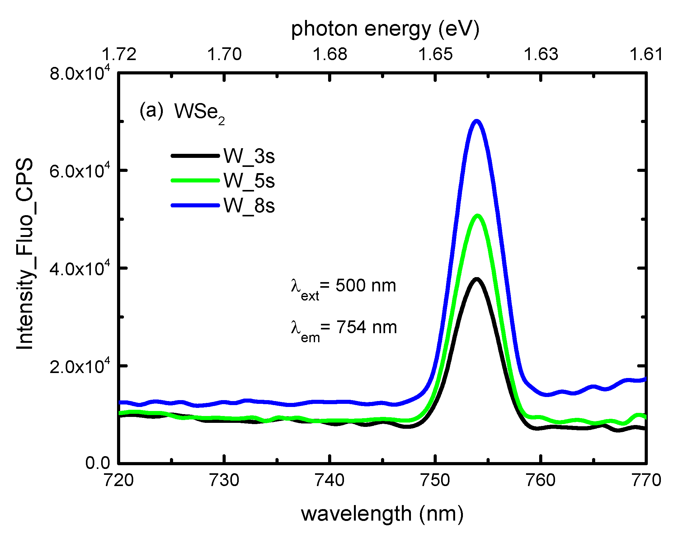
3.3. Photoluminescence and UV-VIS Spectroscopy

Photoluminescence spectroscopy is a direct method used to measure the band gap in TMDs; it plays an essential role in the analysis. We screened the photoluminescence of numerous different flakes in all studied samples. Figure 5 shows a strong photoluminescence signal detected at ~1.64 eV (754 nm), which is in good agreement with the previously reported data (the PL spectrum exhibits a strong direct transition emission at 750–760 nm (752 nm [27,28,29] and 750 nm [30]), due to the direct band gap [31,32]. The peak location is indicative of monolayer nature of both the hexagonal-like and the triangular WSe2 flakes near the substrate edges. Moreover, the PL spectra exhibited a dependance on the time of W-layers deposition. The intensity of photoluminescence emission increased with the increase in the W-layer deposition time (thickness).
WSe2 flakes and layers grown via TAC have strong interactions with the substrate [33]. Fused Silica is the amorphous phase of quartz (SiO2), which lacks the long-range crystalline order. While the optical transmission range and the maximum application temperature were somewhat lower than with crystalline quartz, the shape stability of fused silica was significantly better with the temperature fluctuations due to its very low thermal expansion coefficient. The surface roughness was typically <1 nm. Moreover, fused silica is a good electrical insulator, retaining high resistivity at elevated temperatures and excellent high-frequency characteristics. The substrate material significantly influences the growth mode and properties of WSe2, including the PL signal, for instance, by inducing strain [30]. When the number of WSe2 layers was increased, indirect transitions emissions also appeared at a lower energy. It has been reported that bilayer WSe2 emits at 806 nm with side maximum at 773 nm and, for tri-layer of WSe2, nearly stays at the same position, while the main emission shifts towards a lower energy of 849 nm [34]. In our case no, such emissions were observed, confirming the presence of monolayer flakes, particularly near the substrate’s edges, in all studied samples. In our experiments (using FluoroLog3-22 Spectrofluorometer with 450 W Xe arc lamp light source), the excitation and, respectively, emission area/spot were larger than the area when laser sources were used (i.e., Raman spectrometers). Owing to the sputtering process characteristics and the particular magnetron sputtering system configuration, there were regions around the surface edges where the W coverage was not complete and was clustered, with different lateral size, thickness and spatial/surface distribution. WSe2 was synthesized by the TAC process only at the locations where W clusters existed. With increasing the sputtering time, the number of W clusters increased and distribution became denser. The photoluminescence signal was integrated from a rather larger area than, for example, those using laser sources; therefore, the intensity was enhanced as the number and spatial density of WSe2 monolayer clusters increased.
In addition, an ultraviolet–visible spectroscopy was used to characterize the synthesized WSe2 layers. The measured absorption spectra are shown in Figure 5b. General features of the spectra were in good agreement with previously reported results [16]. According to the literature, the typical excitonic absorption peaks (labeled as A and B at Figure 5b) are located at the wavelengths of 750–775 nm and 625 nm, respectively [5,35]. The excitonic absorption peaks A and B arise from direct gap transitions at the K point. The presence of excitonic transition, red-shifted from the monolayer transition [16,27], demonstrates the few-layer characteristic of the synthesized WSe2 flakes.
As a result of the superpositions of the Se p-orbitals with W d-orbitals, as well as the adjacent layers, the WSe2 spectrum showed further absorption peaks of A’ and B’ [16,35]. The excitonic nature of these peaks could originate from a splitting of the ground and excited states of A and B transitions, respectively, due to inter- and intralayer perturbation to the d electron band by the Se p orbitals [27,36].
The lateral size, and particularly the thickness/layers number, of the flakes were different. The flakes were observed at random preferential locations near the edges of the substrates with pre-deposited W films and growth to different thicknesses, including monolayer flakes, probably due to the selenium diffusion restrictions and local stress influence.

3.4. Electrical and Photo-Electrical Characterization

Finally, we measured the current–voltage (Ids−Vds) characteristics of WSe2 layers, varying source-drain voltage (Vds) from −1 to 1 V at constant gate voltage Vg = 0 V, using Indium (In)-type contacts and the set-up shown at Figure 6a. The linear plot of the drain voltage vs. drain current suggests Ohmic behavior, formed at the source and drain electrodes (see the straight lines at Figure 6b). In addition, the WSe2 layers were illuminated with a diode source emitting at 278 nm (light Intensity of ~0.5 µW/cm2); the difference between the dark current (dash lines) and photocurrent (straight lines) are presented in Figure 6b. The measured dark/photo current values are similar to those reported for WSe2 based photodetectors illuminated with a 633 nm cw laser [33,37,38]. Moreover, the WSe2 sample synthesized for 8 s W layer deposition was evaluated under the light illumination when the DC voltage was fixed at 1 V (on/off cycles are presented at Figure 6c). The measured sample showed a rapid response to the light illumination and a slow recovery in the dark, which could be attributed to the dipole reorientation under the electric field (slower process) and the photoinduced charge carriers in the entire volume (faster process), as well as a possible high number of defects due to WO3. Furthermore, the measurements were performed using a fused silica substrate, TAC synthesis (not high-quality exfoliated samples), and without an encapsulation. All of these factors negatively affected the electrical properties.

4. Conclusions

WSe2 flakes and continuous layers were successfully synthesized by thermally assisted conversion method using controlled selenization of pre-deposited W layers on fused silica substrates. Optical microscopy revealed that WSe2 domains were randomly distributed within the scanned area with predominantly triangular and hexagonal-like shapes, concentrated mainly near the substrate’s edges. The main part of the substrates excluding the edges consisted of continuous WSe2 layers. The Raman analysis yielded evidence for few-layered WSe2, and spectral deconvolution revealed the first-order modes E2g (in-plane vibration) and A1g (out-of-plane vibration) located at ~248 cm−1 and ~252 cm−1, respectively. The ability of TAC method to synthesize WSe2 flakes with controlled size and continuous films opens a potential route for Van der Waals heterostructures for optoelectronic and photonic devices.

Supplementary Materials

The following supporting information can be downloaded at: https://www.mdpi.com/article/10.3390/coatings12030353/s1, Figure S1. Peak-fitted XPS spectra after subtraction of a Shirley background of the W 4f and Se 3d core-levels of WSe2 layer synthesized by TAC method (5 s pre-deposition time of W on Si/SiO2).

Author Contributions

Conceptualization V.M., K.B. and D.D. (Dimitre Dimitrov); methodology V.M., K.B., I.D., N.M., V.V., V.S., H.D., P.R., I.A. and D.D. (Deyan Dimov); software K.B., I.D., V.V., V.S. and P.R.; formal analysis V.M., K.B., V.V., V.S., P.R., I.A. and D.D (Deyan Dimov).; resources V.M. and D.D. (Dimitre Dimitrov); writing—original draft preparation, V.M. and D.D. (Dimitre Dimitrov); writing—review and editing V.M., K.B., P.R. and D.D. (Dimitre Dimitrov), visualization, K.B, I.D., V.S. and V.S.; supervision, V.M. and D.D. (Dimitre Dimitrov); funding acquisition V.M. and D.D. (Dimitre Dimitrov). All authors have read and agreed to the published version of the manuscript.

Funding

This research was funded by Bulgarian Science Fund under the project numbers DFNI КП-06-ДO 02/2 and DFNI КП-06-ДO 02/3 in the frames of M-ERA program project “Functional 2D materials and heterostructures for hybrid spintronic-memristive devices”. V.M. and N.M. acknowledge the financial support by the European Regional Development Fund within the Operational Programme ‘Science and Education for Smart Growth 2014–2020’ under the Project CoE ‘National Center of Mechatronics and Clean Technologies’ BG05M2OP001-1.001-0008-C01. Research equipment of Distributed Research Infrastructure INFRAMAT, part of the Bulgarian National Roadmap for Research Infrastructures, supported by the Bulgarian Ministry of Education and Science was used in these investigations.

Institutional Review Board Statement

Not applicable.

Informed Consent Statement

Not applicable.

Data Availability Statement

Not applicable.

Conflicts of Interest

The authors declare no conflict of interest.

References

  1. Backes, C.; Abdelkader, A.M.; Alonso, C.; Andrieux-Ledier, A.; Arenal, R.; Azpeitia, J.; Balakrishnan, N.; Banszerus, L.; Barjon, J.; Bartali, R.; et al. Production and processing of graphene and related materials. 2D Mater. 2020, 7, 022001. [Google Scholar] [CrossRef]
  2. Manzeli, S.; Ovchinnikov, D.; Pasquier, D.; Yazyev, O.V.; Kis, A. 2D transition metal dichalcogenides. Nat. Rev. Mater. 2017, 2, 17033. [Google Scholar] [CrossRef]
  3. Choi, W.; Choudhary, N.; Han, G.H.; Park, J.; Akinwande, D.; Lee, Y.H. Recent development of two-dimensional transition metal dichalcogenides and their applications. Mater. Today 2017, 20, 116–130. [Google Scholar] [CrossRef]
  4. Xu, S.; Shen, J.; Long, G.; Wu, Z.; Bao, Z.Q.; Liu, C.C.; Xiao, X.; Han, T.; Lin, J.; Wu, Y.; et al. Odd-integer quantum Hall states and giant spin susceptibility in p-type few-layer WSe2. Phys Rev Lett. 2017, 18, 067702. [Google Scholar] [CrossRef] [PubMed] [Green Version]
  5. Boscher, N.D.; Carmalt, C.J.; Parkin, I.P. Atmospheric pressure chemical vapor deposition of WSe2 thin films on glass—Highly hydrophobic sticky surfaces. J. Mater. Chem. 2006, 16, 122–127. [Google Scholar] [CrossRef]
  6. Cheng, Q.; Pang, J.; Sun, D.; Wang, J.; Zhang, S.; Liu, F.; Chen, Y.; Yang, R.; Liang, N.; Lu, X.; et al. WSe2 2D p-type semiconductor-based electronic devices for information technology: Design, preparation, and applications. InfoMat 2020, 2, 656–697. [Google Scholar] [CrossRef]
  7. Briggs, N.; Subramanian, S.; Lin, Z.; Li, X.; Zhang, X.; Zhang, K.; Xiao, K.; Geohegan, D.; Wallace, R.; Chen, L.-Q.; et al. Robinson A Roadmap for Electronic Grade 2-Dimensional Materials. 2D Mater. 2019, 6, 022001. [Google Scholar] [CrossRef]
  8. Liu, F. Mechanical exfoliation of large area 2D materials from vdW crystals. Prog. Surf. Sci. 2021, 96, 100626. [Google Scholar] [CrossRef]
  9. Wong, S.L.; Liu, H.; Chi, D. Recent progress in chemical vapor deposition growth of two-dimensional transitionmetal dichalcogenides. Prog. Cryst. Growth Charact. Mater. 2016, 62, 9–28. [Google Scholar] [CrossRef]
  10. Zhang, J.; Wang, F.; Shenoy, V.B.; Tang, M.; Lou, J. Towards controlled synthesis of 2D crystals by chemical vapor deposition (CVD). Mater. Today 2020, 40, 132–139. [Google Scholar] [CrossRef]
  11. Rajan, A.G.; Warner, J.H.; Blankschtein, D.; Strano, M.S. Generalized Mechanistic Model for the Chemical Vapor Deposition of 2D Transition Metal Dichalcogenide Monolayers. ACS Nano 2016, 10, 4330–4344. [Google Scholar] [CrossRef] [PubMed]
  12. Feng, Q.; Zhu, M.; Zhao, Y.; Liu, H.; Li, M.; Zheng, J.; Xu, H.; Jiang, Y. Chemical vapor deposition growth of sub-centimeter single crystal WSe2 monolayer by NaCl-assistant. Nanotechnology 2019, 30, 034001. [Google Scholar] [CrossRef] [PubMed]
  13. Zhang, Y.; Ugeda, M.M.; Jin, C.; Shi, S.F.; Bradley, A.J.; Recio, A.M.; Ryu, H.; Kim, J.; Tang, S.; Kim, Y.; et al. Electronic Structure, Surface Doping, and Optical Response in Epitaxial WSe2 Thin Films. Nano Lett. 2016, 16, 2485–2491. [Google Scholar] [CrossRef] [PubMed] [Green Version]
  14. Gatensby, R.; McEvoy, N.; Lee, K.; Hallam, T.; Berner, C.N.; Rezvani, E.; Winters, S.; O’Brien, M.; Duesberg, G.S. Controlled synthesis of transition metal dichalcogenide thin films for electronic applications. Appl. Surf. Sci. 2014, 297, 139–146. [Google Scholar] [CrossRef]
  15. Yang, T.; Zheng, B.; Wang, Z.; Xu, T.; Pan, C.; Zou, J.; Zhang, X.; Qi, Z.; Liu, H.; Feng, Y.; et al. Van der Waals epitaxial growth and optoelectronics of large-scale WSe2/SnS2 vertical bilayer p–n junctions. Nat. Commun. 2017, 8, 1906. [Google Scholar] [CrossRef]
  16. Zhao, W.; Ghorannevis, Z.; Chu, L.; Toh, M.; Kloc, C.; Tan, P.H.; Eda, G. Evolution of electronic structure in atomically thin sheets of WS2 and WSe2. ACS Nano 2012, 7, 791–797. [Google Scholar] [CrossRef] [Green Version]
  17. Browning, P.; Eichfeld, S.; Zhang, K.; Hossain, L.; Lin, Y.-C.; Wang, K.; Lu, N.; Waite, A.R.; Voevodin, A.A.; Kim, M.; et al. Large-area synthesis of WSe2 from WO3 by selenium–oxygen ion Exchange. 2D Mater. 2015, 2, 014003. [Google Scholar] [CrossRef]
  18. Wu, D.; Min, T.; Zhou, J.; Li, C.; Ma, G.; Lu, G.; Xia, M.; Gu, Z. Effect of Substrate symmetry on the dendrite morphology of MoS2 Film synthesized by CVD. Sci. Rep. 2017, 7, 15166. [Google Scholar] [CrossRef] [Green Version]
  19. Peters, L.; Coileáin, C.Ó.; Dluzynski, P.; Siris, R.; Duesberg, G.S.; McEvoy, N. Directing the Morphology of Chemical Vapor Deposition-Grown MoS2 on Sapphire by Crystal Plane Selection. Phys. Status Solidi A 2020, 217, 2000073. [Google Scholar] [CrossRef]
  20. Fang, H.; Chuang, S.; Chang, T.C.; Takei, K.; Takahashi, T.; Javey, A. High-Performance Single Layered WSe2 p-FETs with Chemically Doped Contacts. Nano Lett. 2012, 12, 3788–3792. [Google Scholar] [CrossRef] [Green Version]
  21. Wu, P.-C.; Yang, C.-L.; Du, Y.; Lai, C.-H. Scalable Epitaxial Growth of WSe2 Thin Films on SiO2/Si via a Self-Assembled PtSe2 Buffer Layer. Sci. Rep. 2019, 9, 8017. [Google Scholar] [CrossRef] [PubMed]
  22. Nguyen, N.T.; Berseth, P.A.; Lin, Q.; Chiritescu, C.; Cahill, D.G.; Mavrokefalos, A.; Shi, L.; Zschack, P.; Anderson, M.D.; Anderson, I.M.; et al. Synthesis and properties of turbostratically disordered, ultrathin WSe2 films. Chem. Mater. 2010, 22, 2750–2756. [Google Scholar] [CrossRef]
  23. del Corro, E.; Terrones, H.; Elias, A.; Fantini, C.; Feng, S.; Nguyen, M.A.; Mallouk, T.E.; Terrones, M.; Pimenta, M.A. Excited excitonic states in 1L, 2L, 3L, and bulk WSe2 observed by resonant Raman spectroscopy. ACS Nano 2014, 8, 9629–9635. [Google Scholar] [CrossRef] [PubMed]
  24. Zhao, W.; Ghorannevis, Z.; Amara, K.K.; Pang, J.R.; Toh, M.; Zhang, X.; Kloc, C.; Tan, P.H.; Eda, G. Lattice dynamics in mono-and few-layer sheets of WS2 and WSe2. Nanoscale 2013, 5, 9677. [Google Scholar] [CrossRef] [Green Version]
  25. Terrones, H.; Del Corro, E.; Feng, S.; Poumirol, J.M.; Rhodes, D.; Smirnov, D.; Pradhan, N.R.; Lin, Z.; Nguyen, M.A.T.; Elıas, A.L.; et al. New First Order Raman-active Modes in Few Layered Transition Metal Dichalcogenides. Sci. Rep. 2014, 4, 4215. [Google Scholar] [CrossRef]
  26. Sahin, H.; Tongay, S.; Horzum, S.; Fan, W.; Zhou, J.; Li, J.; Wu, J.; Peeters, F.M. Anomalous Raman spectra and thickness-dependent electronic properties of WSe2. Phys. Rev. B 2013, 87, 165409. [Google Scholar] [CrossRef] [Green Version]
  27. Huang, J.-K.; Pu, J.; Hsu, C.-L.; Chiu, M.-H.; Juang, Z.-Y.; Chang, Y.-H.; Chang, W.-H.; Iwasa, Y.; Takenobu, T.; Li, L.-J. Large-area synthesis of highly crystalline WSe2 monolayers and device applications. ACS Nano 2013, 8, 923–930. [Google Scholar] [CrossRef] [Green Version]
  28. Wang, T.; Andrews, K.; Bowman, A.; Hong, T.; Koehler, M.; Yan, J.; Mandrus, D.; Zhou, Z.; Xu, Y.-Q. High-Performance WSe2 Phototransistors with 2D/2D Ohmic Contacts. Nano Lett. 2018, 18, 2766–2771. [Google Scholar] [CrossRef]
  29. Xu, K.; Wang, Z.; Du, X.; Safdal, M.; Jiang, C.; He, J. Atomic-layer triangular WSe2 sheets: Synthesis and layer-dependent photoluminescence property. IOP Nanotechnol. 2013, 24, 465705. [Google Scholar] [CrossRef] [Green Version]
  30. Ahn, G.H.; Amani, M.; Rasool, H.; Lien, D.-H.; Mastandrea, J.P.; Joel, W.A., III; Dubey, M.; Chrzan, D.C.; Minor, A.M.; Javey, A. Strain-engineered growth of two-dimensional materials. Nat. Commun. 2017, 8, 608. [Google Scholar] [CrossRef] [Green Version]
  31. Wilson, J.A.; Yoffe, A.D. The transition metal dichalcogenides discussion and interpretation of the observed optical, electrical and structural properties. Adv. Phys. 1969, 18, 193–335. [Google Scholar] [CrossRef]
  32. Li, Y.; Li, X.; Yu, T.; Yang, G.; Chen, H.; Zhang, C.; Feng, Q.; Ma, J.; Liu, W.; Xu, H.; et al. Accurate identification of layer number for few-layer WS2 and WSe2 via spectroscopic study. Nanotechnology 2018, 29, 124001. [Google Scholar] [CrossRef] [PubMed]
  33. Chen, J.; Liu, B.; Liu, Y.; Tang, W.; Nai, C.T.; Li, L.; Zheng, J.; Gao, L.; Zheng, Y.; Shin, H.S.; et al. Chemical vapor deposition of large sized hexagonal WSe2 crystals on dielectric substrates. Adv. Mater. 2015, 27, 6722–6727. [Google Scholar] [CrossRef] [PubMed]
  34. Tonndorf, P.; Schmidt, R.; Böttger, P.; Zhang, X.; Börner, J.; Liebig, A.; Albrecht, M.; Kloc, C.; Gordan, O.; Zahn, D.R.T. Photoluminescenc emission and Raman response of monolayer MoS2, MoSe2 and WSe2. Opt. Express 2013, 21, 1908–4916. [Google Scholar] [CrossRef] [PubMed]
  35. Sierra-Castillo, A.; Haye, E.; Acosta, S.; Bittencourt, C.; Colomer, J.-F. Synthesis and Characterization of Highly Crystalline Vertically Aligned WSe2 Nanosheets. Appl. Sci. 2020, 10, 874. [Google Scholar] [CrossRef] [Green Version]
  36. Liu, B.; Fathi, M.; Chen, L.; Abbas, A.; Ma, Y.; Zhou, C. Chemical vapor deposition growth of monolayer WSe2 with tunable device characteristics and growth mechanism study. ACS Nano 2015, 9, 6119–6127. [Google Scholar] [CrossRef]
  37. Zhang, W.; Chiu, M.-H.; Chen, C.-H.; Chen, W.; Li, L.-J.; Wee, A.T.S. Role of Metal Contacts in High-Performance Phototransistors Based on WSe2 Monolayers. ACS Nano 2014, 8, 8653–8661. [Google Scholar] [CrossRef] [Green Version]
  38. Zhao, X.; Wang, R.; Guo, S.; Weller, D.; Quan, S.; Yu, J.; Jiang, J.; Wang, Y. Hexagonal WSe2 Nanoplates for Large-Scale Continuous Optoelectronic Films. ACS Appl. Nano Mater. 2021, 4, 5014–5021. [Google Scholar] [CrossRef]
Figure 1. (a) CVD reactor for TAC method and (b) photographs of WSe2 samples on fused silica for 3 s, 5 s and 8 s deposition time of W layers.
Coatings 12 00353 g001
Figure 2. Optical microscope images of WSe2 flakes grown by TAC method (pre-deposited W layer of (a) 3 s; (b) 5 s and (c) 8 s; scale bars 10 µm). Flakes with triangular, dendrite and hexagonal-like shapes are concentrated near the substrate edges (A and B sections). Moving to the center, flakes attempt to overlap (C section) and finally turn to continuous layer with dense morphology; however, for the samples with pre-deposited W layer for 3 and 5 s, still some voids may exist in the places where precursor W was not deposited. (D section).
Coatings 12 00353 g002
Figure 3. AFM images of WSe2 flakes and continuous film for different pre-deposition time of W layers: (a) W 3 s, (b) W 5 s and (c) W 8 s (following vertical direction) at A, B, C and D sectors (A starts from the edge and moving to the center D) (following horizontal rows).
Coatings 12 00353 g003aCoatings 12 00353 g003b
Figure 4. Raman spectra of WSe2 flakes (a) different shapes and (b) polycrystalline WSe2 layers with three different W deposition times as indicated in the plot (c) Deconvolution of the main Raman band between 200 cm−1 and 300 cm−1 of spectrum W 3 s (panel b). The peaks of the Raman active modes A1g (blue) and E2g (red) are plotted with thicker traces.
Coatings 12 00353 g004
Figure 5. (a) Photoluminescence and (b) absorbance spectra of WSe2 layers on fused quartz.
Coatings 12 00353 g005aCoatings 12 00353 g005b
Figure 6. (a) Experimental set-up; (b) photo and dark current of WSe2 layers and (c) on/off cycles WSe2 layer (W layer deposition time of 8 s).
Coatings 12 00353 g006
Publisher’s Note: MDPI stays neutral with regard to jurisdictional claims in published maps and institutional affiliations.

