
Mixed Convection Flow of Magnetized Casson Nanofluid over a Cylindrical Surface

 ,
,  ,
,
Abstract
:1. Introduction
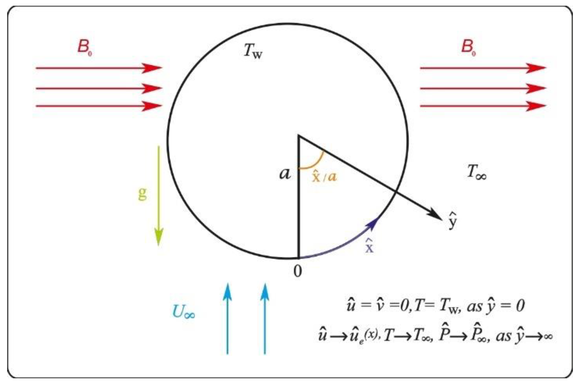
2. Modeling of the Problem
3. Numerical Solution
3.1. The Finite Difference Technique
3.2. Newton’s Method
3.3. The Block Tridiagonal Matrix
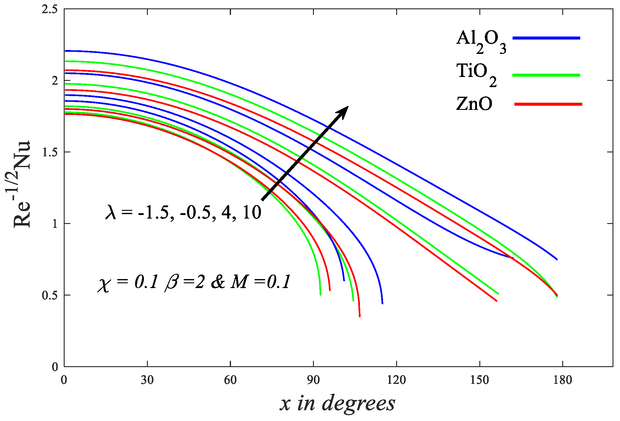
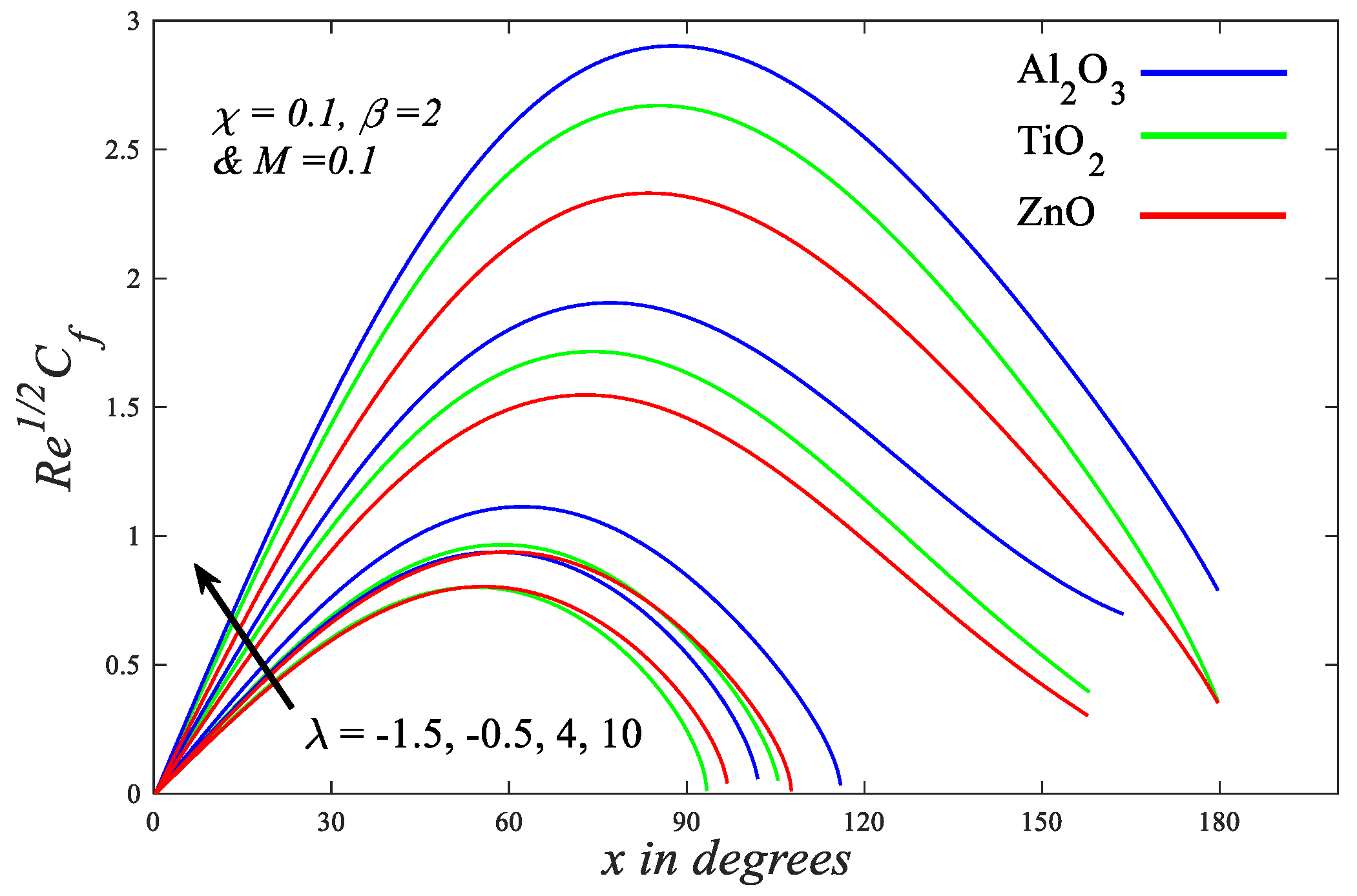
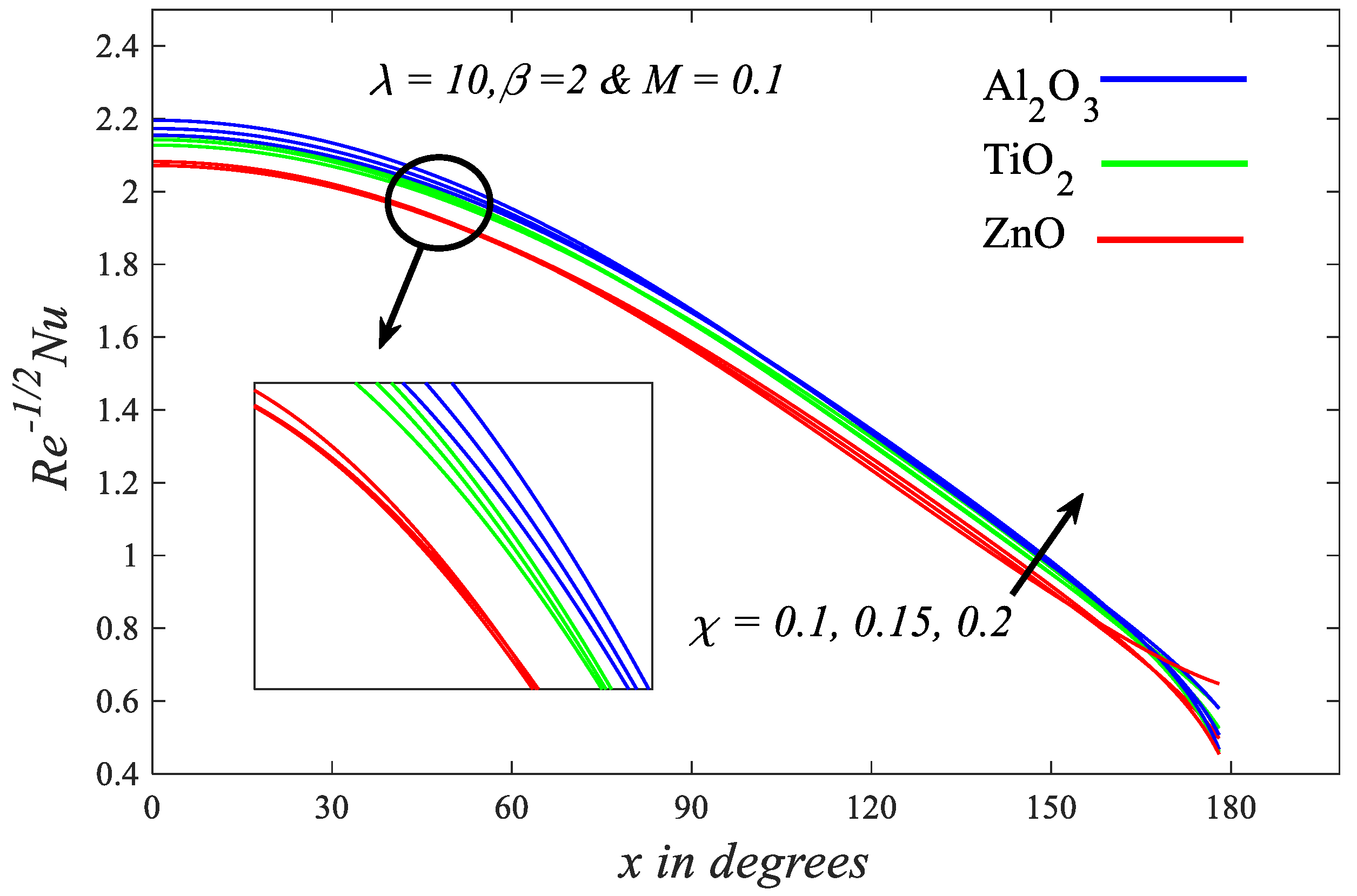
4. Results and Discussion
5. Conclusions
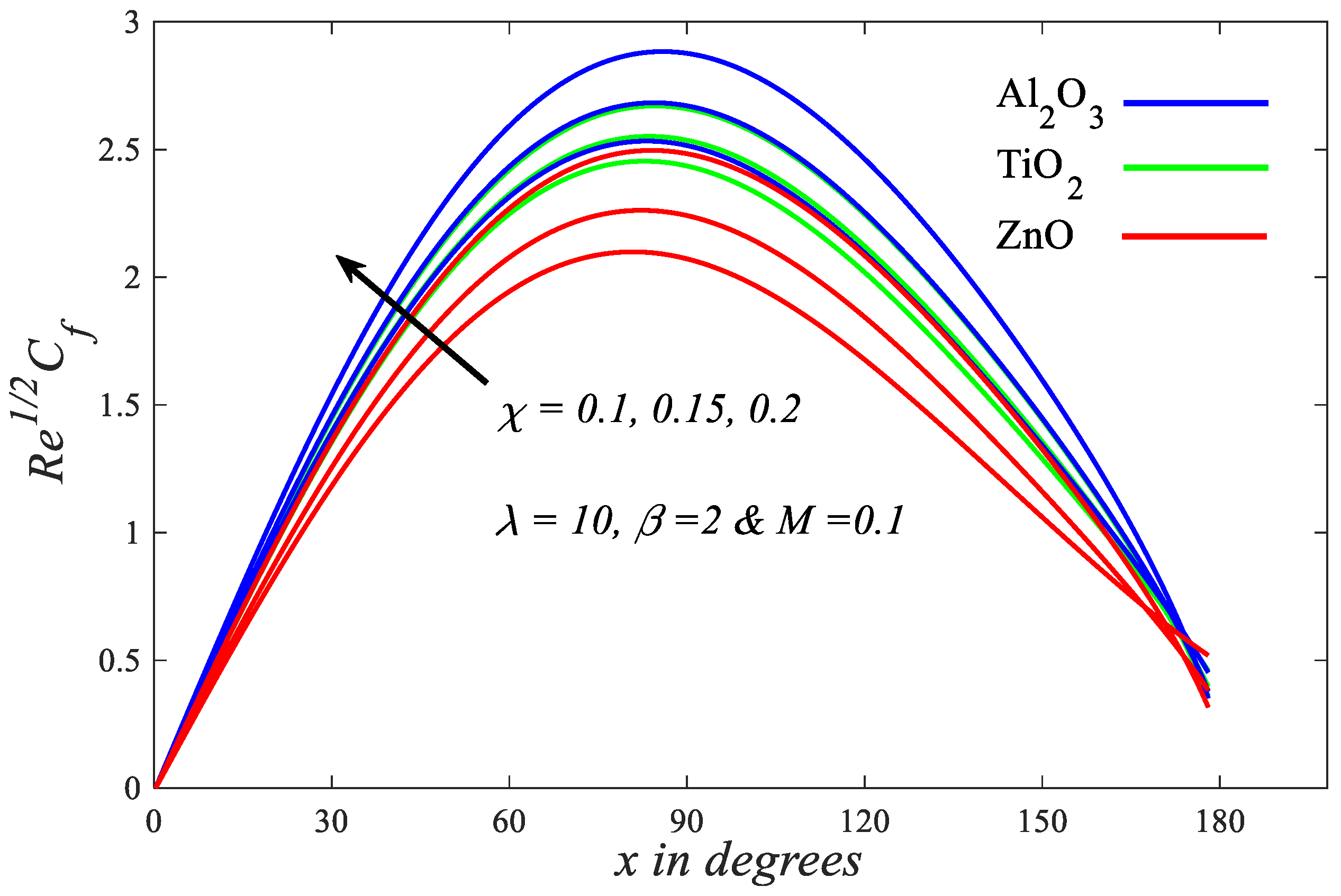
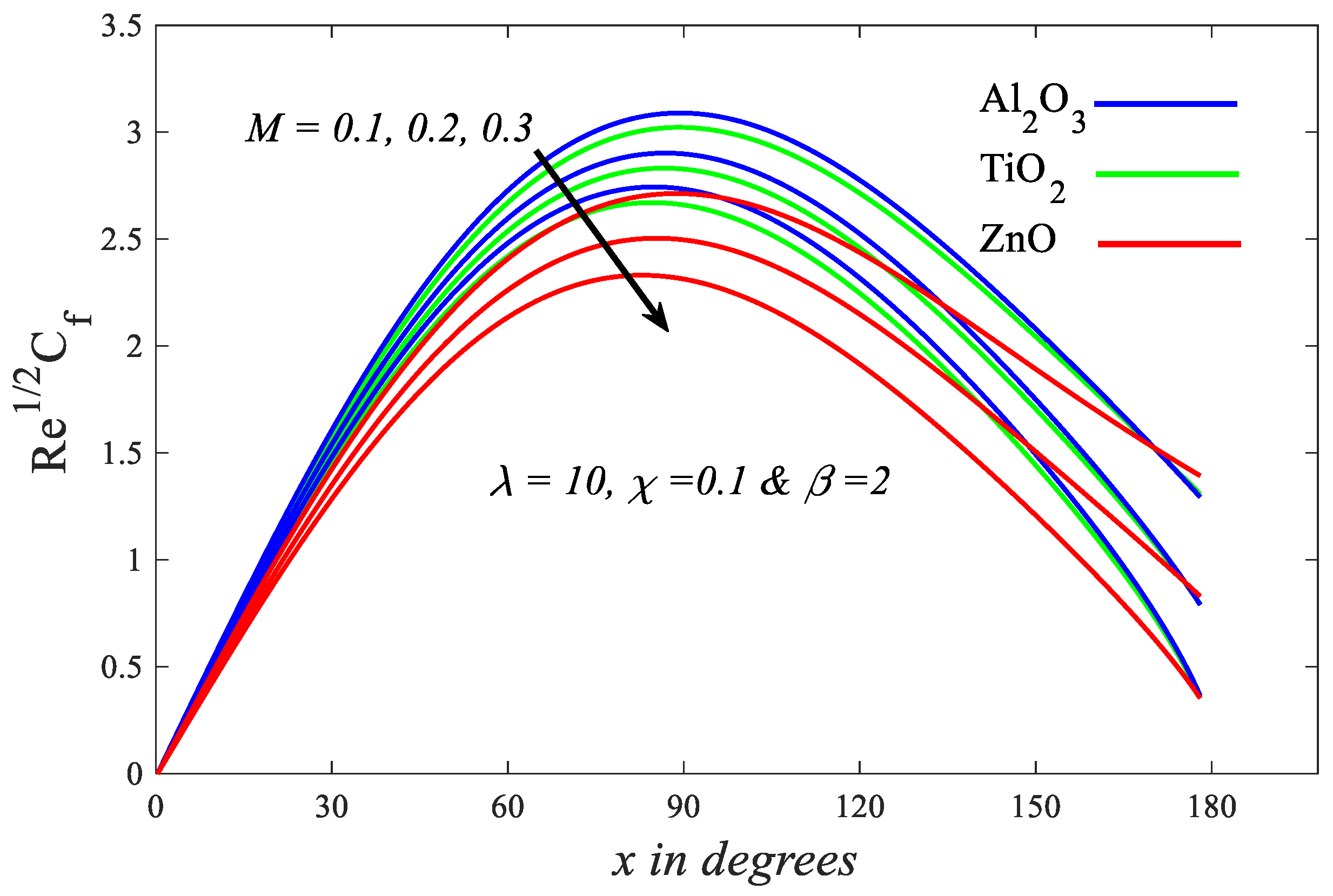
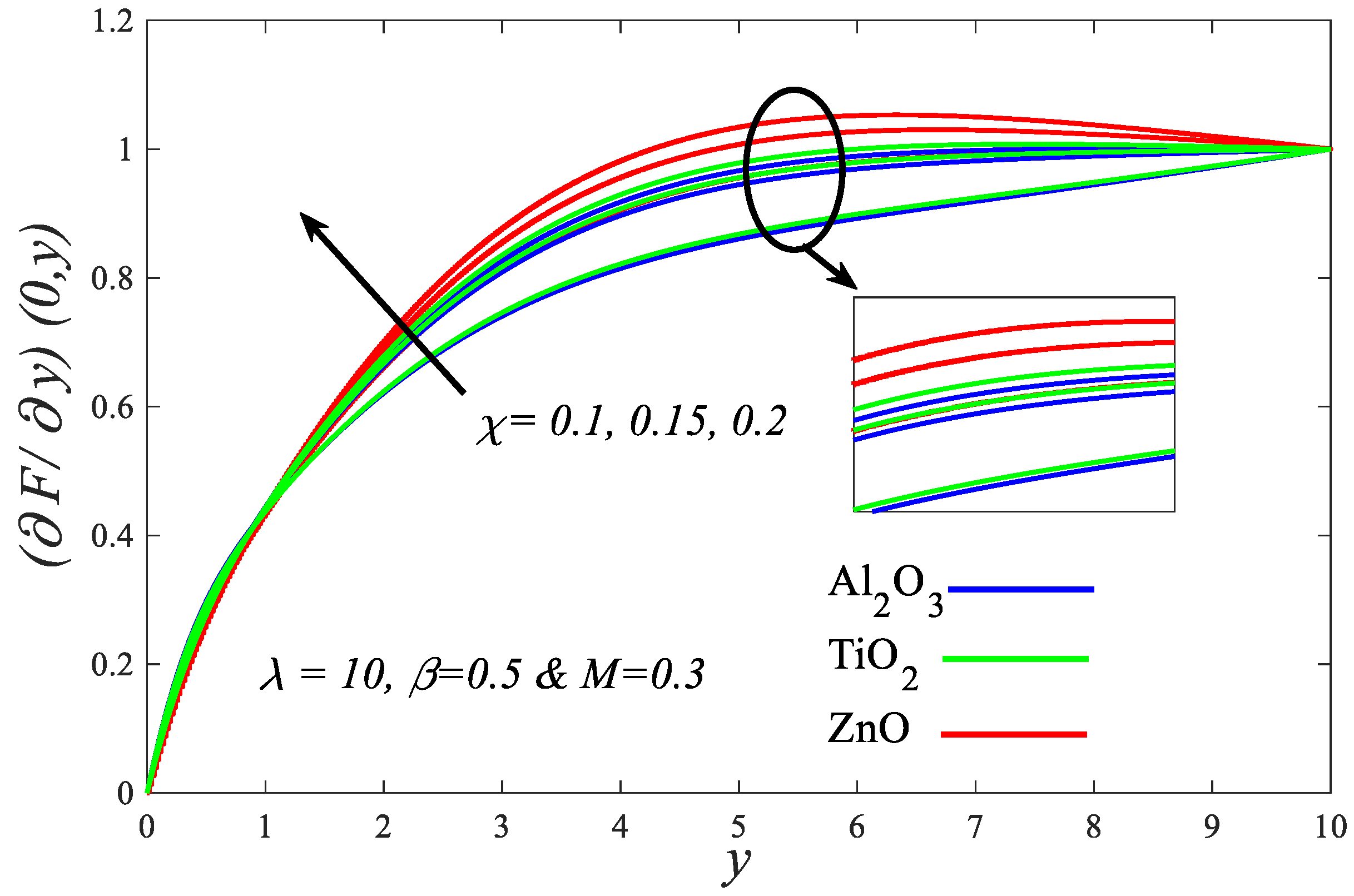
- All the physical quantities studied in this work showed increasing behavior when the values of ultrafine particle volume fraction grew.
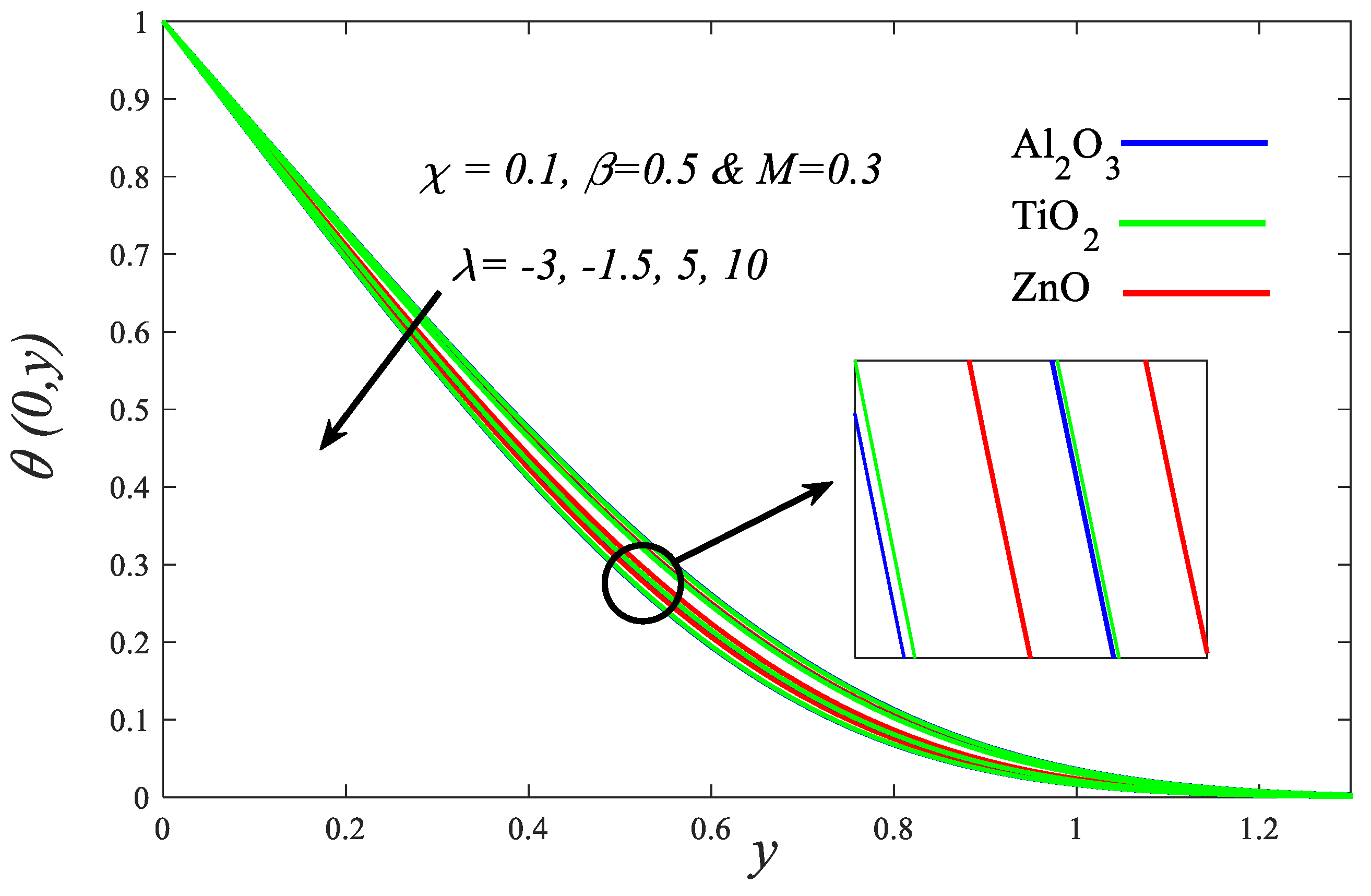
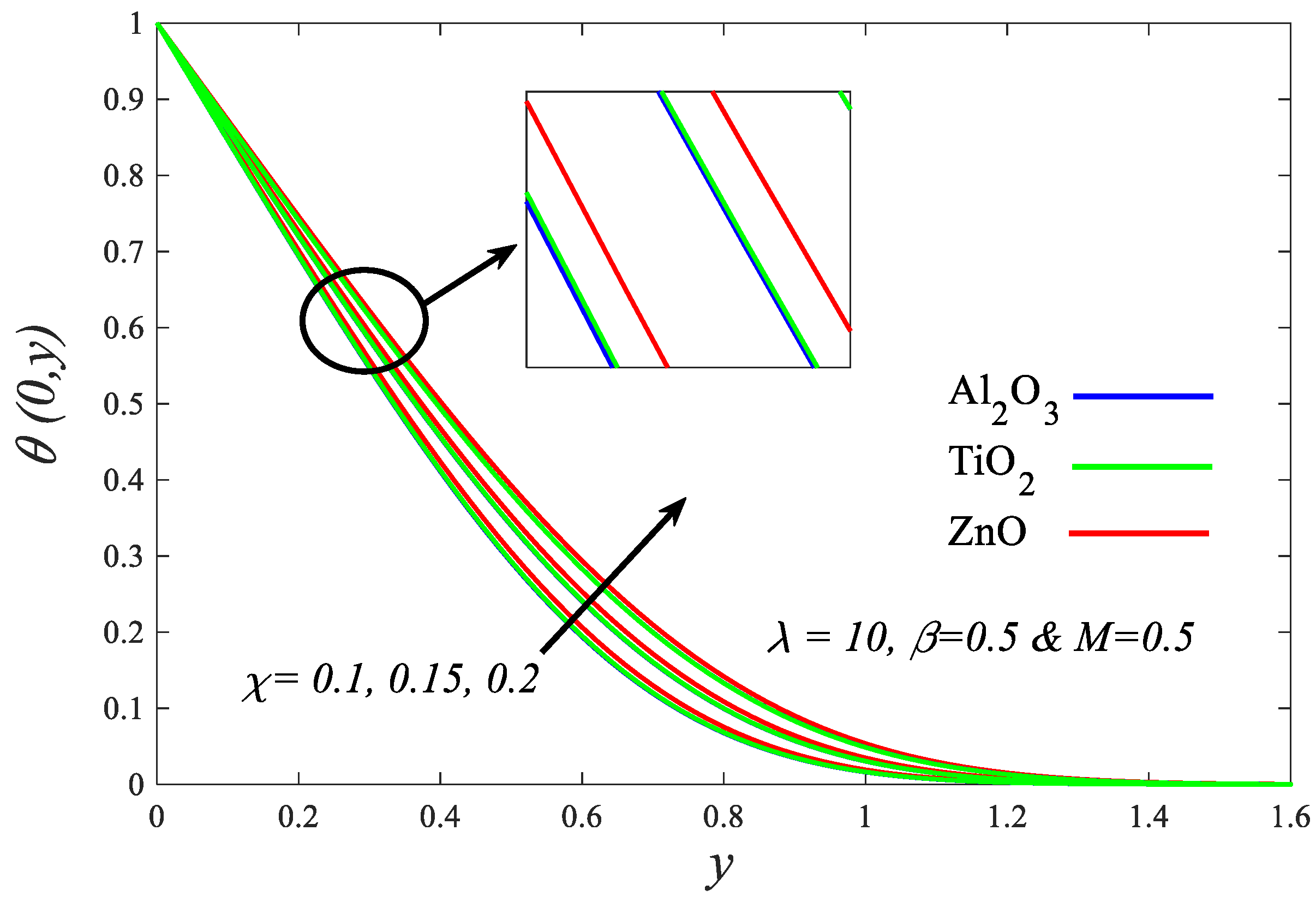
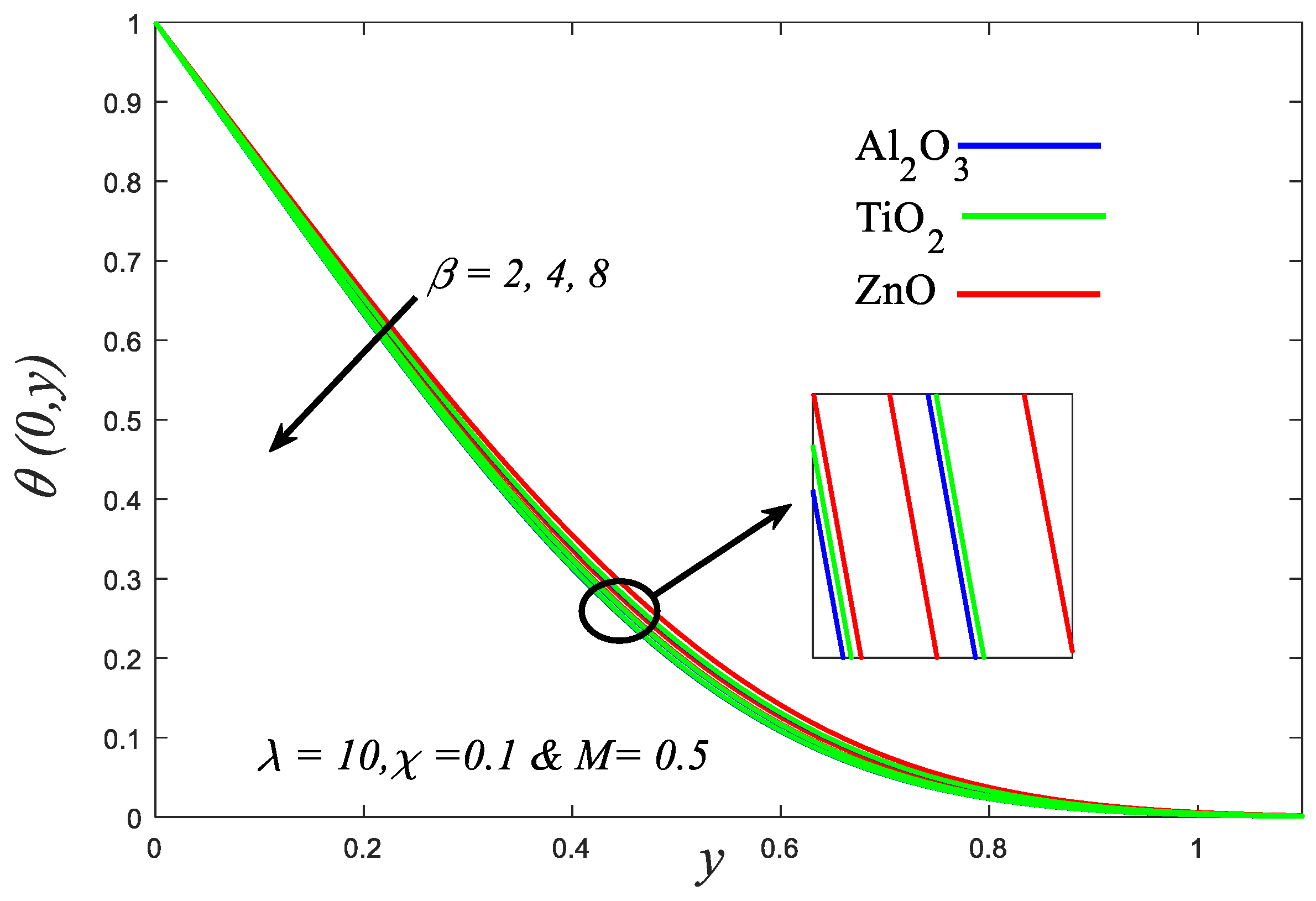
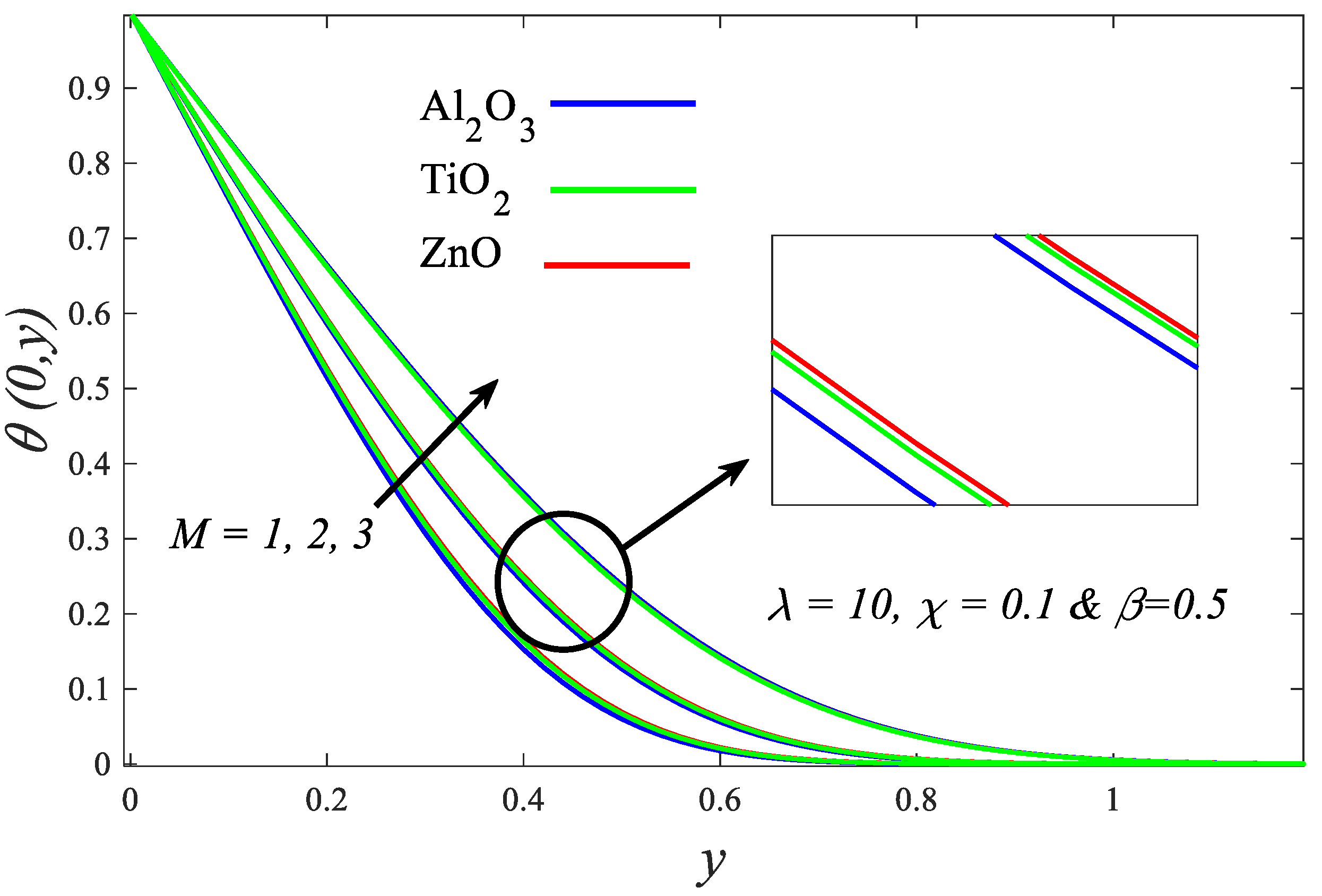
- Temperature possesses an inverse relationship with or , while it has a direct relationship with .
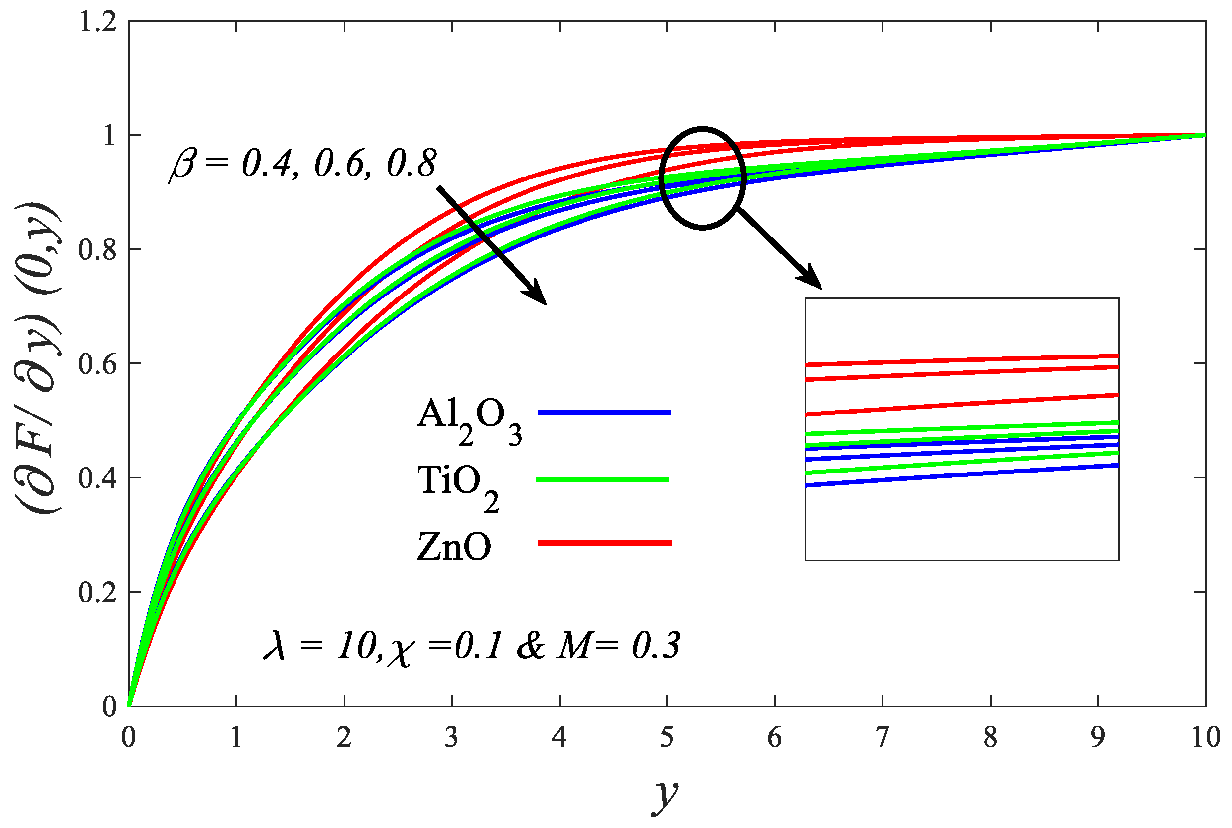
- Velocity is a decreasing function of or , while it is an increasing function of .
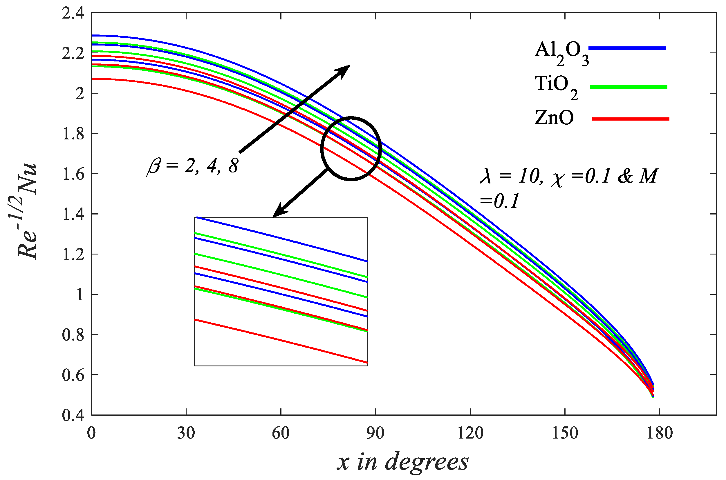
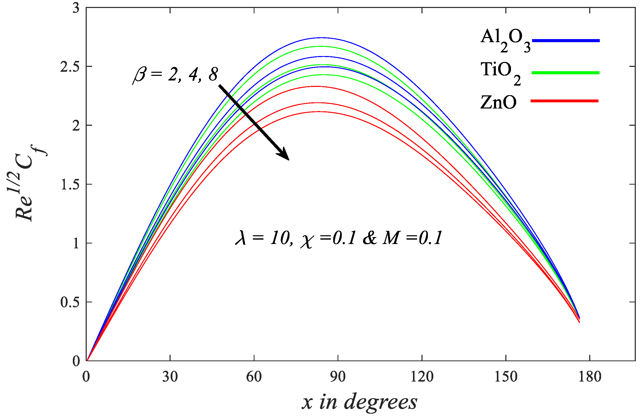
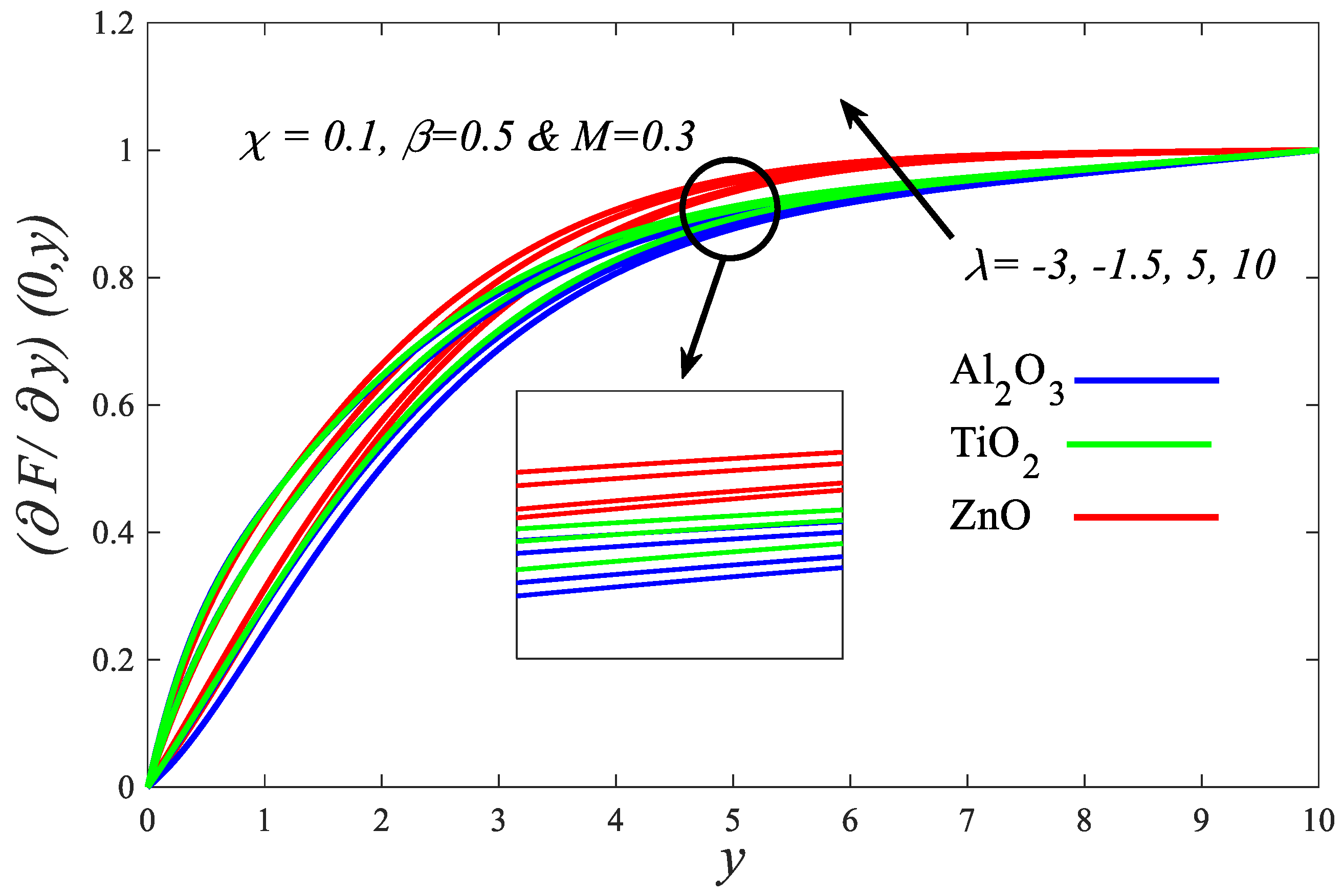
- Increasing increases , but increasing or decreases it.
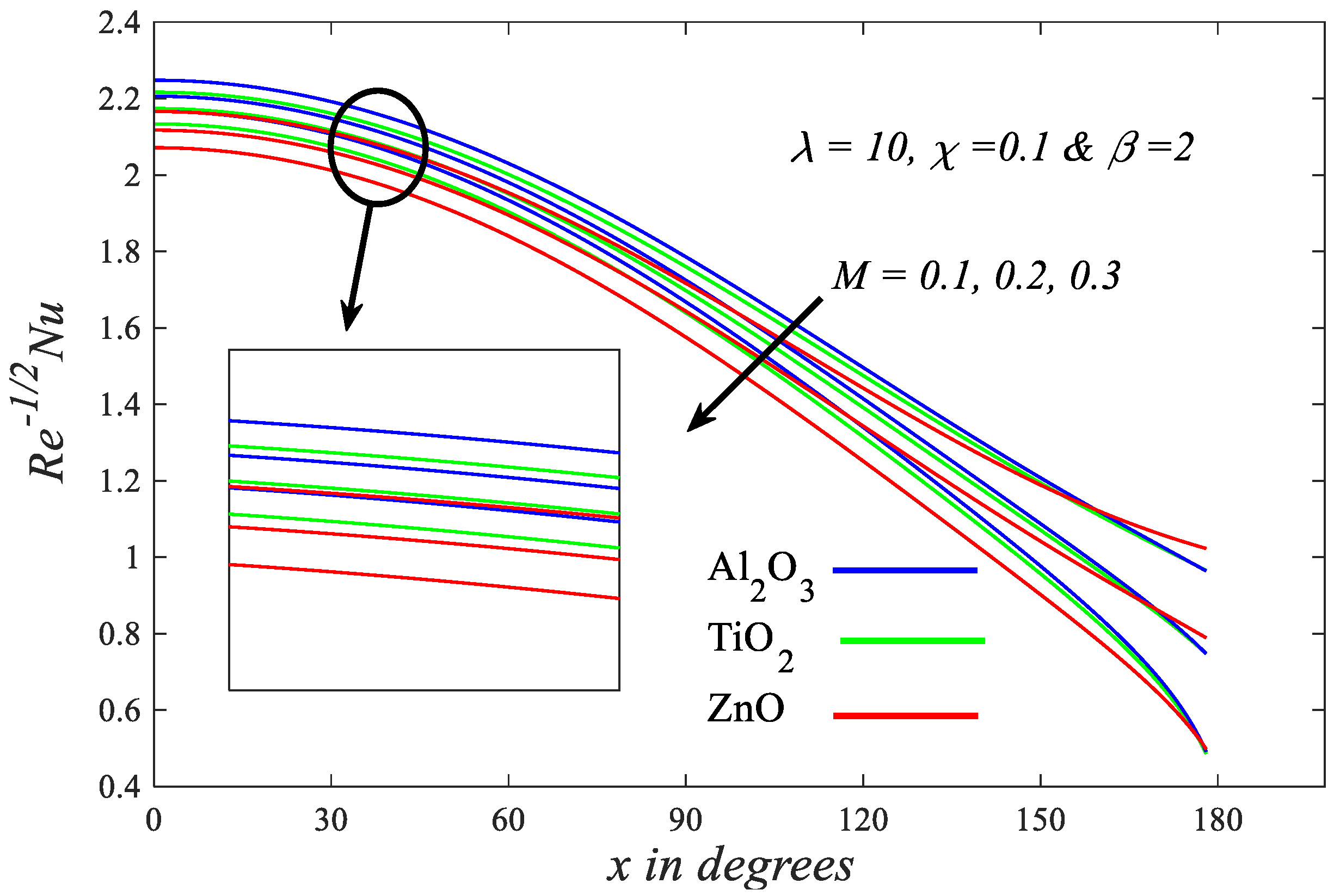
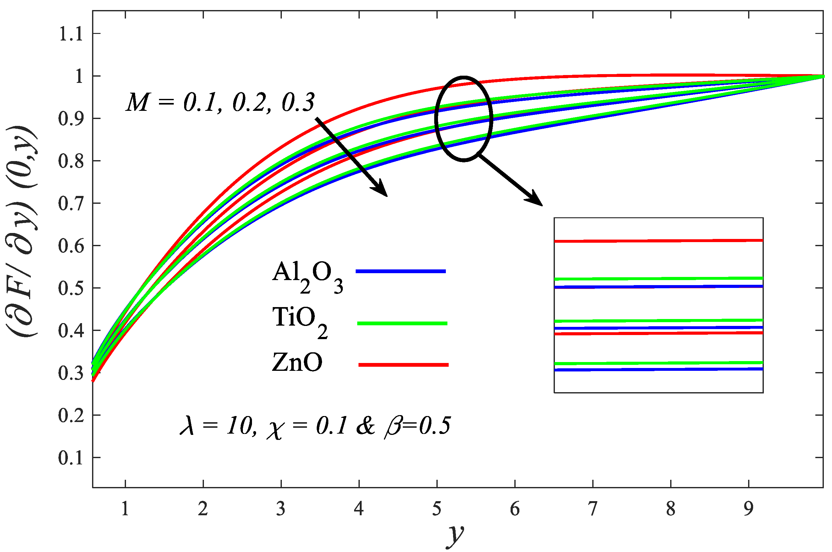
- The growth of each of the values of or boosts the rate of energy transport, whereas the growth of the values of M decays it.
- Whatever the values of the parameters examined in this article, Al2O3–kerosene oil has the highest heat transmission rate and skin friction. Moreover, it has the lowest temperature.
Author Contributions
Funding
Institutional Review Board Statement
Informed Consent Statement
Data Availability Statement
Conflicts of Interest
Nomenclature
| Radius of Cylinder | Temperature of the fluid | ||
| Magnetic field strength | Wall temperature | ||
| . | Skin friction coefficient | Ambient temperature | |
| Grashof number | -component of velocity | ||
| Gravity vector | -component of velocity | ||
| Thermal conductivity | Kinematic viscosity | ||
| Magnetic parameter | Velocity of external flow | ||
| Nusselt Number | Free stream velocity | ||
| Prandtl number | |||
| Yield stress | |||
| Reynolds number | |||
| Subscribt | |||
References
- Dash, R.; Mehta, K.; Jayaraman, G. Casson fluid flow in a pipe filled with a homogeneous porous medium. Int. J. Eng. Sci. 1996, 34, 1145–1156. [Google Scholar] [CrossRef]
- Casson, N. A flow equation for pigment-oil suspensions of the printing ink type. Rheol. Disperse Syst. 1959, 2, 84–102. [Google Scholar]
- Askadsky, A. Rheology of Polymers; Vinogradov, G.V., Malkin, A.Y., Eds.; Khimiya Publishers: Moscow, Russia, 1977; p. 438. (In Russian) [Google Scholar]
- Walawender, W.P.; Chen, T.Y.; Cala, D.F. An approximate Casson fluid model for tube flow of blood. Biorheology 1975, 12, 111–119. [Google Scholar] [CrossRef]
- Blair, G.S. An equation for the flow of blood, plasma and serum through glass capillaries. Nature 1959, 183, 613–614. [Google Scholar] [CrossRef] [PubMed]
- Ali, A.; Bukhari, Z.; Umar, M.; Ismail, M.A.; Abbas, Z. Cu and Cu-SWCNT Nanoparticles’ Suspension in Pulsatile Casson Fluid Flow via Darcy–Forchheimer Porous Channel with Compliant Walls: A Prospective Model for Blood Flow in Stenosed Arteries. Int. J. Mol. Sci. 2021, 22, 6494. [Google Scholar] [CrossRef]
- Mustafa, M.; Hayat, T.; Pop, I.; Aziz, A.l. Unsteady boundary layer flow of a Casson fluid due to an impulsively started moving flat plate. Heat Tran. Asian Res. 2011, 40, 563–576. [Google Scholar] [CrossRef]
- Mukhopadhyay, S.; De, P.R.; Bhattacharyya, K.; Layek, G. Casson fluid flow over an unsteady stretching surface. Ain Shams Eng. J. 2013, 4, 933–938. [Google Scholar] [CrossRef] [Green Version]
- Khalid, A.; Khan, I.; Khan, A.; Shafie, S. Unsteady MHD free convection flow of Casson fluid past over an oscillating vertical plate embedded in a porous medium. Eng. Sci. Technol. Int. J. 2015, 18, 309–317. [Google Scholar] [CrossRef] [Green Version]
- Animasaun, I.; Adebile, E.; Fagbade, A. Casson fluid flow with variable thermo-physical property along exponentially stretching sheet with suction and exponentially decaying internal heat generation using the homotopy analysis method. J. Niger. Math. Soc. 2016, 35, 1–17. [Google Scholar] [CrossRef] [Green Version]
- EL-Kabeir, S.; El-Zahar, E.; Rashad, A. Effect of chemical reaction on heat and mass transfer by mixed convection flow of casson fluid about a sphere with partial slip. J. Comput. Theor. Nanosci. 2016, 13, 5218–5226. [Google Scholar] [CrossRef]
- Makinde, O.; Sandeep, N.; Ajayi, T.; Animasaun, I. Numerical exploration of heat transfer and Lorentz force effects on the flow of MHD Casson fluid over an upper horizontal surface of a thermally stratified melting surface of a paraboloid of revolution. Int. J. Nonlinear Sci. Numer. Simul. 2018, 19, 93–106. [Google Scholar] [CrossRef]
- Thumma, T.; Wakif, A.; Animasaun, I.L. Generalized differential quadrature analysis of unsteady three-dimensional MHD radiating dissipative Casson fluid conveying tiny particles. Heat Transf. 2020, 49, 2595–2626. [Google Scholar] [CrossRef]
- Alwawi, F.A.; Alkasasbeh, H.T.; Rashad, A.; Idris, R. MHD natural convection of Sodium Alginate Casson nanofluid over a solid sphere. Res. Phys. 2020, 16, 102818. [Google Scholar] [CrossRef]
- Alwawi, F.A.; Alkasasbeh, H.T.; Rashad, A.; Idris, R. Heat transfer analysis of ethylene glycol-based Casson nanofluid around a horizontal circular cylinder with MHD effect. Proc. Inst. Mech. Eng. C. J. Mech. Eng. Sci. 2020, 234, 2569–2580. [Google Scholar] [CrossRef]
- Gul, T.; Ali, B.; Alghamdi, W.; Nasir, S.; Saeed, A.; Kumam, P.; Mukhtar, S.; Kumam, W.; Jawad, M. Mixed convection stagnation point flow of the blood based hybrid nanofluid around a rotating sphere. Sci. Rep. 2021, 11, 7460. [Google Scholar] [CrossRef]
- Alwawi, F.A.; Alkasasbeh, H.T.; Rashad, A.M.; Idris, R. Natural convection flow of Sodium Alginate based Casson nanofluid about a solid sphere in the presence of a magnetic field with constant surface heat flux. J. Phys. Conf. Ser. 2019, 1366, 012005. [Google Scholar] [CrossRef] [Green Version]
- Choi, S.U.; Eastman, J.A. Enhancing Thermal Conductivity of Fluids with Nanoparticles; Argonne National Lab.: Aurora, IL, USA, 1995. [Google Scholar]
- Eastman, J.A.; Choi, S.; Li, S.; Yu, W.; Thompson, L. Anomalously increased effective thermal conductivities of ethylene glycol-based nanofluids containing copper nanoparticles. Appl. Phys. Lett. 2001, 78, 718–720. [Google Scholar] [CrossRef]
- Suganthi, K.; Vinodhan, V.L.; Rajan, K. Heat transfer performance and transport properties of ZnO–ethylene glycol and ZnO–ethylene glycol–water nanofluid coolants. Appl. Energy 2014, 135, 548–559. [Google Scholar] [CrossRef]
- Han, D.; He, W.; Asif, F. Experimental study of heat transfer enhancement using nanofluid in double tube heat exchanger. Energy Procedia 2017, 142, 2547–2553. [Google Scholar] [CrossRef]
- Dareh, F.R.; Haghshenasfard, M.; Esfahany, M.N.; Jazi, H.R.S. An experimental investigation of pool boiling characteristics of alumina-water nanofluid over micro-/nanostructured surfaces. Heat Transf. Eng. 2019, 40, 1691–1708. [Google Scholar] [CrossRef]
- Hu, B.; Zhang, S.; Wang, D.; Chen, X.; Si, X.; Zhang, D. Experimental study of nucleate pool boiling heat transfer of self-rewetting solution by surface functionalization with TiO2 nanostructure. Can. J. Chem. Eng. 2019, 97, 1399–1406. [Google Scholar] [CrossRef]
- Ali, H.M.; Generous, M.M.; Ahmad, F.; Irfan, M. Experimental investigation of nucleate pool boiling heat transfer enhancement of TiO2-water based nanofluids. Appl. Therm. Eng. 2017, 113, 1146–1151. [Google Scholar] [CrossRef]
- Dehghani-Ashkezari, E.; Salimpour, M.R. Effect of groove geometry on pool boiling heat transfer of water-titanium oxide nanofluid. Heat Mass Transf. 2018, 54, 3473–3481. [Google Scholar] [CrossRef]
- Al-Hossainy, A.F.; Eid, M.R. Structure, DFT calculations and heat transfer enhancement in [ZnO/PG+ H2O] C hybrid nanofluid flow as a potential solar cell coolant application in a double-tube. J. Mater. Sci. Mater. Electron. 2020, 31, 15243–15257. [Google Scholar] [CrossRef]
- Sheikholeslami, M.; Hayat, T.; Alsaedi, A. MHD free convection of Al2O3–water nanofluid considering thermal radiation: A numerical study. Int. J. Heat Mass Transf. 2016, 96, 513–524. [Google Scholar] [CrossRef]
- Sawicka, D.; Baars, A.; Cieśliński, J.T.; Smoleń, S. Numerical simulation of natural convection of Glycol-Al2O3 nanofluids from a horizontal cylinder. Heat Transf. Eng. 2021, 42, 328–336. [Google Scholar] [CrossRef]
- Minea, A.A.; Lorenzini, G. A numerical study on ZnO based nanofluids behavior on natural convection. Int. J. Heat Mass Transf. 2017, 114, 286–296. [Google Scholar] [CrossRef]
- Demir, H.; Dalkilic, A.; Kürekci, N.; Duangthongsuk, W.; Wongwises, S. Numerical investigation on the single phase forced convection heat transfer characteristics of TiO2 nanofluids in a double-tube counter flow heat exchanger. Int. Commun. Heat Mass Transf. 2011, 38, 218–228. [Google Scholar] [CrossRef]
- Burggraf, J.; Farber, P.; Karpaiya, K.R.; Ueberholz, P. Numerical Investigation of Laminar Flow Heat Transfer of TiO2-Water Nanofluid in a Heated Pipe. Heat Transf. Eng. 2020, 42, 1635–1647. [Google Scholar] [CrossRef]
- Terenzi, A.; Marchetti, B.; Leporini, M.; Poesio, P.; Liu, J. Experimental and Numerical Study of Multiphase Flow Phenomena and Models in Oil & Gas Industry; Elsevier: Amsterdam, The Netherlands, 2019; Volume 5, p. 113. [Google Scholar]
- Leporini, M.; Corvaro, F.; Marchetti, B.; Polonara, F.; Benucci, M. Experimental and numerical investigation of natural convection in tilted square cavity filled with air. Exp. Therm. Fluid Sci. 2018, 99, 572–583. [Google Scholar] [CrossRef]
- Giacchetta, G.; Leporini, M.; Marchetti, B.; Terenzi, A. Numerical study of choked two-phase flow of hydrocarbons fluids through orifices. J. Loss Prev. Process Ind. 2014, 27, 13–20. [Google Scholar] [CrossRef]
- Liu, X.; Zhang, G.; Li, J.; Shi, G.; Zhou, M.; Huang, B.; Tang, Y.; Song, X.; Yang, W. Deep learning for Feynman’s path integral in strong-field time-dependent dynamics. Phys. Rev. Lett. 2020, 124, 113202. [Google Scholar] [CrossRef] [PubMed] [Green Version]
- Yang, W.; Lin, Y.; Chen, X.; Xu, Y.; Zhang, H.; Ciappina, M.; Song, X. Wave mixing and high-harmonic generation enhancement by a two-color field driven dielectric metasurface. Chin. Opt. Lett. 2021, 19, 123202. [Google Scholar] [CrossRef]
- Kanule, J.; Ng’etich, W. Numerical modeling of translational dynamics for shallow landslides based on flume tests–special case of spherical-cap-shaped slope sections. Geol. Ecol. Landsc. 2020, 4, 151–158. [Google Scholar] [CrossRef]
- Cui, L.; Ji, M.; Zhou, S. Wave Loading on a Group of Cylinders in Fairly Perfect Fluid. J. Coast. Res. 2020, 103, 288–292. [Google Scholar] [CrossRef]
- Ali, F.; Aamina, K.I.; Sheikh, N.; Gohar, M.; Tlili, I. Effects of different shaped nanoparticles on the performance of engine-oil and kerosene-oil: A generalized Brinkman-type fluid model with non-singular kernel. Sci. Rep. 2018, 8, 15285. [Google Scholar] [CrossRef] [PubMed]
- Hussanan, A.; Salleh, M.Z.; Khan, I.; Shafie, S. Convection heat transfer in micropolar nanofluids with oxide nanoparticles in water, kerosene and engine oil. J. Mol. Liq. 2017, 229, 482–488. [Google Scholar] [CrossRef] [Green Version]
- Ellahi, R.; Zeeshan, A.; Shehzad, N.; Alamri, S.Z. Structural impact of Kerosene-Al2O3 nanoliquid on MHD Poiseuille flow with variable thermal conductivity: Application of cooling process. J. Mol. Liq. 2018, 264, 607–615. [Google Scholar] [CrossRef]
- Afridi, M.; Qasim, M.; Khan, N.A.; Hamdani, M. Heat transfer analysis of Cu–Al2O3–water and Cu–Al2O3–kerosene oil hybrid nanofluids in the presence of frictional heating: Using 3-stage Lobatto IIIA formula. J. Nanofluids 2019, 8, 885–891. [Google Scholar] [CrossRef]
- Swalmeh, M.Z.; Alkasasbeh, H.T.; Hussanan, A.; Mamat, M. Numerical investigation of heat transfer enhancement with Ag-GO water and kerosene oil based micropolar nanofluid over a solid sphere. J. Adv. Res. Fluid Mech. Therm. Sci. 2019, 59, 269–282. [Google Scholar]
- Alkasasbeh, H.T.; Swalmeh, M.Z.; Hussanan, A.; Mamat, M. Numerical Solution of Heat Transfer Flow in Micropolar Nanofluids with Oxide Nanoparticles in Water and Kerosene Oil about a Horizontal Circular Cylinder. Int. J. Appl. Math. 2019, 49, 1–8. [Google Scholar]
- Upreti, H.; Pandey, A.K.; Kumar, M. Thermophoresis and suction/injection roles on free convective MHD flow of Ag–kerosene oil nanofluid. J. Comput. Des. Eng. 2020, 7, 386–396. [Google Scholar] [CrossRef]
- Eid, M.R.; Mabood, F. Entropy analysis of a hydromagnetic micropolar dusty carbon NTs-kerosene nanofluid with heat generation: Darcy–Forchheimer scheme. J. Therm. Anal. Calorim. 2021, 143, 2419–2436. [Google Scholar] [CrossRef]
- Qasim, M.; Khan, Z.H.; Khan, W.A.; Ali Shah, I. MHD boundary layer slip flow and heat transfer of ferrofluid along a stretching cylinder with prescribed heat flux. PLoS ONE 2014, 9, e83930. [Google Scholar] [CrossRef] [PubMed]
- Tamoor, M.; Waqas, M.; Khan, M.I.; Alsaedi, A.; Hayat, T. Magnetohydrodynamic flow of Casson fluid over a stretching cylinder. Res. Phys. 2017, 7, 498–502. [Google Scholar] [CrossRef]
- Alizadeh, R.; Karimi, N.; Nourbakhsh, A. Effects of radiation and magnetic field on mixed convection stagnation-point flow over a cylinder in a porous medium under local thermal non-equilibrium. J. Therm. Anal. Calorim. 2020, 140, 1371–1391. [Google Scholar] [CrossRef] [Green Version]
- Krishna, M.V.; Ahamad, N.A.; Chamkha, A.J. Hall and ion slip impacts on unsteady MHD convective rotating flow of heat generating/absorbing second grade fluid. Alex. Eng. J. 2021, 60, 845–858. [Google Scholar] [CrossRef]
- Rashad, A.; Nabwey, H.A. Gyrotactic mixed bioconvection flow of a nanofluid past a circular cylinder with convective boundary condition. J. Taiwan Inst. Chem. Eng. 2019, 99, 9–17. [Google Scholar] [CrossRef]
- Vijaybabu, T. Influence of porous circular cylinder on MHD double-diffusive natural convection and entropy generation. Int. J. Mech. Sci. 2021, 206, 106625. [Google Scholar] [CrossRef]
- Krishna, M.V.; Chamkha, A.J. Hall and ion slip effects on MHD rotating flow of elastico-viscous fluid through porous medium. Int. Commun. Heat Mass Transf. 2020, 113, 104494. [Google Scholar] [CrossRef]
- Krishna, M.V.; Ahamad, N.A.; Chamkha, A.J. Hall and ion slip effects on unsteady MHD free convective rotating flow through a saturated porous medium over an exponential accelerated plate. Alex. Eng. J. 2020, 59, 565–577. [Google Scholar] [CrossRef]
- Krishna, M.V.; Chamkha, A.J. Hall and ion slip effects on MHD rotating boundary layer flow of nanofluid past an infinite vertical plate embedded in a porous medium. Res. Phys. 2019, 15, 102652. [Google Scholar] [CrossRef]
- Krishna, M.V.; Jyothi, K.; Chamkha, A.J. Heat and mass transfer on MHD flow of second-grade fluid through porous medium over a semi-infinite vertical stretching sheet. J. Porous Media 2020, 23, 751–765. [Google Scholar] [CrossRef]
- Krishna, M.V.; Swarnalathamma, B.; Chamkha, A.J. Investigations of Soret, Joule and Hall effects on MHD rotating mixed convective flow past an infinite vertical porous plate. J. Ocean. Eng. Sci. 2019, 4, 263–275. [Google Scholar] [CrossRef]
- Krishna, M.V.; Reddy, M.G.; Chamkha, A.J. Heat and Mass Transfer on MHD Free Convective Flow over an Infinite Nonconducting Vertical Flat Porous Plate. Int. J. Fluid Mech. Res. 2019, 46, 1–25. [Google Scholar] [CrossRef]
- Krishna, M.V.; Anand, P.; Chamkha, A.J. Heat and mass transfer on free convective flow of amicropolar fluid through a porous surface with inclined magnetic field and hall effects. Spec. Top. Rev. Porous Media Int. J. 2019, 10, 203–223. [Google Scholar] [CrossRef]
- Buongiorno, J. Convective transport in nanofluids. J. Heat Transfer. 2006, 128, 240–250. [Google Scholar] [CrossRef]
- Tiwari, R.K.; Das, M.K. Heat transfer augmentation in a two-sided lid-driven differentially heated square cavity utilizing nanofluids. Int. J. Heat Mass Transf. 2007, 50, 2002–2018. [Google Scholar] [CrossRef]
- Mohamad, A. Heat transfer enhancements in heat exchangers fitted with porous media Part I: Constant wall temperature. Int. J. Therm. Sci. 2003, 42, 385–395. [Google Scholar] [CrossRef]
- Da Riva, E.; Del Col, D. Numerical simulation of laminar liquid film condensation in a horizontal circular minichannel. J. Heat Transf. 2012, 134, 051019. [Google Scholar] [CrossRef]
- Lee, H.C.; Do Oh, B.; Bae, S.W.; Kim, M.H. Single bubble growth in saturated pool boiling on a constant wall temperature surface. Int. J. Multiph. Flow 2003, 29, 1857–1874. [Google Scholar] [CrossRef]
- Lee, H.C.; Oh, B.D.; Bae, S.W.; Kim, M.H.; Lee, J.Y.; Song, I.S. Partial nucleate boiling on the microscale heater maintaining constant wall temperature. J. Nucl. Sci. Technol. 2003, 40, 768–774. [Google Scholar] [CrossRef]
- Merkin, J. Free convection boundary layer on an isothermal horizontal cylinder. In Heat Transfer Conference, St. Louis, MO, USA, 9–11 August 1976; American Society of Mechanical Engineers and American Institute of Chemical Engineers: St. Louis, MO, USA, 1976; p. 5. [Google Scholar]
- Merkin, J. Mixed convection from a horizontal circular cylinder. Int. J. Heat Mass Transf. 1977, 20, 73–77. [Google Scholar] [CrossRef]
- Nazar, R.; Amin, N.; Pop, I. Mixed convection boundary-layer flow from a horizontal circular cylinder in micropolar fluids: Case of constant wall temperature. Int. J. Numer. Method H. 2003, 13, 86–109. [Google Scholar] [CrossRef]
- Nazar, R.; Amin, N.S.; Pop, I. Mixed convection boundary layer flow from a horizontal circular cylinder in a micropolar fluid: Case of constant wall heat flux. Int. J. Fluid Mech. Res. 2004, 31, 143–159. [Google Scholar] [CrossRef]
- Tham, L.; Nazar, R.; Pop, I. Mixed convection boundary layer flow from a horizontal circular cylinder in a nanofluid. Int. J. Numer. Method H. 2012, 22, 576–606. [Google Scholar] [CrossRef]
- Rashad, A.; Chamkha, A.; Modather, M. Mixed convection boundary-layer flow past a horizontal circular cylinder embedded in a porous medium filled with a nanofluid under convective boundary condition. Comput. Fluids 2013, 86, 380–388. [Google Scholar] [CrossRef]
- Hamarsheh, A.S.; Alwawi, F.A.; Alkasasbeh, H.T.; Rashad, A.M.; Idris, R. Heat transfer improvement in MHD natural convection flow of graphite oxide/carbon nanotubes-methanol based casson nanofluids past a horizontal circular cylinder. Processes 2020, 8, 1444. [Google Scholar] [CrossRef]
- Hussanan, A.; Salleh, M.Z.; Alkasasbeh, H.T.; Khan, I. MHD flow and heat transfer in a Casson fluid over a nonlinearly stretching sheet with Newtonian heating. Heat Transf. Res. 2018, 49, 1185–1198. [Google Scholar] [CrossRef]
- Pop, I.; Ingham, D.B. Convective Heat Transfer: Mathematical and Computational Modelling of Viscous Fluids and Porous Media; Elsevier: Amsterdam, The Netherlands, 2001. [Google Scholar]
- Acheson, D.J. Elementary Fluid Dynamics; Acoustical Society of America, Oxford University Press Inc.: New York, NY, USA, 1991. [Google Scholar]
- Manzoor, T.; Zafar, M.; Iqbal, S.; Nazar, K.; Ali, M.; Saleem, M.; Manzoor, S.; Kim, W.Y. Theoretical Analysis of Roll-Over-Web Surface Thin Layer Coating. Coatings 2020, 10, 691. [Google Scholar] [CrossRef]
- Manzoor, T.; Nazar, K.; Zafar, M.; Iqbal, S.; Ali, M.; Kim, W.Y.; Saleem, M.; Manzoor, S. Analysis of a thin layer formation of third-grade fluid. Coatings 2019, 9, 741. [Google Scholar] [CrossRef] [Green Version]
- Ahmed, S.E.; Mansour, M.; Hussein, A.K.; Mallikarjuna, B.; Almeshaal, M.A.; Kolsi, L. MHD mixed convection in an inclined cavity containing adiabatic obstacle and filled with Cu–water nanofluid in the presence of the heat generation and partial slip. J. Therm. Anal. Calorim. 2019, 138, 1443–1460. [Google Scholar] [CrossRef]
- Dinarvand, S.; Hosseini, R.; Pop, I. Axisymmetric mixed convective stagnation-point flow of a nanofluid over a vertical permeable cylinder by Tiwari-Das nanofluid model. Powder Technol. 2017, 311, 147–156. [Google Scholar] [CrossRef]
- Molla, M.; Hossain, M.; Taher, M. Magnetohydrodynamic natural convection flow on a sphere with uniform heat flux in presence of heat generation. Acta Mech. 2006, 186, 75–86. [Google Scholar] [CrossRef]
- Keller, H.B.; Bramble, J. Numerical solutions of partial differential equations. Mathematics 1970, 1, 81–94. [Google Scholar]
- Jones, E. An asymptotic outer solution applied to the Keller box method. J. Comput. Phys. 1981, 40, 411–429. [Google Scholar] [CrossRef]
- Cebeci, T.; Bradshaw, P. Physical and Computational Aspects of Convective Heat Transfer; Springer Science & Business Media: New York, NY, USA, 2012. [Google Scholar]
- Shafie, S.; Gul, A.; Khan, I. Molybdenum disulfide nanoparticles suspended in water-based nanofluids with mixed convection and flow inside a channel filled with saturated porous medium. AIP Conf. Proc. 2016, 1775, 030042. [Google Scholar]
- Brown, S.; Stewartson, K. Laminar separation. Annu. Rev. Fluid Mech. 1969, 1, 45–72. [Google Scholar] [CrossRef]
- Curle, N. Development and separation of a laminar boundary layer with an exponentially increasing pressure gradient. Q. J. Mech. Appl. Math. 1981, 34, 383–396. [Google Scholar] [CrossRef]
- Pauley, L.L.; Moin, P.; Reynolds, W.C. The structure of two-dimensional separation. J. Fluid Mech. 1990, 220, 397–411. [Google Scholar] [CrossRef]
- Miles, J.W. Boundary-layer separation on a sphere in a rotating flow. J. Fluid Mech. 1971, 45, 513–526. [Google Scholar] [CrossRef]


| Thermo-Physical Property | Kerosene Oil | Al2O3 | TiO2 | ZnO |
|---|---|---|---|---|
| 783 | 3970 | 4230 | 5600 | |
| 2090 | 765 | 650 | 502.7 | |
| 0.15 | 40 | 8.9528 | 13 | |
| 21 | 0.85 | 0.9 | 0.431 | |
| 22.85 | - | - | - |
| −0.5 | 0 | 2 | |||||||
|---|---|---|---|---|---|---|---|---|---|
| Tham et al. | Present | Tham et al. | Present | Tham et al. | Present | ||||
| 0 | 0.0000 | 0.0000 | 0.0000 | 0.0000 | 0.0000 | 0.0000 | 0.0000 | 0.0000 | 0.0000 |
| 0.2 | 0.1869 | 0.1868 | 0.0500 | 0.2425 | 0.2437 | 0.4900 | 0.4349 | 0.4136 | 0.4800 |
| 0.4 | 0.3503 | 0.3503 | 0.0000 | 0.4619 | 0.4573 | 0.9900 | 0.8452 | 0.8456 | 0.0500 |
| 0.6 | 0.4690 | 0.4689 | 0.0200 | 0.6377 | 0.6347 | 0.4700 | 1.2084 | 1.1996 | 0.7300 |
| 0.8 | 0.5244 | 0.5235 | 0.1700 | 0.7525 | 0.7519 | 0.0700 | 1.5061 | 1.4929 | 0.8700 |
| 1.0 | 0.5012 | 0.5048 | 0.7100 | 0.7944 | 0.7965 | 0.2600 | 1.7252 | 1.7161 | 0.5200 |
| 1.2 | 0.3834 | 0.3825 | 0.2300 | 0.7566 | 0.7615 | 0.6400 | 1.8586 | 1.8539 | 0.2500 |
| 1.4 | 0.1138 | 0.1134 | 0.3500 | 0.6370 | 0.6347 | 0.3600 | 1.9060 | 1.9056 | 0.0200 |
| 1.6 | 0.4333 | 0.4343 | 0.2300 | 1.8735 | 1.8769 | 0.1800 | |||
| 1.8 | 0.0934 | 0.0888 | 0.4900 | 1.7726 | 1.7791 | 0.3600 | |||
| 2.0 | 1.6188 | 1.6275 | 0.5300 | ||||||
| 2.2 | 1.4297 | 1.4397 | 0.6900 | ||||||
| 2.4 | 1.2225 | 1.2331 | 0.8600 | ||||||
| 2.6 | 1.0116 | 1.0121 | 0.0500 | ||||||
| 2.8 | 0.8052 | 0.8054 | 0.0200 | ||||||
| 3.0 | 0.6029 | 0.6031 | 0.0300 | ||||||
| 0.4564 | 0.4564 | 0.0000 | |||||||
| −0.5 | 0 | 2 | |||||||
|---|---|---|---|---|---|---|---|---|---|
| Tham et al. | Present | Tham et al. | Present | Tham et al. | Present | ||||
| 0 | 0.5421 | 0.5421 | 0.0000 | 0.5705 | 0.5705 | 0.0000 | 0.6515 | 0.6515 | 0.0000 |
| 0.2 | 0.5379 | 0.5383 | 0.0700 | 0.5668 | 0.5672 | 0.0700 | 0.6487 | 0.6490 | 0.0400 |
| 0.4 | 0.5257 | 0.5264 | 0.1300 | 0.5563 | 0.5569 | 0.1000 | 0.6407 | 0.6411 | 0.0600 |
| 0.6 | 0.5050 | 0.5049 | 0.0100 | 0.5387 | 0.5395 | 0.1400 | 0.6275 | 0.6273 | 0.0300 |
| 0.8 | 0.4751 | 0.4752 | 0.0200 | 0.5140 | 0.5139 | 0.0100 | 0.6094 | 0.6101 | 0.1100 |
| 1.0 | 0.4342 | 0.4343 | 0.0200 | 0.4818 | 0.4837 | 0.3900 | 0.5867 | 0.5864 | 0.0500 |
| 1.2 | 0.3766 | 0.3770 | 0.1000 | 0.4415 | 0.4417 | 0.0400 | 0.5598 | 0.5596 | 0.0300 |
| 1.4 | 0.2683 | 0.2692 | 0.3300 | 0.3914 | 0.3917 | 0.0700 | 0.5292 | 0.5291 | 0.0100 |
| 1.6 | 0.3260 | 0.3266 | 0.1800 | 0.4955 | 0.4972 | 0.3400 | |||
| 1.8 | 0.2051 | 0.2068 | 0.8200 | 0.4595 | 0.4594 | 0.0200 | |||
| 2.0 | 0.4219 | 0.4219 | 0.0000 | ||||||
| 2.2 | 0.3837 | 0.3856 | 0.4900 | ||||||
| 2.4 | 0.3458 | 0.3458 | 0.0000 | ||||||
| 2.6 | 0.3090 | 0.3108 | 0.5800 | ||||||
| 2.8 | 0.2737 | 0.2737 | 0.0000 | ||||||
| 3.0 | 0.2394 | 0.2411 | 0.7100 | ||||||
| 0.2144 | 0.2144 | 0.0000 | |||||||
Publisher’s Note: MDPI stays neutral with regard to jurisdictional claims in published maps and institutional affiliations. |
© 2022 by the authors. Licensee MDPI, Basel, Switzerland. This article is an open access article distributed under the terms and conditions of the Creative Commons Attribution (CC BY) license (https://creativecommons.org/licenses/by/4.0/).
Share and Cite
Alwawi, F.A.; Hamarsheh, A.S.; Alkasasbeh, H.T.; Idris, R. Mixed Convection Flow of Magnetized Casson Nanofluid over a Cylindrical Surface. Coatings 2022, 12, 296. https://doi.org/10.3390/coatings12030296
Alwawi FA, Hamarsheh AS, Alkasasbeh HT, Idris R. Mixed Convection Flow of Magnetized Casson Nanofluid over a Cylindrical Surface. Coatings. 2022; 12(3):296. https://doi.org/10.3390/coatings12030296
Chicago/Turabian StyleAlwawi, Firas A., Abdulkareem Saleh Hamarsheh, Hamzeh T. Alkasasbeh, and Ruwaidiah Idris. 2022. "Mixed Convection Flow of Magnetized Casson Nanofluid over a Cylindrical Surface" Coatings 12, no. 3: 296. https://doi.org/10.3390/coatings12030296