Article

Electron Beam Sintering of Composite Al2O3-ZrO2 Ceramics in the Forevacuum Pressure Range

1
Laboratory of Plasma Electronics, Tomsk State University of Control Systems and Radioelectronics, 634050 Tomsk, Russia
2
Laboratory of Plasma Sources, Institute of High Current Electronics SB RAS, 634034 Tomsk, Russia
*
Author to whom correspondence should be addressed.
Coatings 2022, 12(2), 278; https://doi.org/10.3390/coatings12020278
Submission received: 5 January 2022 / Revised: 14 February 2022 / Accepted: 18 February 2022 / Published: 20 February 2022
(This article belongs to the Special Issue Electron-Ion-Plasma Technology Applied to Surface Engineering)

Abstract

:
We describe our investigations of electron beam sintering of multilayer ZrO2-Al2O3 composite ceramics in the forevacuum pressure range (~30 Pa). To generate the electron beam, a plasma-cathode electron source operating in the forevacuum pressure range was used; this kind of source provides the capability of direct processing of non-conducting materials. We studied the effect of electron beam sintering on the temperature drop with sample depth for different layer thicknesses and determined the optimal layer thickness to ensure minimal temperature drop. We show that in order to minimize the temperature difference and improve the sintering, it is necessary to take into account the thermophysical parameters of the sintered materials. Forming a layered structure taking into account the coefficient of thermal conductivity of the layer materials allows a reduction in the temperature gradient by 150 °C for samples of 3 mm thickness.

1. Introduction

Ceramic materials are widely used in many industries: microelectronic, automotive, aerospace, and medicine. Gradient ceramics, in particular, Al2O3-ZrO2-based systems, are replacing several structural metals and alloys. Composite ceramics based on aluminum oxide and zirconium dioxide are used to make cutting tools, biomedical implants, molds, parts of prostheses, bulletproof vests, oxygen sensors, and more [1,2,3,4,5,6]. Composite ceramics are characterized by some unique physical and chemical properties not found in other classes of materials, such as hardness, compressive strength, bending, high corrosion resistance, resistance to aggressive media and thermal shock, high-temperature serviceability, and thermal expansion coefficients close to those of metals and alloys [7].
Gradient materials are materials with a gradual variation of mechanical or chemical properties as a function of depth below the sample surface [8,9,10,11]. The main methods of forming gradient materials can be divided into two types. In one technique, the gradient structure is formed sequentially and layer by layer; in the other, by sintering a multilayer sample. The first type includes selective sintering by an electron or laser beam [12,13]; the second type includes hot pressing and microwave and spark plasma sintering [14,15,16]. The advantage of forming the gradient structure in a sequential and layer-by-layer manner is the possibility of creating samples of complex shape, although with greater porosity [17]. Samples fabricated using the second method can only have a simple shape but are less porous because of the peculiarities of sintering. Sintering of powders involves issues of controlling the rate and uniformity of sample heating. Heating and sintering in a furnace requires a lengthy exposure at high temperatures and is energy inefficient. In the case of sintering by laser irradiation, sample heating begins at the irradiated surface and is not distributed uniformly [18]. The resulting temperature gradient leads to inhomogeneous grain size distribution and uneven sample density throughout the depth of the material [19]. These problems can be ameliorated by increasing the heating time, which increases the duration of the entire process. Further, the efficiency of energy transfer of laser radiation to the sample depends on its optical properties, and this imposes certain constraints on the choice of sintered materials.
In the case of heating with an electron beam, the optical properties of the target are not important; however, there arises the problem of offsetting the electrical charge carried to the dielectric target by the beam. Surface charging causes electron beam defocusing and deteriorates the efficiency of beam power transfer to the target. The solution to this problem lies in using a forevacuum-pressure plasma-cathode electron source [20]. This kind of source is capable of generating beams in the 1–100 Pa pressure range, and the surface charge is compensated by the ion flux from the beam–plasma formed by beam propagation at such enhanced pressure [21]. We have previously shown that electron beams formed by forevacuum plasma-cathode sources are advantageous for sintering ceramic compacts [22,23,24,25]. In the present work, we have used gradient structures with different layer thicknesses in order to improve the uniformity of target heating. By appropriate selection of the thickness of layers of materials with different thermal properties, it is possible to decrease the temperature drop and improve the homogeneity of the sintered sample.
The aim of the work described here was to explore the regimes of electron beam sintering of multilayer composite ceramics and to determine the optimal relationship of layer thicknesses that ensures minimal temperature drop with a depth below the sample surface.

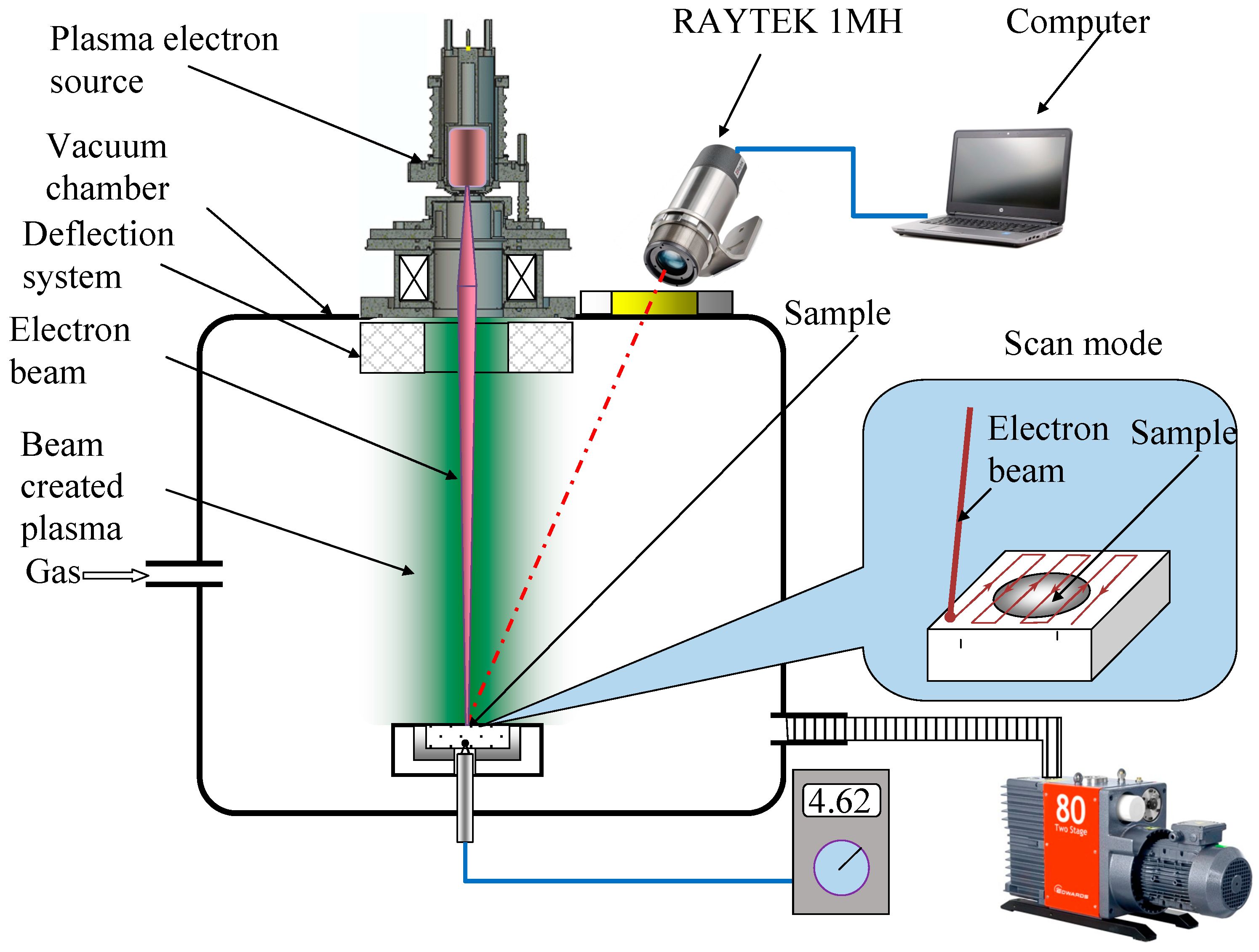
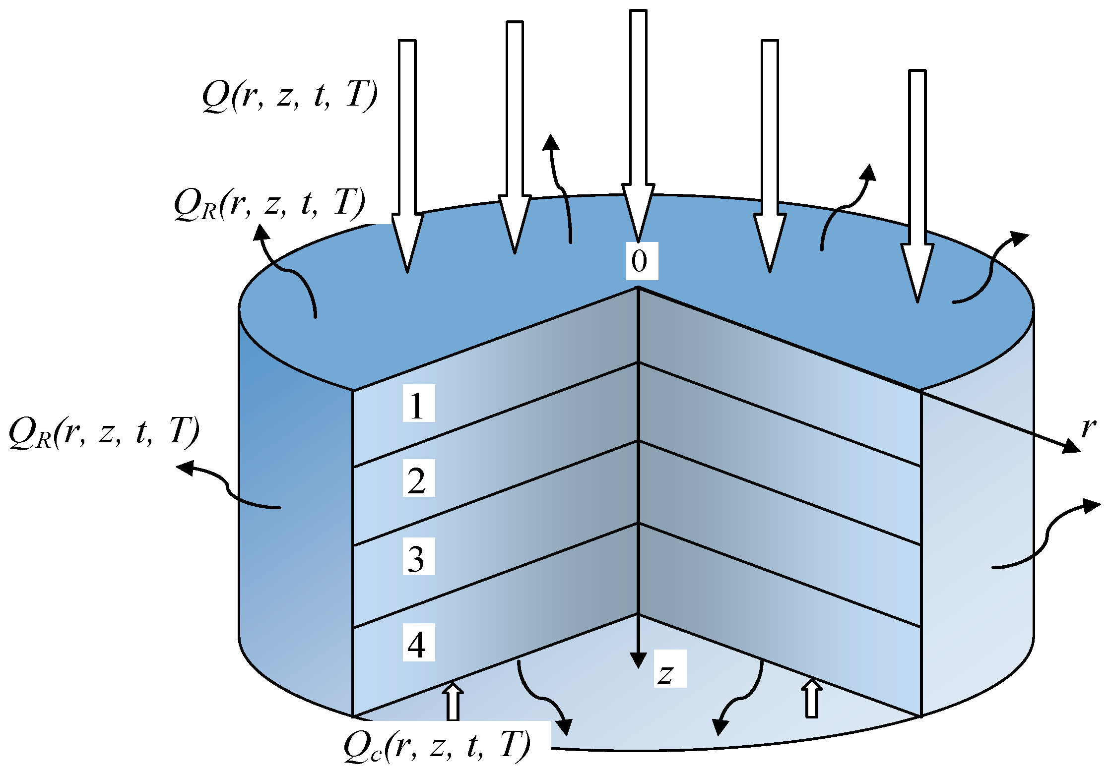
2. Materials and Methods
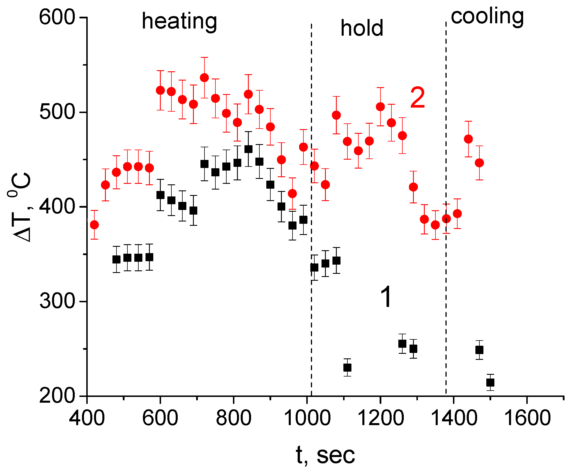
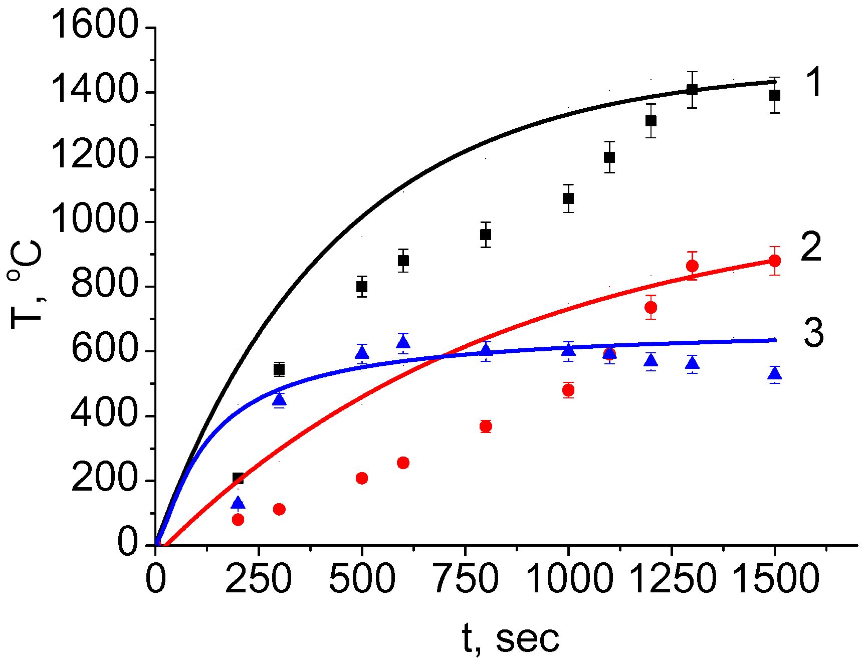
The experimental setup used for electron beam sintering of composite ceramic samples is shown in Figure 1.
A forevacuum-pressure plasma-cathode electron beam source was mounted on the vacuum chamber. The source formed a thin (about 0.7–1 mm diameter) focused electron beam with current up to 25 mA and electron energy up to 7 keV.
We used compacted samples made of powders of zirconium dioxide and aluminum oxide and their mixtures in various mass proportions. The particle size of the initial Al2O3 and ZrO2 powders was 10 microns. Samples were made from 100% (wt.) Al2O3 powder and 100% (wt.) ZrO2 powder. Additionally, layered samples were made of four layers with different compositions by packing powders into a mold one after another; the layers were 100% aluminum oxide, a mixture of 70% (wt.) Al2O3 and 30% (wt.) ZrO2, a mixture of 30% (wt.) Al2O3 and 70% (wt.) ZrO2, and 100% (wt.) ZrO2. We made five samples of each type. The samples were compacted using a hydraulic press at 115 MPa and held under pressure for 5 min. After compacting, the samples had a disk shape of diameter 10.2 ± 0.1 mm and thickness 3 ± 0.1 mm. The compacted sample was placed on a graphite crucible. The vacuum chamber was first evacuated and then flushed with helium operating gas; the pressure was set to 30 Pa, and the forevacuum plasma electron source was turned on. Due to the formation of a dense beam–plasma in the electron beam transport region and thus the availability of a positive ion flux from this plasma, no additional measures to compensate for the negative charge on the dielectric surface were needed. In this way, we could carry out efficient electron beam treatment of dielectric materials with low-energy electrons.
To ensure uniform heating of the samples, the electron beam deflection system was set to raster the beam over the sample surface at a frequency of 100 Hz and a scan area of 15 mm × 15 mm. The temperature of the sample’s beam-irradiated surface was measured during the sintering process using a RAYTEK 1MH infrared pyrometer (Raytek Corp., Santa Cruz, CA, USA) with a measuring range of 550 to 3000 °C, which fed data into a computer. The measurement error of the pyrometer, according to the user manual, is ±0.3% of the measured value +1 °C. That is, when measuring the maximum temperature of 3000 °C, the error is less than 10 °C. The temperature of the sample backside surface, not subject to electron beam irradiation, was monitored by a platinum–iridium thermocouple with a measuring range up to 1750 °C; the thermal electromotive force (EMF) was measured using a high-resistance voltmeter and converted to a temperature value. To ensure tight contact between the thermocouple and the sample, a 0.5 mm deep hole was made in the latter, into which the thermocouple junction was inserted.
During sintering, the electron energy was gradually increased from 2 to 7 keV and the beam current from 18 to 25 mA. To reduce the heat load on the sample and improve the heating uniformity, the rate of electron beam power change was limited to 5 W/min during the initial stage of heating; when the sample surface temperature reached 1000 °C, the rate was increased to 10 W/min. The high heating power was balanced by radiation loss. The time required to reach a surface temperature of 1400 °C was about 20 min. Upon attaining this temperature, the surface temperature was maintained at this level for 5 min. Then, the electron beam power was gradually reduced at a rate of 10 W/min. When the surface temperature reached 500 °C, the electron beam was turned off, and the sample was allowed to cool in the vacuum chamber for 30 min.

3. Results

Since the main task was to study electron beam sintering of complex gradient compacts of aluminum oxide and zirconium dioxide ceramics, we first investigated the effect of electron beam heating of samples compacted from 100% aluminum oxide and 100% zirconium dioxide so as to correctly assess permissible layer thickness. According to the work described in [26], under equilibrium conditions, even at high temperatures, Al2O3 in the coarse-crystalline state has very limited solubility in a zirconium dioxide lattice. The same applies to the solubility of ZrO2 in an Al2O3 lattice [27]. Figure 2 shows the time dependence of the temperature drop between the irradiated and backside surfaces of these samples. The crystalline form of zirconium oxide has not been studied. However, it is known that the transition from one phase to another occurs at certain temperatures, and at temperatures below 1170 °C, ZrO2 exists in a monoclinic modification, passing further into tetragonal when heated to more than 1170 °C [28,29,30].
As seen from these dependencies, the maximum temperature drop ∆T occurs during the initial stage of sample heating. As expected, the temperature drop for zirconia ceramic is greater by more than 100 °C than for alumina ceramic due to the lower coefficient of thermal conductivity of zirconia. The maximum value of ∆T for zirconia ceramic reached 500–550 °C during heating and fell to 400–450 °C during holding and cooling. The temperature drop for alumina ceramic reached a maximum of 400 °C during heating and fell smoothly during holding and cooling to 230–250 °C. Despite the small sample thickness, the value of ∆T of several hundred degrees is high and needs to be lowered. One way of decreasing the temperature drop is to decrease the thickness of the sintered layers, but since the thickness of our samples was 3 mm, we did not pursue this option in our study. Another way of decreasing ∆T is to select thicker layers for materials with higher coefficients of thermal conductivity and thinner layers for materials with lower thermal conductivity.
To find the optimal thickness of the sintered layers and estimate the thermal distribution during heating of composite ceramics, we developed a model that describes the non-stationary heat transfer in vacuum using a two-dimensional heat-transfer equation:
ρ c δ T δ t = λ δ 2 T δ r 2 + λ δ 2 T δ z 2 + Q ( r , z , t , T )
where ρ is the material density (kg/m3), c is its specific heat (J/(kg⋅K)), λ is its coefficient of thermal conductivity (W/(m⋅K)), Q ( r , z , t , T ) is the power density of internal heat sources (W/m2), and r, z are coordinates (m).
The process was described by setting geometrical, physical, initial, and boundary conditions. The geometry is determined by the sample shape and dimensions. The calculations were performed using a cylindrical shape as a model, with a diameter of 1 cm and thickness of 3 mm, consisting of four layers (marked as 1, 2,3, 4 on the Figure 3) differing in the mass percentage ratio of components.
The boundary conditions were determined by taking into account the radiation on all surfaces of the cylinder under study, the electron beam irradiating the upper face of the sample, and the radiation of the stand on which the sample was placed (see Figure 3). At the layer interface boundaries, the necessary conditions are the equality of temperature and heat flow. The initial temperature of the entire sample was taken as ambient and equal to 30 °C.
The physical conditions describe the thermal and physical parameters: energy of electromagnetic radiation Q R ( r , z , t , T ) , energy of thermal conductivity Q C ( r , z , t , T ) , density, specific heat, and coefficient of thermal conductivity, which to a first approximation, are assumed to linearly depend on temperature. Thermal and physical parameters of the layers were calculated in proportion to the mass fraction of each of the components:
λ = λ A l 2 O 3 × m A l 2 O 3 M + λ Z r O 2 × m Z r O 2 M
ρ = ρ A l 2 O 3 × m A l 2 O 3 M + ρ Z r O 2 × m Z r O 2 M
c = c A l 2 O 3 × m A l 2 O 3 M + c Z r O 2 × m Z r O 2 M
where M is the total mass (kg), m A l 2 O 3 and m Z r O 2 are the masses of Al2O3 and ZrO2 in the sample layer (kg), and m A l 2 O 3 M , m Z r O 2 M are the mass fractions of Al2O3 and ZrO2 in the sample layer (percent ratio). The calculations were carried out numerically using a finite-element method.
Table 1 shows the thermal and physical parameters for the materials of all layers at ambient temperature [31].
The applicability of the calculation model to our experimental situation was corroborated by irradiating a sample of pure ZrO2 and comparing the experimental dependencies with calculations (Figure 4).
The calculated dependence of the temperature of the irradiated and non-irradiated surface at the initial stage of heating has a discrepancy with the experimental dependence. This discrepancy may be due to the relative simplicity of the model, which does not take into account changes in the porosity of ceramics during electron beam sintering of a compressed sample. However, it is worth noting that when the temperature reaches about 1200 degrees Celsius, the discrepancy becomes minimal, and high temperatures are interesting in this study. In addition, the calculated and measured values of the temperature difference match satisfactorily, which allows the model to be used specifically for calculating the temperature difference. This model was also used to calculate the thicknesses of individual layers that yield the minimal temperature drop with depth. The layer thickness increased with an increasing aluminum oxide content. The total thickness of the four-layer composite sample was 3 mm. The component ratios in the layers were as follows: the upper layer was 100% ZrO2; the second layer was a mixture of 70% ZrO2 and 30% Al2O3; the third layer was a mixture of 30% ZrO2 and 70% Al2O3; the last layer consisted of 100% Al2O3, as per Table 2.
Figure 5 shows (a) the calculated depth dependence of temperature for a sample of the second type and (b) the time dependence of temperatures of the irradiated and non-irradiated sides during electron beam sintering.
A decrease in the thickness of layers containing ZrO2 leads to a smaller temperature drop across the sample upon reaching the ZrO2 and Al2O3 sintering temperatures. Figure 6 shows the dependence of the temperature drop on the temperature of the irradiated side for four-layer samples during heating and cooling. The direction of the process is shown in the figure by arrows.
From the dependencies in Figure 6, we see that the temperature drop for samples with equal layer thickness is significantly greater than for samples with different layer thicknesses over the entire range of treatment by electron beam sintering. A significant temperature drop leads to delamination after sintering. Figure 7 shows cross-sectional images of samples with an equal layer thickness (Figure 7a) and different layer thickness (Figure 7b).
A microstructure of the central region of the sample from Figure 7b is shown in Figure 8. The structure is characterized by medium porosity, the absence of recrystallization of aluminum oxide, since sintering is carried out at a relatively low temperature and compaction only occurs due to diffusion at the grain boundary. The microstructure contains grains of aluminum oxide with dimensions of 1–10 microns and zirconium dioxide with dimensions of about 5–10 microns.
In our opinion, the temperature difference between the sample layers contributes to the formation of cracks due to the difference in thermal expansion coefficients of Al2O3 and ZrO2. Delamination of the layers is clearly seen for the case of equal layer thicknesses, while no delamination is seen for the sample with different layer thicknesses. The results displayed in Figure 7 indicate the possibility of obtaining gradient structures with a composition that varies discretely in depth. We will carry out more detailed studies in future work.

4. Conclusions

Electron beam sintering of composite ceramics consisting of layers of aluminum oxide and zirconium dioxide mixed in different proportions has shown that the properties of the sintered samples depend on the regime of electron beam irradiation and the relationship between layer thicknesses. To decrease the temperature gradient across the sample depth, it is prudent to select layer thicknesses according to their thermal and physical parameters. In doing so, the thickness of the layer with a higher coefficient of thermal conductivity, such as zirconium dioxide, should be minimized, while increasing the thickness of the material with a lower coefficient, aluminum oxide in this case. By taking into account the thermal parameters and thickness of layers of different compositions, the measured value of temperature drop with depth for a 3 mm-thick sample was 150 degrees lower than for a sample with equal layer thickness. The samples with different layer thicknesses turned out to be more uniform over depth and did not delaminate after sintering, which speaks for the efficiency of this sintering method for composite ceramics.

Author Contributions

Conceptualization, A.K. and E.O.; methodology, A.Z.; software, I.B.; validation, A.K., A.Z. and I.B.; formal analysis, A.K.; investigation, A.Z.; resources, E.O.; data curation, A.K.; writing—original draft preparation, A.K.; writing—review and editing, E.O.; visualization, I.B.; supervision, E.O.; project administration, A.K.; funding acquisition, A.K. All authors have read and agreed to the published version of the manuscript.

Funding

The work on the production of an electron beam scanning system was supported by a grant from the Ministry of Science and Higher Education of the Russian Federation within the framework of the 2021 competition “Creation of new laboratories, including under the guidance of young promising researchers” of the national project “Science and Universities” in accordance with Protocol No. BK-P/23 dated 14 September 2021 (financing under the Supplementary Agreement No. 075-03-2021-098/2 dated 30 September 2021) FEWM-2021-0013; the work on electron beam sintering was supported by a Presidential Grant for Doctors of Science, Project No. MD-754.2021.4.

Institutional Review Board Statement

Not applicable.

Informed Consent Statement

Not applicable.

Data Availability Statement

Not applicable.

Acknowledgments

Special thanks are given to Ian Brown for English correction and helpful discussion.

Conflicts of Interest

The authors declare no conflict of interest. The funders had no role in the design of the study; in the collection, analyses, or interpretation of data; in the writing of the manuscript, or in the decision to publish the results.

References

  1. Shin, Y.-S.; Rhee, Y.-W.; Kang, S.-J.L. Experimental Evaluation of Toughening Mechanisms in Alumina-Zirconia Composites. J. Am. Ceram. Soc. 2004, 82, 1229–1232. [Google Scholar] [CrossRef]
  2. Pfeifer, S.; Demirci, P.; Duran, R.; Stolpmann, H.; Renfftlen, A.; Nemrava, S.; Niewa, R.; Clauß, B.; Buchmeiser, M.R. Synthesis of zirconia toughened alumina (ZTA) fibers for high performance materials. J. Eur. Ceram. Soc. 2016, 36, 725–731. [Google Scholar] [CrossRef]
  3. Korobenkov, M.V.; Kulkov, S.N. Structure and properties of ZTA composites for joint replacement. AIP Conf. Proc. 2017, 1882, 020035. [Google Scholar]
  4. Chuankrerkkul, N.; Somton, K.; Wonglom, T.; Dateraksa, K. Physical and Mechanical Properties of Zirconia Toughened Alumina (ZTA) Composites Fabricated by Powder Injection Moulding. Chiang Mai J. Sci. 2016, 43, 375–380. [Google Scholar]
  5. Exare, C.; Kiat, J.-M.; Guiblin, N.; Porcher, F.; Petricek, V. Structural evolution of ZTA composites during synthesis and processing. J. Eur. Ceram. Soc. 2015, 35, 1273–1283. [Google Scholar] [CrossRef]
  6. Chen, J.; Xie, Z.; Zeng, W.; Wu, W. Toughening mechanisms of ZTA ceramics at cryogenic temperature (77 K). Ceram. Int. 2017, 43, 3970–3974. [Google Scholar] [CrossRef]
  7. Naga, S.M.; Awaad, M.; Bondioli, F.; Fino, P.; Hassan, A.M. Thermal diffusivity of ZTA composites with different YSZ quantity. J. Alloys Compd. 2017, 695, 1859–1862. [Google Scholar] [CrossRef]
  8. Olhero, S.; Ganesh, I.; Torres, P.; Alves, F.; Ferreira, J.M.F. Aqueous colloidal processing of ZTA composites. J. Am. Ceram. Soc. 2009, 92, 9–16. [Google Scholar] [CrossRef]
  9. Sapuan, S.M. Composite Materials: Concurrent Engineering Approach; Butterworth-Heinemann: Oxford, UK, 2017; pp. 57–93. [Google Scholar]
  10. Maitra, S.; Roy, J. Nanoceramic matrix composites. In Advances in Ceramic Matrix Composites; Elsevier: Amsterdam, The Netherlands, 2018; pp. 27–48. [Google Scholar]
  11. Kopeliovich, D. Advances in manufacture of ceramic matrix composites by infiltration techniques. In Advances in Ceramic Matrix Composites; Elsevier: Amsterdam, The Netherlands, 2018; pp. 93–119. [Google Scholar]
  12. Pfeiffer, S.; Florio, K.; Puccio, D.; Grasso, M.; Colosimo, B.M.; Aneziris, C.G.; Graule, T. Direct laser additive manufacturing of high performance oxide ceramics: A state-of-the-art review. J. Eur. Ceram. Soc. 2021, 41, 6087–6114. [Google Scholar] [CrossRef]
  13. Vailes, J.; Hagedorn, Y.-C.; Wilhelm, M.; Konrad, W. Additive manufacturing of ZrO2-Al2O3 ceramic components by selective laser melting. Rapid Prototyp. J. 2013, 19, 51–57. [Google Scholar]
  14. Pulgarín, H.L.C.; Albano, M.P. Sintering and Microstrusture of Al2O3 and Al2O3-ZrO2 Ceramics. Procedia Mater. Sci. 2015, 8, 180–189. [Google Scholar] [CrossRef] [Green Version]
  15. Daguano, J.K.M.F.; Santos, C.; Souza, R.C.; Balestra, R.M.; Strecker, K.; Elias, C.N. Properties of ZrO2–Al2O3 composite as a function of isothermal holding time. Int. J. Refract. Met. Hard Mater. 2007, 25, 374–379. [Google Scholar] [CrossRef]
  16. Maca, K.; Pouchly, V.; Shen, Z. Two-step sintering and spark plasma sintering of Al2O3, ZrO2 and SrTiO3 ceramics. Integr. Ferroelectr. 2008, 99, 114–124. [Google Scholar] [CrossRef]
  17. Lee, B.T.; Hiraga, K.; Shindo, D.; Nishiyama, A. Microstructure of pressureless-sintered Al2O3-24 vol% ZrO2 composite studied by high-resolution electron microscopy. J. Mater. Sci. 1994, 29, 959–964. [Google Scholar] [CrossRef]
  18. Liu, X.; Zou, B.; Xing, H.; Huang, C. The preparation of ZrO2-Al2O3 composite ceramic by SLA-3D printing and sintering processing. Ceram. Int. 2020, 46, 937–944. [Google Scholar] [CrossRef]
  19. Hu, K.; Li, X.; Qu, S.; Li, Y. Effect of Heating Rate on Densification and Grain Growth During Spark Plasma Sintering of 93W-5.6Ni-1.4Fe Heavy Alloys. Met. Mater. Trans. A 2013, 44, 4323–4336. [Google Scholar] [CrossRef]
  20. Bakeev, I.Y.; Klimov, A.; Oks, E.M.; Zenin, A. Generation of high-power-density electron beams by a forevacuum-pressure plasma-cathode electron source. Plasma Sources Sci. Technol. 2018, 27, 075002. [Google Scholar] [CrossRef]
  21. Burdovitsin, V.A.; Goreev, A.K.; Klimov, A.; Zenin, A.A.; Oks, E. Expansion of the working range of forevacuum plasma electron sources toward higher pressures. Tech. Phys. 2012, 57, 1101–1105. [Google Scholar] [CrossRef]
  22. Burdovitsin, V.A.; Klimov, A.S.; Oks, E.M. On the possibility of electron-beam processing of dielectrics using a forevacuum plasma electron source. Tech. Phys. Lett. 2009, 35, 511–513. [Google Scholar] [CrossRef]
  23. Klimov, A.S.; Bakeev, I.Y.; Zenin, A.A. Influence of electron-beam processing mode on the sintering of alumina ceramics. IOP Conf. Ser. Mater. Sci. Eng. 2019, 597, 012070. [Google Scholar] [CrossRef] [Green Version]
  24. Klimov, A.S.; Bakeev, I.Y.; Oks, E.M.; Zenin, A.A.; Dvilis, E.S. Electron beam sintering of ceramics for additive manufacturing. Vacuum 2019, 169, 108933. [Google Scholar] [CrossRef]
  25. Klimov, A.S.; Zenin, A.A.; Bakeev, I.Y.; Oks, E.M. Formation of Gradient Metalloceramic Materials Using Electron-Beam Irradiation in the Forevacuum. Russ. Phys. J. 2019, 62, 1–7. [Google Scholar] [CrossRef]
  26. Alper, A.M. Science of Ceramics; Stewart, G.H., Ed.; Academic Press: London, UK, 1967; Volume 3, p. 339. [Google Scholar]
  27. Korolev, A.; Knyazev, A.V.; Gavrilov, I.R. X-ray diffraction and calorimetric studies of powder nanocrystalline systems based on ZrO2(Y) and Al2O3 with second insoluble component. Phys. Solid State 2012, 54, 267–272. [Google Scholar] [CrossRef]
  28. Subbarao, E.C.; Maiti, H.S.; Srivastava, K.K. Martensitic transformation in zirconia. Acta Metall. 1972, 20, 1281–1289. [Google Scholar] [CrossRef]
  29. Nettleship, L.; Stevens, R. Tetragonal zirconia polycrystals (TZP). A review. Int. J. High Technol. Ceram. 1987, 3, 1–32. [Google Scholar] [CrossRef]
  30. Hannink, R.H.J.; Kelly, P.M.; Muddle, B.C. Transformation toughening in zirconia-containing ceramics. J. Amer. Ceram. Soc. 2000, 83, 461–487. [Google Scholar] [CrossRef]
  31. Piconi, C. Advances in Ceramic Biomaterials Ceramics for Joint Replacement; Woodhead Publishing: Amsterdam, The Netherlands, 2017; pp. 129–179. [Google Scholar] [CrossRef]
Figure 1. Experimental setup.
Coatings 12 00278 g001
Figure 2. Time dependence of the temperature drop across different ceramics: 1—Al2O3, 2—ZrO2.
Coatings 12 00278 g002
Figure 3. Calculation model.
Coatings 12 00278 g003
Figure 4. Comparison of calculated dependencies (lines) with experimental dependencies (dots): 1—irradiated side, 2—non-irradiated side, 3—difference in temperature between the sides. The irradiation power density is 165 W/cm2.
Coatings 12 00278 g004
Figure 5. (a) Temperature distribution as a function of depth, with an uneven distribution of layers. (b) Temperature time dependencies of the (1) irradiated and (2) non-irradiated sides.
Coatings 12 00278 g005
Figure 6. Dependence of the temperature drop ∆T on the temperature of the irradiated surface: 1—equal thickness layers, 2—different thickness layers.
Coatings 12 00278 g006
Figure 7. Cross-section images of ceramics subjected to electron beam irradiation. (a) is cross-sectional images of samples with an equal layer thickness; (b) is cross-sectional images of samples with an different layer thickness.
Coatings 12 00278 g007
Figure 8. The microstructure of the central region of the sample from Figure 7b. Magnification is (a)—1000×, (b)—5000×.
Coatings 12 00278 g008
Table 1. Material parameters at ambient temperature.
MaterialDensity, kg/m3Specific Heat, J/(kg⋅K)Heat Conductivity Coefficient, W/(m⋅K)
100% ZrO258005491.8
70% ZrO2, 30% Al2O352486507
30% ZrO2, 70% Al2O3451578215
100% Al2O3396088320
Table 2. Sample elemental composition and thickness.
Layer No.Composition, Mass%Sample of the First TypeSample of the Second Type
Thickness h, mm
1100% ZrO20.750.4
270% ZrO2, 30% Al2O30.750.6
330% ZrO2, 70% Al2O30.750.8
4100% Al2O30.751.2
Publisher’s Note: MDPI stays neutral with regard to jurisdictional claims in published maps and institutional affiliations.

