Article

Hardness Enhancement in CoCrFeNi1−x(WC)x High-Entropy Alloy Thin Films Synthesised by Magnetron Co-Sputtering

1
Institute of Physics, Faculty of Natural Sciences, TU Chemnitz, 09107 Chemnitz, Germany
2
Institute of Materials Science and Engineering, Faculty of Mechanical Engineering, TU Chemnitz, 09107 Chemnitz, Germany
3
Center for Materials, Architectures and Integration of Nanomembranes (MAIN), TU Chemnitz, 09107 Chemnitz, Germany
*
Authors to whom correspondence should be addressed.
Coatings 2022, 12(2), 269; https://doi.org/10.3390/coatings12020269
Submission received: 7 January 2022 / Revised: 8 February 2022 / Accepted: 14 February 2022 / Published: 17 February 2022
(This article belongs to the Special Issue High-Entropy Alloy Coatings and Surface Functionalization)

Abstract

:
We demonstrate the systematic hardness enhancement of the CoCrFeNi high-entropy alloy (HEA) by the addition of tungsten carbide (WC). Mixed thin films are fabricated by magnetron co-sputtering using a home-made spark plasma-sintered CoCrFeNi target and a commercially available WC target. The WC content in the thin films is adjusted via the ratio of deposition powers applied to the targets. X-ray photoelectron spectroscopy (XPS) and energy dispersive X-ray spectroscopy (EDX) measurements were taken to determine the surface and bulk stoichiometry, respectively. The uniform distribution of the elements is confirmed via EDX mapping. X-ray diffraction (XRD) is carried out on the samples to determine the crystal phase formation. The Vickers hardness of the thin films is investigated using nanoindentation and shows an increase in the hardness in the thin films following an increased WC content. The data obtained are presented in comparison to pure WC and CoCrFeNi thin films fabricated by magnetron sputtering, respectively.

1. Introduction

In the last two decades, a novel material system known as high-entropy alloys (HEAs) has gained increasing attention in the fields of material science and natural sciences. First introduced by Yeh et al. [1] and Cantor et al. [2] and sometimes also known as multi-principal element alloys (MPEAs) or complex concentrated alloys (CCAs), this type of material consists of at least four elements in (near-)equimolar ratio. The high mixing entropy of this material configuration is predicted as the driving force for the formation of a single-phase solid solution [1]. A wide variety of HEA compositions has been reported but the majority of results is focused around material systems similar to the so-called Cantor alloy: CoCrFeMnNi [2,3]. One field of potential application is the use of HEAs as coating material since the variety of element combinations offers a virtually infinite realm of material properties. Several HEAs have already been reported to exhibit excellent mechanical properties regarding hardness [4,5,6], corrosion behaviour [7,8,9] or fracture and wear resistance [10,11]. Increasing their intrinsic hardness is the subject of various publications wherein the use of different fabrication methods has sought to combine HEAs and additional alloying elements [12,13,14,15]. As a material with high intrinsic hardness [16] tungsten carbide (WC) appears to be a promising candidate to increase the hardness of high-entropy alloys and has already been used to fabricate a mixed WC-CoCrFeNi system by vacuum hot-pressing sintering (VHPS) [17]. While a hardness increase of more than 200% has been reported, a separation of elements within the alloy is observed via energy dispersive X-ray spectroscopy (EDX) as well as the formation of multiple phases verified by X-ray diffraction (XRD). Recently, magnetron sputtering has been demonstrated to be a promising technique to form HEA thin films of homogeneous thickness and element distribution [18,19].
In this work, we attempted to form homogeneously mixed thin films of CoCrFeNi1−x(WC)x with few or single-phase structures and variable composition by magnetron co-sputtering. Therefore, simultaneous deposition from a spark plasma sintered (SPS) CoCrFeNi target and a commercial WC target on Si(100) was carried out. By variation of the deposition powers applied to both targets, the CoCrFeNi:WC ratio was varied. The obtained surface composition was determined by X-ray photoelectron spectroscopy (XPS). To investigate the bulk stoichiometry, EDX measurements were conducted. The latter was also used to analyse the spatial element distribution within the thin films by mapping the corresponding X-ray intensities. The phase formation of the mixed thin films was examined by XRD and the hardness was derived from nanoindentation measurements. To consider the substrates’ influence on the latter, a correction approach was applied according to the suggestion of Jönsson and Hogmark [20]. The results are compared to similarly fabricated thin films of CoCrFeNi and WC, respectively, and for the hardness values, a comparison with the literature is given.

2. Materials and Methods

Thin films were prepared by the simultaneous deposition of CoCrFeNi from a home-made spark plasma-sintered (SPS) target of diameter 50 mm and WC using a commercial sputtering target of diameter 100 mm (Plansee Composition Materials GmbH, Lechbruck am See, Germany) on Si(100) wafers of size 10 mm × 10 mm .
The SPS process was carried out in an SPS KCE FCT-HP D 25-SI system (FCT Systeme GmbH, Frankenblick, Germany) by pressing two cylindrical graphite pistons against CoCrFeNi powder fabricated via gas atomisation (Nanoval GmbH, Berlin, Germany). In the sintering process, a disc of thickness 5 mm was formed by applying a constant pressure of 50 MPa for 5 min while a temperature of 1050 °C was maintained.
The thin film deposition was carried out in an INOVAP CF503 system (INOVAP GmbH, Radeberg, Germany) in an Ar atmosphere of 1.5 Pa with an Ar flow rate of 50 sccm . Prior to deposition, the substrates were cleaned by radio-frequency (RF) etching in the same Ar atmosphere for 5 min . During the deposition, the substrates were oriented to face both targets under an angle of 30° with respect to the surface, and kept at room temperature. The distance between the substrate and each of the target surfaces was approximately 160 mm . Before deposition, the targets were powered for 5 min to achieve clean target surfaces and establish homogeneous sputtering rates for all elements. To vary the ratio of CoCrFeNi and WC, the deposition powers for both targets were varied while keeping the Ar flow, pressure, temperature, geometry and the deposition time of 15 min constant for all mentioned samples. To compare the results of the HEA-WC films with the unmixed constituents, we deposited CoCrFeNi and WC on Si(100) using only the respective target facing the substrate surface parallel so that a deposition with normal incidence is conducted. The deposition power was 200 W while the rest of the sputtering parameters are as described above. In Table 1, the deposition parameters for all samples are summarised. The film thickness was measured after the thin film deposition using a Dektak 8.35 Profiler (Bruker Corporation, Billerica, MA, USA).
The composition of the thin films was estimated with two independent methods. The surface stoichiometry was determined using X-ray photoelectron spectroscopy (XPS) with Al K α radiation from a Specs XR50M X-ray source monochromatised with a Specs Focus 500 monochromator. The photoelectrons were detected by a Specs Phoibos 150 analyser (SPECS Surface Nano Analysis GmbH, Berlin, Germany) and all presented XPS measurements were conducted with a base pressure of 2 × 10⁻¹⁰ mbar. Prior to the XPS measurements, the surfaces of the prepared thin films were cleaned by Ar+ bombardment for 5 min to minimise the contaminations and contribution of native oxides formed during the transport between systems.
To investigate the bulk composition and gain information about the element distribution, energy-dispersive X-ray spectroscopy (EDX) measurements were conducted. The EDX detector of type Bruker X Flash 1510 (Bruker Corporation, Billerica, MA, USA) was part of the Nova NanoSEM 200 electron microscope (FEI, Hillsboro, OR, USA) used to analyse the surface morphology. EDX and scanning electron microscopy (SEM) data were taken at 15 kV to cover the energy range of the K α emission for Co, Cr, Fe and Ni and the L α emission line of W in the EDX spectra. From the SEM images, the grain size was estimated using the software WSxM (version 5.0 develop 9.1) [21].
The formation of crystalline phases was analysed by X-ray diffraction (XRD) measured using a Rigaku SmartLab 9 kW with HyPix-3000 detector (Rigaku Corporation, Tokyo, Japan). The XRD experiments were carried out in air using parallel beam geometry with Cu K α radiation. Assignments of detected signals were done with the help of the Crystallographic Open Database (COD) plug-in (see, e.g., [22]) in the Rigaku SmartLab Studio II V 4.1.0.182 software.
The thin films hardness was measured using a UNAT nanoindenter (ASMEC GmbH, Dresden, Germany) equipped with a Vickers measurement head. Taking into account the small film thickness and relatively low hardness values typically reported for CoCrFeNi [12,13], a force of only 5 mN was used for the hardness measurement. To further investigate the influence of the substrate on the thin film hardness, a correction was applied to the measured values according to the method reported by Jönnson and Hogmark [20].

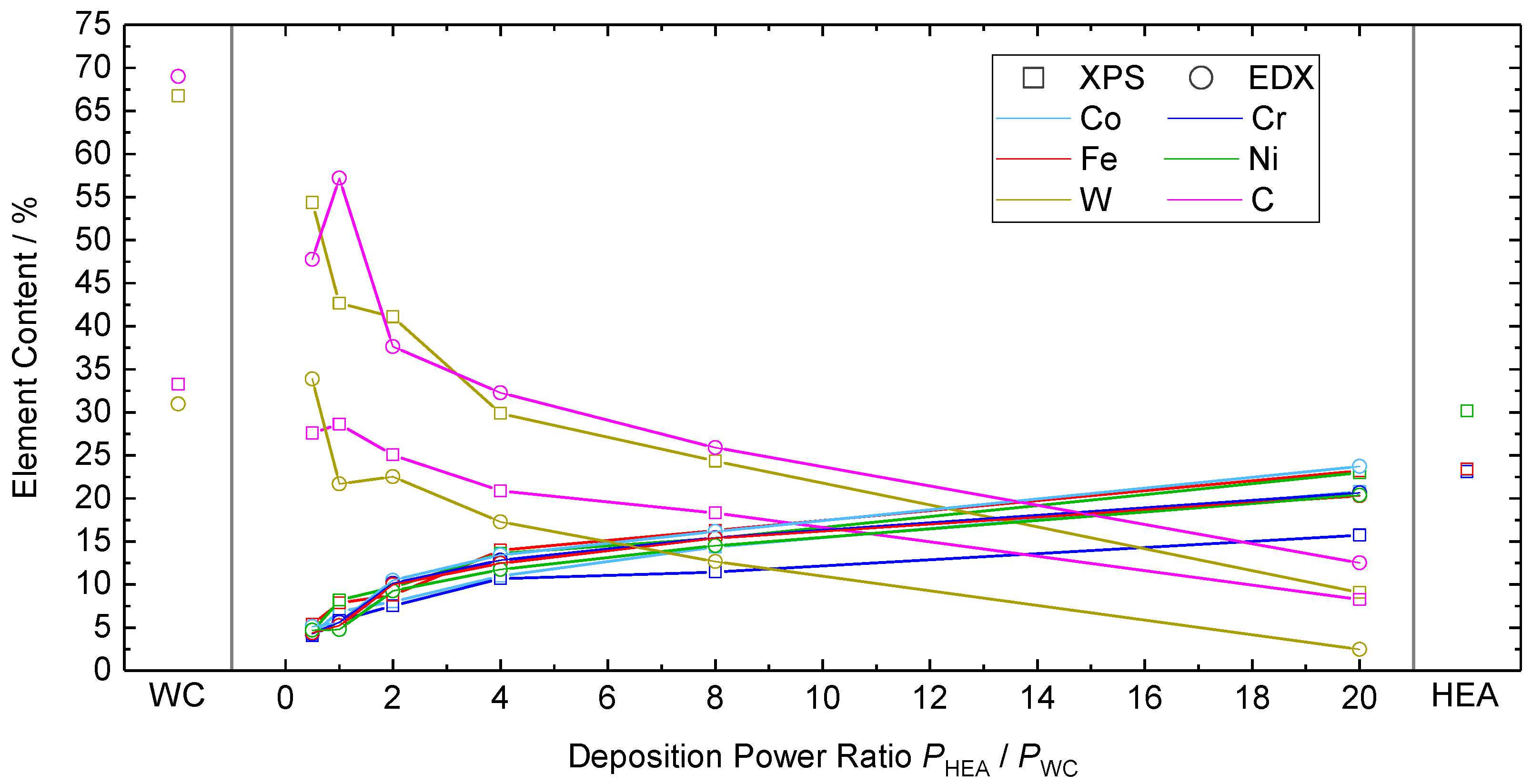
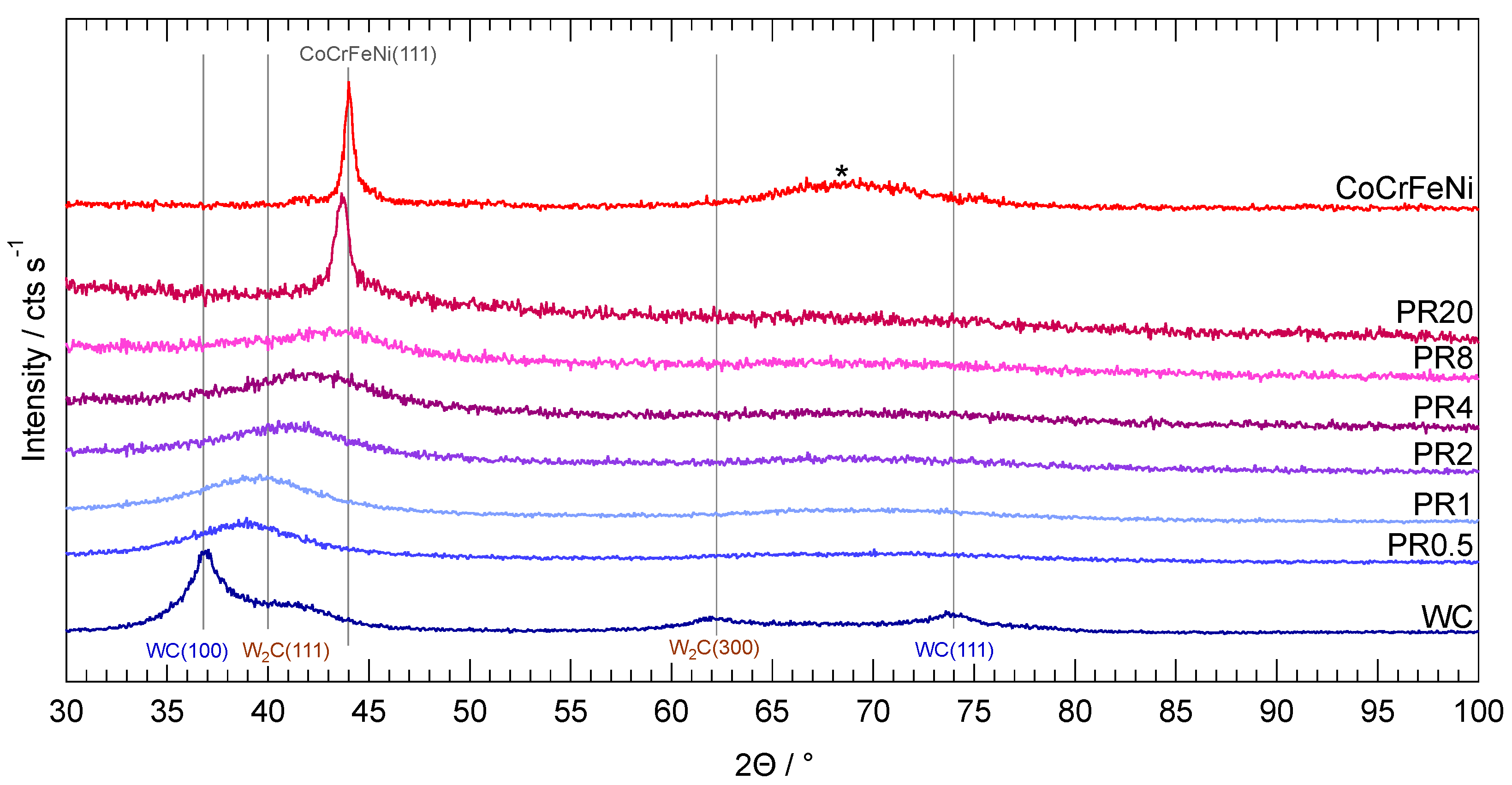
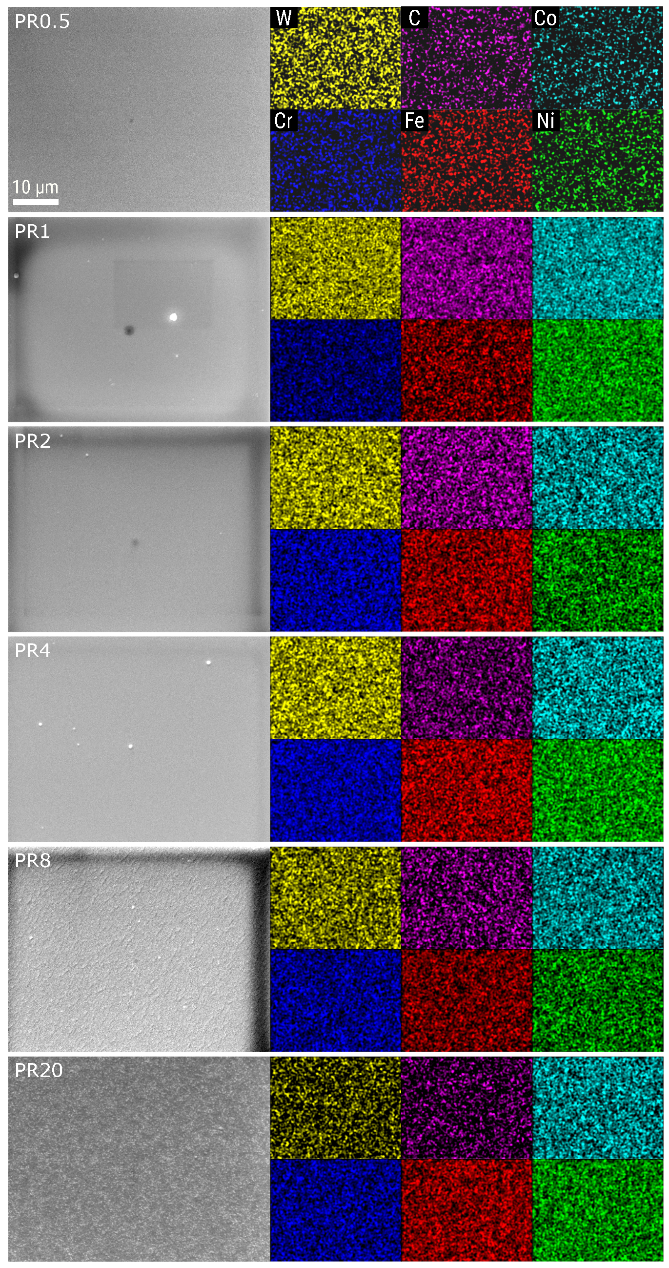
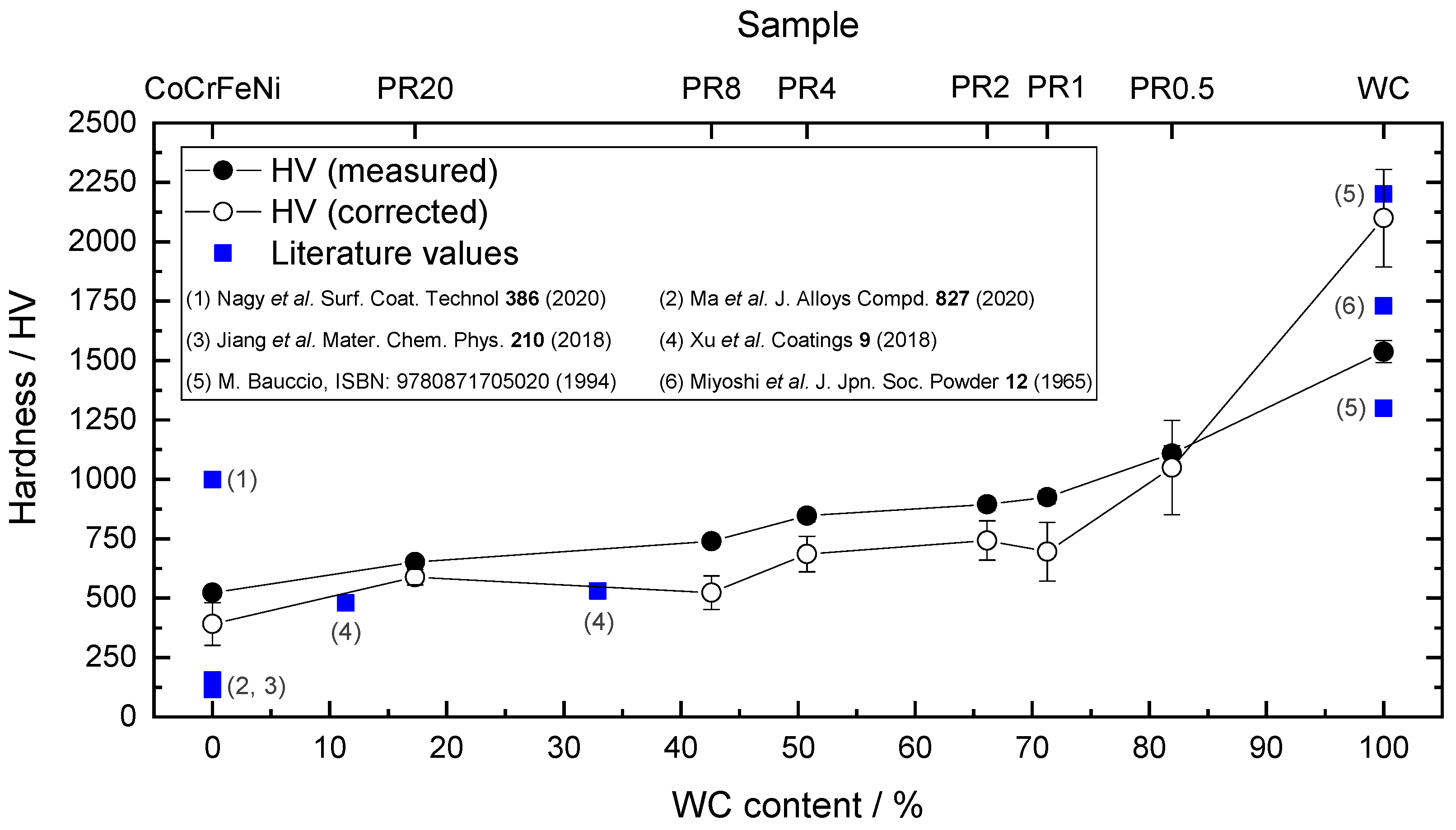
3. Results and Discussion

To verify that the sputtered thin films contain a sufficient quantity of the involved elements, the composition was determined via XPS and EDX measurements. Since XPS is only sensitive to the topmost few atomic layers of a surface, an Ar+ ion bombardment step was performed to prepare clean, unoxidised surfaces prior to the XPS measurement. The stoichiometry was calculated as the intensity ratio of the Co2p1/2, Cr2p3/2, Fe2p3/2, Ni2p3/2, W4f and C1s core levels. For details about the calculation of elemental composition for CoCrFeNi in XPS, see [18]. EDX data were obtained in a setup without the possibility of pre-treatment, so the measured composition was expected to suffer from contaminations. In Figure 1, the element content for Co, Cr, Fe, Ni, C and W is shown as a function of the ratio of sputtering powers used to deposit the thin films. Additionally, results for the pure WC and CoCrFeNi (HEA) samples are shown (see Table 1). It can be seen that the content of the HEA elements is measured to have a similar percentage in all samples independently of the method of determination. Only the Cr content appears to be slightly lower than Co, Fe and Ni in the XPS measurements of the mixed films. This could be due to the fact that Cr has the highest sputter yield among the involved elements, while the yield is rather similar for Co, Fe and Ni (sputter yield calculation based on [23]) and therefore, the Cr content in the surface region is most reduced during the Ar+ bombardment step. A clear discrepancy between nominal and measured element content can be found for the C and W values in nearly all samples and for both methods. The expectation for the W to C ration is 1:1 for all samples which seems to be true only for the XPS measurement of sample PR20. Even for the pure WC film, a significant difference between the measured content of C and W is detected which seems to be inverted for the XPS and EDX measurement. An increased C content in EDX might be partially due to surface contaminations which typically consist of various adventitious carbon components. Furthermore, the C K α emission necessary to determine the stoichiometry in EDX strongly overlaps with various W lines with a much higher intensity. Therefore, a high error in the automated composition calculation in the EDX software (Esprit 1.8.5, Bruker Corporation, Billerica, MA, USA) has to be assumed. Since all samples were cleaned in UHV prior to XPS measurement, the influence of contaminations should be negligible, and indeed, the C percentage is clearly lower compared to EDX. This significantly reduced C content in the XPS measurements suggests a depletion of carbon in the surface region after the cleaning step. Considering the sputter yield again, it is reported that carbon has the lowest atoms/ion sputtering ratio of the present elements [23], and thus, the erosion of carbon during the Ar+ bombardment is expected to be the lowest. Under previous considerations, we have to assume that either the composition of the WC sputter target does not follow the expected 1:1 ratio or that, during the deposition, the C atoms undergo some unexpected effects and do not reach the substrate in a sufficient quantity. From this point, we will discuss the mixed thin films on the basis of a WC content derived as the sum of W and C percentage measured in XPS.
The XRD patterns of the sputter-deposited mixed WC-CoCrFeNi thin films and pure WC and CoCrFeNi references are shown in Figure 2. The substrate was Si(100) for all samples and the strong Si(400) signal at 69.1° was suppressed by applying an offset of 3° to the X-ray source angle Θ . Still a weak Si(400) residual can be seen for the pure CoCrFeNi sample marked by an asterisk. Within the WC measurement, two peaks can be related to the hexagonal P 6 ¯ m2 structure which is the common occurrence of tungsten carbide. Furthermore, there are two additional peaks that have to be assigned to W2C (COD database for Rigaku software, [22]). The formation of the latter was reported for WC films prepared by sputter deposition [24] and seems to be in reasonable accordance with the XPS results, suggesting a tungsten enrichment. A presence of more than 50% of W in the system makes the formation of tungsten rich W2C parallel to WC seem at least possible, although an additional component in the W core levels investigated with XPS has not been observed. For the mixed films, only one rather broad peak is observed in the diffraction patterns. With the increasing CoCrFeNi content, the 2 Θ value of this feature shifted from 38.85° for PR0.5 to 43.05° in sample PR8. While the large half width of these peaks, ranging between (6.7–12.7)°, suggests a structure formed by small polycrystalline grains, the shift to a higher diffraction angle indicates a change in the lattice parameter to smaller values. Taking into account the atomic radius of the elements involved, which is approximately (14–23)% larger for W than for Co, Cr, Fe and Ni [25], it appears comprehensible to observe the transition towards a smaller lattice constant with a reduced WC content. For PR20, a comparably sharp peak can be observed at 43.65°. This value is close to the CoCrFeNi(111) peak detected for the pure HEA thin film at 44.07° and in accordance with the literature [18,26]. According to the stoichiometry previously discussed for PR20, the dominance of the CoCrFeNi structure is assumed. In this sense, we identify the peak detected for PR20 as the (111) reflex of the CoCrFeNi fcc-structure with a slightly increased lattice constant due to the presence of approximately 15% WC.
In order to investigate the elemental distribution, EDX mappings were performed for the mixed thin films. The obtained intensity maps are shown in Figure 3 for the K α excitation lines of C, Co, Cr, Fe and Ni and the L α line of W along with the corresponding secondary electron (SE) image, respectively. The intensity of the EDX signals was equally scaled for each sample to display the best contrast. It can be seen that all elements are evenly distributed in all samples and no hint for separated phases can be observed. From the SE images, a change in morphology can be denoted. On samples PR0.5–PR4, no prominent features can be resolved, even with higher resolution. For PR8, a fine-grained structure is observed with an averaged grain size of ( 20 ± 8 ) nm . Additionally, parallel lamellar structures appear therein with an average normal distance of d x Lam = ( 353 ± 28 ) nm (for an image of the lamellar structure with higher magnification see Figure S1). In the EDX mapping of PR8, however, no similar structure is observable, which indicates an homogeneous stoichiometry even in the lamellae. Sample PR20 shows an enlarged grain size compared to the previously discussed samples, with diameters in the range of (50–260) nm. It is assumed that the formation of bigger grains is due to the increasing CoCrFeNi content. A very similar structure was also reported for surfaces of pure CoCrFeNi prepared by sputter deposition [18].
To determine the hardness of the sputtered thin films, nanoindentation measurements were carried out. For comparison, the pure WC and CoCrFeNi samples discussed before were also analysed. On each sample, 10 measurements were conducted using a force of 5 mN . The averaged hardness values are displayed in Figure 4 as a function of the WC content obtained from XPS (filled black circles). To put the data into the context of existing literature, published hardness values for pure CoCrFeNi [6,12,13], the WC [16,27] and WC-CoCrFeNi mixed specimen [17] are shown as well (blue squares). For thin films, the influence of the substrate on the measured hardness has to be considered, even for low indentation forces. In an attempt to respect this fact, a correction was made as suggested by Jönsson and Hogmark [20] to reduce—or even eliminate—the influence of the substrate on the measured hardness. Accordingly, the film hardness H f can be estimated as
H f = H s + H c H s 2 C t D C 2 ( t D )
where H s is the substrate hardness, H c is the composite hardness—meaning the value directly measured for the thin film/substrate system—t denotes the film thickness and D is the indentation depth. The value C represents a geometry factor that accounts for the difference in the elastic and plastic behaviour of the substrate and coating layer and the geometry of a pyramid-shaped Vickers indenter of the face angle 136°. Assuming a higher hardness for the Si substrate than for the WC-HEA layer, the value C = sin (22°) = 0.1403 was used in this work. Obtained values for the measured composite hardness, calculated film hardness, indentation depth and film thickness of all sputtered samples we discussed are summarised in Table 2.
To obtain the substrate hardness, a pristine Si(100) wafer was probed in the same manner as described for the thin films and a hardness value of H s = ( 1140 ± 56 ) HV was obtained in good agreement with the literature [28,29]. The calculated hardness values for all samples are displayed in Figure 4 as empty circles. The error bars shown correspond to the maximum error approximation. The measured and corrected hardness values both show a monotonic increase with a higher WC content within the realm of the error bars. Although the calculated hardness is 5–25% lower than the directly measured value for the mixed films and the pure CoCrFeNi layer, the similar trend indicates the reasonability of the correction method. On the other hand, the sputtered thin films seem to be thick enough to almost neglect the substrate influence when using a force as low as 5 mN . The hardness obtained for the pure CoCrFeNi specimen in this work fits within the realm of values available in the literature. Most data accessible for CoCrFeNi deal with HEAs fabricated by arc melting methods [12,13,14] and the hardness reported therein is typically 3 (4) times smaller than our directly measured (calculated) values. For samples prepared using sputtering techniques, much higher hardness values of up to 999 HV ( 9.8 GPa ) were recently reported by Nagy et al. [6]. In all of the sources mentioned, the hardness was related to grain size and multiphase formation. In general, smaller grains and fewer parallel existing crystal phases were mentioned as the driving force for hardness enhancement. Although the CoCrFeNi sample discussed in this work exhibited only one peak associated with the fcc (111) structure (see Figure 2), we obtained a comparably big grain size of ( 210 ± 24 ) nm from the SEM images of the sample. Therefore, the hardness obtained in our CoCrFeNi specimen seems to be reasonable. For mixtures of WC and CoCrFeNi fabricated via vacuum hot pressing sintering (VHPS), hardness measurements are available from Xu et al. [17]. For a nominal WC percentage of 10 wt.% ( 11.4 at.%) and 30 wt.% ( 32.9 at.%), the hardness is therein given to be 475 HV and 531 HV , which fits the trend of data obtained in this work. Zhou et al. published hardness values for mechanically spark plasma-sintered alloyed powders of Co, Cr, Fe, Ni and WC [15]. For WC contents in the range of (3–11) at.%, increasing hardness values between (603–768) HV are reported and found to be in reasonable proximity to the values measured in this work. A larger difference between the measured and corrected hardness can be denoted for the sputtered WC reference. In this case, the calculated value differs by 36% from the measurement. Both values are at least still in the realm of literature data ranging from 1300 HV to 2200 HV depending on the WC crystal orientation [16]. Since XRD revealed a mixed formation of various WC and W2C orientations, it appears expedient to find hardness values within this range.

4. Conclusions

The fabrication of evenly mixed CoCrFeNi1−x(WC)x thin films by simultaneous magnetron sputter deposition from two targets was demonstrated. By the variation of the deposition powers for both targets, the WC content of the mixed layers was tuned in the range of (17–82) at.%. The composition was investigated using XPS and EDX. While the percentage of HEA elements Co, Cr, Fe and Ni was in a near-equimolar range for all samples, as confirmed by both methods, larger discrepancies were denoted for the W and C contents. While the stoichiometry obtained from EDX is doubtable, at least for the C content, elemental image mappings reveal an even distribution of all constituents. The SEM images did not show an indication of the separated phases. Single phase formation is further confirmed by X-ray diffraction wherein only one peak was observed for each of the mixed films. A shift of this signal from 43.05° to 38.85° with an increasing WC percentage is observed and interpreted as the transition from a CoCrFeNi dominated fcc structure into a WC-like phase. The Vickers hardness was determined by nanoindentation and showed a monotonic rise from ( 651 ± 20 ) HV to ( 1108 ± 34 ) HV following the increasing WC content. In an attempt to exclude the possible influence of the Si substrate on the hardness measurement, the obtained values were corrected following the suggestion of Jönnson and Hogmark [20]. Furthermore, for the corrected values, a similar trend with slightly reduced hardness, in the range of ( 588 ± 33 HV 1050 ± 199 ) HV was obtained. All hardness data fit well into the scope of the existing literature, which is dominated by reports on the arc melting and sintering processing of HEAs. For the first time, the deposition of evenly mixed thin films of a HEA and WC in a wide range of compositions by magnetron sputtering could be confirmed. The results presented in this work show the potential of co-sputtering to increase mechanical properties of HEAs by adding a variety of additional elements or compounds with high homogeneity and tuneable stoichiometry.

Supplementary Materials

The following supporting information can be downloaded at: https://www.mdpi.com/article/10.3390/coatings12020269/s1, Figure S1: SEM image of sample PR8.

Author Contributions

Conceptualisation, H.S., T.U. and T.L. (Thomas Lindner); methodology, H.S. and T.L. (Thomas Lindner); formal analysis, H.S.; investigation, H.S. and T.L. (Thomas Lindner); resources, T.S., T.L. (Thomas Lampke) and G.W.; writing—original draft preparation, H.S.; writing—review and editing, H.S., T.U., T.L. (Thomas Lindner) and T.S.; visualisation, H.S.; supervision, T.L. (Thomas Lampke), G.W. and T.S.; project administration, T.L. (Thomas Lindner); funding acquisition, T.L. (Thomas Lindner), T.L. (Thomas Lampke), G.W. and T.S. All authors have read and agreed to the published version of the manuscript.

Funding

This study was funded via Sächsische Aufbaubank-Förderbank/SAB-100382175 by the European Social Fund (ESF) and the Free State of Saxony. The publication of this work was funded by the Chemnitz University of Technology.

Informed Consent Statement

Not applicable.

Data Availability Statement

Data available upon request.

Acknowledgments

The authors thank Szilárd Kolozsvári and Wilfried Wallgram and the Plansee company for providing and customising the WC sputter target used within this work and for their helpful support. We thank Christoph Tegenkamp for the possibility to use the SEM/EDX setup and Olav Hellwig for access to the XRD system. The authors thank Marc Pügner for performing the nanoindentation measurements.

Conflicts of Interest

The authors declare no conflict of interest.

References

  1. Yeh, J.W.; Chen, S.K.; Lin, S.J.; Gan, J.Y.; Chin, T.S.; Shun, T.T.; Tsau, C.H.; Chang, S.Y. Nanostructured High-Entropy Alloys with Multiple Principal Elements: Novel Alloy Design Concepts and Outcomes. Adv. Eng. Mater. 2004, 6, 299–303. [Google Scholar] [CrossRef]
  2. Cantor, B.; Chang, I.; Knight, P.; Vincent, A. Microstructural development in equiatomic multicomponent alloys. Mater. Sci. Eng. A 2004, 375–377, 213–218. [Google Scholar] [CrossRef]
  3. Miracle, D.; Senkov, O. A critical review of high entropy alloys and related concepts. Acta Mater. 2017, 122, 448–511. [Google Scholar] [CrossRef] [Green Version]
  4. Li, C.; Li, J.; Zhao, M.; Jiang, Q. Effect of alloying elements on microstructure and properties of multiprincipal elements high-entropy alloys. J. Alloy. Compd. 2009, 475, 752–757. [Google Scholar] [CrossRef]
  5. Kao, Y.F.; Chen, T.J.; Chen, S.K.; Yeh, J.W. Microstructure and mechanical property of as-cast, -homogenized, and -deformed AlxCoCrFeNi (0 ≤ x ≤ 2) high-entropy alloys. J. Alloy. Compd. 2009, 488, 57–64. [Google Scholar] [CrossRef]
  6. Nagy, P.; Rohbeck, N.; Roussely, G.; Sortais, P.; Lábár, J.; Gubicza, J.; Michler, J.; Pethö, L. Processing and characterization of a multibeam sputtered nanocrystalline CoCrFeNi high-entropy alloy film. Surf. Coat. Technol. 2020, 386, 125465. [Google Scholar] [CrossRef]
  7. Shi, Y.; Yang, B.; Liaw, P. Corrosion-Resistant High-Entropy Alloys: A Review. Metals 2017, 7, 43. [Google Scholar] [CrossRef] [Green Version]
  8. Niu, Z.; Xu, J.; Wang, T.; Wang, N.; Han, Z.; Wang, Y. Microstructure, mechanical properties and corrosion resistance of CoCrFeNiW (x = 0, 0.2, 0.5) high entropy alloys. Intermetallics 2019, 112, 106550. [Google Scholar] [CrossRef]
  9. Fazakas, E.; Varga, B.; Geantă, V.; Berecz, T.; Jenei, P.; Voiculescu, I.; Coșniță, M.; Ștefănoiu, R. Microstructure, Thermal, and Corrosion Behavior of the AlAgCuNiSnTi Equiatomic Multicomponent Alloy. Materials 2019, 12, 926. [Google Scholar] [CrossRef] [Green Version]
  10. Gludovatz, B.; Hohenwarter, A.; Catoor, D.; Chang, E.H.; George, E.P.; Ritchie, R.O. A fracture-resistant high-entropy alloy for cryogenic applications. Science 2014, 345, 1153–1158. [Google Scholar] [CrossRef] [Green Version]
  11. Wu, J.M.; Lin, S.J.; Yeh, J.W.; Chen, S.K.; Huang, Y.S.; Chen, H.C. Adhesive wear behavior of AlxCoCrCuFeNi high-entropy alloys as a function of aluminum content. Wear 2006, 261, 513–519. [Google Scholar] [CrossRef] [Green Version]
  12. Ma, H.; Shek, C.H. Effects of Hf on the microstructure and mechanical properties of CoCrFeNi high entropy alloy. J. Alloy. Compd. 2020, 827, 154159. [Google Scholar] [CrossRef]
  13. Jiang, H.; Han, K.; Qiao, D.; Lu, Y.; Cao, Z.; Li, T. Effects of Ta addition on the microstructures and mechanical properties of CoCrFeNi high entropy alloy. Mater. Chem. Phys. 2018, 210, 43–48. [Google Scholar] [CrossRef]
  14. Huang, T.; Jiang, L.; Zhang, C.; Jiang, H.; Lu, Y.; Li, T. Effect of carbon addition on the microstructure and mechanical properties of CoCrFeNi high entropy alloy. Sci. China Technol. Sci. 2017, 61, 117–123. [Google Scholar] [CrossRef]
  15. Zhou, R.; Chen, G.; Liu, B.; Wang, J.; Han, L.; Liu, Y. Microstructures and wear behaviour of (FeCoCrNi)1−x(WC)x high entropy alloy composites. Int. J. Refract. Met. Hard Mater. 2018, 75, 56–62. [Google Scholar] [CrossRef]
  16. Bauccio, M. ASM Engineering Materials Reference Book, 2nd ed.; Taylor & Francis: London, UK, 1994. [Google Scholar]
  17. Xu, J.; Wang, S.; Shang, C.; Huang, S.; Wang, Y. Microstructure and Properties of CoCrFeNi(WC) High-Entropy Alloy Coatings Prepared Using Mechanical Alloying and Hot Pressing Sintering. Coatings 2018, 9, 16. [Google Scholar] [CrossRef] [Green Version]
  18. Schwarz, H.; Uhlig, T.; Rösch, N.; Lindner, T.; Ganss, F.; Hellwig, O.; Lampke, T.; Wagner, G.; Seyller, T. CoCrFeNi High-Entropy Alloy Thin Films Synthesised by Magnetron Sputter Deposition from Spark Plasma Sintered Targets. Coatings 2021, 11, 468. [Google Scholar] [CrossRef]
  19. Luo, D.; Zhou, Q.; Ye, W.; Ren, Y.; Greiner, C.; He, Y.; Wang, H. Design and Characterization of Self-Lubricating Refractory High Entropy Alloy-Based Multilayered Films. ACS Appl. Mater. Interfaces 2021, 13, 55712–55725. [Google Scholar] [CrossRef]
  20. Jönsson, B.; Hogmark, S. Hardness measurements of thin films. Thin Solid Film. 1984, 114, 257–269. [Google Scholar] [CrossRef]
  21. Horcas, I.; Fernández, R.; Gómez-Rodríguez, J.M.; Colchero, J.; Gómez-Herrero, J.; Baro, A.M. WSXM: A software for scanning probe microscopy and a tool for nanotechnology. Rev. Sci. Instrum. 2007, 78, 013705. [Google Scholar] [CrossRef]
  22. Gražulis, S.; Chateigner, D.; Downs, R.T.; Yokochi, A.F.T.; Quirós, M.; Lutterotti, L.; Manakova, E.; Butkus, J.; Moeck, P.; Bail, A.L. Crystallography Open Database – an open-access collection of crystal structures. J. Appl. Crystallogr. 2009, 42, 726–729. [Google Scholar] [CrossRef] [PubMed]
  23. Matsunami, N.; Yamamura, Y.; Itikawa, Y.; Itoh, N.; Kazumata, Y.; Miyagawa, S.; Morita, K.; Shimizu, R.; Tawara, H. Energy dependence of the ion-induced sputtering yields of monatomic solids. At. Data Nucl. Data Tables 1984, 31, 1–80. [Google Scholar] [CrossRef]
  24. Fuchs, K.; Rödhammer, P.; Bertel, E.; Netzer, F.; Gornik, E. Reactive and non-reactive high rate sputter deposition of Tungsten carbide. Thin Solid Film. 1987, 151, 383–395. [Google Scholar] [CrossRef]
  25. Clementi, E.; Raimondi, D.L.; Reinhardt, W.P. Atomic Screening Constants from SCF Functions. II. Atoms with 37 to 86 Electrons. J. Chem. Phys. 1967, 47, 1300–1307. [Google Scholar] [CrossRef]
  26. Shi, Y.; Yang, B.; Rack, P.D.; Guo, S.; Liaw, P.K.; Zhao, Y. High-throughput synthesis and corrosion behavior of sputter-deposited nanocrystalline Al (CoCrFeNi)100- combinatorial high-entropy alloys. Mater. Des. 2020, 195, 109018. [Google Scholar] [CrossRef]
  27. Miyoshi, A.; Hara, A. High Temperature Hardness of WC, TiC, TaC, NbC and Their Mixed Carbides. J. Jpn. Soc. Powder Powder Metall. 1965, 12, 78–84. [Google Scholar] [CrossRef]
  28. Beegan, D.; Chowdhury, S.; Laugier, M. The nanoindentation behaviour of hard and soft films on silicon substrates. Thin Solid Film. 2004, 466, 167–174. [Google Scholar] [CrossRef]
  29. Walls, M.G.; Chaudhri, M.M.; Tang, T.B. STM profilometry of low-load Vickers indentations in a silicon crystal. J. Phys. Appl. Phys. 1992, 25, 500–507. [Google Scholar] [CrossRef]
Figure 1. Elemental composition for pure CoCrFeNi (HEA), WC and mixed thin films obtained from XPS (□) and EDX (◯) measurements.
Coatings 12 00269 g001
Figure 2. X-ray diffraction patterns of the WC-CoCrFeNi mixed thin films and pure WC and CoCrFeNi for comparison. Assigned signals are labelled according to the Crystallographic Open Database (see, e.g., [22]). The asterisk marks the residual of the suppressed Si(400) signal from the substrate.
Coatings 12 00269 g002
Figure 3. EDX maps and corresponding SE images for the WC-CoCrFeNi mixed thin films prepared by magnetron co-sputtering. The mapped intensities for C, Co, Cr, Fe and Ni belong to the respective K α radiation lines; for W, the L α intensity map is shown.
Coatings 12 00269 g003
Figure 4. Hardness values of the sputtered thin films as obtained from nanoindentation (black filled circles) and after thin film correction according to [20] (empty circles) as a function of the WC content determined by XPS. Literature values from [6,12,13,16,17,27] are presented for comparison (blue squares). The error bars correspond to the maximum error approximation.
Coatings 12 00269 g004
Table 1. Deposition parameters for the discussed samples (the time values refer to the actual deposition time excluding presputtering).
SampleCoCrFeNi Target
Power P HEA (W)
WC Target
Power P WC (W)
Time (min)Film Thickness (nm)
CoCrFeNi200-15201
PR0.510020015197
PR120020015305
PR240020015411
PR480020015443
PR880010015481
PR2010005015820
WC-20015209
Table 2. Hardness values H c as measured via nanoindentation (black circles in Figure 4) and after the thin film correction from Jönnson and Hogmark [20] H f (empty circles in Figure 4). The indentation depth D and film thickness t necessary to calculate H f is given for the sake of completeness.
Sample H c (HV) H f (HV)Indentation Depth D (nm)Thickness t (nm)
WC 1538 ± 47 2099 ± 206 125 ± 2 209
PR0.5 1108 ± 34 1050 ± 199 142 ± 2 197
PR1 925 ± 28 696 ± 123 152 ± 2 305
PR2 895 ± 27 742 ± 84 152 ± 2 411
PR4 847 ± 26 686 ± 76 154 ± 2 443
PR8 740 ± 23 523 ± 71 166 ± 2 481
PR20 651 ± 20 588 ± 33 174 ± 2 820
CoCrFeNi 523 ± 16 391 ± 90 190 ± 2 201
Publisher’s Note: MDPI stays neutral with regard to jurisdictional claims in published maps and institutional affiliations.

