1. Introduction
As a part of European policy, the strategy for the energy sector 20-20-20, has been introduced—targeted to the end of 2020. It has been stated that at least 20% of greenhouse gas emission would be cut (compared to 1990), 20% of all energy produced in EU would be from renewable sources, and energy efficiency would be improved by 20% [
1]. One of the ways to lower fossil fuel consumption is to produce electricity and energy from renewable sources—in case of Czechia, mainly out of biomass. According to Eurostat data, in 2018 nearly 60% of non-fossil fuel was in the form of biofuel [
2]. Predictions indicate that biomass will be the dominant form of renewable energy also in a near future, especially because of the rapid increase of biomass harvest (mainly wood) in recent years compared to the period 2011–2015. This increase is about 50% in total and is caused by growing wood markets and, in some member states, by bark beetle outbreaks [
3]. Therefore, more and more biomass together with other alternative types of fuels (enhanced recycled fuel, waste, etc.) is burned in boilers and, due to the presence of very reactive elements in this kind of fuel (chlorine, sulfur), there is a higher risk of boiler corrosion compared to that linked to coal combustion.
Several studies have investigated how firing and/or co-firing of biomass can enhance the corrosive aggressivity of flue gas—especially due to a high content of sulfur and chlorine in raw fuel. A high chlorine content in biomass can be devastating for heat-exchanging surfaces in plants combusting straw, and conventional boiler tube materials cannot be used in such case [
4]. In the case of wooden chips, the flue gas is not corrosive as that from straw or grass/hay but, still, the corrosion rate is much higher than that in coal-fired powerplants using ferritic/pearlitic steels up to 550 °C or austenitic steels in supercritical boiler units. This can be particularly problematic for power/heating plants with coal-fired boilers that are switching to wooden chips fuel without major investments or enhancements in superheater materials. Generally, in in this case, it is better to use austenitic or nickel-based alloys, but the investments cost is high. Another viable option is to use alloyed claddings or thermally sprayed coatings, which can greatly improve the corrosion resistance of conventional materials in chlorine-containing environments [
5].
In this study here presented, various thermally sprayed coatings were tested in an atmosphere containing chlorine/hydrogen chloride, simulating the biomass burner flue gas, which usually contains Cl
2/HCl as the most corrosive species [
6]. This laboratory atmosphere was prepared after determining the flue gas chemical composition in a particular coal-fired fluidizing bed boiler (in The Czech Republic) that had been adapted to biomass fuel and presented severe corrosion damages after several months of straw/woodchips burning on the windward side of the superheater.
2. Materials and Methods
2.1. Substrate Materials
Five different metallic coatings and two steel materials, as a reference, were tested in this work. One of them was ferritic/pearlitic steel 16Mo3, which is widely used as a superheater material for coal-fired boilers up to 550 °C. This steel is also used in waste incineration plants or biomass boilers at lower temperatures but, often there are certain corrosion problems as aggressive deposits are formed on tubes’ surfaces during the operational time [
7]. The second reference material was austenitic high alloyed steel AISI 310, which can be used as a replacement for boiler tubes that switched from coal to biomass or waste fuel, as it has significantly higher thermal and corrosion resistance compared to standard ferritic/pearlitic or martensitic boiler tubes, e.g., 16Mo3, P91, T23, and others [
8]. The test temperatures for materials and coatings were 500 and 600 °C. Data about the chemical composition of tested coatings and base materials are shown in
Table 1.
2.2. Thermally Sprayed Coatings
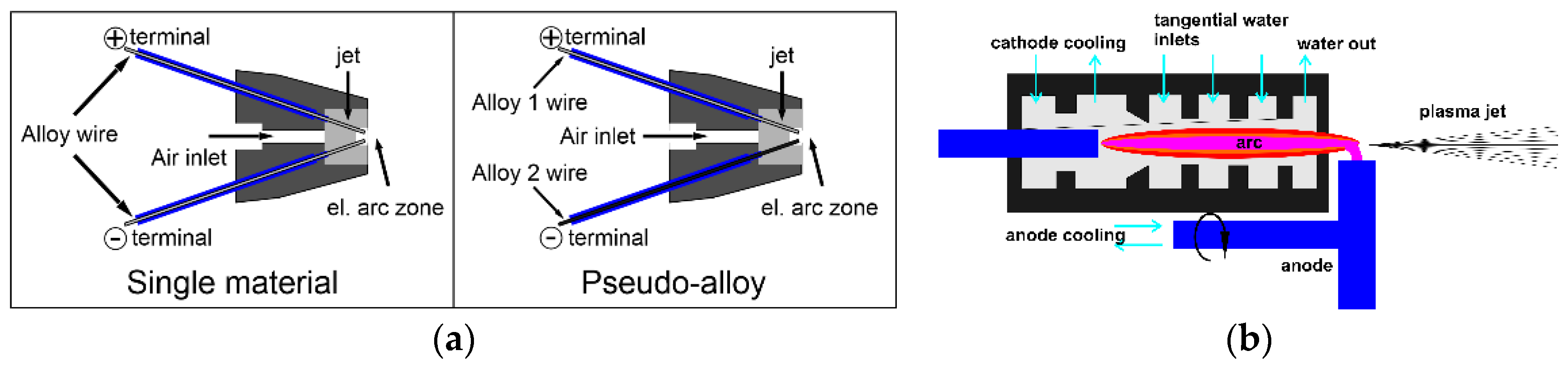
Three different technologies of thermal spray—TWAS, HVOF, and water-stabilized plasma—were compared and tested in this work. Three coatings were prepared by the standard TWAS (thin wire arc spray) method. This technology is relatively easy and can produce a high amount of coating per hour (up to 80 kg/h). Other advantages are a relatively low price, mobility, and easy instrumentation. During TWAS, the coating material is fed into the gun in the form of two wires. An electric arc is generated between the ends of the wires, whose energy is used to melt the material. The acceleration of the particles towards the substrate is provided by compressed air. The temperature of the arc is around 4000 °C, but due to the cold carrier medium, it is reduced before the particles hit the substrate. The particle impact velocity on the substrate is 100 to 130 m/s. Two of the three TWAS coatings were prepared from wires of the same alloys (the anode and cathode were made of the same additive material)—in the first case, it was Alloy 625, and in the second case, it was 45CT material. The third one was made of a so-called pseudo-alloy [
9], which was prepared by feeding a spraying jet with two different wires which were simultaneously melted in an electric arc, forming a mixture of the two alloys—schemes are shown in
Figure 1a. The anode was made of an alloy 625 wire, while the cathode consisted of a NiCrMoB wire. In addition, in this case, a base layer consisting of pure nickel was used to ensure good adhesion of the coating to the base material.
The fourth tested coating consisted of K50 alloy (a nickel-based material alloyed with chromium, silicone, and boron) prepared by a hybrid water–gas DC Arc plasma torch. A schematic image of the plasma torch with Gerdien arc is shown in
Figure 1b. The chamber is divided into several sections where water is injected tangentially, and a water vortex is created. The inner diameter of the vortex is determined by the diameter of the holes in the segments between the sections. Water is exhausted at two positions at the ends of the arc chamber. A consumable cathode is created by a graphite rod, and the anode, consisting of a copper disc with internal cooling, is located outside the arc chamber, downstream of the exit nozzle. The anode disc rotates to reduce the electrode erosion in the plasma stream. The coating material in this case was in the form of a fine powder (20–40 μm) that was filled directly into the plasma arc [
10].
Last, the fifth thermally sprayed coating was made using the HP/HVOF (High-Pressure/High-Velocity Oxygen Fuel) technology using Amperit 469.088 (CoCrAlYTaCSi) with particle size distribution for HP/HVOF of 20–53 μm. The precursor powder for this coating was fed directly into the flame stream at a temperature of about 5000 °C with a flue gas velocity of 500–1200 m/s. The burner used pure oxygen and kerosene. The chemical composition of the wires used for TWAS of a particular coating preparation as well as of the powders used for plasma and HVOF layers are shown in
Table 1. Optical light micrographs of all thermally sprayed coatings before testing are shown in
Figure 2.
2.3. Testing Samples
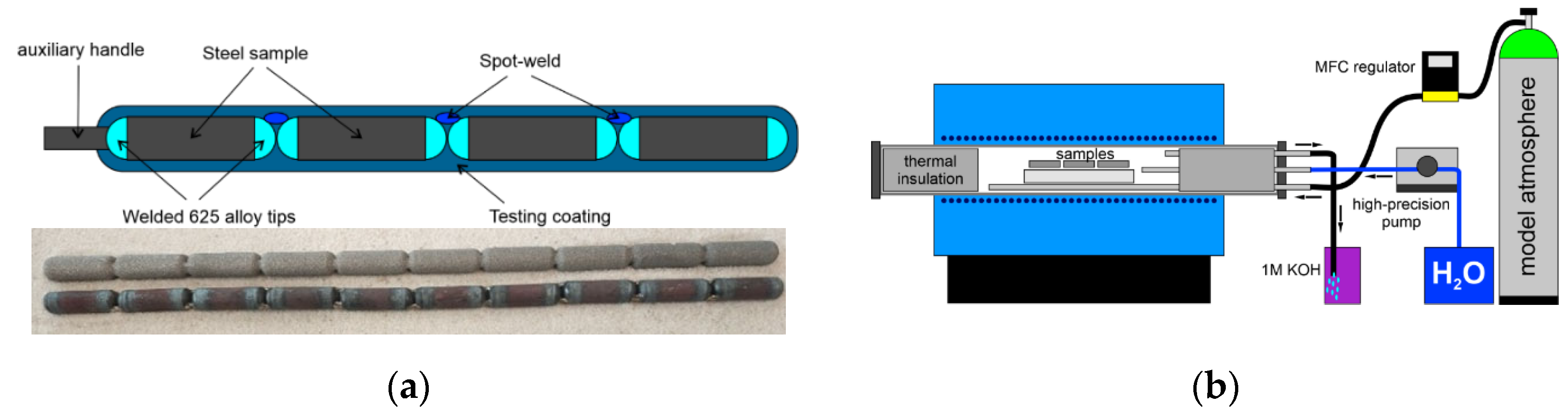
The high-temperature corrosion resistance of the tested thermally spray coatings was tested in a gas-tight furnace; each specimen was in its own alumina vessel. All coatings were prepared using two base materials—ferritic/pearlitic 16Mo3 steel and austenitic steel AISI 310—in the form of 30 mm-long cylindrical coupons. Since it is extremely complicated and sometimes impossible to spray each testing sample separately, it was necessary to make a rod out of individual samples, which was coated and then cut into pieces—
Figure 3a. Because of this procedure, the samples after cutting were left without coating on their sides; this could cause severe corrosion during the test and spallation of sprayed coating, especially in the case of the 16Mo3 substrate material. For this reason, individual specimens (28 mm-long cylinders) were provided with Inconel 625 tips (TIG welding) and then were welded together, forming whole rods of 10 samples. Subsequently, one of the tested spray coating methods was applied. After spraying, the bars were cut again right in the spot welds, and the resulting sample was thus protected on all its sides (either by the coating itself or by welded material on the sides).
2.4. Exposure Tests
High-temperature corrosion tests were carried out in a gas-tight furnace with a cylindrical alumina muffle. All samples were placed into a small ceramic vessel and packed together into a set that was exposed in a model biomass flue gas testing atmosphere which had been controlled by a mass flow controller/regulator; the flow rate was set to 100 mL/min. The composition of the testing gas is shown in
Table 2—selected as a compromise between real flue gas measurements and literature data [
11,
12]. Water was supplied to the flue gas by a high-precision pump with a microinjection system—liquid water (1 mL/min) was added to the furnace, and evaporation occurred directly inside the ceramic muffle—
Figure 3b. The remaining atmosphere exiting the furnace was neutralized by a potassium hydroxide solution.
In total, five samples of each type of coating and base material were tested in the model flue gas atmosphere at 500 and 600 °C—the most temperature range for boilers in the Czech Republic that are being considered for biomass burning. After 5000 h of exposure, one of the tested specimens was removed for metallographic analysis. After the exposure tests, the corrosion resistance of all sprayed coatings and substrate materials was evaluated by gravimetry, light metallography, and other methods.
3. Results
The determination or comparison of the corrosion rate of the individual tested materials was carried out by gravimetric analysis, measuring the weight changes of the samples during exposure to the model atmosphere. In this case, the level of oxidation was determined by measuring weight gains—it was impossible to determine weight losses, as the oxidic layer on the surface of the sprayed coatings could not be selectively removed, chemically or physically.
3.1. Gravimetric Results
The results of long-term exposure at 500 °C in a model atmosphere containing hydrogen chloride are shown in
Table 3. All gravimetric data were calculated in grams per square meter (g/m
2). In the right column of
Table 3, a mini graph shows the trend of weight growth of the tested materials/coatings. Most of the coated samples showed a slow parabolical trend of corrosion; especially, after the first 200 h of exposure, weight gains were substantially high. This essentially corresponds to a slow parabolic law, where the oxidation rate is controlled by the diffusion rate, which is reduced by the growth of oxides on the surface. However, in the case of thermally sprayed coatings, the initial rate of oxidation was accelerated by the large surface area of the samples, which were usually very coarse, and by their porosity [
13,
14].
However, these weight changes plummeted in time (after a rapid oxidation of the coarse surface layer), and further corrosion changes were extremely limited. For example, in the case of the K50 coating made using the plasma torch, the initial weight growth was very large, but approximately after the first 500 h in model atmosphere at 500 °C, it almost stopped; afterwards, there were practically no weight changes.
Technically, the weight gains after 5000 h at 500 °C (in g/m
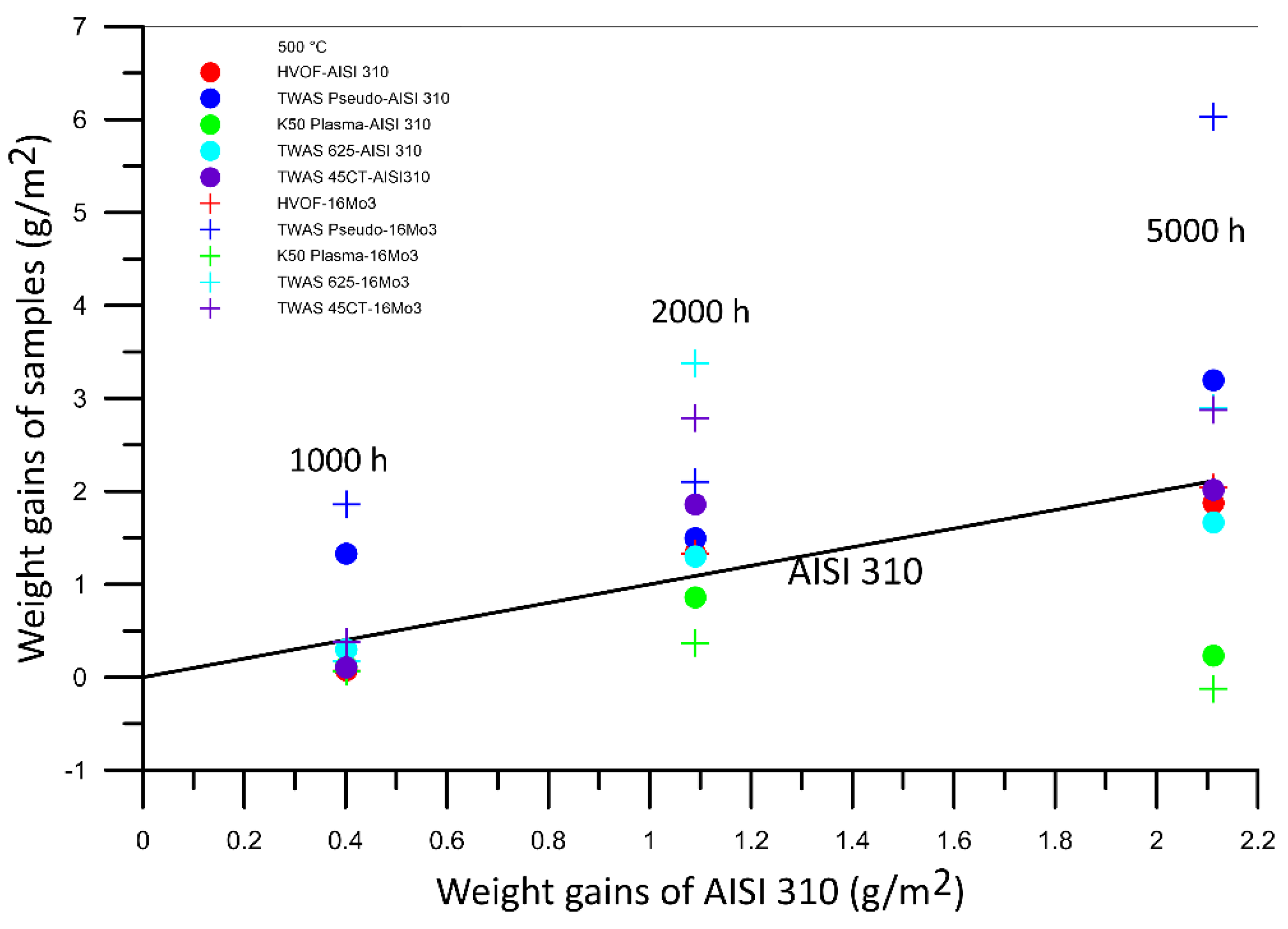
2) in the high-temperature test were higher for any type of coating than for austenitic steel AISI 310. The best behavior was shown by samples treated with HVOF coating, which had an exceptionally fine surface; their corrosion rates equaled that of the base material. However, since the surface of the coated sample was much larger, there will always be rapid oxidation and weight gain at the initial phase of exposure. The graph in
Figure 4 shows the dependency of AISI 310 weight gains and of weight gains of other coated samples—the initial weight for gravimetric analysis was considered that after 500 h of exposure. In this graph, the black line indicates the weight gains of austenitic steel AISI 310. The samples situated above this line showed higher corrosion rates than this steel. We can see that a good portion of the tested materials showed a similar or better corrosion behavior in chlorine-containing atmosphere at 500 °C than high alloyed austenitic steel AISI 310. Better coatings corrosion resistance was observed for samples with the AISI 310 substrate. Every sample of the tested coatings showed better corrosion/gravimetric results than low alloyed boiler steel 16Mo3—if we do not consider the initial phase of rapid oxidation that occurred in the first 200 or 500 h of high-temperature oxidation.
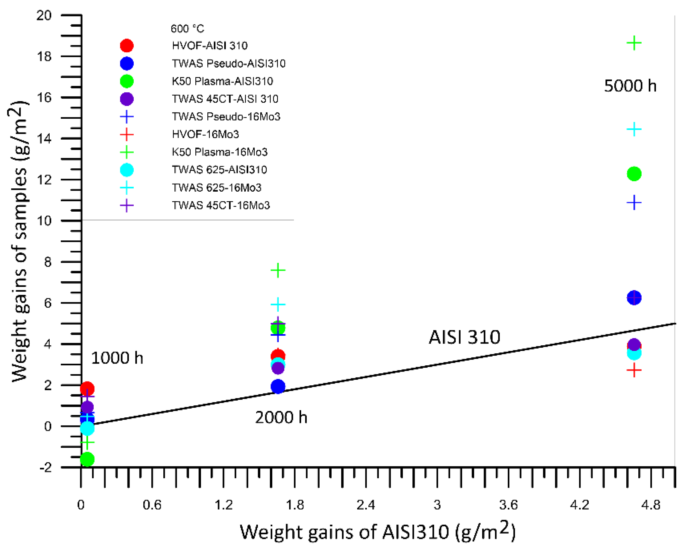
Table 4 presents the gravimetric data of all tested sprayed coatings and base materials after exposure in model atmosphere containing chlorine at 600 °C. In this case, the measured weight gains were generally higher compared to those measured in the experiments carried out at 500 °C. Especially, low alloyed steel 16Mo3 showed an extremely high corrosion rate—which was also the initial presumption, as these materials are not a good choice for application in boilers under these conditions (biomass fuel) without any additional protection. As observed before, the vast majority of the tested coatings suffered rapid oxidation (weight gains) during the first 200 h of the experiment. After approximately 500 h, these weight changes rapidly declined as before. The corrosion rate was certainly influenced by the coating surface profile: the finest surface of HVOF coating showed better corrosion behavior than the base material AISI 310, while the K50 Plasma layer with the coarsest surface suffered rapid oxidation at the beginning of the experiment.
During the experiment at 600 °C, all thermally sprayed coatings showed significantly better corrosion resistance than 16Mo3 steel.
Figure 5 shows a comparison between the weight gains of the samples and of AISI 310 steel. As before, all materials under the black line showed better gravimetric results than this austenitic steel, when not considering the first 500 h of oxidation, and the gravimetry analysis started after 500 h of exposure. Overall, all weight changes were similar, and except for 16Mo3 steel, no tested samples exhibited severe corrosion damage.
3.2. Metallographic Results
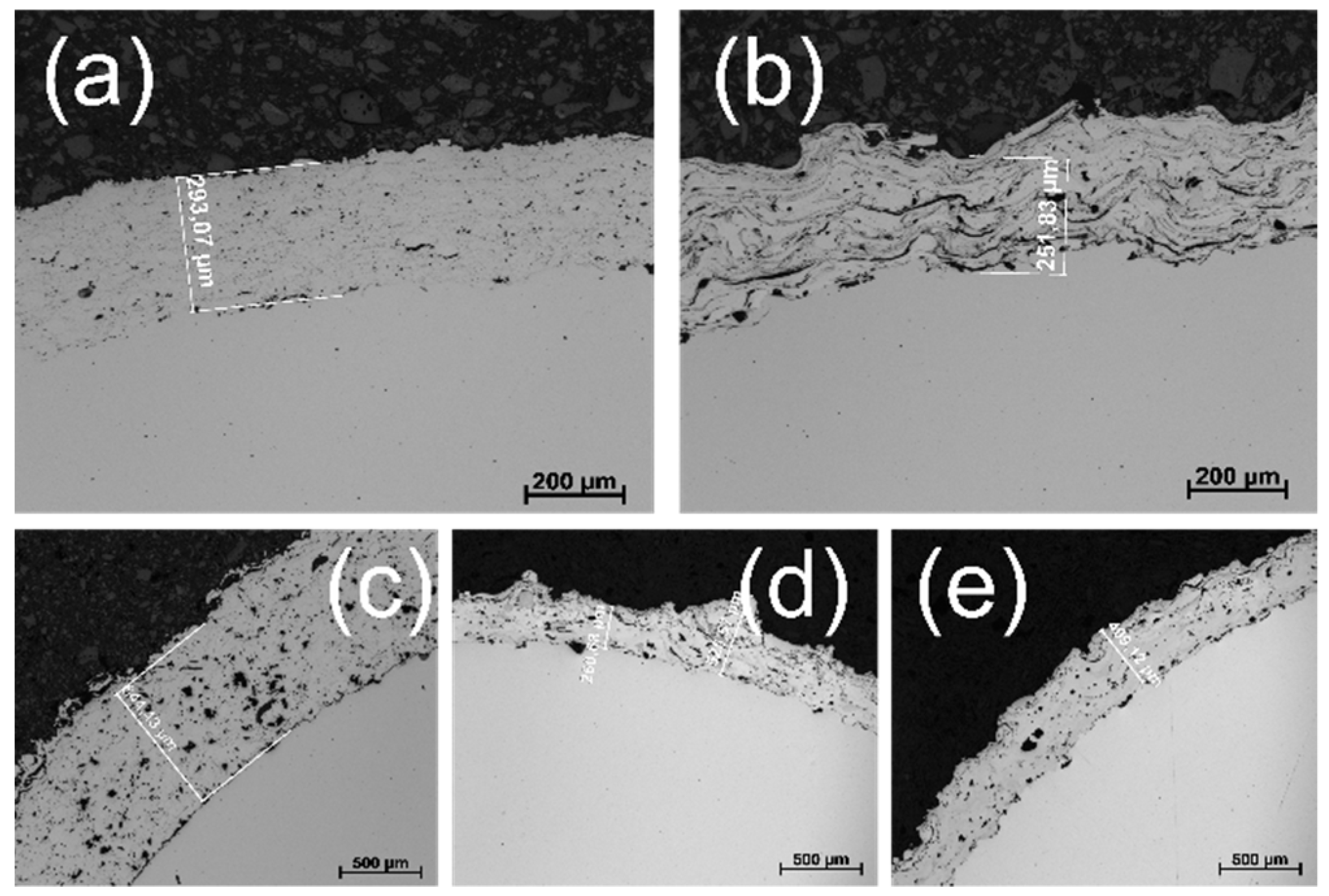
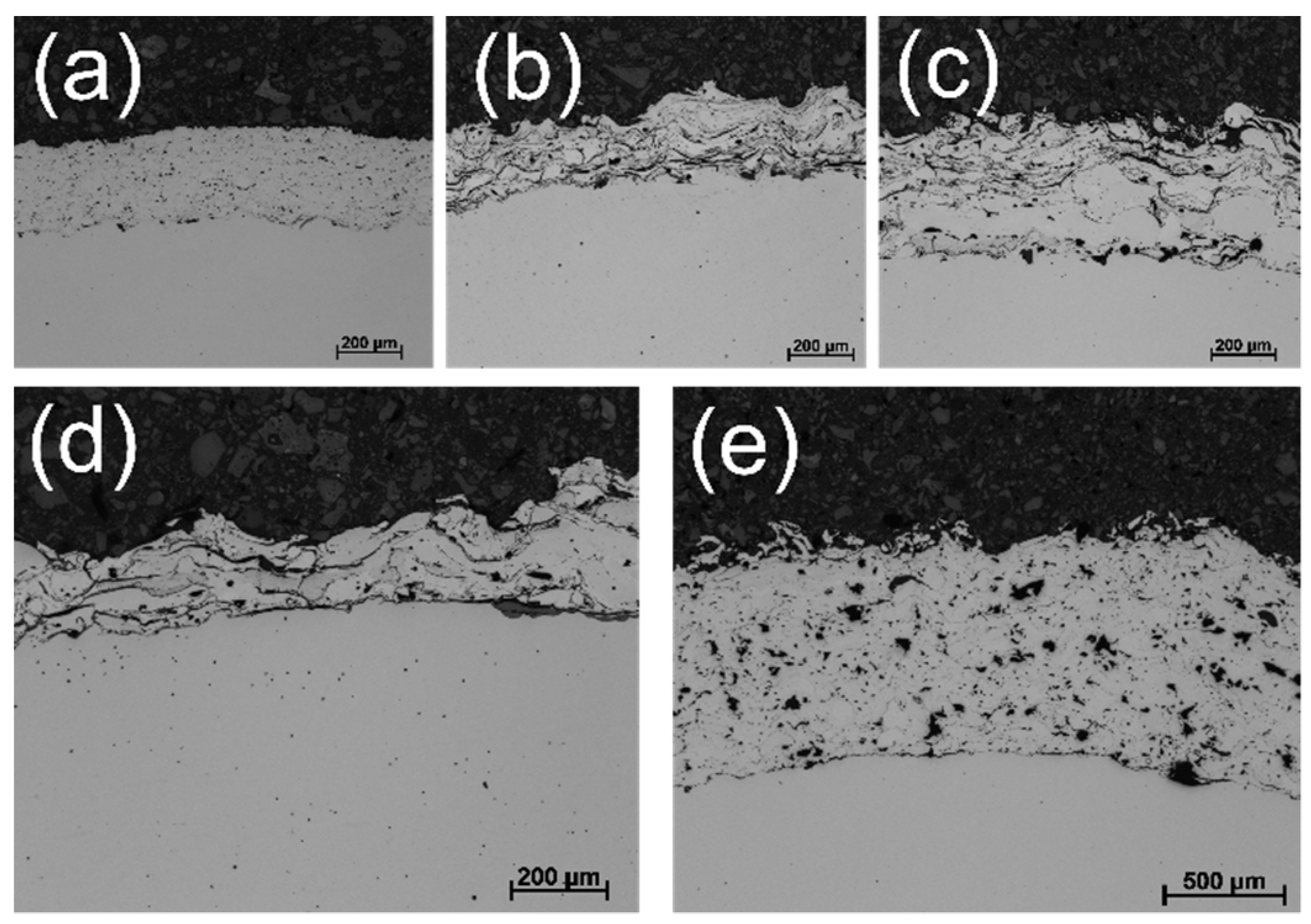
Figure 6 shows light microscopy photos of the coating samples after exposure at 500 °C in a model atmosphere containing hydrogen chloride (5000 h), in this case, samples with a base material consisting of 16Mo3. Compared with the exposed coatings in the initial condition, no significant corrosion problems occurred during the exposure, and the structure of the individual coatings was virtually identical to the initial one. Of course, the most compact surface with practically no oxidation was observed for the sample coated by the HVOF technology. Even in the plasma spraying coating case (e in
Figure 6), where higher porosity or higher number of oxidized particles were expected in the initial state, the structure was relatively compact in a cross section, and no defects or cracks in the coating structure were observed. No delamination was observed in the experiment at 500 °C, neither on AISI 310 austenitic steel substrate material nor on 16Mo3 ferritic steel base material.
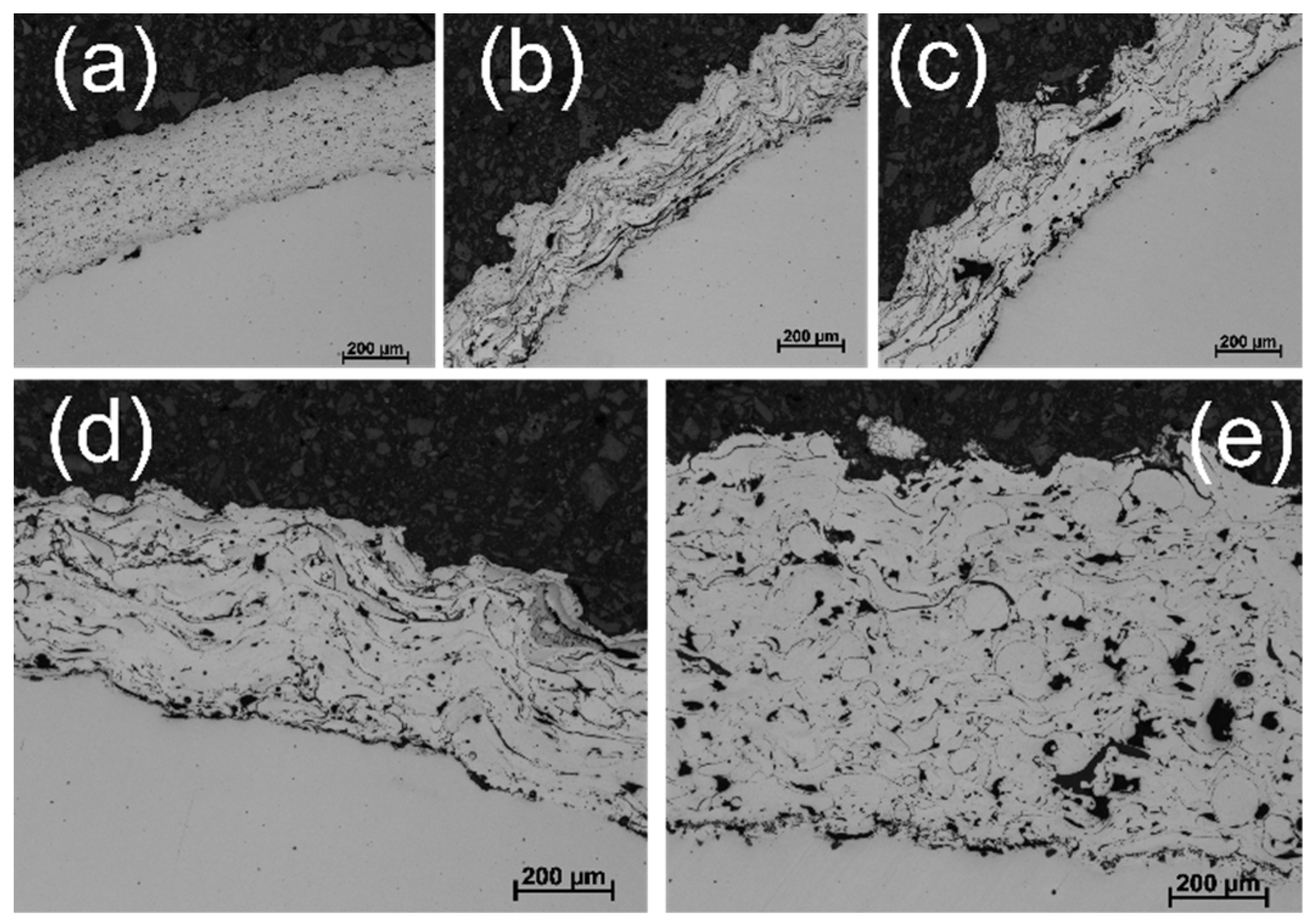
Similar results were obtained after exposure of the coatings at 600 °C in an environment containing hydrogen chloride, as shown in
Figure 7, which presents the results for the hot-sprayed samples on 16Mo3 steel substrate—the samples with AISI 310 austenitic steel were similar or better after exposure under the same conditions. Again, small pores in the structure of the coatings (especially, plasma) were observed, but so far without signs of penetration of the corrosive atmosphere to the base material (16Mo3), which would otherwise highly oxidize in the given environment, and its weight gains would be much higher than those of samples of individual protective coatings. In this respect, the best sample was again the HVOF-prepared coating, which was virtually free of oxidized particles, and its overall structure was also free of signs of corrosion.
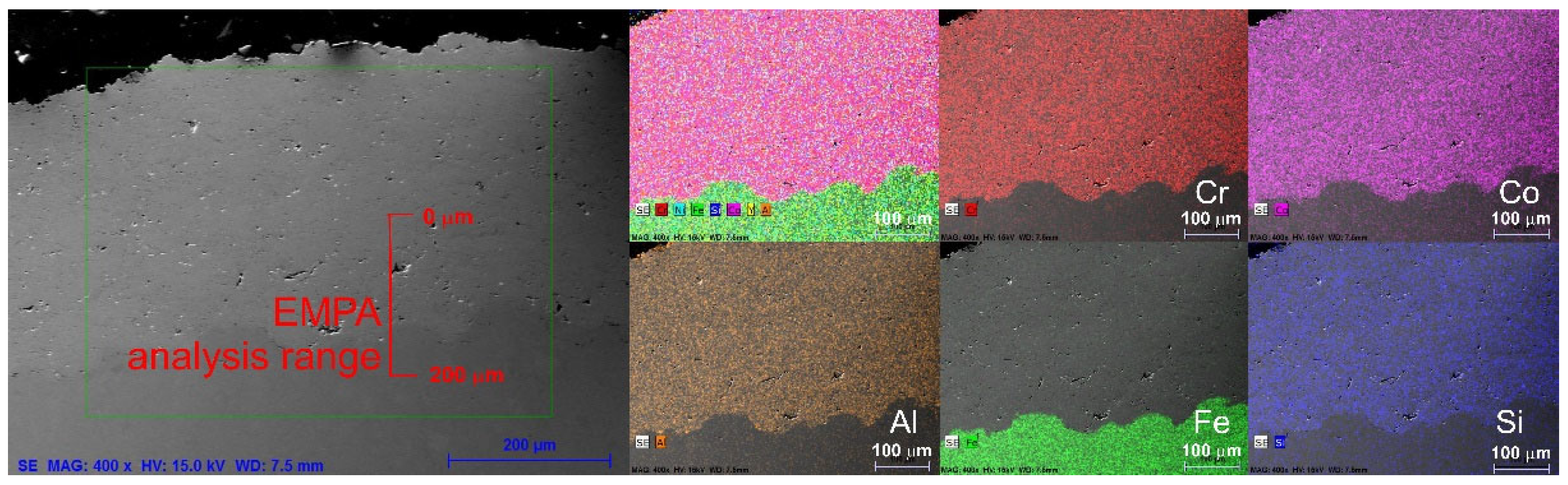
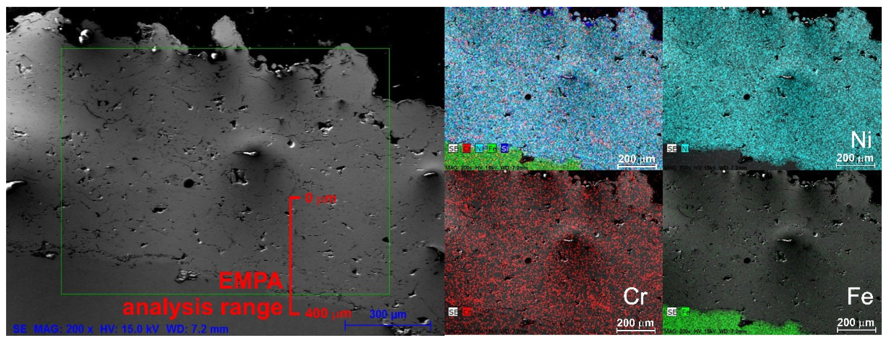
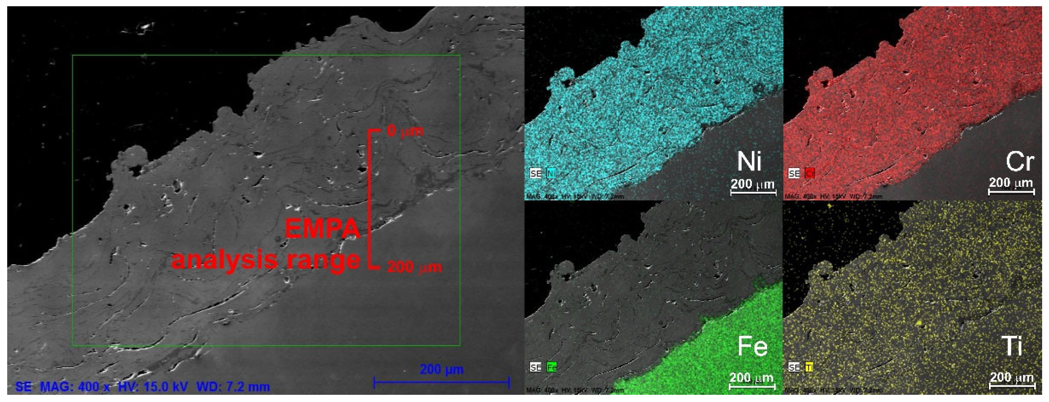
3.3. SEM/EDS and EMPA Results
Figure 8,
Figure 9,
Figure 10 and
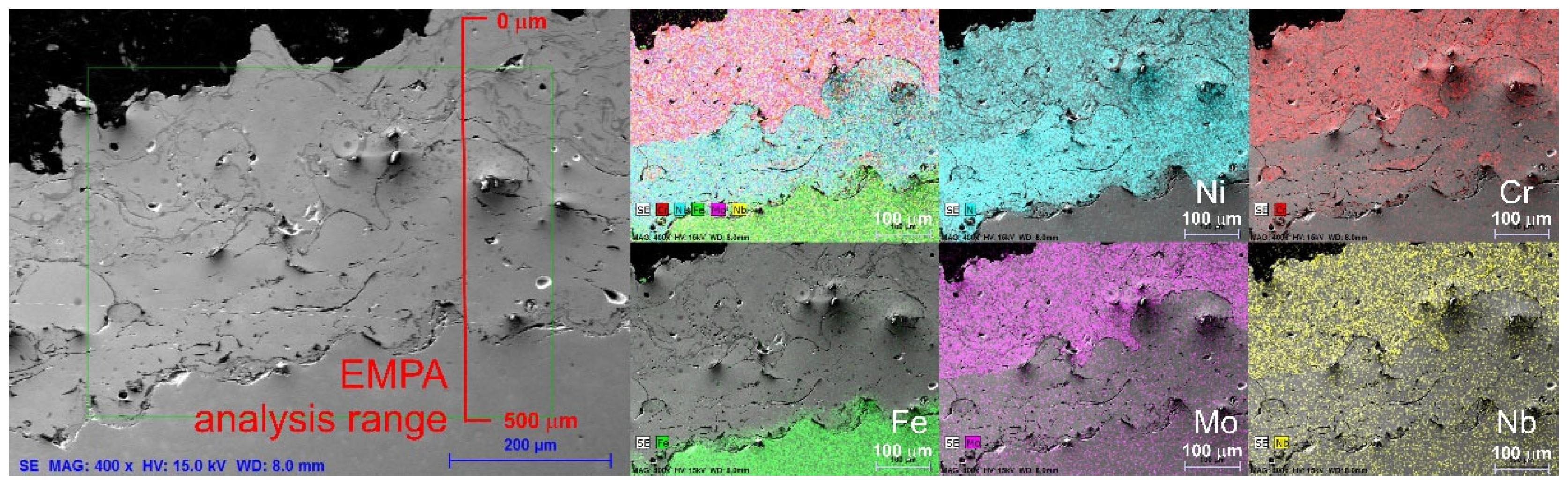
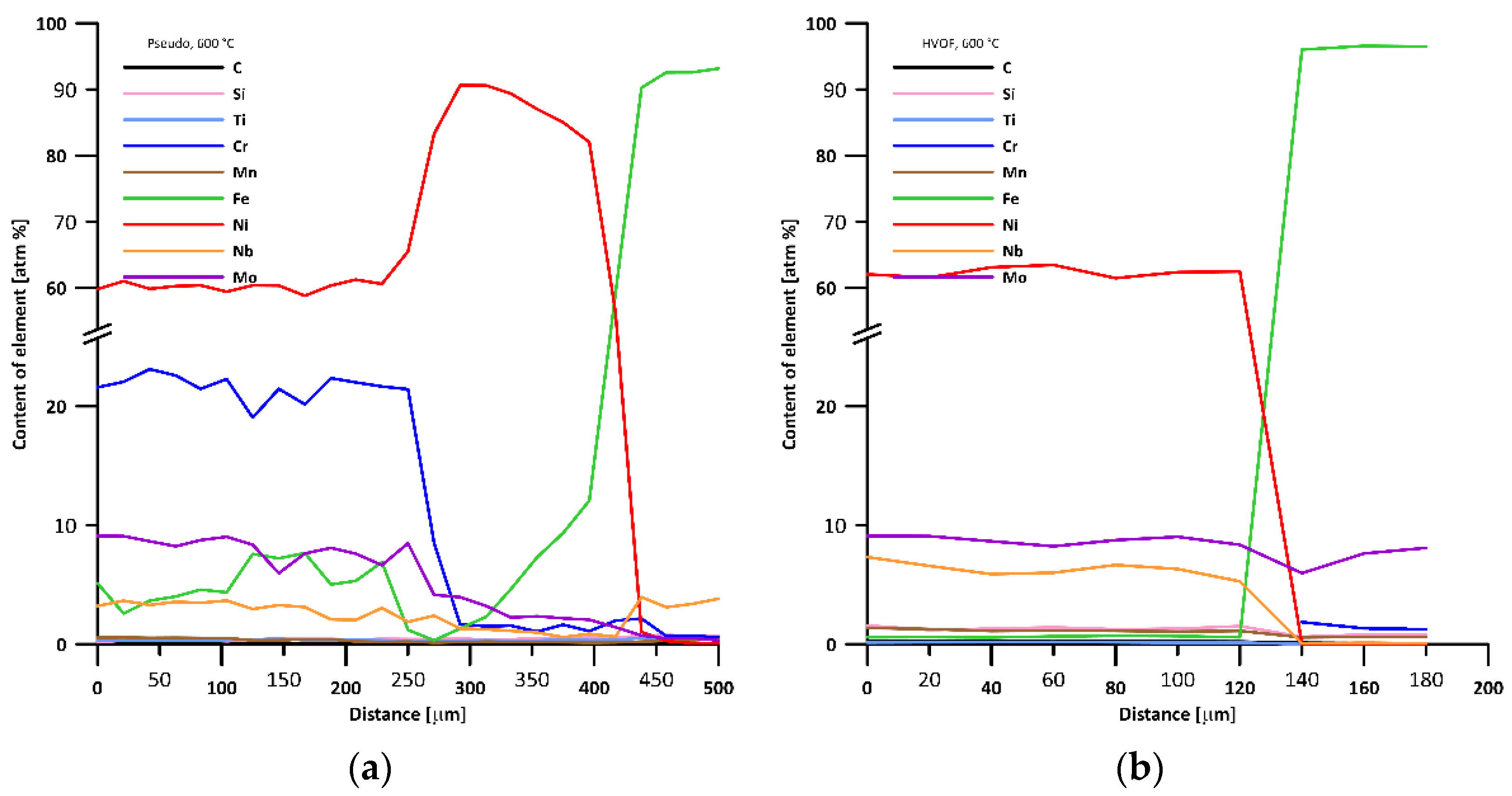
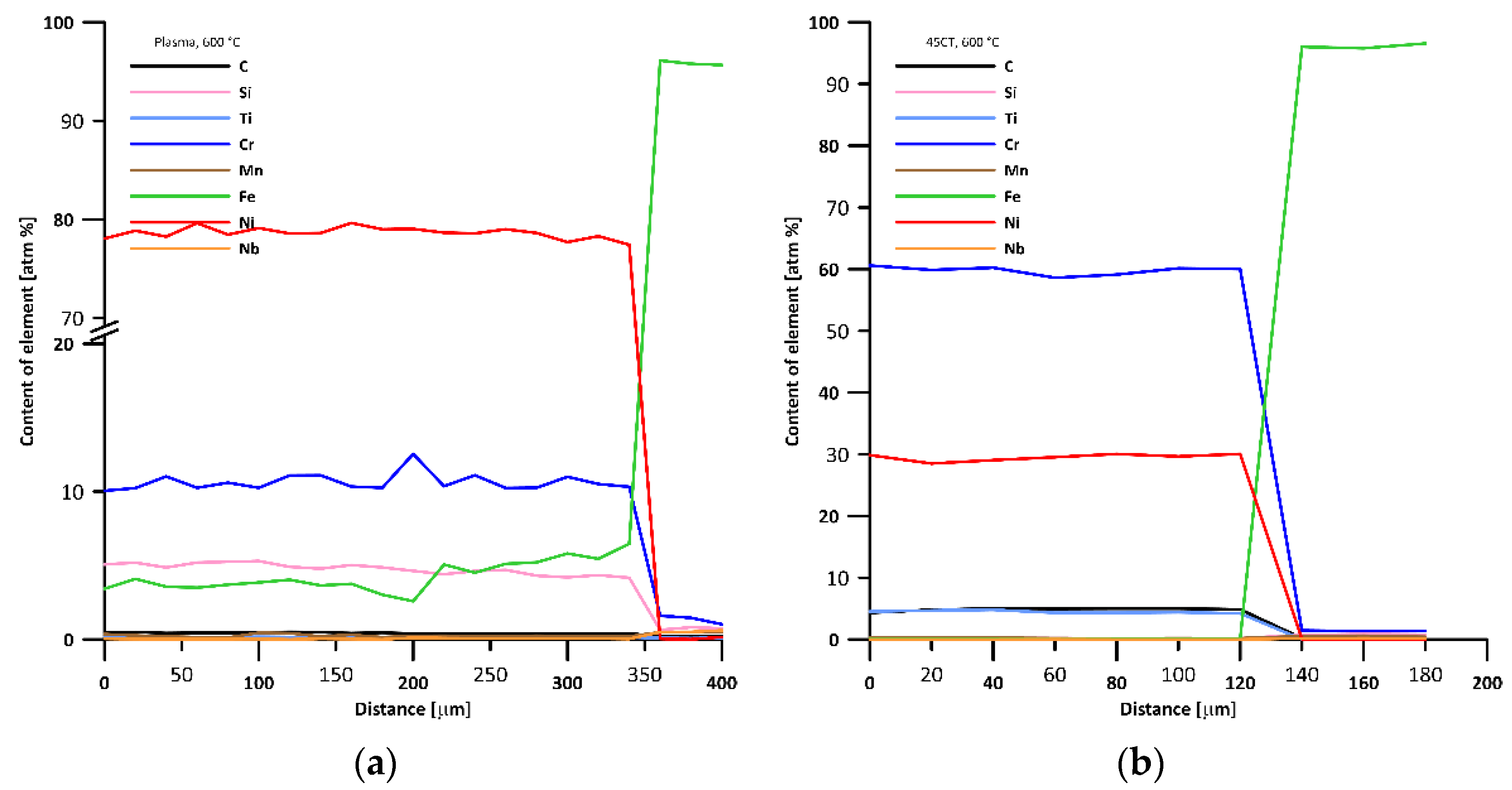
Figure 11 show the SEM/EDS analysis of the coating samples after laboratory exposure for 5000 h at 600 °C in an environment containing sulfur dioxide and hydrogen chloride. In all cases, these coatings were on a 16Mo3 substrate. An electron microscope with an EDS analyzer was used for an overview analysis of the distribution of the individual elements in the coatings, and the elemental maps for each tested coating are shown next to the microstructures (in the case of the TWAS method, only the pseudo-alloy and 45CT alloy coatings are shown). It can be seen from element mapping that the distribution of the individual elements was homogeneous for all coatings except for the Pseudo-alloy coating, which displayed an interlayer of pure nickel on the substrate surface. Even after such a long exposure at 600 °C, no changes in chemical composition were observed in the cross section of the coatings, and no new phases were observed in the structure of the individual samples. The left side of the SEM images shows the area (red line) from which line element microanalysis EMPA (electron microprobe analyzer with a multiple WDS detector) was performed from the injection direction inside the base material in order to detect possible changes in the chemical composition of the coatings due to corrosion or diffusion. The analyzed area/line was composed of individual points with a displacement step of 20 μm—each measured point was the average of a total of 10 measurements. The results of the chemical composition of the individual coatings can be seen in
Figure 12a,b and
Figure 13a,b. From these plots of the chemical composition of the tested coatings, it can be seen that no changes in the chemical composition were detected and the coatings were undamaged and practically the same as in the initial state.
Figure 12a shows the underlying nickel layer in the case of the TWAS pseudo-alloy-coated sample, which was between the substrate and the actual protective layer.
4. Discussion
In this work, various hot metal spraying techniques were tested in the laboratory in an environment simulating biomass combustion containing hydrogen chloride. In total, five different coatings produced by three different technologies—TWAS (twin wire arc spray), HVOF, and water-stabilized plasma—were tested. The laboratory tests were carried out at 500 and 600 °C with an exposure time of 5000 h, after which the mass changes were evaluated, and the samples were subjected to metallographic analysis. All the model coatings were deposited on two different substrates, one of which was 16Mo3 steel (a commonly used material for superheater tubes in power units within the Czech Republic) and the other was austenitic refractory steel AISI 310, which is used for supercritical parameters or for environments with high flue gas aggressiveness [
8]. Coatings based on NiCr, Inconel Alloy 625, CoCrAlY, and NiCrMo were also compared for their corrosion behavior with the underlying base materials in order to verify whether it is possible to use these protective systems to increase the durability and reliability of heat exchangers in boilers that stopped burning lignite and switched to biomass combustion.
From the gravimetric results, it was clear that the tested coatings were quite resistant in the specified environment, and their corrosion behavior was mainly influenced by the surface condition and overall porosity in the hot spray. From this perspective, it is clear that the best results were obtained for the specimens produced by HVOF technology, using an alloy that is more likely to be used for aerospace applications and that would clearly be an unnecessarily expensive option for the protection of heat exchangers in power boilers. This was done as a test of the technology itself—the CoCrAlY-based coating produced by HVOF technology showed in all cases better corrosion behavior during the tests than the steels used as base material and tested separately to find a suitable alternative to austenitic steels for superheater construction (for biomass boilers). This type of coating showed almost no porosity and, after exposure for 500 h in an environment containing hydrogen chloride, there was no noticeable corrosion/oxidation layer on the surface; the sample was bluish due to the formation of a thin layer containing cobalt oxides. This type of coating showed perfect cohesion with both austenitic and ferritic–perlite substrate materials, and no delamination was observed during the tests. Due to the almost zero porosity and relatively smooth surface of the HVOF-prepared coatings, the dependence of the mass gains on time was almost linear but at the level of measurement error in absolute values.
The NiCr- and NiCrMo-based thermally sprayed coatings, which were fabricated by TWAS technology, exhibited gravimetric gains virtually identical to those of the base material AISI 310 after exposure in a biomass flue gas model environment. Overall, these values were in the low or low tens of g/m2 and, especially at 600 °C, the weight gains were orders of magnitude lower than for 16Mo3 steel, which was subject to massive oxidation. Since these coatings are layered, there is a certain number of pores or oxidic particles in the microstructure, so that oxidation is more rapid at the beginning of the high-temperature exposure but stops after a while, and the layer corrodes only very slowly; all these samples showed a parabolic character of mass changes. It was observed that after the first 500 h of testing, there was a massive slowing down of oxidation. The cohesiveness of these types of coatings was excellent, and no delamination was observed on either the austenitic or the ferritic–perlite substrate.
The coating prepared by water-stabilized plasma technology based on NiCrSiB showed the highest mass gains during the first 500 h of exposure at both test temperatures. This was probably due to the higher overall thickness of the coating and also to the fact that, when using this technology, increased oxidation of the alloy particles already occurs during the actual protective coating process. However, with longer exposure times, there was a dramatic decrease in the corrosion/oxidation rate, and after an initial high increase in mass, further increases stopped; this was the most significant corrosion-resistant sample of all the tested samples.
5. Conclusions
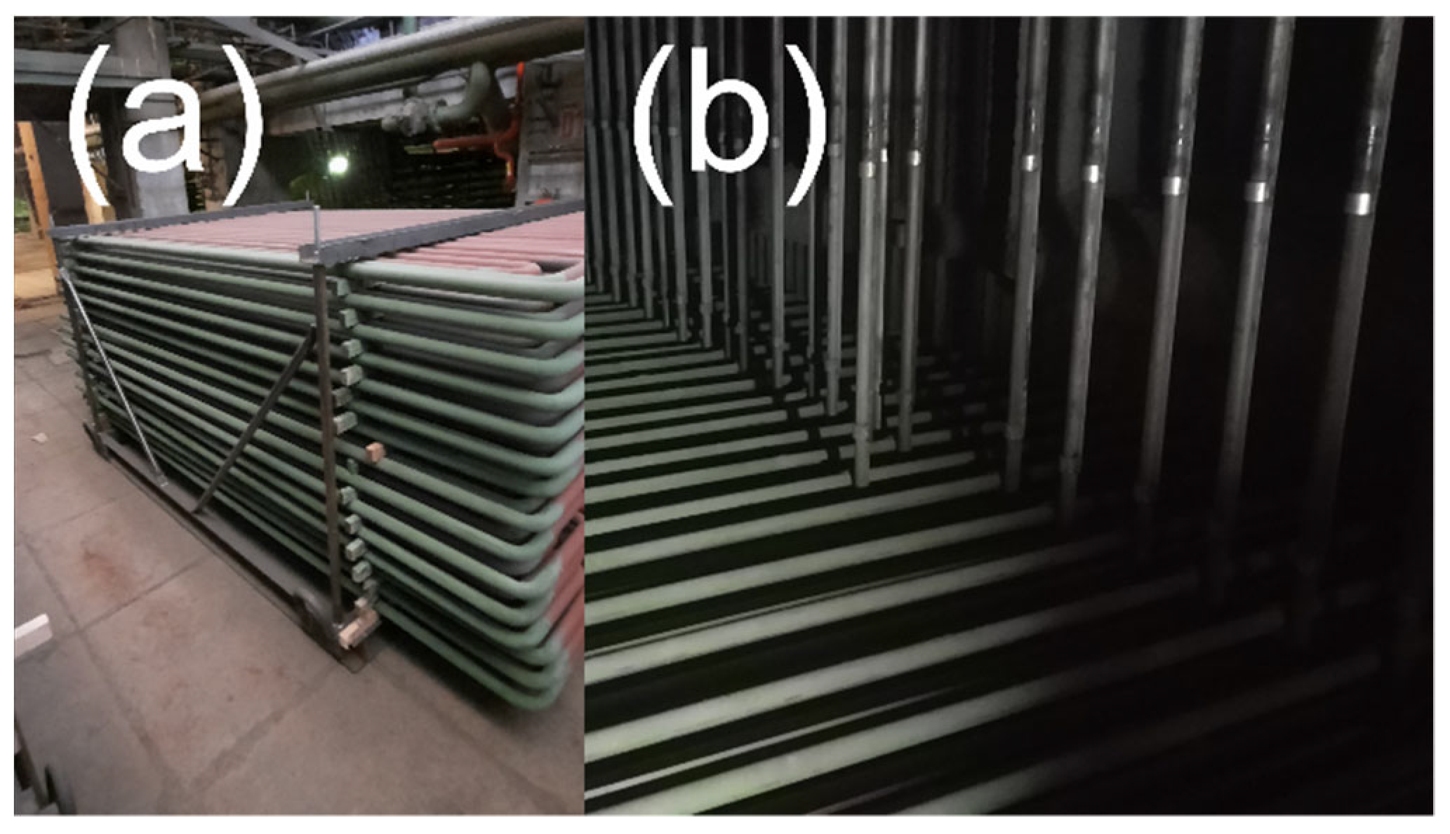
After 5000 h of exposure at 500 and 600 °C in a model atmosphere containing hydrogen chloride, all the tested thermally sprayed specimens were virtually free of signs of corrosion—no significant oxide layers were observed on the outer surface of the specimens or on the sections. Most of the coating types tested exhibited similar or better behavior than the highly alloyed austenitic steel AISI 310, and all the samples tested were significantly more corrosion-resistant than the ferritic–pearlitic steel 16Mo3 commonly used for the heat transfer surfaces of coal-fired boilers. The objective of this work was to laboratory test the protection capabilities of the superheater tubes of a particular power plant boiler that was converted from coal to 100% biomass combustion. On the basis of the results and the complexity of the different technologies, a TWAS (at this stage, the simplest in terms of applicability to the superheater of a real boiler) NiCrMo-based pseudo-alloy coating was selected, which was further coated with ceramic sealing and applied to the outlet superheater of a fluidized bed boiler burning wood chips (see
Figure 14)—during laboratory tests it was shown that there was some difference between the corrosion behavior of the different coatings or of coatings prepared with different technologies, but it was also found that after an initial phase of accelerated oxidation, most of the tested materials underwent a rapid slowdown of oxidation. The results and corrosion behavior of this coating after real exposure will be evaluated in the future months/years and will be the subject of further investigations and studies.
Author Contributions
Methodology, J.C.; Project administration, J.H.; Supervision, J.C.; Validation, J.M.; Writing—original draft, J.H. All authors have read and agreed to the published version of the manuscript.
Funding
This work was performed as a part of the project TK01030089 “Resistance and degradation of alloys in high temperature gaseous medium”co-funded by the Technological Agency of the Czech Republic.
Institutional Review Board Statement
Not applicable.
Informed Consent Statement
Not applicable.
Data Availability Statement
Data sharing is not applicable to this article.
Acknowledgments
The authors would like to thank David Braha (CASTOLIN EUTECTIC, Castolin s.r.o.) for his help with preparation of samples. The authors would also like to thank Adam Poloch for making the metallographically analysis and Jiri Kadlec for analyzing the samples using EMPA.
Conflicts of Interest
All authors declare no conflict of interest. The co-founding agency (TACR) had no role and/or influence on the study and/or on the results of this paper.
References
- 2020 Climate & Energy Package. Available online: https://ec.europa.eu/clima/policies/strategies/2020_en (accessed on 21 August 2020).
- Brief on Biomass for Energy in the European Union. ec.europa.eu. Available online: https://publications.jrc.ec.europa.eu/repository/bitstream/JRC109354/biomass_4_energy_brief_online_1.pdf (accessed on 31 August 2020).
- Recent and Abrupt Increase in Forest Harvesting in Europe. ec.europa.eu. Available online: https://knowledge4policy.ec.europa.eu/publication/recent-abrupt-increase-forest-harvesting-europe_en (accessed on 31 August 2020).
- Michelsen, H.P.; Frandsen, F.; Dam-Johansen, K.; Larsen, H.L. Deposition and high temperature corrosion in a 10 MW straw fired boiler. Fuel Process. Technol. 1998, 54, 95–108. [Google Scholar] [CrossRef]
- Oksa, M.; Auerkari, P.; Salonen, J.; Varis, T. Nickel-based HVOF coatings promoting high temperature corrosion resistance of biomass-fired power plant boilers. Fuel Process. Technol. 2014, 125, 236–245. [Google Scholar] [CrossRef]
- Hardy, T.; Musialik-Piotrowska, A.; Mościcki, K. Negative effects of biomass combustion and co-combustion in boilers. Environ. Prot. Eng. 2012, 38, 25–33. [Google Scholar]
- Krumm, L.; Galetz, M.C. Corrosion of 15Mo3 carbon steel superheater tubes in waste incineration plants: A comparison between a field-returned tube and laboratory tests. Mater. Corros. 2020, 71, 166–177. [Google Scholar] [CrossRef] [Green Version]
- Onaivi, D.; Jibatswen TMichael, O. Effect of Chlorine and Sulphur on Stainless Steel (AISI 310) Due To High Temperature Corrosion. Am. J. Eng. Res. 2016, 5, 266–270. [Google Scholar]
- Babiak, Z.; Wenz, T.; Engl, L. Fundamentals of Thermal Spraying, Flame and Arc Spraying. In Modern Surface Technology; John Wiley & Sons, Inc.: Hoboken, NJ, USA, 2006. [Google Scholar]
- Hrabovsky, M. Thermal Plasma Generators with Water Stabilized Arc. Open Plasma Phys. J. 2009, 2, 99–104. [Google Scholar] [CrossRef]
- Nielsen, H.P.; Frandsen, F.J.; Dam-Johansen, K. Lab-Scale Investigations of High-Temperature Corrosion Phenomena in Straw-Fired Boilers. Energy Fuels 1999, 13, 1114–1121. [Google Scholar] [CrossRef]
- Kalivodova, J.; Baxter, D.; Schütze, M.; Rohr, V. Gaseous corrosion of alloys and novel coatings in simulated environments for coal, waste and biomass boilers. Mater. Corros. 2005, 56, 882–889. [Google Scholar] [CrossRef]
- Ghadami, F.; Sabour Rouh Aghdam, A.; Ghadami, S. A comprehensive study on the microstructure evolution and oxidation resistance of conventional and nanocrystalline MCrAlY coatings. Sci. Rep. 2021, 11, 875. [Google Scholar] [CrossRef] [PubMed]
- Guo, W.; Wu, Y.; Zhang, J.; Hong, S.; Chen, L.; Qin, Y. A Comparative Study of Cyclic Oxidation and Sulfates-Induced Hot Corrosion Behavior of Arc-Sprayed Ni-Cr-Ti Coatings at Moderate Temperatures. J. Therm. Spray Technol. 2015, 24, 789–797. [Google Scholar] [CrossRef]
Figure 1.
(a) Electric arc spraying scheme; (b) schematics of the plasma torch with Gerdien arc.
Figure 1.
(a) Electric arc spraying scheme; (b) schematics of the plasma torch with Gerdien arc.
Figure 2.
Optical light micrographs of the thermally sprayed coatings before testing: (a) HVOF Amperit 469, (b) TWAS 45CT, (c) Plasma K50, (d) TWAS Alloy 625, and (e) TWAS pseudo-alloy.
Figure 2.
Optical light micrographs of the thermally sprayed coatings before testing: (a) HVOF Amperit 469, (b) TWAS 45CT, (c) Plasma K50, (d) TWAS Alloy 625, and (e) TWAS pseudo-alloy.
Figure 3.
(a) Scheme/picture of testing a rod before cutting it into individual samples, with and without coating; (b) testing facility scheme.
Figure 3.
(a) Scheme/picture of testing a rod before cutting it into individual samples, with and without coating; (b) testing facility scheme.
Figure 4.
Comparison between the weight gains (determined after the first 500 h of exposure) of AISI 310 and those of samples of various sprayed coatings after exposure at 500 °C.
Figure 4.
Comparison between the weight gains (determined after the first 500 h of exposure) of AISI 310 and those of samples of various sprayed coatings after exposure at 500 °C.
Figure 5.
Comparison between the weight gains (determined after the first 500 h of exposure) of AISI 310 and of the samples of various sprayed coatings after exposure at 600 °C.
Figure 5.
Comparison between the weight gains (determined after the first 500 h of exposure) of AISI 310 and of the samples of various sprayed coatings after exposure at 600 °C.
Figure 6.
Optical light micrographs of the thermally sprayed coatings after 5000 h at 500 °C in model atmosphere: (a) HVOF Amperit 469, (b) TWAS 45CT, (c) TWAS Alloy 625, (d) TWAS pseudo-alloy, and (e) Plasma K50—16Mo3 steel base material.
Figure 6.
Optical light micrographs of the thermally sprayed coatings after 5000 h at 500 °C in model atmosphere: (a) HVOF Amperit 469, (b) TWAS 45CT, (c) TWAS Alloy 625, (d) TWAS pseudo-alloy, and (e) Plasma K50—16Mo3 steel base material.
Figure 7.
Optical light micrographs of the thermally sprayed coatings after 5000 h at 600 °C in model atmosphere: (a) HVOF Amperit 469, (b) TWAS 45CT, (c) TWAS Alloy 625, (d) TWAS pseudo-alloy, and (e) Plasma K50—16Mo3 steel base material.
Figure 7.
Optical light micrographs of the thermally sprayed coatings after 5000 h at 600 °C in model atmosphere: (a) HVOF Amperit 469, (b) TWAS 45CT, (c) TWAS Alloy 625, (d) TWAS pseudo-alloy, and (e) Plasma K50—16Mo3 steel base material.
Figure 8.
SEM/EDX image of the TWAS pseudo-alloy coating after 5000 h at 600 °C.
Figure 8.
SEM/EDX image of the TWAS pseudo-alloy coating after 5000 h at 600 °C.
Figure 9.
SEM/EDX image of the HVOF coating after 5000 h at 600 °C.
Figure 9.
SEM/EDX image of the HVOF coating after 5000 h at 600 °C.
Figure 10.
SEM/EDX image of the Plasma coating after 5000 h at 600 °C.
Figure 10.
SEM/EDX image of the Plasma coating after 5000 h at 600 °C.
Figure 11.
SEM/EDX image of the TWAS—45CT coating after 5000 h at 600 °C.
Figure 11.
SEM/EDX image of the TWAS—45CT coating after 5000 h at 600 °C.
Figure 12.
Chemical analysis of the coatings performed by EMPA with 20 μm steps (each point is the average of 10 separate measurements). (a) TWAS—pseudo-alloy; (b) HVOF.
Figure 12.
Chemical analysis of the coatings performed by EMPA with 20 μm steps (each point is the average of 10 separate measurements). (a) TWAS—pseudo-alloy; (b) HVOF.
Figure 13.
(a) Chemical analysis of the coatings performed by EMPA with 20 μm steps (each point is the average of 10 separate measurements). (a) Plasma; (b) TWAS—45CT4.
Figure 13.
(a) Chemical analysis of the coatings performed by EMPA with 20 μm steps (each point is the average of 10 separate measurements). (a) Plasma; (b) TWAS—45CT4.
Figure 14.
TWAS coating (NiCrMo-based) on a real superheater in a biomass fluid boiler: (a) before installation, (b) after installation in a boiler.
Figure 14.
TWAS coating (NiCrMo-based) on a real superheater in a biomass fluid boiler: (a) before installation, (b) after installation in a boiler.
Table 1.
Chemical composition of the coating precursors and base materials (wt.%).
Table 1.
Chemical composition of the coating precursors and base materials (wt.%).
| Material | Ni | Cr | Fe | Mo | Si | Co | Y | Nb |
| 16Mo3 | <0.3 | <0.03 | bal. | 0.25–0.35 | <0.35 | – | – | – |
| AISI 310 | 19–22 | 24–26 | bal. | – | <1.5 | – | – | – |
| K50-Plasma | bal. | 9.5 | 3.5 | – | 4.00 | – | – | – |
| TWAS 45CT | bal. | 42–46 | <0.5 | – | <0.2 | – | – | – |
| HVOF Amperit 469 | – | 23–27 | – | – | 0.6–0.9 | bal. | 0.6–0.9 | – |
| TWAS Alloy 625 | bal. | 20–23 | <5 | 8–10 | <0.5 | <0.5 | – | 3.15–4.15 |
| TWAS Pseudo-alloy 1 | bal. | 20–23 | <5 | 8–10 | <0.5 | <0.5 | – | 3.15–4.15 |
| TWAS Pseudo-alloy 2 | bal. | 25–28 | – | 15–18 | – | – | – | 5.0 |
| Material | Mn | Al | Cu | Ti | C | Ta | N | B |
| 16Mo3 | 0.40–0.90 | – | <0.3 | – | 0.12–0.20 | – | <0.012 | – |
| AISI 310 | <2 | – | – | – | <0.1 | – | <0.11 | – |
| K50-Plasma | – | – | 0.3 | | <0.3 | – | – | 2.5 |
| TWAS 45CT | <0.2 | – | <0.5 | 0.3-1 | 0.01–0.1 | – | – | – |
| HVOF Amperit 469 | – | 6.5–8.5 | – | – | 0.6–0.9 | 6.9–9.5 | – | – |
| TWAS Alloy 625 | <0.5 | <0.4 | – | <0.4 | <0.1 | – | – | – |
| TWAS Pseudo-alloy 1 | <0.5 | <0.4 | – | <0.4 | <0.1 | – | – | – |
| TWAS Pseudo-alloy 2 | – | – | – | – | – | – | – | 3 |
Table 2.
Testing atmosphere composition.
Table 2.
Testing atmosphere composition.
| Compound | HCl | SO2 | CO2 | CO | O2 | N2 |
|---|
| Content | 200 ppm | 30 ppm | 12 vol% | 50 ppm | 3 vol% | bal. |
Table 3.
Gravimetric results of coatings/materials after exposure at 500 °C in model atmosphere—in g/m2.
Table 4.
Gravimetric results of coatings and materials after exposure at 600 °C in model atmosphere, in g/m2.
| Publisher’s Note: MDPI stays neutral with regard to jurisdictional claims in published maps and institutional affiliations. |
© 2022 by the authors. Licensee MDPI, Basel, Switzerland. This article is an open access article distributed under the terms and conditions of the Creative Commons Attribution (CC BY) license (https://creativecommons.org/licenses/by/4.0/).


