Review

Nondestructive Testing Technologies for Rail Inspection: A Review

by
Wendong Gong
1,
Muhammad Firdaus Akbar
1,*,
Ghassan Nihad Jawad
2,
Mohamed Fauzi Packeer Mohamed
1 and
Mohd Nadhir Ab Wahab
3,*
1
School of Electrical and Electronic Engineering, Universiti Sains Malaysia, Nibong Tebal 14300, Malaysia
2
Department of Electronics and Communications Engineering, University of Baghdad, Baghdad 10071, Iraq
3
School of Computer Sciences, Universiti Sains Malaysia, Gelugor 11800, Malaysia
*
Authors to whom correspondence should be addressed.
Coatings 2022, 12(11), 1790; https://doi.org/10.3390/coatings12111790
Submission received: 15 October 2022 / Revised: 17 November 2022 / Accepted: 17 November 2022 / Published: 21 November 2022

Abstract

:
Alongside the development of high-speed rail, rail flaw detection is of great importance to ensure railway safety, especially for improving the speed and load of the train. Several conventional inspection methods such as visual, acoustic, and electromagnetic inspection have been introduced in the past. However, these methods have several challenges in terms of detection speed and accuracy. Combined inspection methods have emerged as a promising approach to overcome these limitations. Nondestructive testing (NDT) techniques in conjunction with artificial intelligence approaches have tremendous potential and viability because it is highly possible to improve the detection accuracy which has been proven in various conventional nondestructive testing techniques. With the development of information technology, communication technology, and sensor technology, rail health monitoring systems have been evolving, and have become equally significant and challenging because they can achieve real-time detection and give a risk warning forecast. This paper provides an in-depth review of traditional nondestructive techniques for rail inspection as well as the development of using machine learning approaches, combined nondestructive techniques, and rail health monitoring systems.

1. Introduction

In recent years, the train density, running speed, and load capacity of railway transportation have increased rapidly, especially in high-speed rail transportation [1,2]. Railway transportation has become more and more important in the modern transportation system. Thus, rail safety is becoming more of a concern [3]. Rails bear high mechanical loads and harsh environmental conditions routinely. On the one hand, the mechanical loads are mainly from the weight of the wheels. Therefore, the rolling contact pressure and the sheer and bending forces affect the rails [4]. On the other hand, rails are usually exposed directly to the natural environment, so corrosion, thermal stress, and other phenomena are generated. Significantly, thermal expansion greatly influences seamless rails used in high-speed railways, affecting the rail’s internal stress concentration [5,6].
The rail defects mainly distribute on the different parts of the rail, such as the rail head, rail web, rail foot, and other particular parts. The stress is concentrated on the rail head [7]. Hence, the typical rolling contact fatigue defects are mainly distributed on the surface and inside of the rail head, such as wear, stripping, cracks, crushing, corrosion, and internal damage. The significant defects of the rail web are cracks, bolt-hole fatigue, and excessive web corrosion [8]. For the rail foot, cracks and corrosion are the major defects. In addition, the defect type is even more complex on other parts of the rail, such as the welding and turnout [9].
Cracks are the most challenging to detect among the different types of defects because they are usually small and shallow [10]. The micro-cracks and sub-surface oblique cracks, which occur at the early stage, are highly concealable [11]. However, from the view of fracture mechanics, rail defects are usually generated by rail fatigue cracks, expansion to internal injury, and eventually fracture, especially in welding parts [12]. Thus, the early detection of rail defects is of great significance. A major train derailment occurred at the Hatfield site in the UK in October 2000. The accident was caused by rolling contact fatigue cracks in the rail, which mainly occurred on the top surface of the rail and were continuous, and extended deep inside the rail, causing a sudden break in the rail when the train passed [9].
There are numerous requirements and challenges for detecting rail defects in the early stage. The most salient of them can be summarized as follows:
(1)
The inspection of rail defects should feature high sensitivity since it is required to detect sub-surface oblique cracks and internal damages [13].
(2)
The inspection should cover the entire cross-section of the rail, from the contact surface, through the internal waist, to the rail bottom. Moreover, particular areas such as switch tips and welded joints represent a challenge due to their complex structures and inherent changes in material properties.
(3)
In addition to the speed and efficiency requirements, inspecting rails should be non-contact. This way, the inspection can be carried out quickly and efficiently using movable inspection wagons that can reach the speed of a train (around 120 km/h).
(4)
Due to the complexity of the mechanisms that cause rail damage, it is significantly challenging to achieve a reliable quantitative and qualitative assessment of rail defects.
Traditionally, the primary method of rail defect detection has been human manual inspection. However, this method is cumbersome, hard work, and prone to human error. In addition, the personal safety of the inspectors is also an issue that needs to be ensured [14]. Therefore, this type of inspection has been replaced over time with automated, more efficient inspection methods.
Nondestructive Testing (NDT) can be defined as an evaluation technique based on the integrity of the object to be evaluated. In other words, it provides insurance for the integrity and properties of the object itself. Ideally, NDT techniques obtain information about all the aspects of the object’s defects and, by doing so, evaluate it according to the relevant technical standard [15].
In 1959, the first ultrasonic rail inspection vehicle was put into use [16]. Since then, NDT technologies to inspect rail defects have been inherent to various aspects of railway systems, such as production, installation, and maintenance. Different NDT techniques have been applied in rail inspection and evaluation, with advantages and limitations. This paper aims to review the application of these techniques in rail inspection and compare them based on their features and rules. In addition, this paper discusses the current research status in this field by reviewing modern rail health intelligent monitoring systems and the new trends in applying artificial intelligence to rail defect NDT technologies.
The rest of this paper is organized as follows: First, a comprehensive review is given of the most prominent NDT techniques, such as visual detection, ultrasonic detection, eddy current detection, magnetic flux leakage detection, alternating current field measurement, barkhausen noise testing, and acoustic emission technology. When used for rail flaw inspection, their advantages and shortcomings will be given. Second, the rail health intelligent monitoring system will be introduced because it is a development trend in the future. Finally, artificial intelligence and combined NDT techniques will be introduced because they can improve detection accuracy and overcome some limitations.

2. NDT Method

NDT methods used for rail defects detection can be categorized into two main types: machine visual inspection and physical inspection. The former is based on applying different image processing methods to segment and identify images of the rail to obtain enough information about the defect. On the other hand, the latter relies on a range of physical signal processing schemes to inspect the rail. This section will discuss each category by illustrating its types and main features.

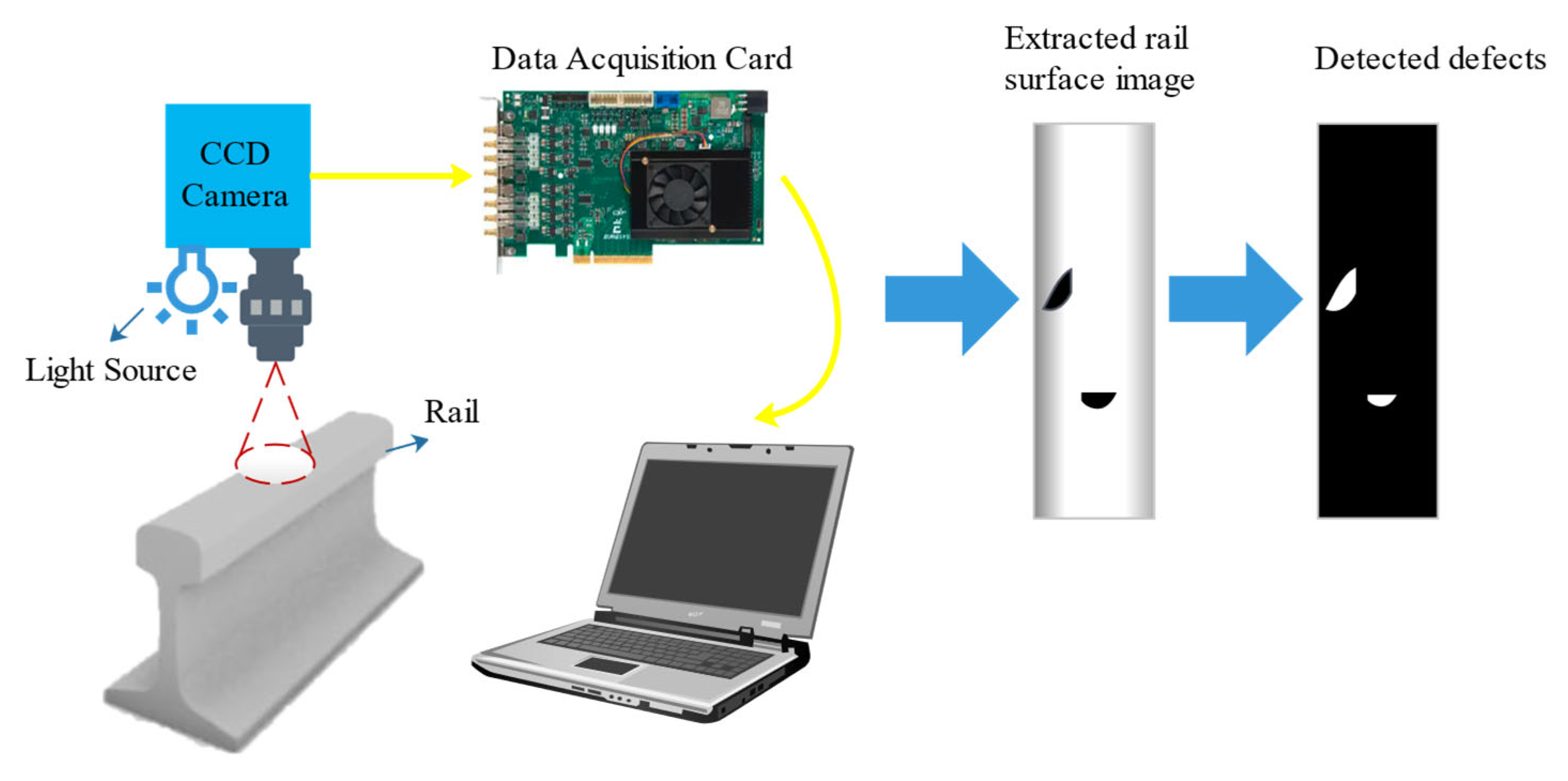
2.1. Visual Inspection Methods

The visual inspection method is a non-contact inspection method that is widely used in nondestructive testing because of its speed and accuracy [17]. For rail flaw detection, visual inspection is based on the use of a high-speed camera, which can capture images of the rail (especially the rail surface) as the train moves over the rail. Then the image data will be transported to the computer via a data acquisition card. Finally, the software will process the captured image data to determine whether there are defects on the rail. The visual inspection method is suitable for detecting defects such as cracks, deformation, and corrosion on the rail surface. The principle of visual inspection is shown in Figure 1.
It can be seen from Figure 1 that the extracted rail surface image can be obtained from the visual system first. Then the image is converted to grayscale so defects can be detected at high contrast. Automated visual inspection systems can be used to measure the rail head profile and percentage of wear, rail gap, moving sleepers, absence of ballast, base plate condition in the absence of ballast, pincers position, missing bolts, and surface damage [18]. Depending on the inspection type and the required resolution quality, the speed can vary from 1 to 320 km/h [19].
Several factors can affect the accuracy during visual NDT of rails. First, the resolution of the captured video image needs to be higher to provide reliable data for analysis because of the blurring effects during the movement of the camera [20]. Second, the conventional camera cannot obtain the image data about the depth. Third, the environment light changes during the whole day, and the changes in the surrounding light environment significantly impact the capturing image data and influence the stability of defect detection. Numerous studies have been conducted to address the above issues.
For the first issue, color line scan cameras and spectral image differencing methods are currently effective in detecting rail surface defects. A charge coupled device (CCD) camera with a powerful scanning function and good image clarity, which supports multiple merged pixel modes, has been used to inspect rail visually [21]. It has high sensitivity and a high signal-to-noise ratio of captured images. Furthermore, linear CCD, a kind of image sensor, can acquire images via an A/D converter, timing generator, data storage, and other control logic [22]. Finally, the image data is converted to be digital signal and processed for rail surface defect detection. The non-contact and dynamic rail flaw inspection platform with fast line matrix CCD camera technology has been verified at 120 km/h [23]. When the inspection speed is high, the time for the analysis process should be short for achieving real-time detection. However, as the resolution of the image increases, so does the amount of data acquired, and hence more computational time is needed to complete the analysis. As a result, inspection speed needs to be adjusted to keep pace with data analysis. If a real-time evaluation is impossible, then data analysis can be conducted offline to identify any defective areas of the track section [24]. The Rail Check rail inspection vehicle, developed by Alias Elektronik in Germany, can automatically detect rail surface defects by capturing a two-dimensional image of the rail with cameras [25]. The VIS integrated rail inspection system developed by ENSCO company was equipped with four-line laser CCD cameras to capture the image information of the rails [26]. It has been verified that it could automatically detect cracks on the rail surface.
For the second issue, three-dimensional (3D) vision technologies, including binocular stereo vision and 3D structured light technology, have been progressively used in the visual inspection of rails [27]. Binocular Stereo Vision is an essential machine vision based on the parallax principle. It uses an imaging device to acquire two images of the object to be measured from different positions and to obtain three-dimensional geometric information about the object by calculating the position deviation between the corresponding points of the images. The 3D structured light camera projects a specific structured light illumination pattern onto the target object, then the image modulated by the target will be captured by the camera. The 3D information of the target object will be derived through image processing and visual modeling, and the 3D coordinates of each point in the space within the field of view can be collected [28]. Finally, the 3D stereo imaging is intelligently acquired through algorithmic recovery.
For the third issue, combining machine vision and 3D linear laser inspection technology for rail surface defect detection can partly overcome the effects of light change since the camera can scan the rail surface under linear laser illumination [29]. Meanwhile, the accuracy of visual inspection for rail defects can be further improved in the light-changing environment by algorithmic processing of the image data. The process of detecting rail defects uses image processing techniques, including pre-processing, feature extraction, defect classification, defect quantification, and other steps. The pre-processing steps of the visual inspection typically include greyscale, image enhancement, and image segmentation. Sub-images of the rail can be cut by the rail extraction algorithm first, then the contrast of the rail image can be enhanced using the local normalization (LN) algorithm [30]. By pre-processing the image data, the coarse extractor of the algorithm can be used to locate defects in the rail surface image roughly. Meanwhile, the fine extractor of the algorithm can be used to determine whether the points for which anomalies are obtained are real defects or other noisy points. Therefore, the noisy points can be discarded to obtain the true results of the image data. During the feature extraction process, the defects can be characterized by algorithms such as Histogram of Oriented Gradient, Local Binary Pattern, and Directional Chain Codes [31]. Various kinds of algorithms have been applied for rail flaw inspection to increase the accuracy of the classification. For instance, K-means and decision trees can be used in detecting rail surfaces by machine vision, mainly to classify rail defects [32]. The quantification of the defects can use the learning-from-examples technique, which is related to the image processing speed capability of the system [33]. Deep learning detection methods are a kind of supervised learning scheme, and they can learn from large amounts of image data, then accurately identify new image samples [34]. Deep learning detection methods have better generalization and robustness, and detection results are better than traditional methods [35,36].
As described, visual nondestructive inspection of rails has a high speed and accuracy. Unfortunately, it has limitations in providing any information with regard to the presence of internal defects. Therefore, it cannot be used to substitute ultrasonic inspection.

2.2. Physical Inspection Methods

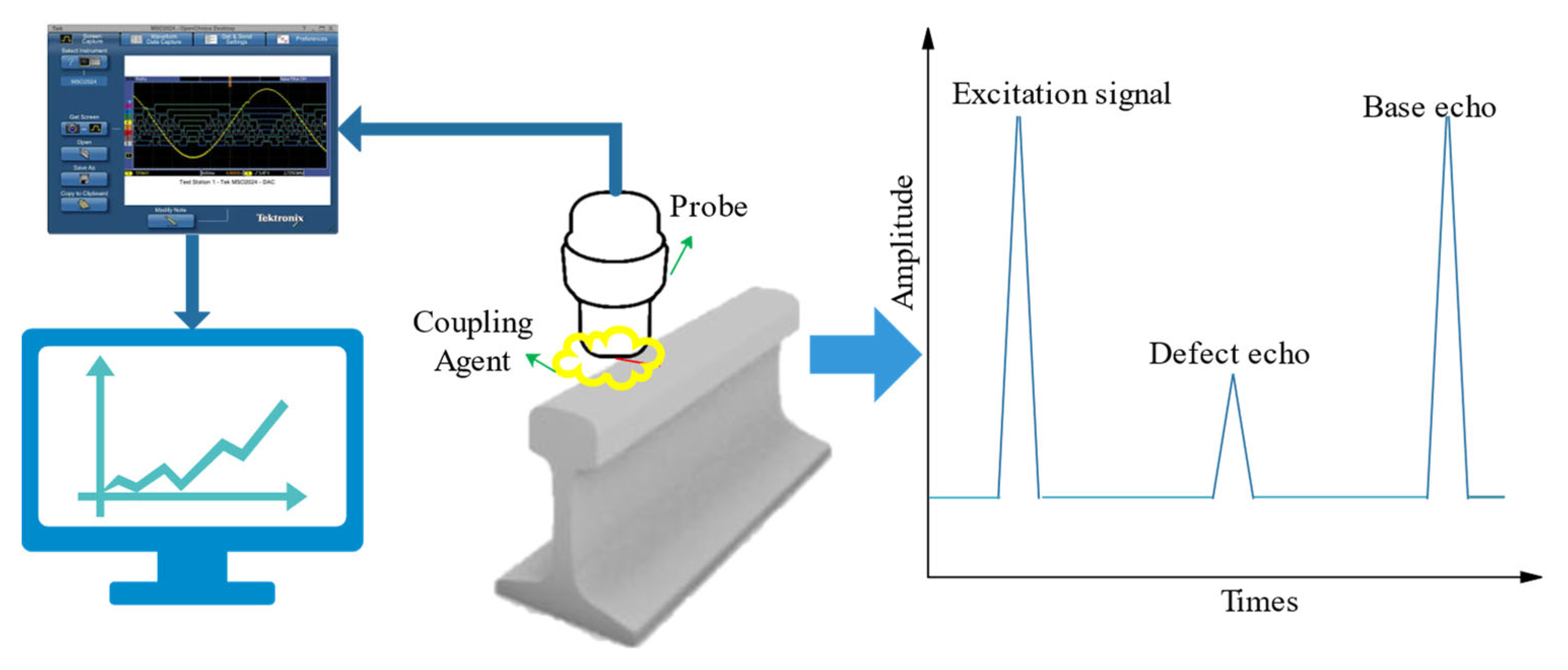
2.2.1. Ultrasonic Inspection

Ultrasonic NDT uses ultrasonic waves’ reflection, diffraction, and transmission characteristics to determine whether there are defects inside the workpiece [37]. When inspecting rails with traditional ultrasonic probes, a piezoelectric device transmits an ultrasonic energy beam into the rail. Then a group of transducers detects the transmitted beam’s reflected or scattered energy. Finally, the position and nature of the identified flaws and the overall structural integrity of the rail under examination can be learned from the amplitude of the reflections and the timing of their occurrence [38]. The principle of ultrasonic inspection is shown in Figure 2.
It can be seen from Figure 2 that not only the base echo but also the defect echo are detected after the excitation signal when there is a defect in the detection area. Therefore, we can detect the defects from the characteristics of the wave. Conventional ultrasound technology has been widely used for internal rail defects detection because it has a high penetration capacity. Based on ultrasonic sensors, a real-time photoacoustic imaging system for nondestructive testing of rails can be established [39,40]. The location, direction, and depth of rail defects can be effectively identified by reconstructing the image from the photoacoustic signal. Therefore, it can scan internal rail defects automatically because of its high detection sensitivity. To reduce rail breakage caused by internal rail damage, Network Rail in the UK has developed the handheld rail flaw detector and the rail inspection train based on UT technology, which can effectively detect internal rail core damage [41]. A University of California research team developed ultrasonic inspection equipment with efficient data processing algorithms to accurately detect rail stripping and corrosion defects. The GTC-80 rail flaw detection vehicle, developed by the Chinese Academy of Railway Sciences, was based on ultrasonic detection technology to achieve online flaw detection of high-speed rail [42]. It can effectively detect rail damage with a detection speed of 80 km/h (approx. 22 m/s).
Ultrasonic rail inspection can be performed manually or on special test vehicles. However, conventional ultrasonic has several limitations. Firstly, conventional ultrasonic NDT has a limited speed and cannot be used in long-distance detection because it requires a coupling agent to fill the gap between the probe and the measured surface. The inspection speeds verified in the experiment were only from 40 up to 80 km/h by conventional ultrasonic NDT. In reality, however, inspection speeds can be as low as 15 km/h, particularly when the vehicle must be manually verified [43]. Secondly, it is difficult to detect rail defects with complex shapes or irregular shapes because of the limits of conventional multi-probe ultrasound inspection systems. Thirdly, the defects on the top surface of the rail and the near-surface fatigue damage cannot be effectively detected and assessed. The fatigue crack on the top surface of the rail prevents the ultrasonic wave from being incident into the measured parts, which will have a negative impact on the detection of internal defects in the structure below the fatigue crack. Especially near the gauge angle of the horizontal direction, the defects which have longitudinal extension will have a reflective effect on the ultrasonic wave, preventing the incidence of the sound beam and resulting in the failure to detect the dangerous defects buried below it [44].
New techniques have been developed, such as ultrasonic phased-array inspection, ultrasonic guided wave inspection technology, electromagnetic ultrasound technology, and laser ultrasound technology, to overcome the limitations of conventional ultrasonic NDT techniques.
The ultrasonic phased-array system consists of multiple arrays of independent piezoelectric wafers. The spotlight’s position and orientation are controlled by specific rules and timing sequences, which can effectively detect internal defects of complex shapes with high accuracy [44,45]. Ultrasonic phased-array systems are gradually replacing conventional multi-probe ultrasound inspection systems. The new automated ultrasound inspection system consists of a pair of phased-array probes, and it is capable of performing a large number of tasks [46,47]. Ultrasonic defect detection systems consisting of phased-array probes and field-programmable gate array (FPGA) modules can increase the speed and accuracy of detection [48]. Especially in particular locations such as welds, ultrasonic phased-array inspection has proved more efficient than conventional ultrasonic inspection.
Guided waves are a kind of long-range ultrasonics that can be effective over distances up to 30 m from the sensor array [49]. At semi-infinite or two semi-elastic media surfaces, ultrasound waves are reflected or transmitted due to differences in the material properties of the media, resulting in a shift in the waveform [49,50,51]. Due to different waveforms and different propagation speeds, different waveforms propagate in the medium at their inherent speeds. When ultrasound waves are propagated in a medium with boundaries, such as steel rails, various reflected, transmitted, refracted, and interfacial waves appear as coupled waveforms, thus forming ultrasound-guided waves [52,53].
Compared with traditional ultrasonic inspection technology, ultrasonic guided wave inspection technology uses low-frequency ultrasonic waves, which have the outstanding advantages of long propagation distance and fast speed. British Rail Network Rail has developed the G-Scan rail ultrasound-guided wave inspection device, which uses low-frequency ultrasound-guided waves to detect defects in aluminum thermal welds over long distances [54,55]. Moreover, the 300 kHz pseudo-Rayleigh guided waves have been used for long-distance detection of different defects on rail undersides [56]. However, various factors can significantly attenuate the signal to the extent that the effective distance may only be a few meters in some cases. The wave mode and frequency selected determine the most effective inspection range.
Meanwhile, the entire object cross-section, including transverse rail defects, can be inspected. For instance, based on the guided wave propagation and scattering characteristics at the bottom of the rail, guided waves can be used to detect oblique cracks at the bottom of the rail in the vertical vibration mode [50]. The pulse-echo method can be used to quickly locate defects at a certain distance from the rail head. Prism, which has been developed by Wavesinsolids LLC in the USA, has a maximum inspection speed of 15 km/h, and it has been reported to be capable of detecting large transverse rail head defects [57]. The static tests were conducted on a piece of rail that contained simulated transverse cracks in the rail head that extended below 20% of the total cross-sectional. The University of Pittsburgh developed the rail head damage detection system based on ultrasonic guided wave technology [58]. It used wavelet transform and unsupervised learning algorithms to identify rail damage and maximize the sensitivity of the detection system. The tests have been carried out on rails at an inspection speed of 10 km/h, with damage detection rates between 75% and 100%. Based on guided wave technology, Gurevich developed an ultrasonic guided wave flaw detector AKR1224 [59]. The equipment used 12 antenna array sensors to detect rail defects. Defects such as rail head stripping, rail head injury, and screw hole crack can be detected from multiple angles. It has a high detection rate. Mariani developed the non-contact ultrasonic guided wave rail inspection vehicle for rapid detection of vertical defects using laser excitation and air coupling.
The electromagnetic ultrasound first generates a high-frequency current in the zigzag coil via an external circuit, which induces eddy currents in the opposite direction on the surface of the rail head. At the same time, the eddy currents caused by the strong static magnetic field provided by the magnet cause vibrations in the surrounding masses, resulting in electromagnetic ultrasound surface waves [60]. Electromagnetic ultrasound technology uses the Lorentz force and magnetostriction effects to excite and receive ultrasound waves in conductive specimens. The orientation of the magnetic field, the geometry of the coil, and the physical and electrical properties of the material under investigation strongly influence the ultrasound generated within the sample [41]. Compared to conventional ultrasonic NDT techniques, it has the advantages of high accuracy, no coupling agent required, non-contact measurement, and fast inspection speed as it is an electromagnetic coupling mechanism that generates the ultrasound within the sample skin depth [61]. Several electromagnetic ultrasound NDT vehicles have been developed. For instance, VIGOR Russia has developed the electromagnetic ultrasound NDT vehicle named UD-EMA-RWT-01M, which can provide complete coverage of the rail head, rail waist, and rail bottom at speeds between 0.1 and 1 m/s [62]. Canadian company Tektrend has developed RailPro, an electromagnetic ultrasonic rail flaw detection system for the online verification of many types of rail defects at speeds between 5–9 km/h [63]. Significantly, the defects include transverse fissures, horizontal and vertical head splits, split webs, bolt hole cracking, and RCF damage.
Laser ultrasonic systems operate by first generating ultrasound in a sample using a pulsed laser. When the laser pulse strikes the sample, ultrasonic waves are generated through a thermoelastic process or by ablation. Pulsed lasers can be used to generate all types of ultrasonic waves, including compressional, shear, surface, and plate waves [64]. When ultrasonic waves reach the sample’s surface, the resulting surface displacement can be measured with a laser ultrasonic receiver based on an adaptive interferometer. Laser pulses can produce sound waves with a wavelength of only a few microns, allowing the detection of minor defects within the material. Therefore, it has high accuracy [65]. No coupling agent is required in the testing process, so acoustic-solid coupling does not affect the testing speed. For complex-shaped workpieces, laser ultrasound technology can generate multiple modes of ultrasonic signals in a single excitation process. Therefore, it can be applied to the real-time detection of micro-cracks in rails with high accuracy in harsh environments. Laser ultrasound detection has been validated by detecting rail internal defects of different sizes [65,66]. Meanwhile, the current automated laser ultrasonic rapid rail defect detection device can detect defects on the rail surface as well as horizontal and vertical rail defects in the rail head at speeds of up to 40 km/h [67,68].
In general, ultrasonic inspection detect deep surface-breaking and internal defects relatively well. However, these high-speed systems usually cannot detect defects smaller than 4 mm deep. Such surface defects can shadow critical internal defects and thus give a false picture of the rail’s structural integrity. Ultrasonic inspection can also miss some defects in the rail foot, especially corrosion, as this part of the rail can only be scanned partially. Meanwhile, they also perform relatively poorly when inspecting alumino-thermic welds.

2.2.2. Eddy Current Inspection

Eddy currents testing (ECT) is commonly used to inspect conductive materials for detecting surface and subsurface defects. Typically, eddy current sensors are comprised of one exciting and one sensing coil. The magnetic field near the surface is generated by feeding an alternating current to the exciting coil. Changes in the magnetic field cause eddy currents to be induced just below the surface. The search coil detects changes in the secondary magnetic field generated by the eddy currents in the form of an induced voltage. When a near-surface or surface defect is present, the eddy currents are disturbed, causing fluctuations in the secondary magnetic field, and giving rise to changes in the impedance [69,70].
ECT can detect near-surface or surface damage on the rail head. Thus, it can complement the performance of ultrasonic transducers. The probe coil can obtain the magnetic field changes, thus obtaining defect characteristics on the rail. The principle of eddy current inspection is shown in Figure 3.
It can be seen from Figure 3 that the eddy current changes when a defect is detected. The dimensional characteristics of defects can be quantified by the characteristic values of eddy current changes. ECT is non-contact and can be used in high-speed inspection. The inspection speed achieved by the combined ultrasonic/eddy current systems is typically 75 km/h, but higher speeds of up to 100 km/h have been reported [71]. Sperry Corporation in the USA combined ECT and ultrasonic inspection techniques to detect rail surface defects and internal defects. Meanwhile, it can detect cracks in different depths by adjusting the eddy current sensor frequency, coil, and other parameters [72,73]. Furthermore, ECT performs well in special areas such as surface defects on the curved-tip rail of the turnout and surface defects on the inside of the variable-section turnout track. Thomas investigated ECT for the detection of contact fatigue cracks and combined it with ultrasound technology for the defects in rail welds and joints [74]. The German Federal Railways has designed and developed two types of rail inspection equipment using eddy current detection technology, which are vehicle-mounted and hand-pushed [75]. The inspection train, which was vehicle-mounted with eight eddy current probes, four for each rail, can be used at a speed of 50 to 80 km/h to achieve routine inspection of rails. Furthermore, the hand-pushed equipment was equipped with four eddy current probes, which can detect railway turnouts and areas that cannot be reached by trains.
However, ECT has a collective skin effect and only detects the surface and near-surface structural state of conductive materials. In addition, the main issue for the eddy current inspection is that this type of sensor is susceptible to lift-off variations. Thus, the distance between the detection probe and the measured rail surface should be kept fixed (generally within the range of 2 mm) [76]. For that reason, the probe needs to be positioned at a constant distance from the surface of the rail. Particular attention must be given to any lift-off variations that may occur during an inspection. The changes in the lift-off variable could influence the accuracy of the predicted depth.
Pulsed Eddy Current (PEC) is proposed to enhance the penetration of eddy currents. PEC uses a pulsed excitation signal to induce transient eddy currents in the part being measured [77]. The coil induces a time-varying voltage, which is analyzed to detect defects at different depths, characterize properties, and assess the condition of the specimen by analyzing the change in frequency of the transient currents. The technology has the advantages of rich spectrum content for detecting and identifying defects at different depths, fast detection speed, and non-contact detection. Newcastle University in the UK was the first to experiment with this application in the area of rail defects with good results [78].
Furthermore, PEC can integrate with thermal imaging technology based on electromagnetism’s eddy current and Joule heat phenomena. Eddy Current Pulsed Thermography (ECPT) uses infrared thermography to obtain the temperature distribution and conduction of conductive specimens under pulsed eddy current excitation [79]. The length, width, depth, and inclination of rail defects can affect the thermographic data. The principle of ECPT is shown in Figure 4.
It can be seen from Figure 4 that the thermal imaging of a defect is clearly distinguishable from the surrounding background. Therefore, the size of the defects can be analyzed by image-recognizing techniques. ECPT combines the advantages of pulsed eddy current and infrared thermography. Thus, it can rapidly visualize the rail fatigue cracks. Furthermore, it can concentrate the heat on the defects. Therefore, the temperature difference between the defective and non-defective areas increases, and spatio-temporal characteristics and rich transient information can be obtained. Thus, it can improve the signal-to-noise ratio and detection sensitivity, especially for small defects such as fatigue multi-crack and micro-defect damage on the rail surface [80]. With that, Vrana J. developed the ECPT systems, which can effectively detect cracks in 0.1 mm resolution in depth. Moreover, the longitudinal parallel crack can be detected using ECPT [81]. The Fraunhofer Institute for Nondestructive Testing in Germany has applied ECPT technology to detect rail and wheel surface cracks. They mounted the equipment on the rail test vehicle. The results showed that at low speeds (2 km/h), the device could effectively image rail surface cracks and at a maximum travel speed of 15 km/h (approx. 4 m/s), the device can only detect large rail surface defects [82].
The main factors affecting the ECPT are the excitation coil, the yoke, the temperature rise, and the type of defect. Therefore, the temperature distribution of rail surface defects was investigated through induction thermography simulation and experimental analysis. The results indicated that the eddy current penetration correlated with the temperature rise. Using single-turn coils to detect small cracks on the rail surface by ECPT will easily cause uneven heating. Thus, the improved Helmholtz coil excitation structure was developed to enable uniform heating of the rail surface, eliminating the shortcomings of single-turn coil non-uniform heating in the detection [83]. Meanwhile, the ferrite yoke excitation structure was used for uniform heating and unobstructed visualization of defects on the top surface, facilitating quantitative assessment of defects.

2.2.3. Magnetic Flux Leakage Inspection

The magnetic flux leakage (MFL) inspection method has been widely used for ferromagnetic materials evaluation. Permanent magnets or DC electromagnets are usually used to generate a strong magnetic field to magnetize the specimen to saturation [84]. The magnetic flux lines are coupled into the specimen using metal brushes or air coupling [85]. When the rail is magnetized, defects on or near the rail surface cause a change in magnetic permeability. Then the direction of magnetic induction lines will be changed, with some of the flux leaking onto the surface. Magnetic sensors can detect the leakage field to analyze the rail surface defects. The principle of MFL inspection is shown in Figure 5.
It can be seen from Figure 5 that when the magnetic lines encounter defects, the magnetic lines are bent. This is because the magnetic field lines are refracted as they pass through the interface between a ferromagnetic object and air. The leakage field from the defect can be analyzed by Finite Element Simulation, and then the flux density distribution curve can be obtained. The simulation results indicated that the features of the leakage signal could be obtained from the leakage flux density curve [86]. Therefore, it can be used to identify the defect information.
In 1928, Dr. Elmer Sperry successfully developed the world’s first rail flaw detection vehicle based on the principle of magnetic leakage detection under the auspices of the American Railway Union [87]. It could detect surface and near-surface cracks in rails very well but could not detect complex components and deeper defects.
There were several limits for rail MFL inspection. Firstly, the defect’s depth is difficult to identify by permanent magnets or DC electromagnets. Secondly, increasing inspection speed also has a negative impact on MFL. The magnetic flux density in the rail decreases with increasing speed. As a result, the signal becomes insufficient to detect at speeds more than 35 km/h [88]. However, research by new technologies has gradually solved these issues in recent years.
For the first limit, the current research integrates pulse leakage and pulse reluctance technology to detect different depths of rail cracks on the rail surface, achieving better results [89]. Furthermore, MFL inspection equipment by sensor array can obtain more information about the leakage field. Therefore, it can significantly improve the prediction accuracy of defects, especially for the depth of the defects. Meanwhile, the sensor array can form the three-dimensional leakage magnetic field image to describe rail defects [90].
For the second limit, in [91], the authors investigated that hall sensors in MFL systems can improve their performance at higher speeds. Meanwhile, in [86], the authors simulated the leakage magnetic field at high speed to study the dynamic magnetization and velocity effect in the high-speed leakage detection of rail cracks. The research above reduced the speed effect during rail flaw inspection by MFL techniques. In [92], the authors reviewed the nondestructive testing method of metal magnetic memory and established a magneto-mechanical model based on a nonlinear constitutive relation for ferromagnetic materials under a constant weak magnetic field. Theoretical results obtained from the proposed model are more consistent with experimental data, and the proposed magneto-mechanical model applies to various ferromagnetic materials. Meanwhile, in [93,94,95,96] the authors investigated a magnetic shielding strategy and assessed the evaluation of defect depth in ferromagnetic materials via the magnetic flux leakage method with a double Hall sensor.
Near-surface or surface defects like cracks on rail heads are particularly well-detected by MFL sensors. However, internal defects cannot be detected because they are too far from the sensor coils. Therefore, MFL is commonly used as a complementary technique to ultrasonic inspection because it cannot detect internal defects.

2.2.4. Other Physical Inspection Methods

Alternating current field measurement (ACFM) is based on the principle that an alternating current can be induced to flow in a thin skin near the surface of any conductor. The geometry of the component cannot affect the alternating current [97]. Measuring changes in the current on the rail surface enables fast and accurate non-contact detection.
When using ACFM probes, a maximum operating lift-off of 5 mm is possible without suffering a significant loss of signal, in contrast to eddy current sensors, which must be positioned at a close (2 mm) and constant distance from the inspected surface [98]. The signal strength of the eddy current sensor decays with the cube of the lift force. However, the signal strength of the induction sensor decays with the square of the lift force. As a result, the ACFM technique can handle a much higher lift-off [99]. The hand-pushed detection vehicle has been designed based on ACFM technology to detect fatigue damage on the rail surface [100]. It was used to test different sizes of defects on rail surfaces at different speeds, achieving better detection results than conventional methods. A team of researchers at Buckingham University developed a rail vehicle based on the principle of Alternating Current Field Measurement (ACFM). It can detect cracks on rails at speeds of up to 121.5 m/s [101,102]. However, due to vibration in the vertical direction of the equipment during the detection process, the detection accuracy does not meet the specified requirements [96,97]. Meanwhile, the ACFM system has been verified that it can detect cracks smaller than 2 mm in depth [103].
Barkhausen Noise Testing (MBN) is based on the relationship between dynamic magnetization properties and microstructural changes in ferromagnetic materials. During the workpiece’s magnetization by applying an alternating magnetic field, the material is magnetized in the external magnetic field direction [104]. The coil detects the sudden change and stops the noise signal caused by the discontinuous change of magnetic flux in the workpiece. Therefore it can obtain the microstructure and stress information of the material [105]. The principle of MBN inspection is shown in Figure 6.
It can be seen from Figure 6 that the hysteresis loop changes for the defects and the characteristics of the defects can be analyzed by the variation of the magnetic domain. MBN inspection can assess the microscopic changes in properties such as stress, hardness, and aging. It has the following advantages:
(1)
Barkhausen noise is an essential reflection of the microstructure of ferromagnetic materials. Therefore, it can describe the internal stresses of ferromagnetic materials under restricted conditions such as rail deformation [106].
(2)
Barkhausen noise is an electromagnetic nondestructive testing technique that can be used for non-contact detection of stresses [107].
(3)
According to the MBN generation mechanism, MBN testing techniques can detect not only the magnitude of stresses but also the fatigue life of ferromagnetic materials and microstructures.
Meanwhile, MBN rail stresses are related to temperature changes. Therefore, the effects of temperature changes should be considered in the MBN detection method [108]. The integration of magneto-acoustic emission and MBN techniques for detecting stresses in ferromagnetic materials such as rails has already yielded good results.
Acoustic emission inspection is based on the principle that internal local energy is rapidly released when an object is subjected to a force, resulting in a transient elastic wave [109]. The elastic wave signal will be emitted at the moment of cracking. Collecting and analyzing this elastic wave makes it possible to determine whether there is damage on the rail [110]. The principle of acoustic emission inspection is shown in Figure 7.
It can be seen from Figure 7 that the duration, counts, threshold, and amplitude can be calculated from the acoustic wave, and the defects can be quantified by its characteristics. Early applications of acoustic emission were to analyze the stress and strain on rails when trains pass over bridges. It theoretically demonstrated that acoustic emission techniques could detect rail cracks [111]. The wheel-rail simulation has verified that the characteristics of acoustic emission sources in rails can identify different damage stages of the rail. Meanwhile, the acoustic emission inspection method is more accurate in detecting the onset of fatigue crack extension on the rail surface.
Acoustic emission technology is a kind of dynamic detection method for rail cracks. It has the advantages of high sensitivity, and it can monitor dynamic cracks. However, it cannot detect the existing static cracks, and it is easy to be influenced by external noise [112].
The different NDT methods’ respective advantages and limitations are shown overall in Table 1.

3. Rail Health Monitoring System

The development of rail inspection equipment began as early as the 1920s. After nearly a century of exploration and continuous improvement, a series of rail flaw detection vehicles based on different detection technologies were developed and successfully applied, including various hand-pushed rail flaw detection vehicles and large rail flaw detection vehicles [113]. At present, with the rapid development of high-speed railways, a variety of nondestructive testing instruments and equipment are widely used in the monitoring and maintenance of rail health status.
Rapid inspection of rails using nondestructive testing and assessment techniques can effectively detect rail defects. However, the extensive use of high-speed railways has shortened the “window of opportunity” for rail inspection and maintenance. It is difficult to obtain timely information on the service status of rails by carrying out periodic rail inspections at different intervals [49]. Fortunately, the development of wireless communication and self-organizing networks enables the information collected by sensing devices to be transmitted to the terminal in real-time and with good reliably [114]. By installing permanent sensors and constructing sensor networks for real-time monitoring of the structural health of railway rails, it is possible to monitor the rail service state, detect defects, and carry out maintenance in time. Therefore, it can ensure the maximum safety of railway operations. In addition, long-term monitoring of rail condition data information can help to analyze the evolution of the service rail and failure mode. Thus, it can help improve the rail’s maintenance capacity [115].
Rail status monitoring systems mainly include resistance strain gauges, piezoelectric strain sensors, fiber optic strain sensors, vibration sensors, acoustic emission sensors, and acceleration sensors [116]. The development of advanced sensors and information technology in rail inspection has provided a platform for the expansive growth of data. It has created a new paradigm in storing, processing, and applying inspection data [117]. Big data is emerging as a new trend for rail inspection. More and more existing rail inspection instruments have been combined with big data management technology. By fusion of mass storage data, a rail status monitoring system can establish a defect-health condition (material state, equipment performance) model. The model can evaluate current rail health conditions and give a risk warning forecast [118]. The big data cloud could be established, combined with historical data, to get the trend of the defect evolution curve. Meanwhile, it can give the overall rail route and local risk section of the remaining life-accurate assessment. Also, it can provide maintenance, decommissioning, renewal, improvement, and other suggestions for the decision-making department [119]. The structure of the rail health monitoring system is shown in Figure 8.
In [49], the authors gathered the previous works in which the said technique was used as a tool to monitor the health of rails, and put special emphasis on the use of ultrasonic guided waves in a structural health monitoring context. In [115], the authors explored new inquiries of Structural Health Monitoring for rail monitoring including defect detection and interpretation. In [51], the authors designed an experimental monitoring system that was installed on an operational heavy haul rail track. The system used two piezoelectric transducers mounted under the head of the rail to transmit and receive ultrasonic-guided waves in pulse-echo mode, and data was captured over two weeks. The experimental results indicate that a transverse defect in the rail head could be detected and located at long range, by a system comprising only two transducers. The variation of the signals due to changing environmental and operational conditions limits the size of the defect that can be detected but it is expected that even a relatively small defect, which is significantly smaller than the critical size, would be detected. In [120,121], the authors reviewed the condition monitoring of various rail transport systems-especially in the context of rail vehicle subsystem and track subsystem monitoring.
The current method of monitoring and identifying multiple damages on rails is based on detecting response data from rails by different testing technology. To monitor rail health, the NEWTON project at the University of Newcastle, UK, in conjunction with Network Rail, has carried out research on rail health monitoring by big data management technology [122]. In [123], the authors invented a robot-based infrared sensor detection system. However, robot-based detection systems can still not achieve real-time detection since they usually have larger locomotion ranges than detection ranges. In [124], the authors established a wireless sensor network model for railway safety, laying the foundation for wireless network application in rail detection.

4. Development Trends

4.1. Application of Artificial Intelligence

NDT is a cross-discipline involving various excitation sources, instrument parameters, material properties, defect characteristics, signal response mechanisms, display modes, signal analysis, feature extraction, and selection. Artificial intelligence algorithms can improve the objectivity and accuracy of inspection results and, more importantly, provide stronger technical support for automated, intelligent NDT. On the other hand, NDT based on machine learning technology can provide near real-time inspection, reducing production time and increasing productivity [125]. The typical algorithms in NDT are Artificial Neural Networks (ANNs), Deep Neural Networks (DNNs), and Support Vector Machines (SVMs).
ANNs are information processing systems, and there are generally three layers (input layer, implicit layer, and output layer) in the ANNs algorithm. ANNs have significant advantages in processing fuzzy, random, and non-linear data. The ultrasonic detection system, which used reduced clustering algorithms to improve the ANNs algorithm, has been applied to detect the more hazardous damage on the rail [68]. Wavelet algorithms combined with ANNs in MFL inspection have achieved better results for rail surface defects and rail head defects [90]. Meanwhile, rail crack identification algorithms based on adaptive weighted multi-classifier fusion decisions of leak signal features can accelerate the convergence speed of neural networks [126].
DNNs are a form of ANNs with multiple implicit layers. By building a learning model with multiple implicit layers and a large training data set, the DNNs can mine deeper information and establish effective connections between the input and output layers, thus ultimately improving the accuracy of classification or prediction [127]. DNNs are suitable for processing complex nondestructive signals with large-scale data to achieve many types of defect recognition. Furthermore, they can dig out hidden features from massive data or image sets and achieve complex function approximation. The main algorithms are Deep Belief Network (DBN), Convolutional Network (CNN), and Recurrent NeuralNetwork (RNN). De Bruin combined long short-term memory (LSTM) and recurrent neural network (RNN) in rail inspection [128]. It has been shown to outperform single neural networks in detection. The use of deep convolutional neural networks to analyze rail surface defects’ images has been studied and applied. To compensate for the problems that the image processing technology has poor classification and robustness in rail inspection, the ResNet-50 network, a kind of deep learning method, has been used to identify and classify the internal damage of rails [129]. It has high classification accuracy, good robustness, and repeatability. The acoustic emission method based on deep learning algorithms provides a more accurate localization of rail cracks. Application of the improved Sobel algorithm to the detection of rail surface defects has been shown to improve the accuracy of defect prediction [130]. As described above, DNNS algorithms have been verified that it could increase the accuracy of the detection. However, the method currently has the problem of achieving real-time positioning of rail damage during the online inspection.
SVMs are designed for non-linearly divisible data samples in low-dimensional space. They build non-linear mapping to transform the samples into high-dimensional space and search for classification hyperplanes in the high-dimensional space [131]. When the distance between the two types of samples on both sides of a classification hyperplane is the furthest, the corresponding is the optimal hyperplane. SVMs are often used in high-dimensional, small-sample, non-linear NDT classification and regression problems. SVMs can be subdivided into Support Vector Classification (SVC) and Support Vector Regression (SVR), depending on the classification and regression task they are used for [132].
The SVM algorithm allows for more accurate identification of different crack angles when using MFL detection techniques for rail crack defects [133]. Compared to other algorithms, SVM requires less data to identify rail defect types accurately. When using linear hall sensor arrays for rail defect MFL detection, the SVM algorithm can quantify the rail defect size more accurately, proving that SVM has high prediction accuracy in small samples.

4.2. Combined Detection Technology

The integration of multiple inspection methods is another development trend that can overcome the limitations of a single inspection method and obtain better-integrated inspection results [134]. Each type of nondestructive testing has its advantages and limitations. If the benefits of various testing techniques can be combined, it will improve the accuracy of detecting cracks and defects in complex working conditions.
Sperry USA has combined UT with an electromagnetic inspection to develop a rail flaw detection vehicle with an inspection speed of 35 km/h [135]; the vehicle can detect both internal and surface defects. Eurailscout has combined the two inspection technologies ECT and UT to develop a rail flaw detection vehicle that can detect both surface and internal defects at inspection speeds of up to 75 km/h [136]. The vehicle overcomes the limitation of either ECT or UT, and it can adapt to more defect types.
TTCI and Teenogamma SPA have jointly developed the world’s first Laser Air Hybrid Ultrasonic Technique (LAHUT) based inspection equipment, which can achieve a detection rate of over 95% for transverse cracks at the bottom of the rail and vertical cracks at the rail head [137]. The US company Sperry combines ultrasound and MFL technology to achieve rail defect inspection speeds of 35 km/h [138], and the combined testing method can detect both surface and internal defects. The Eurailscout rail inspection vehicle from the German Federal Railways integrates ultrasound and eddy current detection technology to enable rapid detection of surface and internal rail defects at speeds of up to 75 km/h [139], and the eddy current detection makes up for the deficiency of ultrasonic detection technology. The Eurailscout combines traditional visual inspection technology with laser technology, using nine high-speed cameras with switchable viewing angles to develop a laser video inspection vehicle [140], and the vehicle is faster and more accurate. It is used to quickly locate and assess surface defects at speeds of up to 100 km/h. Sperry uses eddy current to detect surface cracks in rails and combines it with ultrasound to detect rail defects at different depths [141]. British researcher R.S. Edwards has combined Pulsed Eddy Current (PEC) and Electromagnetic Acoustic Transducer (EMAT) technologies to develop a flaw detection vehicle that takes advantage of both technologies [142]. In [143], the authors combined the MFL technique, ECT, and MBN technique to develop inspection equipment for rail. It can be used to de-noise the inspection signal, display defect information online in real-time, and provide defect information playback function, which can further reduce the risk of misjudgment.

5. Conclusions

Each conventional NDT technique has its advantage and limitations during rail flaw inspections. The visual inspection method is suitable for the detection of defects such as cracks, deformation, and corrosion on the rail surface. However, it cannot detect internal damage. The ultrasonic inspection method is a typical kind of acoustics inspection method, and it performs well in detecting defects. However, it cannot detect surface damage accurately, and surface defects can shadow critical internal defects and thus give a false picture of the structural integrity of the rail. Electromagnetic inspection methods such as Eddy current inspection, MFL inspection, ACFM inspection, and Eddy Current Pulsed Thermography have a simpler detecting structure and higher detecting speed but can only be used to detect rail top surface defects.
Various rail flaw nondestructive inspection vehicles, including hand-pushed vehicles and large automation vehicles, were developed and successfully applied in monitoring and maintaining rail health status. Rail intelligent health monitoring system mainly includes resistance strain gauges, piezoelectric strain sensors, fiber optic strain sensors, vibration sensors, acoustic emission sensors, and acceleration sensors. Fusing big data technology can evaluate current rail health conditions and give a risk warning forecast. Meanwhile, it can analyze the evolutionary state and failure mode of rails in service to help improve the maintenance capability of rails.
The nondestructive techniques, in conjunction with artificial intelligence algorithms, have tremendous potential and viability for rail flaw inspection. Artificial intelligence algorithms can improve inspection accuracy and provide near real-time inspection, thereby reducing production time and increasing productivity. In addition, combined NDT techniques can improve detection accuracy, obtain better-integrated inspection results, and overcome the limitations compared to a single NDT method. The application of artificial intelligence and the combined NDT techniques are future development trends.

Author Contributions

Conceptualization, W.G. and M.F.A.; methodology, W.G.; investigation, W.G.; resources, W.G., M.F.P.M. and M.F.A.; writing—original draft preparation, W.G.; writing—review and editing, M.F.A., M.N.A.W., M.F.P.M. and G.N.J.; visualization, W.G.; supervision, M.F.A.; project administration, W.G. and M.F.A.; funding acquisition, M.F.A. and M.N.A.W. All authors have read and agreed to the published version of the manuscript.

Funding

This work was funded and supported by a Universiti Sains Malaysia (USM), Bridging GRA Grant with Project No: 304/PELECT/6316607.

Institutional Review Board Statement

Not applicable.

Informed Consent Statement

Not applicable.

Data Availability Statement

No new data were created and analyzed in this study. Data sharing is not applicable to this article.

Conflicts of Interest

The authors declare no conflict of interest.

References

  1. Cannon, D.F.; Edel, K.-O.; Grassie, S.L.; Sawley, K. Rail Defects: An Overview. Fatigue Fract. Eng. Mater. Struct. 2003, 26, 865–886. [Google Scholar] [CrossRef]
  2. Papaelias, M.P.; Roberts, C.; Davis, C.L.; Blakeley, B.; Lugg, M. Further Developments in High-Speed Detection of Rail Rolling Contact Fatigue Using ACFM Techniques. Insight-Non-Destr. Test. Cond. Monit. 2010, 52, 358–360. [Google Scholar] [CrossRef]
  3. Clark, R. Rail Flaw Detection: Overview and Needs for Future Developments. NDT E Int. 2004, 37, 111–118. [Google Scholar] [CrossRef]
  4. Zerbst, U.; Lundén, R.; Ed El, K.O.; Smith, R.A. Introduction to the Damage Tolerance Behaviour of Railway Rails—A Review. Eng. Fract. Mech. 2009, 76, 2563–2601. [Google Scholar] [CrossRef] [Green Version]
  5. Heyder, R.; Girsch, G. Testing of HSH® Rails in High-Speed Tracks to Minimise Rail Damage. Wear 2005, 258, 1014–1021. [Google Scholar] [CrossRef]
  6. Wang, W.J.; Lewis, R.; Yang, B.; Guo, L.C.; Liu, Q.Y.; Zhu, M.H. Wear and Damage Transitions of Wheel and Rail Materials under Various Contact Conditions. Wear 2016, 362, 146–152. [Google Scholar] [CrossRef]
  7. Tunna, J.; Sinclair, J.; Perez, J. A Review of Wheel Wear and Rolling Contact Fatigue. Proc. Inst. Mech. Eng. Part F 2007, 221, 271–289. [Google Scholar] [CrossRef]
  8. Kalousek, J. Wheel/Rail Damage and Its Relationship to Track Curvature. Wear 2005, 258, 1330–1335. [Google Scholar] [CrossRef]
  9. Maya-Johnson, S.; Santa, J.F.; Toro, A. Dry and Lubricated Wear of Rail Steel under Rolling Contact Fatigue—Wear Mechanisms and Crack Growth. Wear 2017, 380–381, 240–250. [Google Scholar] [CrossRef]
  10. Grohmann, H.D.; Hempelmann, K.; Groß-Thebing, A. A New Type of RCF, Experimental Investigations and Theoretical Modelling. Wear 2002, 253, 67–74. [Google Scholar] [CrossRef]
  11. Fedorko, G.; Molnár, V.; Blaho, P.; Gašparík, J.; Zitrickỳ, V. Failure Analysis of Cyclic Damage to a Railway Rail—A Case Study. Eng. Fail. Anal. 2020, 116, 104732. [Google Scholar] [CrossRef]
  12. Seo, J.; Kwon, S.; Jun, H.; Lee, D. Fatigue Crack Growth Behavior of Surface Crack in Rails. Procedia Eng. 2010, 2, 865–872. [Google Scholar] [CrossRef] [Green Version]
  13. Piao, G.; Li, J.; Udpa, L.; Udpa, S.; Deng, Y. The Effect of Motion-Induced Eddy Currents on Three-Axis MFL Signals for High-Speed Rail Inspection. IEEE Trans. Magn. 2021, 57, 1–11. [Google Scholar] [CrossRef]
  14. Hernández, F.C.R.; Plascencia, G.; Koch, K. Rail Base Corrosion Problem for North American Transit Systems. Eng. Fail. Anal. 2009, 16, 281–294. [Google Scholar] [CrossRef]
  15. Ph Papaelias, M.; Roberts, C.; Davis, C.L. A Review on Nondestructive Evaluation of Rails: State-of-the-Art and Future Development. Proc. Inst. Mech. Eng. Part F 2008, 222, 367–384. [Google Scholar] [CrossRef]
  16. Zumpano, G.; Meo, M. A New Damage Detection Technique Based on Wave Propagation for Rails. Int. J. Solids Struct. 2006, 43, 1023–1046. [Google Scholar] [CrossRef] [Green Version]
  17. Gibert, X.; Patel, V.M.; Chellappa, R. Robust Fastener Detection for Autonomous Visual Railway Track Inspection. In Proceedings of the 2015 IEEE Winter Conference on Applications of Computer Vision, Waikoloa, HI, USA, 5–9 January 2015. [Google Scholar]
  18. Li, Q.; Ren, S. A Visual Detection System for Rail Surface Defects. IEEE Trans. Syst. Man Cybern. Part C (Appl. Rev.) 2012, 42, 1531–1542. [Google Scholar] [CrossRef]
  19. Li, Q.; Ren, S. A Real-Time Visual Inspection System for Discrete Surface Defects of Rail Heads. IEEE Trans. Instrum. Meas. 2012, 61, 2189–2199. [Google Scholar] [CrossRef]
  20. Singh, A.K.; Swarup, A.; Agarwal, A.; Singh, D. Vision Based Rail Track Extraction and Monitoring through Drone Imagery. ICT Express 2019, 5, 250–255. [Google Scholar] [CrossRef]
  21. Peng, J.P.; Wang, L.; Gao, X.R.; Wang, Z.Y.; Zhao, Q.K. Dynamic Detection Technology for the Irregularity State of Railway Track Based on Linear Array CCD. Proc. SPIE 2009, 7283, 728313. [Google Scholar]
  22. Singh, M.; Singh, S.; Jaiswal, J.; Hempshall, J. Autonomous Rail Track Inspection Using Vision Based System. In Proceedings of the 2006 IEEE International Conference on Computational Intelligence for Homeland Security and Personal Safety, Alexandria, VA, USA, 16–17 October 2006; pp. 56–59. [Google Scholar]
  23. De Ruvo, P.; Distante, A.; Stella, E.; Marino, F. A GPU-Based Vision System for Real Time Detection of Fastening Elements in Railway Inspection. In Proceedings of the 2009 16th IEEE International Conference on Image Processing (ICIP), Cairo, Egypt, 7–10 November 2009; pp. 2333–2336. [Google Scholar]
  24. Min, Y.; Xiao, B.; Da Ng, J.; Yue, B.; Cheng, T. Real Time Detection System for Rail Surface Defects Based on Machine Vision. EURASIP J. Image Video Process. 2018, 2018, 3. [Google Scholar] [CrossRef]
  25. Zhou, P.; Xu, K.; Wang, D. Rail Profile Measurement Based on Line-Structured Light Vision. IEEE Access 2018, 6, 16423–16431. [Google Scholar] [CrossRef]
  26. Wohlfeil, J. Vision Based Rail Track and Switch Recognition for Self-Localization of Trains in a Rail Network. In Proceedings of the 2011 IEEE Intelligent Vehicles Symposium (IV), Baden-Baden, Germany, 5–9 June 2011; pp. 1025–1030. [Google Scholar]
  27. Ke, X.; Zhou, P.; Hu, C. 3D Detection Technique of Surface Defects for Heavy Rail Based on Binocular Stereo Vision. Proc. SPIE 2012, 8417, 841707. [Google Scholar]
  28. Alessandretti, G.; Broggi, A.; Cerri, P. Vehicle and Guard Rail Detection Using Radar and Vision Data Fusion. IEEE Trans. Intell. Transp. Syst. 2007, 8, 95–105. [Google Scholar] [CrossRef] [Green Version]
  29. Xiong, Z.; Li, Q.; Mao, Q.; Qin, Z. A 3D Laser Profiling System for Rail Surface Defect Detection. Sensors 2017, 17, 1791. [Google Scholar] [CrossRef] [Green Version]
  30. Maire, F. Vision Based Anti-Collision System for Rail Track Maintenance Vehicles. In Proceedings of the 2007 IEEE Conference on Advanced Video and Signal Based Surveillance, London, UK, 5–7 September 2007; pp. 170–175. [Google Scholar]
  31. Gan, J.; Li, Q.; Wang, J.; Yu, H. A Hierarchical Extractor-Based Visual Rail Surface Inspection System. IEEE Sens. J. 2017, 17, 7935–7944. [Google Scholar] [CrossRef]
  32. Zhuang, L.; Wang, L.; Zhang, Z.; Tsui, K.L. Automated Vision Inspection of Rail Surface Cracks: A Double-Layer Data-Driven Framework. Transp. Res. Part C Emerg. Technol. 2018, 92, 258–277. [Google Scholar] [CrossRef]
  33. Mandriota, C.; Nitti, M.; Ancona, N.; Stella, E.; Distante, A. Filter-Based Feature Selection for Rail Defect Detection. Mach. Vis. Appl. 2004, 15, 179–185. [Google Scholar] [CrossRef]
  34. Santur, Y.; Karakose, M.; Akin, E. A New Rail Inspection Method Based on Deep Learning Using Laser Cameras. In Proceedings of the 2017 International Artificial Intelligence and Data Processing Symposium (IDAP), Malatya, Turkey, 16–17 September 2017. [Google Scholar]
  35. Deutschl, E.; Gasser, C.; Niel, A.; Werschonig, J. Defect Detection on Rail Surfaces by a Vision Based System. In Proceedings of the Parma, Parma, Italy, 14–17 June 2004. [Google Scholar]
  36. Sun, J.; Liu, Z.; Zhao, Y.; Liu, Q.; Zhang, G. Motion Deviation Rectifying Method of Dynamically Measuring Rail Wear Based on Multi-Line Structured-Light Vision. Opt. Laser Technol. 2013, 50, 25–32. [Google Scholar] [CrossRef]
  37. Bombarda, D.; Vitetta, G.M.; Ferrante, G. Rail Diagnostics Based on Ultrasonic Guided Waves: An Overview. Appl. Sci. 2021, 11, 1071. [Google Scholar] [CrossRef]
  38. Poudel, A.; Lindeman, B.; Wilson, R. Current Practices of Rail Inspection Using Ultrasonic Methods: A Review. Mater. Eval. 2019, 77, 870–883. [Google Scholar]
  39. Marais, J.J.; Mistry, K.C. Rail Integrity Management by Means of Ultrasonic Testing. Fatigue Fract. Eng. Mater. Struct. 2003, 26, 931–938. [Google Scholar] [CrossRef]
  40. Zahran, O.; Shihab, S.; Al-Nuaimy, W. Recent Developments in Ultrasonic Techniques for Rail-Track Inspection. In Proceedings of the Annual Conference of the British Institute of Nondestructive Testing, Southport, UK, 17–19 September 2002. [Google Scholar]
  41. Yang, L.J.; Li, C.H.; Gao, S.W. Optimization Design of Electromagnetic Ultrasonic Transducer. Adv. Mater. Res. 2012, 588–589, 407–411. [Google Scholar] [CrossRef]
  42. Cheng, J.; Bond, L.J. Assessment of Ultrasonic NDT Methods for High Speed Rail Inspection. AIP Conf. Proc. 2015, 1650, 605–614. [Google Scholar]
  43. Ge, H.; Chua Kim Huat, D.; Koh, C.G.; Dai, G.; Yu, Y. Guided Wave-Based Rail Flaw Detection Technologies: State-of-the-Art Review. Struct. Health Monit. 2022, 21, 1287–1308. [Google Scholar] [CrossRef]
  44. Alahakoon, S.; Sun, Y.Q.; Spiryagin, M.; Cole, C. Rail Flaw Detection Technologies for Safer, Reliable Transportation: A Review. J. Dyn. Syst. Meas. Control 2018, 140, 020801. [Google Scholar] [CrossRef]
  45. Kim, G.; Seo, M.-K.; Kim, Y.-I.; Kwon, S.; Kim, K.-B. Development of Phased Array Ultrasonic System for Detecting Rail Cracks. Sens. Actuators A Phys. 2020, 311, 112086. [Google Scholar] [CrossRef]
  46. Miki, M.; Ogata, M. Phased Array Ultrasonic Testing Methods for Welds in Bogie Frames of Railway Vehicles. Insight-Non-Destr. Test. Cond. Monit. 2015, 57, 382–388. [Google Scholar] [CrossRef]
  47. Garcia, G.; Zhang, J. Application of Ultrasonic Phased Arrays for Rail Flaw Inspection. 2006; No. DOT/FRA/ORD-06/17. [Google Scholar]
  48. Utrata, D. Groundwork for Rail Flaw Detection Using Ultrasonic Phased Array Inspection. AIP Conf. Proc. 2003, 657, 799–805. [Google Scholar]
  49. Masmoudi, M.; Yaacoubi, S.; Koabaz, M.; Akrout, M.; Skaiky, A. On the Use of Ultrasonic Guided Waves for the Health Monitoring of Rails. Proc. Inst. Mech. Eng. Part F 2022, 236, 469–489. [Google Scholar] [CrossRef]
  50. Hu, S.; Shi, W.; Lu, C.; Chen, Y.; Chen, G.; Shen, G. Rapid Detection of Cracks in the Rail Foot by Ultrasonic B-Scan Imaging Using a Shear Horizontal Guided Wave Electromagnetic Acoustic Transducer. NDT E Int. 2021, 120, 102437. [Google Scholar] [CrossRef]
  51. Loveday, P.W.; Long, C.S.; Ramatlo, D.A. Ultrasonic Guided Wave Monitoring of an Operational Rail Track. Struct. Health Monit. 2020, 19, 1666–1684. [Google Scholar] [CrossRef]
  52. Mariani, S.; Nguyen, T.; Phillips, R.R.; Kijanka, P.; Lanza di Scalea, F.; Staszewski, W.J.; Fateh, M.; Carr, G. Noncontact Ultrasonic Guided Wave Inspection of Rails. Struct. Health Monit. 2013, 12, 539–548. [Google Scholar] [CrossRef]
  53. Loveday, P.W. Guided Wave Inspection and Monitoring of Railway Track. J. Nondestruct. Eval. 2012, 31, 303–309. [Google Scholar] [CrossRef]
  54. Rizzo, P.; Cammarata, M.; Bartoli, I.; Scalea, F.; Salamone, S.; Coccia, S.; Phillips, R. Ultrasonic Guided Waves-Based Monitoring of Rail Head: Laboratory and Field Tests. Adv. Civ. Eng. 2010, 2010, 99–111. [Google Scholar] [CrossRef]
  55. Wilcox, P.; Pavlakovic, B.; Evans, M.; Vine, K.; Cawley, P.; Lowe, M.; Alleyne, D. Long Range Inspection of Rail Using Guided Waves. AIP Conf. Proc. 2003, 657, 236. [Google Scholar]
  56. Rose, J.L.; Avioli, M.J.; Mudge, P.; Sanderson, R. Guided Wave Inspection Potential of Defects in Rail. NDT E Int. 2004, 37, 153–161. [Google Scholar] [CrossRef]
  57. Rose, J.L. Ultrasonic Guided Waves in Structural Health Monitoring. Key Eng. Mater. 2004, 270, 14–21. [Google Scholar] [CrossRef]
  58. Chong, M.L.; Rose, J.L.; Cho, Y. A Guided Wave Approach to Defect Detection under Shelling in Rail. NDT E Int. 2009, 42, 174–180. [Google Scholar]
  59. Shi, H.; Zhuang, L.; Xu, X.; Yu, Z.; Zhu, L. An Ultrasonic Guided Wave Mode Selection and Excitation Method in Rail Defect Detection. Appl. Sci. 2019, 9, 1170. [Google Scholar] [CrossRef] [Green Version]
  60. Wang, Y.G.; Wang, L.; Xin-Jun, W.U. Experimental Research on Defect Detection of Steel Pipe Based on Electromagnetic Ultrasonic Torsional Wave. Transducer Microsyst. Technol. 2014, 33, 23–25. [Google Scholar]
  61. Wang, S.J.; Chen, X.Y.; Jiang, T.; Kang, L. Electromagnetic Ultrasonic Guided Waves Inspection of Rail Base. In Proceedings of the 2014 IEEE Far East Forum on Nondestructive Evaluation/Testing, Chengdu, China, 20–23 June 2014. [Google Scholar]
  62. Yi, Z.; Kaican, W.; Lei, K.; Guofu, Z.; Shujuan, W. Rail Flaw Detection System Based on Electromagnetic Acoustic Technique. In Proceedings of the 2010 5th IEEE Conference on Industrial Electronics and Applications, Taichung, Taiwan, 15–17 June 2010. [Google Scholar]
  63. Lanza di Scalea, F.; Rizzo, P.; Coccia, S.; Bartoli, I.; Fateh, M.; Viola, E.; Pascale, G. Non-Contact Ultrasonic Inspection of Rails and Signal Processing for Automatic Defect Detection and Classification. Insight-Non-Destr. Test. Cond. Monit. 2005, 47, 346–353. [Google Scholar] [CrossRef] [Green Version]
  64. Jiang, Y.; Wang, H.; Chen, S.; Tian, G. Visual Quantitative Detection of Rail Surface Crack Based on Laser Ultrasonic Technology. Optik 2021, 237, 166732. [Google Scholar] [CrossRef]
  65. Pathak, M.; Alahakoon, S.; Spiryagin, M.; Cole, C. Rail Foot Flaw Detection Based on a Laser Induced Ultrasonic Guided Wave Method. Measurement 2019, 148, 106922. [Google Scholar] [CrossRef]
  66. Zhao, Y.; Sun, J.H.; Ma, J.; Liu, S.; Jia, Z.Q. Application of the Hybrid Laser Ultrasonic Method in Rail Inspection. Insight-Non-Destr. Test. Cond. Monit. 2014, 56, 360–366. [Google Scholar] [CrossRef]
  67. Jin, Y.; Ume, I.C. Laser Ultrasonic Technique for Evaluating Solder Bump Defects in Flip Chip Packages Using Modal and Signal Analysis Methods. IEEE Trans. Ultrason. Ferroelectr. Freq. Control 2010, 57, 920–932. [Google Scholar]
  68. Rizzo, P.; Coccia, S.; Scalea, F.; Bartoli, I.; Fateh, M. Unsupervised Learning Algorithm for High-Speed Defect Detection in Rails by Laser/Air-Coupled Non-Contact Ultrasonic Testing. In Proceedings of the Spie Smart Structures And Materials + Nondestructive Evaluation And Health Monitoring, San Diego, CA, USA, 26 February–2 March 2006. [Google Scholar] [CrossRef]
  69. Kenderian, S.; Djordjevic, B.B.; Cerniglia, D.; Garcia, G. Dynamic Railroad Inspection Using the Laser-Air Hybrid Ultrasonic Technique. Insight-Non-Destr. Test. Cond. Monit. 2006, 48, 336–341. [Google Scholar] [CrossRef] [Green Version]
  70. Yuan, F.; Yu, Y.; Li, L.; Tian, G. Investigation of DC Electromagnetic-Based Motion Induced Eddy Current on NDT for Crack Detection. IEEE Sens. J. 2021, 21, 7449–7457. [Google Scholar] [CrossRef]
  71. Alvarenga, T.A.; Carvalho, A.L.; Honorio, L.M.; Cerqueira, A.S.; Filho, L.M.; Nobrega, R.A. Detection and Classification System for Rail Surface Defects Based on Eddy Current. Sensors 2021, 21, 7937. [Google Scholar] [CrossRef]
  72. Ziolkowski, M.; Otterbach, J.M.; Schmidt, R.; Brauer, H.; Toepfer, H. Numerical Simulations of Portable Systems for Motion-Induced Eddy-Current Testing. IEEE Trans. Magn. 2019, 56, 7502204. [Google Scholar] [CrossRef]
  73. Chandran, P.; Rantatalo, M.; Odelius, J.; Lind, H.; Famurewa, S.M. Train-Based Differential Eddy Current Sensor System for Rail Fastener Detection. Meas. Sci. Technol. 2019, 30, 125105. [Google Scholar] [CrossRef]
  74. Zhu, J.; Min, Q.; Wu, J.; Tian, G.Y. Probability of Detection for Eddy Current Pulsed Thermography of Angular Defect Quantification. IEEE Trans. Ind. Inform. 2018, 14, 5658–5666. [Google Scholar] [CrossRef]
  75. Rajamäki, J.; Vippola, M.; Nurmikolu, A.; Viitala, T. Limitations of Eddy Current Inspection in Railway Rail Evaluation. Proc. Inst. Mech. Eng. Part F 2018, 232, 121–129. [Google Scholar] [CrossRef]
  76. Marchand, B.; Decitre, J.M.; Casula, O. Recent Developments of Multi-Elements Eddy Current Probes. In Proceedings of the 17th World Conference on Nondestructive Testing, Shanghai, China, 25–28 October 2008. [Google Scholar]
  77. Piao, G.; Guo, J.; Hu, T.; Deng, Y.; Leung, H. A Novel Pulsed Eddy Current Method for High-Speed Pipeline Inline Inspection. Sens. Actuators A Phys. 2019, 295, 244–258. [Google Scholar] [CrossRef]
  78. Gao, Y.; Tian, G.Y.; Li, K.; Ji, J.; Wang, P.; Wang, H. Multiple Cracks Detection and Visualization Using Magnetic Flux Leakage and Eddy Current Pulsed Thermography. Sens. Actuators A Phys. 2015, 234, 269–281. [Google Scholar] [CrossRef]
  79. He, Y.; Gao, B.; Sophian, A.; Yang, R. Separation of ECPT Transient Electromagnetic–Thermal Fields. In Transient Electromagnetic-Thermal Nondestructive Testing; Elsevier: Amsterdam, The Netherlands, 2017; pp. 259–271. ISBN 9780128127872. [Google Scholar]
  80. Li, X.; Gao, B.; Woo, W.L.; Tian, G.Y.; Gu, L.; Qiu, X. Quantitative Surface Crack Evaluation Based on Eddy Current Pulsed Thermography. IEEE Sens. J. 2017, 17, 412–421. [Google Scholar] [CrossRef]
  81. Xu, C.; Zhou, N.; Xie, J.; Gong, X.; Chen, G.; Song, G. Investigation on Eddy Current Pulsed Thermography to Detect Hidden Cracks on Corroded Metal Surface. NDT E Int. 2016, 84, 27–35. [Google Scholar] [CrossRef]
  82. Peng, J.; Tian, G.Y.; Wang, L.; Zhang, Y.; Li, K.; Gao, X. Investigation into Eddy Current Pulsed Thermography for Rolling Contact Fatigue Detection and Characterization. NDT E Int. 2015, 74, 72–80. [Google Scholar] [CrossRef]
  83. Yang, R.; He, Y.; Gao, B.; Tian, G.Y.; Peng, J. Lateral Heat Conduction Based Eddy Current Thermography for Detection of Parallel Cracks and Rail Tread Oblique Cracks. Measurement 2015, 66, 54–61. [Google Scholar] [CrossRef]
  84. Jia, Y.; Liang, K.; Wang, P.; Ji, K.; Xu, P. Enhancement Method of Magnetic Flux Leakage Signals for Rail Track Surface Defect Detection. IET Sci. Meas. Technol. 2020, 14, 711–717. [Google Scholar] [CrossRef]
  85. Antipov, A.G.; Markov, A.A. Detectability of Rail Defects by Magnetic Flux Leakage Method. Russ. J. Nondestruct. Test. 2019, 55, 277–285. [Google Scholar] [CrossRef]
  86. Antipov, A.G.; Markov, A.A. 3D Simulation and Experiment on High Speed Rail MFL Inspection. NDT E Int. 2018, 98, 177–185. [Google Scholar] [CrossRef]
  87. Antipov, A.G.; Markov, A.A. Evaluation of Transverse Cracks Detection Depth in MFL Rail NDT. Russ. J. Nondestruct. Test. 2014, 50, 481–490. [Google Scholar] [CrossRef]
  88. Wu, J.; Sun, Y.; Feng, B.; Kang, Y. The Effect of Motion-Induced Eddy Current on Circumferential Magnetization in MFL Testing for a Steel Pipe. IEEE Trans. Magn. 2017, 53, 1–6. [Google Scholar] [CrossRef]
  89. Park, G.S.; Sang, H.P. Analysis of the Velocity-Induced Eddy Current in MFL Type NDT. IEEE Trans. Magn. 2004, 40, 663–666. [Google Scholar] [CrossRef]
  90. Wang, P.; Xiong, L.; Sun, Y.; Wang, H.; Tian, G. Features Extraction of Sensor Array Based PMFL Technology for Detection of Rail Cracks. Measurement 2014, 47, 613–626. [Google Scholar] [CrossRef]
  91. Kang, D.; Oh, J.T.; Kim, J.W.; Park, S. Study on MFL Technology for Defect Detection of Railroad Track Under Speed-up Condition. J. Korean Soc. Railw. 2015, 18, 401–409. [Google Scholar] [CrossRef] [Green Version]
  92. Shi, P.; Su, S.; Chen, Z. Overview of Researches on the Nondestructive Testing Method of Metal Magnetic Memory: Status and Challenges. J. Nondestruct. Eval. 2020, 39, 43. [Google Scholar] [CrossRef]
  93. Hao, S.; Shi, P.; Su, S.; Liang, T. A Magnetic Shielding Strategy for Magnetic Sensor in Magnetic Flux Leakage Testing. J. Magn. Magn. Mater. 2022, 563, 169888. [Google Scholar] [CrossRef]
  94. Shi, P.; Jin, K.; Zheng, X. A Magnetomechanical Model for the Magnetic Memory Method. Int. J. Mech. Sci. 2017, 124, 229–241. [Google Scholar] [CrossRef]
  95. Shi, P. Magneto-Elastoplastic Coupling Model of Ferromagnetic Material with Plastic Deformation under Applied Stress and Magnetic Fields. J. Magn. Magn. Mater. 2020, 512, 166980. [Google Scholar] [CrossRef]
  96. Hao, S.; Shi, P.; Su, S.; Liang, T. Evaluation of Defect Depth in Ferromagnetic Materials via Magnetic Flux Leakage Method with a Double Hall Sensor. J. Magn. Magn. Mater. 2022, 555, 169341. [Google Scholar] [CrossRef]
  97. Nicholson, G.L.; Rowshandel, H.; Hao, X.J.; Davis, C.L. Measurement and Modelling of ACFM Response to Multiple RCF Cracks in Rail and Wheels. Ironmak. Steelmak. 2013, 40, 87–91. [Google Scholar] [CrossRef]
  98. Munoz, J.C.; Márquez, F.G.; Papaelias, M. Railroad Inspection Based on ACFM Employing a Non-Uniform B-Spline Approach. Mech. Syst. Signal Process. 2013, 40, 605–617. [Google Scholar] [CrossRef]
  99. Papaelias, M.P.; Roberts, C.; Davis, C.L.; Blakeley, B.; Lugg, M. High-Speed Inspection of Rolling Contact Fatigue in Rails Using ACFM Sensors. Insight-Non-Destr. Test. Cond. Monit. 2009, 51, 366–369. [Google Scholar] [CrossRef]
  100. Topp, D.; Smith, M. Application of the ACFM Inspection Method to Rail and Rail Vehicles. Insight-Non-Destr. Test. Cond. Monit. 2005, 47, 354–357. [Google Scholar] [CrossRef] [Green Version]
  101. Nicholson, G.L.; Kostryzhev, A.G.; Hao, X.J.; Davis, C.L. Modelling and Experimental Measurements of Idealised and Light-Moderate RCF Cracks in Rails Using an ACFM Sensor. NDT E Int. 2011, 44, 427–437. [Google Scholar] [CrossRef]
  102. Rowshandel, H.; Nicholson, G.L.; Davis, C.L.; Roberts, C. A Robotic Approach for NDT of RCF Cracks in Rails Using an ACFM Sensor. Insight-Non-Destr. Test. Cond. Monit. 2011, 53, 368–376. [Google Scholar] [CrossRef]
  103. Nicholson, G.L.; Davis, C.L. Modelling of the Response of an ACFM Sensor to Rail and Rail Wheel RCF Cracks. NDT E Int. 2012, 46, 107–114. [Google Scholar] [CrossRef]
  104. Wang, P.; Gao, Y.; Yang, Y.; Tian, G.; Yao, E.; Wang, H. Experimental Studies and New Feature Extractions of MBN for Stress Measurement on Rail Tracks. IEEE Trans. Magn. 2013, 49, 4858–4864. [Google Scholar] [CrossRef]
  105. Santa-Aho, S.; Sorsa, A.; Nurmikolu, A.; Vippola, M. Review of Railway Track Applications of Barkhausen Noise and Other Magnetic Testing Methods. Insight-Non-Destr. Test. Cond. Monit. 2014, 56, 657–663. [Google Scholar] [CrossRef]
  106. Neslušan, M.; Minárik, P.; Grenčík, J.; Trojan, K.; Zgútová, K. Nondestructive Evaluation of the Railway Wheel Surface Damage after Long-Term Operation via Barkhausen Noise Technique. Wear 2019, 420, 195–206. [Google Scholar] [CrossRef]
  107. Ding, S.; Wang, P.; Lin, Y.; Zhu, D. Reduction of Thermal Effect on Rail Stress Measurement Based on Magnetic Barkhausen Noise Anisotropy. Measurement 2018, 125, 92–98. [Google Scholar] [CrossRef]
  108. Kypris, O.; Nlebedim, I.C.; Jiles, D.C. Measuring Stress Variation with Depth Using Barkhausen Signals. J. Magn. Magn. Mater. 2016, 407, 377–395. [Google Scholar] [CrossRef]
  109. Li, D.; Wang, Y.; Yan, W.-J.; Ren, W.-X. Acoustic Emission Wave Classification for Rail Crack Monitoring Based on Synchrosqueezed Wavelet Transform and Multi-Branch Convolutional Neural Network. Struct. Health Monit. 2021, 20, 1563–1582. [Google Scholar] [CrossRef]
  110. Zhang, X.; Zou, Z.; Wang, K.; Hao, Q.; Wang, Y.; Shen, Y.; Hu, H. A New Rail Crack Detection Method Using LSTM Network for Actual Application Based on AE Technology. Appl. Acoust. 2018, 142, 78–86. [Google Scholar] [CrossRef]
  111. Hesse, D.; Cawley, P. Surface Wave Modes in Rails. J. Acoust. Soc. Am. 2006, 120, 733–740. [Google Scholar] [CrossRef]
  112. Zhang, X.; Wang, K.; Wang, Y.; Shen, Y.; Hu, H. Rail Crack Detection Using Acoustic Emission Technique by Joint Optimization Noise Clustering and Time Window Feature Detection. Appl. Acoust. 2020, 160, 107141. [Google Scholar] [CrossRef]
  113. Engelberg, T.; Mesch, F. Eddy Current Sensor System for Non-Contact Speed and Distance Measurement of Rail Vehicles. WIT Trans. Built Environ. 2000, 50, 1261–1270. [Google Scholar] [CrossRef]
  114. Xin, Z.; Wang, K.; Yan, W.; Yi, S.; Hu, H. An Improved Method of Rail Health Monitoring Based on CNN and Multiple Acoustic Emission Events. In Proceedings of the 2017 IEEE International Instrumentation and Measurement Technology Conference (I2MTC), Turin, Italy, 22–25 May 2017. [Google Scholar]
  115. Fadaeifard, F.; Toozandehjani, M.; Mustapha, F.; Matori, K.A.B.; Khairol, M. Rail Inspection Technique Employing Advanced Nondestructive Testing and Structural Health Monitoring (SHM) Approaches-A Review. In Proceedings of the Malaysian International NDT conference and Exhibition (MINDTCE 13), Kualalampur, Malaysia, 16–18 June 2013; pp. 1–19. [Google Scholar]
  116. Ming, H.; Wang, O.; Su, Z.; Li, C. In Situ Health Monitoring for Bogie Systems of CRH380 Train on Beijing–Shanghai High-Speed Railway. Mech. Syst. Signal Process. 2014, 45, 378–395. [Google Scholar]
  117. Li, Q.; Zhong, Z.; Liang, Z.; Yong, L. Rail Inspection Meets Big Data: Methods and Trends. In Proceedings of the 2015 18th International Conference on Network-Based Information Systems, Taipei, Taiwan, 2–4 September 2015. [Google Scholar]
  118. Zhao, Y.; Liu, Z.; Yi, D.; Yu, X.; Sha, X.; Li, L.; Sun, H.; Zhan, Z.; Li, W.J. A Review on Rail Defect Detection Systems Based on Wireless Sensors. Sensors 2022, 22, 6409. [Google Scholar] [CrossRef]
  119. Turner, C.; Tiwari, A.; Starr, A.; Blacktop, K. A Review of Key Planning and Scheduling in the Rail Industry in Europe and UK. Proc. Inst. Mech. Eng. Part F J. Rail Rapid Transit 2016, 230, 984–998. [Google Scholar] [CrossRef] [Green Version]
  120. Palmatier, R.W.; Houston, M.B.; Hulland, J. Review Articles: Purpose, Process, and Structure. J. Acad. Mark. Sci. 2018, 46, 1–5. [Google Scholar] [CrossRef] [Green Version]
  121. Kostrzewski, M.; Melnik, R. Condition Monitoring of Rail Transport Systems: A Bibliometric Performance Analysis and Systematic Literature Review. Sensors 2021, 21, 4710. [Google Scholar] [CrossRef]
  122. Enshaeian, A.; Rizzo, P. Stability of Continuous Welded Rails: A State-of-the-Art Review of Structural Modeling and Nondestructive Evaluation. Proc. Inst. Mech. Eng. Part F J. Rail Rapid Transit 2021, 235, 1291–1311. [Google Scholar] [CrossRef]
  123. Buggy, S.J.; James, S.W.; Staines, S.; Carroll, R.; Kitson, P.; Farrington, D.; Drewett, L.; Jaiswal, J.; Tatam, R.P. Railway Track Component Condition Monitoring Using Optical Fibre Bragg Grating Sensors. Meas. Sci. Technol. 2016, 27, 055201. [Google Scholar] [CrossRef] [Green Version]
  124. Hodge, V.J.; O’Keefe, S.; Weeks, M.; Moulds, A. Wireless Sensor Networks for Condition Monitoring in the Railway Industry: A Survey. IEEE Trans. Intell. Transp. Syst. 2015, 16, 1088–1106. [Google Scholar] [CrossRef]
  125. Rowshandel, H.; Nicholson, G.L.; Shen, J.L.; Davis, C.L. Characterisation of Clustered Cracks Using an ACFM Sensor and Application of an Artificial Neural Network. NDT E Int. 2018, 98, 80–88. [Google Scholar] [CrossRef]
  126. Li, F.; Feng, J.; Liu, J.; Lu, S. Defect Profile Reconstruction from MFL Signals Based on a Specially-Designed Genetic Taboo Search Algorithm. Insight-Non-Destr. Test. Cond. Monit. 2016, 58, 380–387. [Google Scholar] [CrossRef]
  127. Abdulkadium, A.M. A Robot Obstacle Avoidance Method Based on Random Forest HTM Cortical Learning Algorithm. Webology 2020, 17, 788–803. [Google Scholar] [CrossRef]
  128. Ramuhalli, P.; Udpa, L.; Udpa, S.S. Neural Network-Based Inversion Algorithms in Magnetic Flux Leakage Nondestructive Evaluation. J. Appl. Phys. 2003, 93, 8274–8276. [Google Scholar] [CrossRef]
  129. Wilson, P.R.; Ross, J.N.; Brown, A.D. Optimizing the Jiles-Atherton Model of Hysteresis by a Genetic Algorithm. IEEE Trans. Magn. 2002, 37, 989–993. [Google Scholar] [CrossRef] [Green Version]
  130. Bruin, T.D.; Verbert, K.; Babuka, R. Railway Track Circuit Fault Diagnosis Using Recurrent Neural Networks. IEEE Trans. Neural Netw. Learn. Syst. 2016, 28, 523–533. [Google Scholar] [CrossRef]
  131. Chen, W.; Liu, W.; Li, K.; Wang, P.; Zhu, H.; Zhang, Y.; Hang, C. Rail Crack Recognition Based on Adaptive Weighting Multi-Classifier Fusion Decision. Measurement 2018, 123, 102–114. [Google Scholar] [CrossRef]
  132. Mcnamara, J.D.; Di Scalea, F.L.; Fateh, M. Automatic Defect Classification in Long-Range Ultrasonic Rail Inspection Using a Support Vector Machine-Based “Smart System”. Insight-Non-Destr. Test. Cond. Monit. 2004, 46, 331–337. [Google Scholar] [CrossRef]
  133. Shang, L.; Yang, Q.; Wang, J.; Li, S.; Lei, W. Detection of Rail Surface Defects Based on CNN Image Recognition and Classification. In Proceedings of the 2018 20th International Conference on Advanced Communication Technology (ICACT), Chuncheon, Korea, 11–14 February 2018. [Google Scholar]
  134. Thomas, H.M.; Heckel, T.; Hanspach, G. Advantage of a Combined Ultrasonic and Eddy Current Examination for Railway Inspection Trains. Non Destr. Test. Aust. 2008, 45, 147–152. [Google Scholar] [CrossRef]
  135. Niu, M.; Song, K.; Huang, L.; Wang, Q.; Meng, Q. Unsupervised Saliency Detection of Rail Surface Defects Using Stereoscopic Images. IEEE Trans. Ind. Inform. 2020, 17, 2271–2281. [Google Scholar] [CrossRef]
  136. Lu, J.; Liang, B.; Lei, Q.; Li, X.; Liu, J.; Liu, J.; Xu, J.; Wang, W. SCueU-Net: Efficient Damage Detection Method for Railway Rail. IEEE Access 2020, 8, 125109–125120. [Google Scholar] [CrossRef]
  137. Xu, P.; Zeng, H.; Qian, T.; Liu, L. Research on Defect Detection of High-Speed Rail Based on Multi-Frequency Excitation Composite Electromagnetic Method. Measurement 2022, 187, 110351. [Google Scholar] [CrossRef]
  138. Mariani, S.; di Scalea, F.L. Predictions of Defect Detection Performance of Air-Coupled Ultrasonic Rail Inspection System. Struct. Health Monit. 2018, 17, 684–705. [Google Scholar] [CrossRef]
  139. Liu, Z.; Li, W.; Xue, F.; Xiafang, J.; Bu, B.; Yi, Z. Electromagnetic Tomography Rail Defect Inspection. IEEE Trans. Magn. 2015, 51, 1–7. [Google Scholar] [CrossRef]
  140. Lidén, T. Railway Infrastructure Maintenance—A Survey of Planning Problems and Conducted Research. Transp. Res. Procedia 2015, 10, 574–583. [Google Scholar] [CrossRef] [Green Version]
  141. Karahaliou, A. Evaluation of Railway Rails with Nondestructive Techniques. Key Eng. Mater. 2014, 605, 641–644. [Google Scholar] [CrossRef]
  142. Sharma, K.; Kumawat, J.; Maheshwari, S.; Jain, N.; Sharma, K.; Kumawat, J.; Maheshwari, S.; Jain, N. Railway Security System Based on Wireless Sensor Networks: State of the Art. Int. J. Comput. Appl. 2014, 96, 32–35. [Google Scholar] [CrossRef]
  143. Ping, W.; Gao, Y.; Tian, G.Y.; Wang, H. Velocity Effect Analysis of Dynamic Magnetization in High Speed Magnetic Flux Leakage Inspection. NDT E Int. 2014, 64, 7–12. [Google Scholar]
Figure 1. Visual inspection of rail.
Coatings 12 01790 g001
Figure 2. Ultrasonic NDT for rail.
Coatings 12 01790 g002
Figure 3. Eddy current inspection for rail.
Coatings 12 01790 g003
Figure 4. ECPT inspection for rail.
Coatings 12 01790 g004
Figure 5. MFL inspection for rail.
Coatings 12 01790 g005
Figure 6. MBN inspection for rail.
Coatings 12 01790 g006
Figure 7. AE inspection for rail.
Coatings 12 01790 g007
Figure 8. Rail Health Monitoring System.
Coatings 12 01790 g008
Table 1. Characteristics of different NDT methods.
MethodTechnologyRecommended Defects Type for InspectionCharacteristics
AcousticsUltrasonic Phased-arrayInternal defects in rail head, rail web, and rail footHighly sensitive to internal planar defects, requires a coupling agent, and is difficult to detect surface cracks. Can monitor the same area from multiple angles.
Ultrasound-Guided WaveInternal defects in rail head, rail web, and rail footLong-range inspection and fast detection, and can accurately locate defects. The efficiency is much greater.
Electromagnetic UltrasoundInternal defects in rail head, rail web, and rail footHigh detection accuracy and no coupling agent are required.
Laser UltrasoundInternal defects in rail head, rail web, and rail footHigh-precision detection of small defects and no coupling agent required.
Acoustic EmissionDynamic defectsHigh sensitivity and can monitor dynamic cracks regardless of shape, but cannot detect existing static cracks. Highly influenced by external noise.
ElectromagneticsEddy CurrentSurface and near-surface defectsLift-off values highly impact it. Has rich time-frequency characteristics.
Magnetic Flux LeakageSurface and near-surface defectsCan detect surface and near-surface fatigue cracks on the top surface of rails, and is suitable for rapid scanning inspections.
Alternating Current Field MeasurementSurface and near-surface defectsHas fast detection and is less affected by lift-off values.
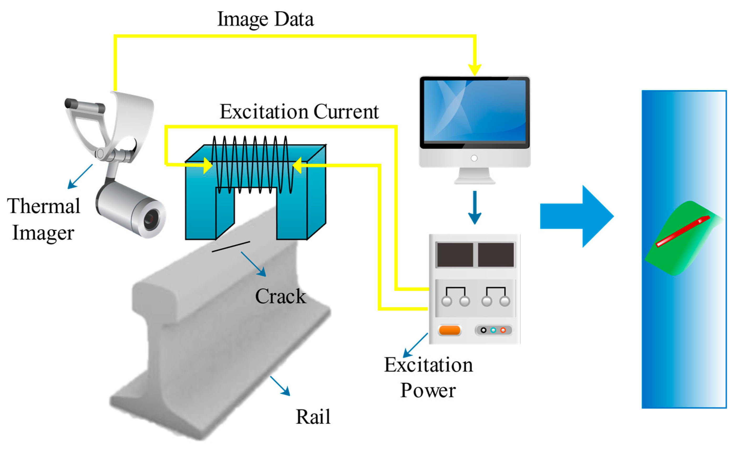
Eddy Current Pulsed ThermographySurface and near-surface defectsHas high detection resolution, rich in transient information, and is suitable for rapid non-contact detection.
Barkhausen Noise Surface defectsCan detect stress magnitude, fatigue life, and microstructure such as small cracks.
Machine visionMachine visionLarge surface defectsCan detect abrasion, stripping. Difficult to detect surface closed microcracks and internal defects.
Publisher’s Note: MDPI stays neutral with regard to jurisdictional claims in published maps and institutional affiliations.

