Article

Experimental Study on Fatigue Performance of Welded Hollow Spherical Joints Reinforced by CFRP

College of Civil Engineering, Taiyuan University of Technology, Taiyuan 030024, China
*
Author to whom correspondence should be addressed.
Coatings 2022, 12(10), 1585; https://doi.org/10.3390/coatings12101585
Submission received: 26 September 2022 / Revised: 14 October 2022 / Accepted: 18 October 2022 / Published: 20 October 2022

Abstract

:
The risk of fatigue failure of welded hollow spherical joints (WHSJs) under alternating loads increases due to the inherent defects, the disrepair, and the demand for tonnage upgrades, of suspension cranes. The finite element analysis results revealed that the ranking of the stress concentration factor at the WHSJ was as follows: weld toe in steel tube of tube–ball connection weld > weld toe in steel tube of tube–endplate connection weld > weld toe in sphere of tube–ball connection weld > weld toe in plate of tube–endplate connection weld. Moreover, the peak stress at the weld of the tube–sphere connection was reduced by 32.93% after CFRP bonding reinforcement, which was beneficial for improving the fatigue performance. In this study, 16 full-scale specimens of Q235B WHSJs were tested by an MTS fatigue testing machine to study the strengthening effect of CFRP on the fatigue performance. It was found that the fatigue fracture of WHSJs was transferred from the tube–sphere connection weld to the tube–endplate connection after CFRP reinforcement. According to the fitted S-N curves, the fatigue strength could be increased by 13.26%–18.19% when the cycle number increased from 10,000 to 5,000,000.

1. Introduction

The welded hollow sphere joint grid structure has a simple structure, excellent mechanical properties, and unique advantages, especially in terms of construction cost [1]. As an important part of the grid structure, the welded hollow sphere joint (WHSJ) has been widely used in public buildings such as gymnasiums, exhibition centers, waiting halls, industrial buildings, industrial plants, hangars, and dry coal sheds, etc. [2].
With the development of industrialization, industrial buildings are faced with increasing volume demand and lifting equipment upgrades. The increases in suspension crane level, load, and use frequency, render welded hollow spherical joint grid structures more prone to fatigue damage. The damage positions are shown in Figure 1: the weld toe on the spherical surface of the steel pipe or cross-plate connection (①, ③), the weld toe on the pipe surface of the steel pipe connection (②), and the high-strength bolts for cross-plate–beam connections (④). In related research on the fatigue performance at the spherical weld toe of welded hollow ball joints, Lei [3] established the calculation formula of stress concentration factor (SCF) by means of the thin shell theory, with a numerical range of 2.38–3.09. Fatigue tests of 15 specimens were completed, and the allowable nominal stress amplitude with n = 2 × 10 6 was 31.4 MPa. Yan [4] determined the SCF using ANSYS finite element analysis and a static tensile test with a numerical range of 2.06–4.86. The fatigue test of 29 welded hollow ball full-scale specimens was carried out, and the allowable nominal stress amplitude with n = 2 × 10 6 was 22.3 MPa. Jiao et al. [5] took the cross-plate–welded hollow sphere joint connection as the research object, performed 25 welding ball fatigue tests, and obtained that the allowable nominal stress amplitude with n = 2 × 10 6 was 19.7 MPa. In a study of the weld toe in steel tubes, Zhang [6] performed a fatigue test on 38 specimens and used infrared thermography to predict the position of fatigue fracture. The allowable nominal stress amplitude with n = 2 × 10 6 was 56.96 MPa.
The experimental results above indicate that the allowable stress amplitude at the spherical weld toe of the WHSJ is only 19.7–31.4 MPa, which is lower than the lowest class Z14 (36 MPa) in the standard for the design of steel structures (GB50017-2017) [7]. The allowable stress amplitude at the weld toe of the steel pipe is 56.96 MPa, which is close to class Z10 (56 MPa) in GB50017-2017 [7]. This indicates that there are significant fatigue hazards in grid structures with such a low fatigue strength. However, the research on the reinforcement of WHSJ is more focused on the static performance [8,9,10,11], and the improvement of fatigue performance is rarely involved, which proved that research into improving its fatigue performance fundamentally is extremely urgent.
In studies on the fatigue performance of welding structures reinforced by CFRP, the test objects included butt joints in steel plates [12,13,14,15], cruciform welded joints [16,17,18,19], square pipe butt joints [20], K-shaped [21,22] and T-shaped [23] tube joints, and welded H-beams [24,25,26], which were characterized by a thick parent metal, relatively few weld defects, and an easy reinforcement operation. As shown in Table 1, the use of CFRP paste reinforcement could double the fatigue life or fatigue strength of components, and the reinforcement effect is remarkable. Compared with steel plates, the parent metal of WHSJ is a spherical surface, which results in more severe geometric discontinuities and stress concentration, whereas the effect of reinforcement with CFRP pasting is unknown. In this study, CFRP was applied to strengthen the welded hollow spherical joints, and the constant amplitude fatigue test of reinforced and unreinforced specimens was conducted. Based on the obtained S-N curves, the fatigue designing method was proposed and the effects of reinforcement were discussed, laying a foundation for the improvement of the fatigue performance of in-service welded hollow sphere grid structure joints.

2. Stress Concentration Analysis
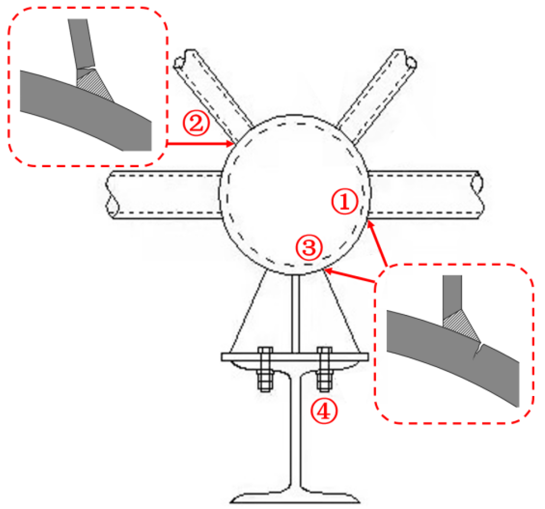
2.1. SCF of WHSJ

In order to obtain the stress distribution state of the nodes in the welded hollow spherical joint grid structure, an FE model with the size of the specimen from Zhang [6] (specification 1, where the hollow ball is stronger than the tube) was built to analyze the stress concentration. A tensile surface load of 1 N/mm2 was applied to the top of the joint. The calculation results revealed four parts with significant stress concentration in this type of WHSJ (Figure 2). Under the same load, severe stress concentration appeared on the weld toe in the steel tube, due to the tube–sphere connection weld (Location 1) and tube–endplate connection weld (Location 3), with a maximum stress of 5.69 and 5.45 MPa, respectively. On the other hand, the SCF of the weld toe in the sphere (Location 2) and endplate (Location 4) was smaller, with a maximum stress of 4.25 and 0.72 MPa, respectively. Under the action of cyclic load, fatigue failure first occurred at Location 1, followed by Location 3, Location 2, and Location 4, which is consistent with the test failure locations. Therefore, the primary reinforcement area for the fatigue performance of WHSJs would be the weld toe in the steel pipe of the tube–ball connection weld, while the secondary area of concern would be the weld toe in the steel pipe of the tube–endplate connection weld.

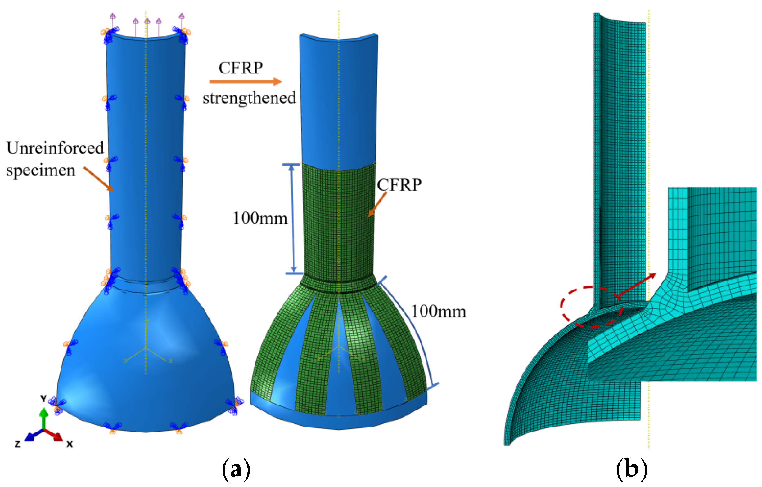
2.2. SCF of CFRP-Strengthened WHSJ
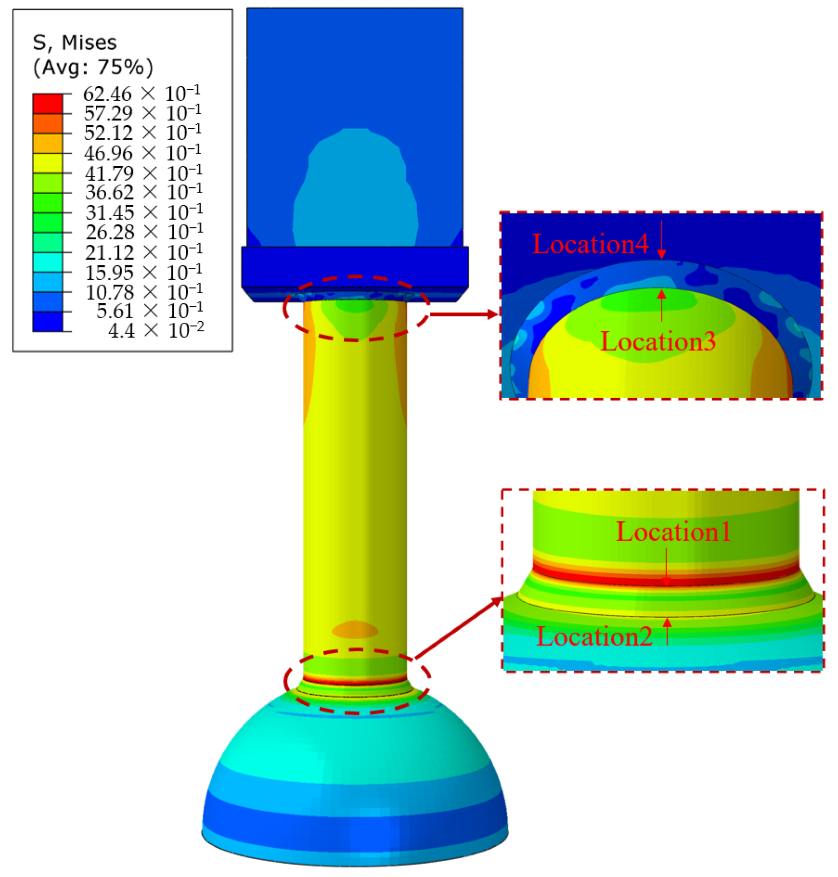
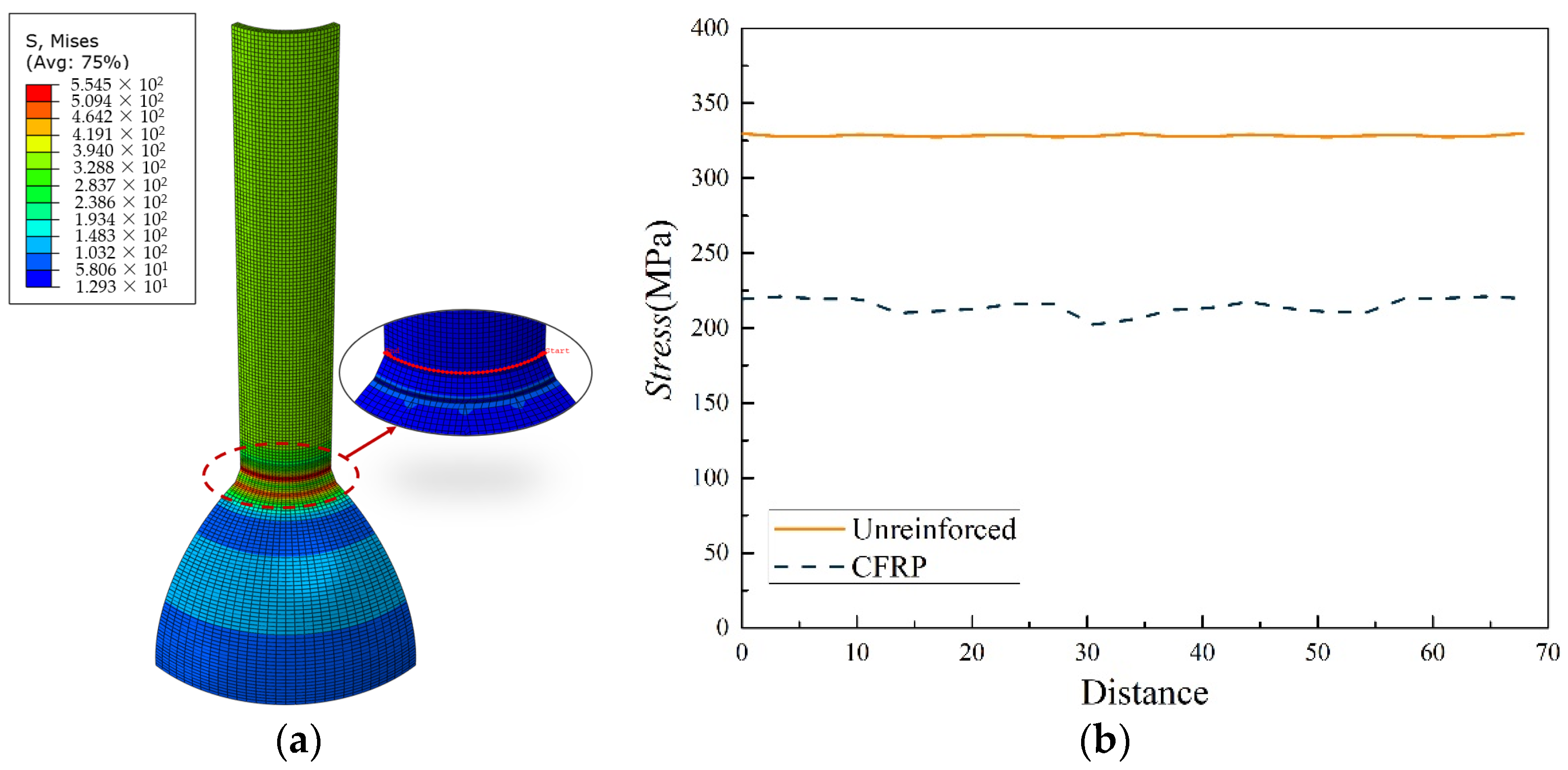
The basic principle of the fatigue performance of the welded structure reinforced with CFRP is to change the force transmission path of the original structure, such that part of the load is borne by CFRP, thereby reducing the stress state of the reinforced part. Research results have shown that CFRP can effectively reduce the SCF at the weld toe, which decreases significantly with the increase in the number of carbon cloth layers [22]. As shown in Figure 3a, taking account of the symmetry of WHSJs, only one-eighth of the tube–spherical joints were analyzed, where the vertical boundaries of the sphere and the tube surface were fixed constraints. An axial tensile surface load of 150 MPa was applied to the end of the steel tube, and a single layer of CFRP was arranged in the range of 100 mm above and below the weld of the tube–sphere connection. Welds, pipes, and hollow balls used the same material parameters, with an elastic modulus of 206 GPa and a Poisson’s ratio of 0.3. The mesh types of CFRP and steel products were M3D4R and C3D8I, respectively, and the mesh at the weld toe of the tube–ball connection was encrypted (Figure 3b).

2.3. FEA Results

Under the action of the axial tensile surface load (Figure 4a), the stress concentration at the weld toe of the original tube–sphere joint was the most severe. The calculation results of Von Mises stress at the weld toe extracted along the circumferential direction are shown in Figure 4b. The maximum stress at the weld toe of the unreinforced WHSJ was 329.8 MPa, which changed to 221.2 MPa when reinforced by CFRP, representing a 32.93% reduction in maximum stress. The finite element analysis results show that CFRP bonding could improve the stress concentration at the weld toe, thereby improving its fatigue performance.

3. Experimental Program

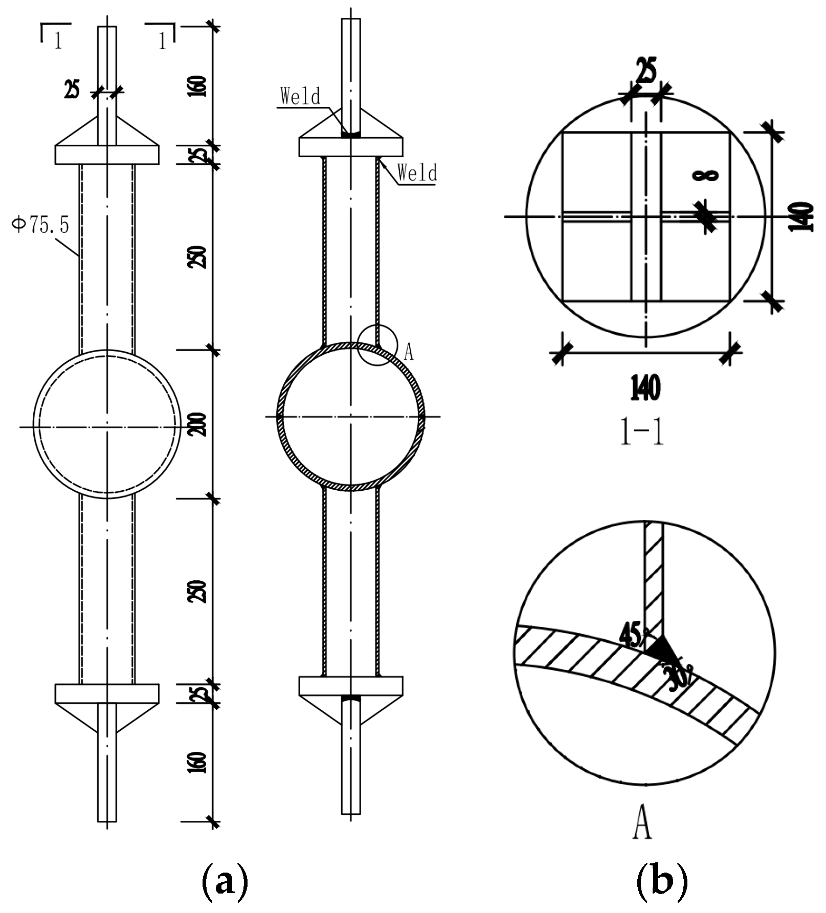
3.1. Specimen Design

A total of 16 WHSJ fatigue tests were carried out, including four unreinforced specimens and 12 CFRP-reinforced specimens. Technical specifications for space frame structures (JGJ 7-2010) [27] stipulate that the ratio of the outer diameter D of the welded hollow sphere (WSH) to the outer diameter d of the steel pipe in the grid structure should be 2.4–3.0, the ratio of the wall thickness of the hollow sphere t to steel tube t c should be 1.5–2.0, and the ratio of D to t should be 25–45. According to the requirements of the specification, the material of the test piece was selected as Q235B, while the pipe was high-frequency welded with a diameter of 75.5 mm and a thickness of 3.75 mm. The diameter of the hollow sphere was 200 mm, and its thickness was 8 mm. The welding grades were no lower than second grade; the parameters of the specimen are shown in Figure 5. Grade I carbon fiber cloth and matching impregnating adhesive produced by Carbon Composites Co., Ltd. (Tianjin, China) were selected as the reinforcement material; its mechanical properties are shown in Table 2.

3.2. Visual Examination

3.2.1. Size Recheck

The sphere thickness t , tube outer diameter d , and thickness t c of all specimens were measured using an ultrasonic thickness gauge and vernier caliper. The provisions in the standard for the acceptance of construction quality of steel structures (GB 50205-2020) [28] and welded steel tubes for general construction (SY/T 5786-2016) [29] indicate that the allowable deviation of the thinning amount of the ball wall thickness is a minimum of 0.18 t , 1.5 mm if t 10 , while the allowable deviation of d is ± 1 %   d when 60.3 d < 355.6 and that of t c is ± 10 %   t c when 3 t c < 12 . The test results are shown in Table 3. The wall thickness reductions of the welding ball and pipe size in this batch of specimens were within the allowable range of the specification; thus, they were considered acceptable.

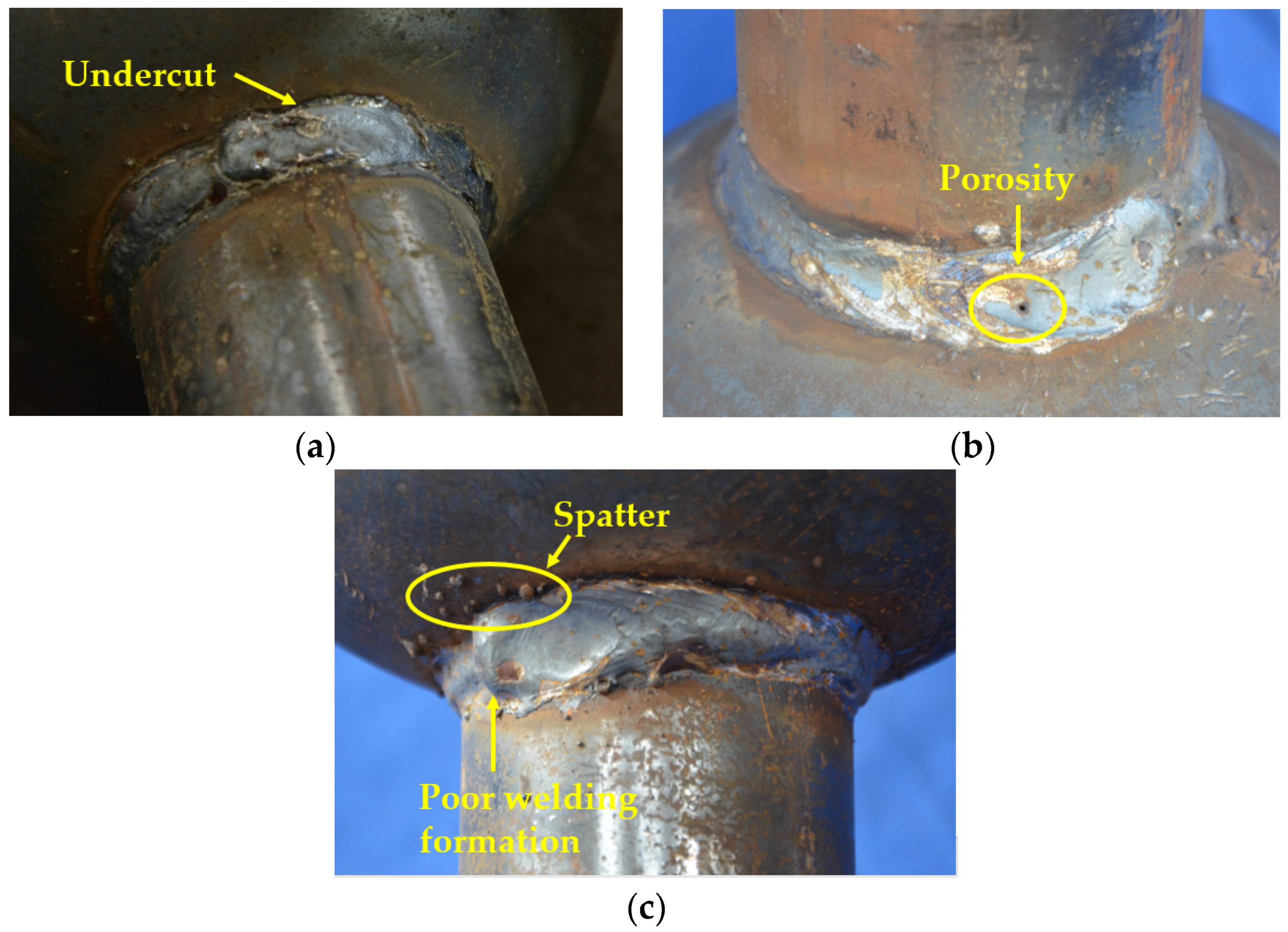
3.2.2. Weld Appearance
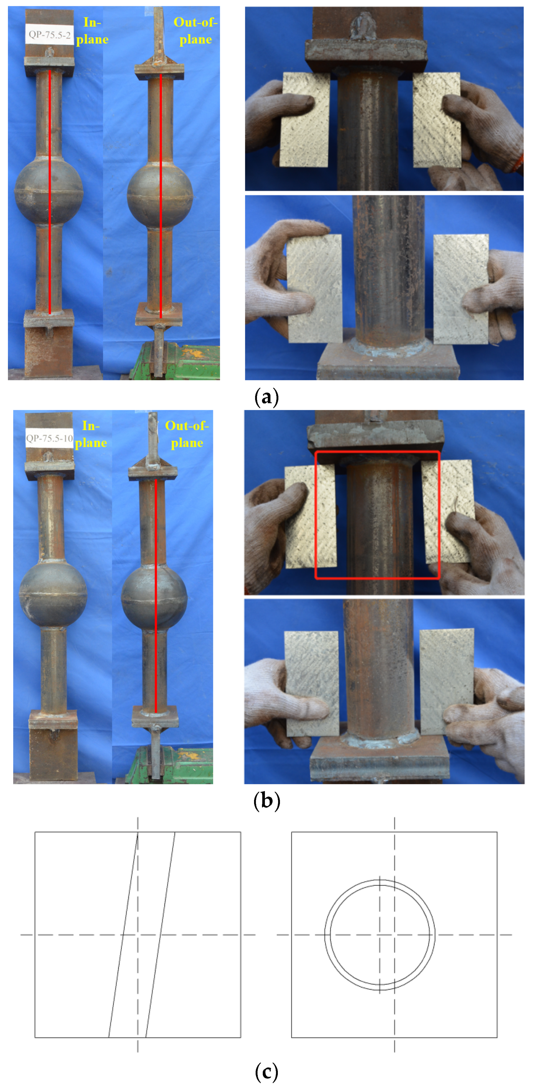
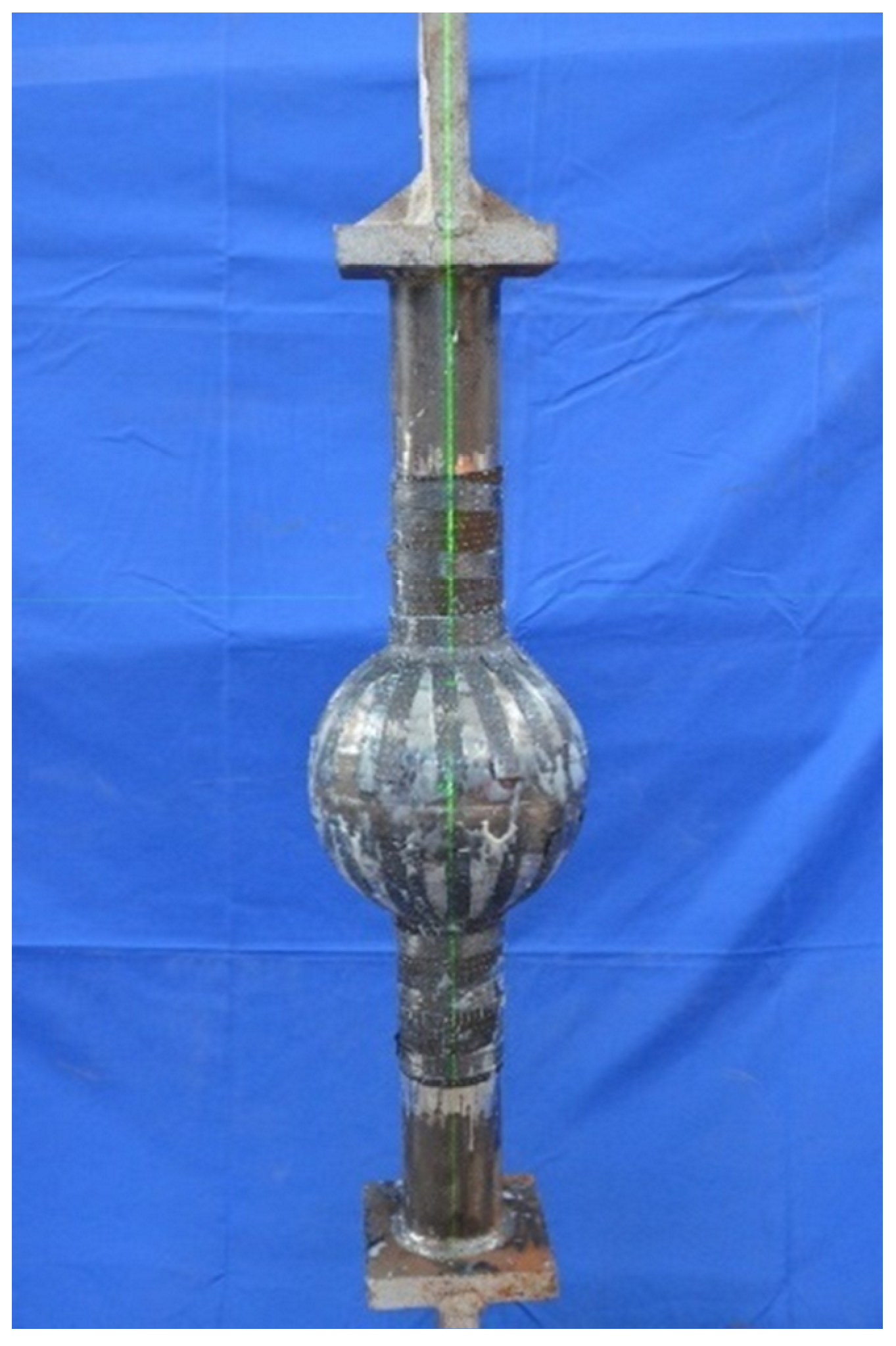
JGJ 7-2010 [27] stipulates that tube–sphere butt welds should be second grade, and that all welds should be subject to visual inspection. GB 50205-2020 [28] specifies that no cracks, incomplete welding, root shrinkage, arc scratches, poor joints, pores, or slag inclusions are allowed in the appearance of secondary welds that require fatigue checking. On the other hand, undercut is allowed if its length is less than a minimum of 0.05 t, 0.3 mm or its continuous undercut length is 100 mm and both sides of the weld undercut total length are ≤10% of the weld.
This batch of test pieces was assembled manually by welding in the factory, truly simulating the on-site construction process of welding hollow spheres. The appearance checking results of the welds in all the test pieces in accordance with the above provisions are shown in Figure 6, highlighting that the welds of individual specimens had more or less apparent defects such as undercut and poor joints. The results of the weld survey showed that the construction quality of the welded hollow ball grid structure was uneven, especially for the in-service structures which were built at a poor construction level; the welding quality was possibly not up to standard but still functional.

3.2.3. Coaxiality

A large number of manual operations relating to the welded hollow spherical grid structure can easily lead to angle deviation between the branch pipe and the spherical joint during the production process, such that the node domain is not completely in the state of absolute axial force. The additional bending moment generated by the eccentricity of the branch pipe has a great influence on the fatigue strength of the structure. As shown in Figure 7, the analysis of the tube–sphere coaxiality of the specimen revealed the following problems in this batch of specimens:
(1)
In-plane and out-of-plane tilt of branch pipe,
(2)
Branch pipe not perpendicular to endplate,
(3)
Projection line of the chuck on endplate surface not perpendicular to endplate edge,
(4)
Branch pipe centroid not coinciding with endplate centroid.

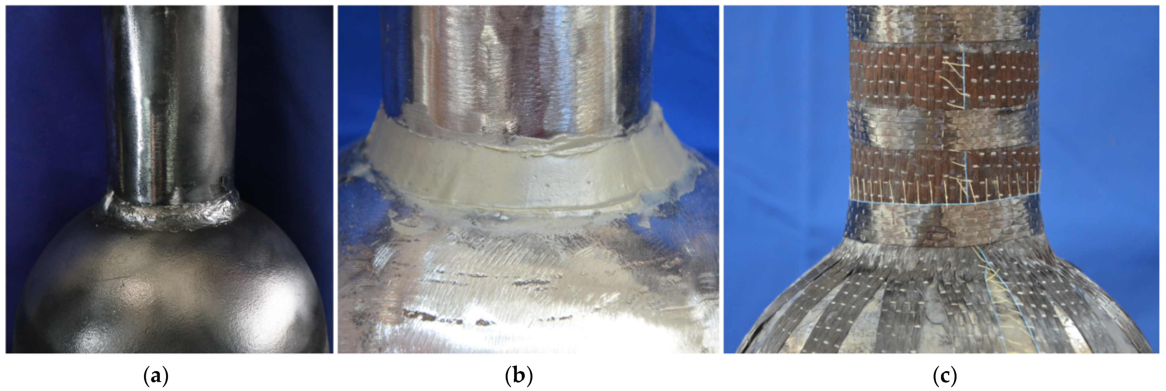
3.3. Specimen Construction
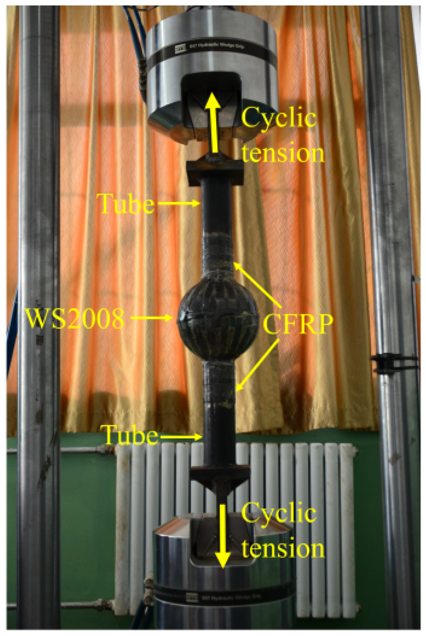
This batch of specimens was divided into two categories: a nonreinforced welding ball control group (hereinafter referred to as the ‘control group’), and a CFRP-reinforced welding ball experimental group. According to the census results of the appearance of the specimens, they were divided into qualified specimens (‘experimental group A’) and unqualified specimens (‘experimental group B’). The two types of specimens whose initial states were close to each other were tested for comparison. The specimens in the control group were only polished and smoothed on the surface and sprayed with black matte paint, and the specimens in the experimental group were reinforced on the basis of the control group.
The reinforced part was ground until the metallic luster was exposed, and then steel glue was used to screed the weld surface to make it as smooth as possible. Then, special CFRP impregnating glue was configured according to the proportions and painted evenly on the surface of the test piece. Finally, the carbon cloth and test piece were tightly pasted together, pressing for 10–15 min. The production process and finished product are shown in Figure 8 and Figure 9.

3.4. Loading Scheme

The instruments used in the test were an MTS Landmark370.50 fatigue testing machine and the supporting test system MTS MPE. The maximum displacement loading measurement accuracy of the test machine was 0.00028 mm, the load range was ±15–500 N, and the maximum loading frequency was 100 Hz. This machine can perform sinusoidal, triangular, square wave, custom waveform, and load spectrum fatigue loading. The clamping diameter of the test fixture was in the range of 25–55 mm, meeting the design requirements of this study (Figure 10).
The stress amplitude Δ σ of the lower chord member near the suspension point in the welded hollow spherical grid structure with a suspension crane was the largest; the stress ratio ρ of the fatigue test was set as 0.1. According to the design strength of Q235 steel [7], the maximum stress σ m a x in this test was 215 MPa. The lower chord was controlled by the dead load, and the stress was relatively large under the static state. Therefore, the minimum stress σ m i n in this test was determined to be 130 MPa; the loading scheme is shown in Table 4.

4. Results and Discussion
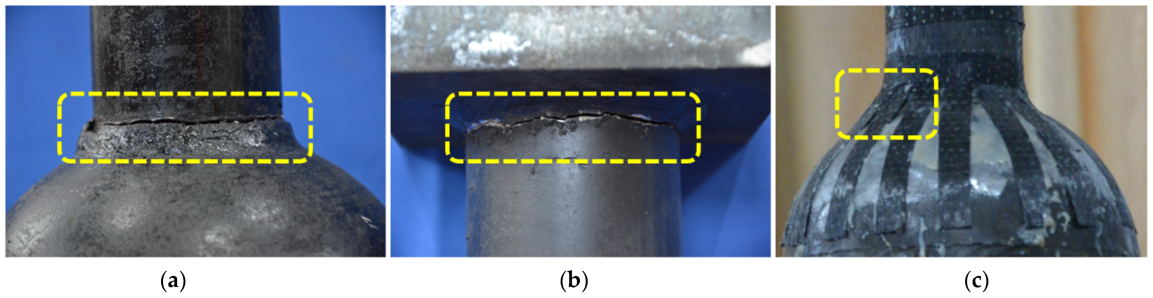
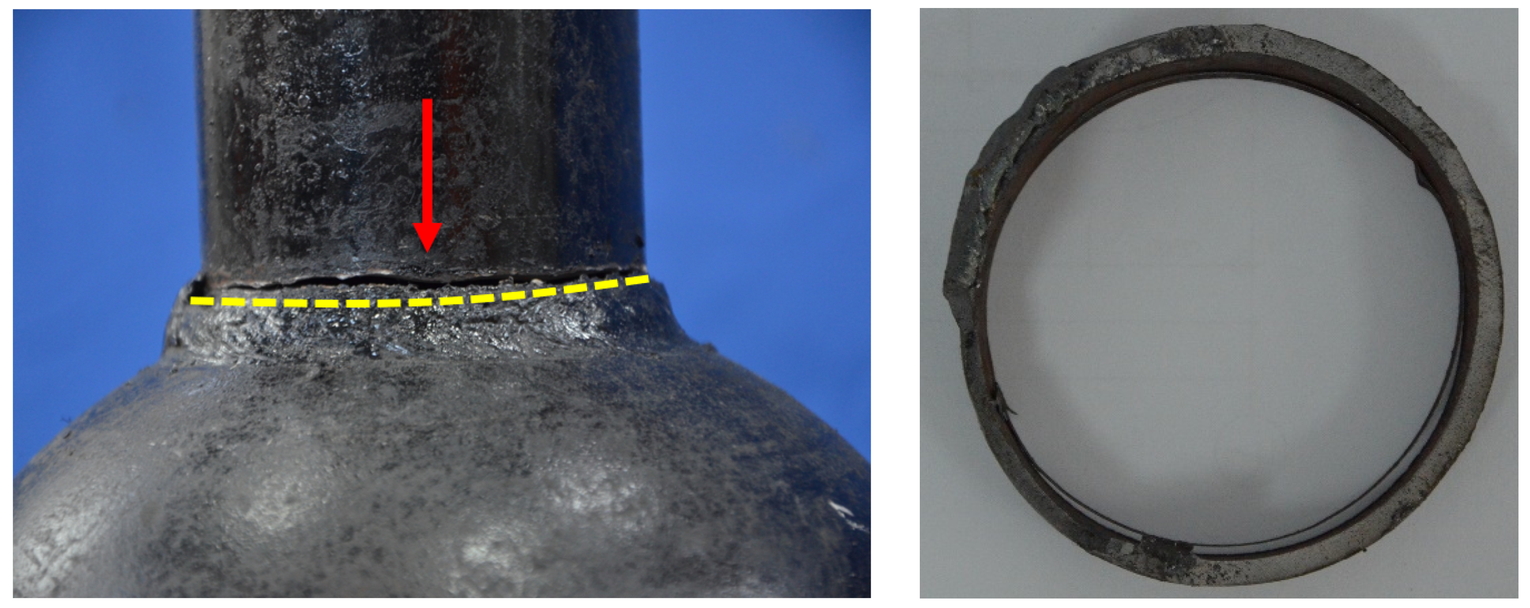
4.1. Failure Mode

A total of 16 experimental data were obtained from QP-76, including four data in the control group and 12 data in the experimental group. As shown in Figure 11, the test results of the control group were consistent with the finite element analysis, and the fatigue fractures were all generated at Location 1, being recorded as failure mode 1. The fatigue failure modes of the specimens in the experimental group were divided into two categories. Experimental group A was consistent with the finite element analysis results, with fracture occurring at Location 2. The fatigue life of the specimens was higher than that of the control group, being recorded as failure mode 2, and the test components were qualified specimens. The fracture location of experimental group B was the same as that of the control group, and the fatigue life of the specimen had no increase, being recorded as failure mode 3; the test components were unqualified specimens.
Failure mode 1 (Figure 12) was the same as the test results of Zhang [6], occurring at the weld toe of the pipe surface. When the test was stopped, the fracture length basically accounted for half of the tube’s entire circumference. The crack originated from the undercut of the tube surface and completely penetrated along the wall thickness direction of the steel tube, before cracking circumferentially along the weld toe of the tube surface. The angle between the section and the horizontal plane was about 45° after the specimen was broken, and obvious fatigue sources could be observed on the fracture surface.
The fatigue failure position of the test piece in experimental group A was transferred from the tube–sphere connection weld to the pipe–endplate connection weld, and fracture occurred at the pipe surface weld toe, as seen in Figure 13. As shown in the FE analysis (Section 2.1), the most severe stress of WHSJ was concentrated at the weld of the tube–ball connection. After CFRP was used to strengthen the tube–sphere weld, the force transmission mode of the joints changed from ‘steel tube→weld’ to ‘steel tube→weld + CFRP’, which changed the stress field around the crack tip and reduced its stress intensity factor. Compared with the control group, the most severe stress of the component was then changed from the tube–ball connection weld to the tube–endplate connection weld, and the fatigue life was improved.
For experimental group B, the failure position of the specimen still occurred at the weld of the tube–sphere connection after reinforcement, similar to the control group. When the crack propagated, the CFRP and the weld were completely peeled off, thus negating the effects of the CFRP. Hence, the fatigue life was not improved compared with the control group.

4.2. Data Statistics

The relationship between the load and the fatigue life of a member can be described by the S-N curve, which is commonly represented by the following power function expression:
σ m N = C
where σ is the stress range and N is the fatigue life. C and m are fatigue constants that can be obtained through testing.
Taking the logarithm of both sides of Equation (1), the following expression can be obtained:
l g N = m l g σ + l g C
According to the Equation (2), taking the stress range Δ σ as the variable, the test life under different failure modes in the test results was fitted in the form of a power S-N curve and a double logarithmic l g σ l g N curve. The results are shown in Figure 14, Figure 15 and Figure 16. The fitting results of failure mode 1 and the calculation formula of the corresponding diagonal part at a 97.7% guarantee rate are as follows:
Δ σ 1 = 1190 × N 0.17
l g N 1 = 14.48 4.19 l g Δ σ 0.57
The corresponding expressions for failure mode 2 are as follows:
Δ σ 2 = 1650 × N 0.19
l g N 2 = 14.41 4.36 l g Δ σ 0.40
The corresponding expressions for failure mode 3 are as follows:
Δ σ 3 = 2185 × N 0.23
l g N 3 = 13.06 3.63 l g Δ σ 0.31

4.3. Contrastive Analysis

The test results showed that, for the qualified specimens, the failure position after CFRP reinforcement was transferred to the steel tube–endplate connection. Under the same stress amplitude, the fatigue life of the specimens after CFRP reinforcement could be increased by 17.36%–279.56%. Secondly, no fatigue failure occurred at the reinforcement position when the test stopped. The increase in fatigue life based on the test results was a conservative calculation result. Thirdly, the increase in fatigue life became greater for a larger loading stress amplitude, indicating a better reinforcement effect according to the test results. Lastly, the initial defects of unqualified specimens were obvious, and there were visible neutral deviations in the upper and lower branches in experimental group B. The appearance quality of the weld at the tube–ball joint of the specimen could not meet the requirements of the secondary weld, and the fatigue performance was not improved after CFRP reinforcement.
The test fitting curves are summarized in Figure 17. It can be obtained that after the fatigue failure position was transferred from Location 1 to Location 3, the fatigue strength of the qualified specimen was increased by 13.26%–16.94% between 10,000 and 1,000,000 cycles. Secondly, when the number of cycles reached 2,000,000, the fatigue strength increased by 17.48%. Lastly, when the number of cycles reached 5,000,000, the fatigue strength increased by 18.19%.
The verification test research carried out in this paper demonstrates that the use of CFRP to strengthen the fatigue performance was effective. Nevertheless, the reinforcement effect of CFRP on WSHJ is slightly lower than other welding forms.

5. Fatigue Design Method

Currently, the common fatigue design method is still based on the nominal stress amplitude method. Therefore, two types of fatigue design methods, including the weld toe in the steel pipe of WHSJ (Location 1), and tube–endplate connection (Location 3), were established according to the following formulas:
Δ σ n o m [ Δ σ ]
[ Δ σ ] = ( C n ) 1 / β
where Δ σ n o m represents the nominal stress amplitude of the steel pipe, and [ Δ σ ] is the allowable stress amplitude. C and β are the fatigue design parameters that need to be calculated, and n is the fatigue stress cycle number.
For failure mode 1, the fatigue design parameters at the weld toe in the steel tube of the tube–sphere connection were C = 7.998 × 10 13 and β = 4.188 , whereas they were C = 1.02 × 10 14 and β = 4.360 in failure mode 2. For the unqualified specimens in failure mode 3, these parameters were C = 5.60 × 10 12 and β = 3.626 . For the tube–ball joint weld, the lower limit of allowable stress amplitude of the qualified specimen with n = 2 × 10 6 as the base period and taking 97.7% survival probability was 65.35 MPa, whereas it decreased to 59.95 MPa for the unqualified specimen. For the tube–endplate connection weld, the lower limit of the allowable stress amplitude with the same base period and survival probability was 58.73 MPa, which is lower than the Z8 (71 MPa) of the flange–butt weld connection in the specification [7].

6. Conclusions

In this paper, a finite element simulation and experimental study were conducted to evaluate the fatigue performance of CFRP reinforcement in a welded hollow spherical joint grid structure, and the following conclusions were obtained:
(1)
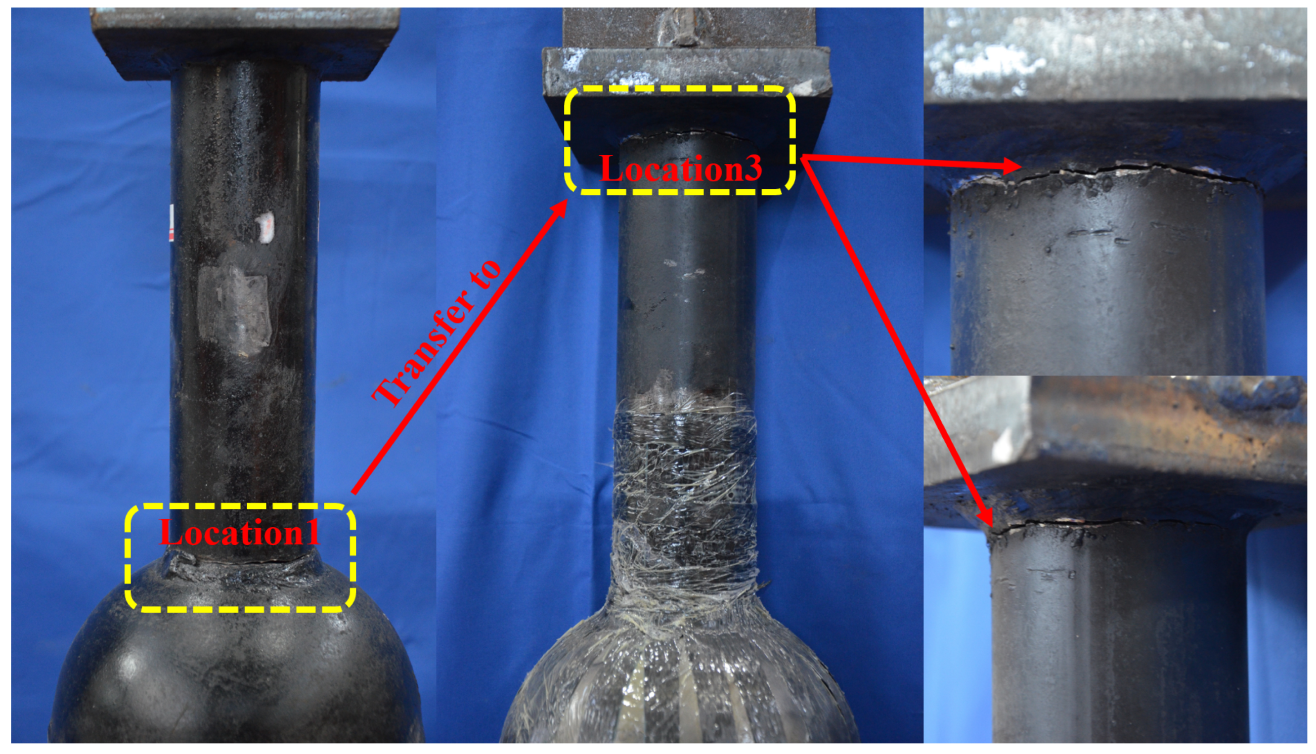
The ranking of the SCF at the weld toe of the WHSJs was as follows: weld toe in steel tube of tube–ball connection weld (Location 1) > weld toe in steel tube of tube–endplate connection weld (Location 3) > weld toe in sphere of tube–ball connection weld (Location 2) > weld toe in plate of tube–endplate connection weld (Location 4). The maximum stress at Location 1 was reduced by 32.93% after CFRP pasting.
(2)
The fatigue fracture of the unreinforced WHSJ occurred at Location 1, whereas the failure position was transferred to Location 3 after reinforcement, which was consistent with the finite element simulation results.
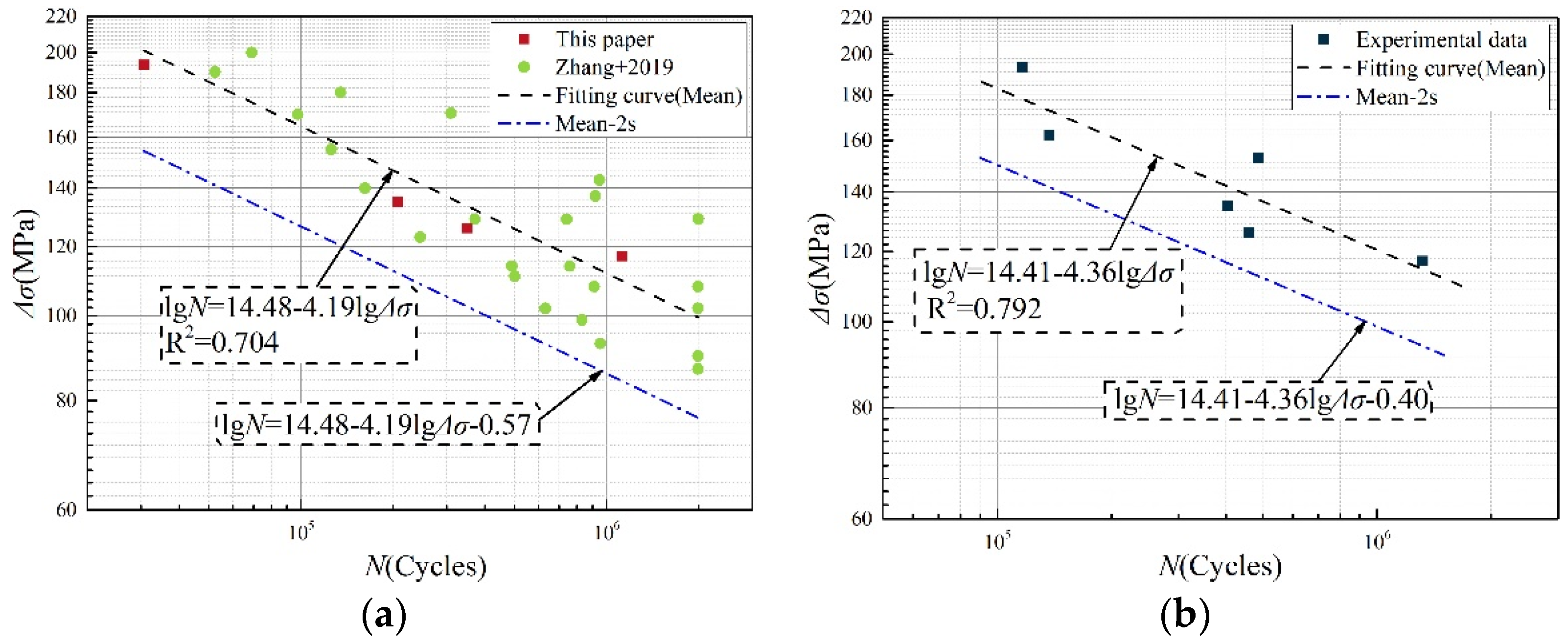
(3)
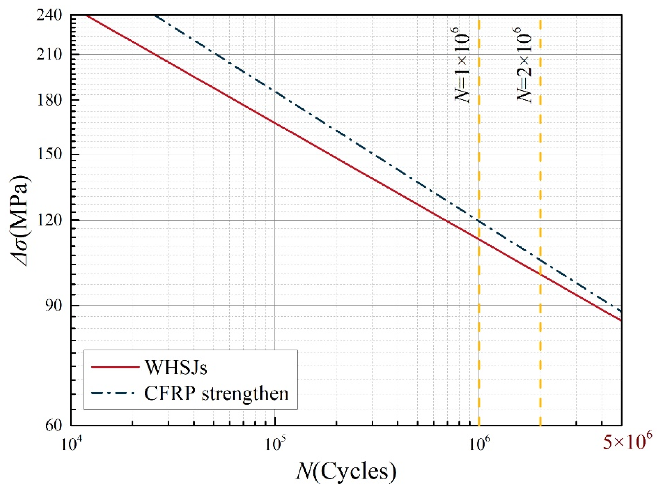
The S-N curves at the weld toe of the WHSJs before and after reinforcement were as follows:
l g N 1 = 14.48 4.19 l g Δ σ 0.57 ,   R 2 = 0.704 .
l g N 2 = 14.41 4.36 l g Δ σ 0.40 ,   R 2 = 0.792 .
Taking n = 2 × 10 6 as the reference period, the lower limit of allowable stress amplitudes under 97.7% survival probability were 65.35 MPa and 58.73 MPa, respectively.
(4)
No fatigue failure appeared in the reinforced area of WHSJs. Thus, the increase in fatigue life of WHSJs was conservative on the basis of the test results.

Author Contributions

Conceptualization, Y.D. and H.L.; methodology, Y.D.; software, Y.D.; validation, Y.D. and S.J.; resources, S.J.; data curation, Y.D.; writing—original draft preparation, Y.D.; writing—review and editing, H.L.; visualization, Y.D.; supervision, H.L. and S.J.; project administration, Y.D. and S.J.; funding acquisition, H.L. All authors have read and agreed to the published version of the manuscript.

Funding

This research was funded by National Nature Science Foundation of China grant number No. 51578357 and No. 52278198.

Institutional Review Board Statement

Not applicable.

Informed Consent Statement

Not applicable.

Data Availability Statement

Not applicable.

Conflicts of Interest

The authors declare no conflict of interest.

References

  1. Liu, X. Present situation in development of planar space grid structures in China. Steel Constr. 1994, 9, 13–20. (In Chinese) [Google Scholar]
  2. Lei, H. Research status and trend of welded hollow spherical joints grid structures. In Proceedings of the Sixth Annual Conference of Spatial Structure of Chinese Society of Civil Engineering, Beijing, China, 2–6 December 1992; p. 5. (In Chinese). [Google Scholar]
  3. Lei, H. Research on static and fatigue behaviour of welded hollow spherical joints in space trusses. J. Build. Struct. 1993, 14, 2–7. (In Chinese) [Google Scholar]
  4. Yan, Y. Theory Analysis and Testing Study on Fatigue Properties of the Steel Pipe-Welded Hollow Spherical Joints in Space Latticed Structure; Taiyuan University of Technology: Taiyuan, China, 2013. (In Chinese) [Google Scholar]
  5. Jiao, J.F.; Lei, H.G.; Chen, Y.-F. Experimental Study on Variable-Amplitude Fatigue of Welded Cross Plate-Hollow Sphere Joints in Grid Structures. Adv. Mater. Sci. Eng. 2018, 2018, 8431584. [Google Scholar] [CrossRef] [Green Version]
  6. Zhang, J. Experimental and Theoretical Research on Constant Amplitude Fatigue Properties of Weld Toe in Steel Tube of Welded Hollow Spherical Joints in Grid Structures; Taiyuan University of Technology: Taiyuan, China, 2019. (In Chinese) [Google Scholar]
  7. GB 50017-2017; Standard for Design of Steel Structures. China Architecture and Building Press: Beijing, China, 2017. (In Chinese)
  8. Xu, X.; Shu, T.; Zheng, J.; Luo, Y. Experimental and numerical study on compressive behavior of welded hollow spherical joints with external stiffeners. J. Constr. Steel Res. 2022, 188, 107034. [Google Scholar] [CrossRef]
  9. Zang, Q.; Liu, H.; Li, Y.; Chen, Z.; Li, X. Mechanical properties of welded hollow spherical joints reinforced with external ribs under axial tension. Spat. Struct. 2022, 28, 71–78. (In Chinese) [Google Scholar]
  10. Li, X. Study on Welded Hollow Spherical Joints Strengthened while Under Load; Tianjin University: Tianjin, China, 2021. (In Chinese) [Google Scholar]
  11. Li, C. Experimental Research and Finite Element Analysis on the Welded Hollow Spherical Joints Strengthened by Steel Thimble out Side the Ball; Tianjin University: Tianjin, China, 2021. (In Chinese) [Google Scholar]
  12. Chen, T.; Huang, C.; Hu, L.; Song, X. Experimental study on mixed-mode fatigue behavior of center cracked steel plates repaired with CFRP materials. Thin-Walled Struct. 2019, 135, 486–493. [Google Scholar] [CrossRef]
  13. Zhao, E. Testing Analysis of Fatigue Durability of Welded Steel Structures Reinforced by CFRP; Hefei University of Technology: Hefei, China, 2011. (In Chinese) [Google Scholar]
  14. Zhang, N.; Yue, Q.R.; Yang, Y.X.; Hu, L.Q.; Peng, F.M.; Cai, P.; Zhao, Y.; Wei, G.Z.; Zhang, Y.S. Research on the fatigue tests of steel structure member reinforced with CFRP. Ind. Constr. 2004, 4, 19–21. (In Chinese) [Google Scholar]
  15. Tong, L.; Yu, Q.; Zhao, X.-L. Experimental study on fatigue behavior of butt-welded thin-walled steel plates strengthened using CFRP sheets. Thin-Walled Struct. 2020, 147, 106471. [Google Scholar] [CrossRef]
  16. Jie, Z.; Wang, K.; Liang, S. Residual stress influence on fatigue crack propagation of CFRP strengthened welded joints. J. Constr. Steel Res. 2022, 196, 107443. [Google Scholar] [CrossRef]
  17. Chen, T.; Zhao, X.L.; Gu, X.L.; Xiao, Z.G. Numerical analysis on fatigue crack growth life of non-load-carrying cruciform welded joints repaired with FRP materials. Compos. Part B Eng. 2014, 56, 171–177. [Google Scholar] [CrossRef]
  18. Jie, Z.; Wang, W.; Fang, R.; Zhuge, P.; Ding, Y. Stress intensity factor and fatigue analysis of cracked cruciform welded joints strengthened by CFRP sheets considering the welding residual stress. Thin-Walled Struct. 2020, 154, 106818. [Google Scholar] [CrossRef]
  19. Chen, T.; Yu, Q.Q.; Gu, X.L.; Zhao, X.L. Study on fatigue behavior of strengthened non-load-carrying cruciform welded joints using carbon fiber sheets. Int. J. Struct. Stab. Dyn. 2012, 12, 179–194. [Google Scholar] [CrossRef]
  20. Amraei, M.; Jiao, H.; Zhao, X.L.; Tong, L.W. Fatigue testing of butt-welded high strength square hollow sections strengthened with CFRP. Thin-Walled Struct. 2017, 120, 260–268. [Google Scholar] [CrossRef]
  21. Tong, L.; Xu, G.; Zhao, X.L.; Yan, Y. Fatigue tests and design of CFRP-strengthened CHS gap K-joints. Thin-Walled Struct. 2021, 163, 107694. [Google Scholar] [CrossRef]
  22. Mohamed, H.S.; Zhang, L.; Shao, Y.B.; Yang, X.S.; Shaheen, M.A.; Suleiman, M.F. Stress concentration factors of CFRP-reinforced tubular K-joints via Zero Point Structural Stress Approach. Mar. Struct. 2022, 84, 103239. [Google Scholar] [CrossRef]
  23. Xiao, Z.; Zhao, X.L.; Mashiri, F.R.; Xu, B. Fatigue Experiments on CFRP Repaired Welded Thin-Walled Rhsto-Rhs Cross-Beam Connection. In Proceedings of the 10th International Symposium on Structural Engineering for Young Experts (ISSEYE10), Changsha, China, 19–21 October 2008; pp. 971–978. [Google Scholar]
  24. Wang, J. Research on Fatigue of Steel Crane Beam Strengthened with CFRP; Shijiazhuang Tiedao University: Shijiazhuang, China, 2021. (In Chinese) [Google Scholar]
  25. Zhao, F. FE Analysis of Welded Steel Beam Strengthened by CFRP; Hefei University of Technology: Hefei, China, 2009. (In Chinese) [Google Scholar]
  26. Xu, S. Research of the Fatigue Test of Welded Steel Structure Reinforced by CFRP; Hefei University of Technology: Hefei, China, 2008. (In Chinese) [Google Scholar]
  27. JGJ-2010; Technical Specification for Space Frame Structures. China Architecture and Building Press: Beijing, China, 2010. (In Chinese)
  28. GB 50205-2020; Standard for Acceptance of Construction Quality of Steel Structures. China Planning Press: Beijing, China, 2020. (In Chinese)
  29. SY/T 5768-2016; Welded Steel Tubes for General Construction. National Energy Administration: Beijing, China, 2016. (In Chinese)
Figure 1. Schematic diagram of fatigue failure location. (①) Spherical surface of the steel pipe connections; (②) Pipe surface of the steel pipe connection; (③) Spherical surface of the cross-plate connection; (④) High-strength bolts.
Coatings 12 01585 g001
Figure 2. Results of stress concentration analysis.
Coatings 12 01585 g002
Figure 3. FE modeling process. (a) Finite element model; (b) Mesh division.
Coatings 12 01585 g003
Figure 4. FEA results. (a) Stress concentration; (b) Stress concentration.
Coatings 12 01585 g004
Figure 5. Size of specimens. (a) Front view; (b) Vertical view and welding details.
Coatings 12 01585 g005
Figure 6. Defects in weld appearance. (a) Undercut; (b) Porosity; (c) Spatter and poor welding formation.
Coatings 12 01585 g006
Figure 7. Coaxiality of specimen. (a) Tube ball basically centered, with endplate basically vertical. (b) Tube not centered and endplate not vertical. (c) Deviation of centroid of endplate and branch pipe.
Coatings 12 01585 g007
Figure 8. Strengthening process of specimens reinforced with CFRP. (a) Polishing (b) Screeding (c) Pasting.
Coatings 12 01585 g008
Figure 9. Specimen bonded with CFRP.
Coatings 12 01585 g009
Figure 10. Test setup.
Coatings 12 01585 g010
Figure 11. Typical failure mode of QP-76. (a) Failure mode 1 (b) Failure mode 2 (c) Failure mode 3.
Coatings 12 01585 g011
Figure 12. Failure mode 1.
Coatings 12 01585 g012
Figure 13. Failure mode 2.
Coatings 12 01585 g013
Figure 14. Power S-N curve fitting with Δ σ as variable. (a) Unreinforced specimen (b) Strengthened with CFRP.
Coatings 12 01585 g014
Figure 15. Double-logarithmic S-N curve fitting with Δ σ as variable. (a) Unreinforced specimen (b) Strengthened with CFRP.
Coatings 12 01585 g015
Figure 16. S-N curve of failure mode 3. (a) Power (b) Double logarithmic.
Coatings 12 01585 g016
Figure 17. Summary of fitting curves.
Coatings 12 01585 g017
Table 1. Fatigue performance improvement percentage of welded joint reinforced by CFRP.
Component TypeLife Improvement (%)
Butt joint418 [12]; 97.19 [13]
Cruciform welded joint57–66.5 [16]; 218 [19]
Tubular welded joint408.82 [20]; 138 [21]
Welded steel beam213.28 [24]; 93.7 [26]
Table 2. Mechanical properties of test materials.
MaterialElastic Modulus
(GPa)
Yield Strength
(MPa)
Tensile Strength
(MPa)
Elongation
(%)
CFRP2403512.71.7
Adhesive2.960.13.40
Tube20640751822.5
Table 3. Measurement results of specimen size (mm).
Test Pieces t d t c
Test ValueErrorUpperLowerErrorUpperLowerError
QP-767.28−9.04%76.1076.050.86%3.723.72−1.01%
Note: The size of the connecting steel tubes at both ends of the welding ball was measured and divided into an upper branch pipe and lower branch pipe according to the relative position.
Table 4. Constant-amplitude fatigue test loading system of QP-76.
Loading
Grade
N m a x N m i n σ m a x σ m i n Δ σ ρ
1181.7418.1721521.5193.50.1
2152.1515.22180181620.1
3143.7014.37170171530.1
4126.7912.68150151350.1
5118.3411.83140141260.1
6109.8910.99130131170.1
Note: N m a x and N m i n are the maximum and minimum loading forces, respectively. σ m a x   and   σ m i n are the nominal stress of the steel pipe where σ m a x = N m a x / A s and σ m i n = N m i n / A s . Stress range Δ σ = σ m a x σ m i n and ρ = σ m a x / σ m i n .
Publisher’s Note: MDPI stays neutral with regard to jurisdictional claims in published maps and institutional affiliations.

