Article

Effect of Working Pressure on Tribological Properties of Ce-Ti/MoS2 Coatings Using Magnetron Sputter

1
School of Mechatronics Engineering, Henan University of Science and Technology, No. 48 Xiyuan Street, Luoyang 471003, China
2
Henan Key Laboratory for Machinery Design and Transmission System, Henan University of Science and Technology, No. 48 Xiyuan Street, Luoyang 471003, China
3
Longmen Laboratory, No. 1 Keji Street, Luoyang 471000, China
*
Author to whom correspondence should be addressed.
Coatings 2022, 12(10), 1576; https://doi.org/10.3390/coatings12101576
Submission received: 23 September 2022 / Revised: 13 October 2022 / Accepted: 15 October 2022 / Published: 18 October 2022

Abstract

:
In preparing MoS2-based coatings by magnetron sputtering, the working pressure of the vacuum chamber directly affects the number and kinetic energy of sputtering particles, which causes a difference in coatings structure and performance. In this paper, MoS2 composite coatings with Ce and Ti binary doping were prepared by unbalanced magnetron sputtering technology, and the variation of composition, structure, and tribological properties of Ce-Ti/MoS2 coatings under different working pressures was studied. The results demonstrated that Ce and Ti doping improves pure MoS2 coatings. The Ce-Ti/MoS2 coatings reached the hardness of 9.02 GPa and the friction coefficient of 0.065 when working pressure was at 0.6 Pa. It was also observed that the deposition efficiency and wear rate reached the optimal value at 0.9 Pa. With the increase of working pressure, the columnar structure of the coating was coarse due to the change of kinetic energy and quantity of particles in the chamber. The intensity of the MoS2 (002) diffraction peak decreased, which eventually led to a poor lubrication effect and aggravated wear. This study provides technical guidance for preparing metal-doped MoS2 composite coatings with excellent mechanical and tribological properties.

1. Introduction

The solid lubrication coating prepared by physical vapor deposition (PVD) technology is widely used in aviation and aerospace fields due to its low friction coefficient and stable working state [1]. Unlike common oxide coating structures [2], MoS2 is a classic transition metal dichalcogenides (TMDs) with a sandwich lamellar structure. The two adjacent layers of MoS2 are connected by the weak van der Waals, consequently resulting in a low shear strength between the two layers [3]. Therefore, it provides superior lubrication performance in the sliding process and even achieves a super-smooth state at a specific scale [4]. However, the (100) and (110) planes of MoS2 is easily oxidized [5], showing poor wear resistance in the atmospheric environment, which limits the storage period of coating from preparation to the working environment. Currently, many rocket launch platforms are located offshore, so the oxidation resistance and corrosion resistance of the coating also need to be further improved.
In order to solve the problem that the tribological properties of coatings decrease significantly in the atmospheric environment, the PVD field mainly relies on doping to make improvements. At present, the preparation of MoS2 coatings by PVD is primarily through the doping of metal elements [6,7,8,9], metal compounds [10,11,12], and non-metallic elements such as C and N [13,14] to improve the bearing capacity and antioxidant performance. These doping methods can improve the loose structure of the coating itself and achieve the purpose of wear resistance and corrosion resistance. In addition to the commonly used metal-doped elements (Cr, Ti, Cu, Ni, etc.), the rare earth elements have active properties and can regulate the growth of the coating [15]. However, rare earth doping is mostly used to regulate the optical, electrical, magnetic, and insulating properties of materials in surface technology [16,17,18,19,20,21]. Reports on improving the mechanical and tribological properties of magnetron sputtering MoS2 coatings are rarely seen.
In addition, the quality of the coatings is affected by multiple parameters (sputtering power, target distance, matrix bias, deposition temperature, etc.). For example, W. Song used the biphase deposition method to prepare MoS2/Zr composite films at different temperatures and found that appropriate preparation temperatures (180~200 °C) give the films excellent tribological properties [22]. J. Park prepared MoS2 films with different RF power using the RF power supply, and the results showed that the RF power increased from 100 to 200 W, the thickness increased from 100 to 240 nm, and the surface resistance increased with the increase of RF power [23]. F. Bulbul used unbalanced magnetron sputtering equipment to study the effects of bias voltage and target current on the structure, mechanical properties, and tribological properties of MoS2-Ti composite films prepared by pulsed magnetron sputtering [24]. Prozhega, M. V. deposited MoS2 coatings under different bias voltages (−20 or +100 V) by magnetron sputtering, and observed that positive bias voltage increased the deposition rate [25]. These methods influence the growth mode of molybdenum disulfide crystal and optimize the coating preparation process.
It cannot be ignored that the working gas pressure in the working process of PVD equipment also plays a crucial role. In the process of sputtering material from the target to the matrix, sputtering particles will collide, reflect and offset. However, the increase or decrease of the pressure in the chamber affects the change of particle density to a certain extent, resulting in different energy of sputtering particles reaching the matrix, making the coatings growth pattern different. In addition, studies suggest that rare earths inhibit grain growth and coarsening and promote ordered growth of crystal arrangement in materials [26]. Therefore, this paper prepared unbalanced magnetron sputtering technology under different working pressure for Ce, Ti dual-doping MoS2 coatings, using a variety of characterization methods research, cross-section shape, nanomechanical properties, and friction and wear performance. Thus, the law and principle of parameter influence werevealed.

2. Materials and Methods

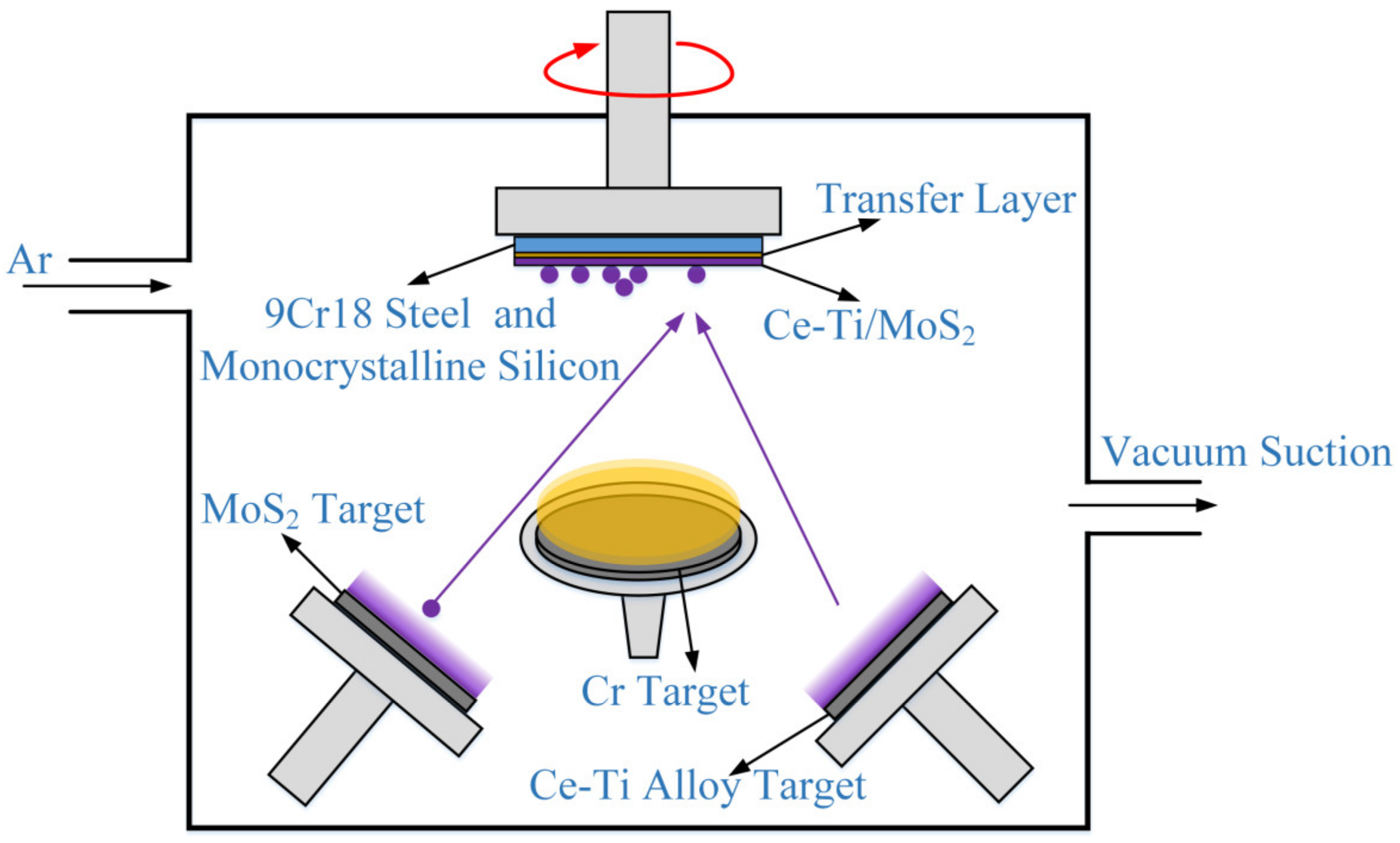
2.1. Preparation of Coatings

Ce-Ti/MoS2 composite coatings were deposited by a JGP045CA magnetron sputtering system produced by Shenyang Scientific Instrument Company (Shenyang, China). A MoS2 target with purity of 99.99% and Ce-Ti alloy target with atomic ratio of 1:1 were used as sputtering targets (target diameter of 50 mm and thickness of 3 mm). Monocrystalline silicon was used to test the mechanical properties and section images of composite coatings. In addition, 9Cr18 steel was used to test the friction, wear properties, and surface morphology of composite coatings. Before sputtering, the matrix was polished by water-soluble grinding paste on the cloth, cleaned with acetone and analytical ethanol for 15 min, then dried in a drying oven and put into a vacuum chamber. In order to improve the adhesion of Ce-Ti/MoS2 composite coatings, a 10 min Cr transition layer was deposited by 0.6 Pa on the substrate before Ce-Ti/MoS2 composite coatings were deposited. Then, Ce-Ti/MoS2 composite coatings were deposited at different working pressure by co-sputtering of the Ce-Ti alloy target and MoS2 target. The process parameters are shown in Table 1, and the deposition process is shown in Figure 1.

2.2. Morphology and Performance Characterization

The surface, cross-section, and wear morphology of Ce-Ti/MoS2 coatings were observed by FESEM (field emission scanning electron microscopy, Sigma300, ZEISS, Jena, Germany), and element analysis measurements were analyzed by EDS (Energy Dispersive Spectrometer), which is integrated on the FESEM. The crystal structure of the coatings was analyzed by GIXRD (grazing incidence X-ray diffractometer, Rigaku Smartlab 3 kW, Tokyo, Japan) with CuKα radiation, λ = 0.15405 nm, operating voltage and current were 40 kV and 40 mA; fixed incidence angle 1°, the scanning range was 5°–90°and the scanning rate was 5°/min. The composition of coatings was obtained by XPS (X-ray photoelectron spectroscopy, PHI-Vesoprobe 5000 III, Thermo Fischer, Waltham, MA, USA). The vacuum degree of the analysis room was 4 × l0−9 Pa with Al kαradiation (hv = 1486.6 eV). Working voltage and working current were 14.6 kV and 13.5 mA, respectively, and 20 cycles of signal accumulation. The passing energy was 20 eV; the step was 0.1 eV; the energy standard of C 1s = 284.8 eV was used for charge correction. The microhardness and elastic modulus of Ce-Ti/MoS2 composite coatings were analyzed by using the nano-indentation (iNano, KLA, Ann Arbor, USA). Berkovich indenter was selected to test the single point hardness on the monocrystalline silicon. In order to avoid the test error, five different positions were tested, the average value of the test results was taken, the test load was 10 mN, and the maximum indentation depth was set to be no more than 1/10 of the coating’s thickness.
The friction and wear properties of Ce-Ti/MoS2 composite coatings were tested on a friction and wear testing machine in the atmospheric environment. The friction mode was circular sliding friction under dry friction. The test conditions were as shown in Table 2.
The cross-section morphology of the wear marks was measured by the three-dimensional white light interference module of the UST-2 scratch instrument (Rtec, San Jose, CA USA); the wear area was obtained by integrating the profile. The wear volume was obtained by multiplying the total length of wear mark, and the wear rate (W) was calculated according to the formula [27]:
W = V F L
In the formula, W is the wear rate (mm3·N−1·m−1), V is the wear volume (mm3), F is the applied normal load (N), and L is the total friction stroke (m). The average value of the wear rate of three friction tests was calculated to reduce the error, and the wear rate was used as a measure of the wear performance of Ce-Ti/MoS2 composite coatings.

3. Results and Discussion

3.1. Coating Structure Characterization

The FESEM image of Ce-Ti/MoS2 composite coatings is shown in Figure 2, which is different from the wormlike surface morphology of pure MoS2 coatings shown in the literature [28,29,30]. After adding Ce and Ti, the surface forms the aggregation growth form of small protrusions, and there is a small gap between the protrusions, which is also reflected in the Ti/MoS2 composite coating [31]. Compared with the porosity of pure MoS2 coating [32], the dense protrusion growth mode is more compact and flat. The composite coatings show many of the small protrusions combined with individual large protrusions under different working pressure. The more significant protrusions may be related to the synergistic effect of impurities in the chamber and sputtering particles with different kinetic energy under different working pressure. When the working pressure is 0.6~1.2 Pa, the sputtered coatings are smoother, especially at 1.2 Pa. Small protrusions dominate the surface. With the increase of pressure, the uniformity of the coatings at 1.5~1.8 Pa is poor. In addition to the large-scale agglomeration structure that leads to many prominent protrusions on the surface, the protrusions in Figure 2e also become loose, and apparent gaps can be seen. Figure 3 shows the cross-section morphology of Ce-Ti/MoS2 composite coatings. It can be seen from Figure 3a,b that the cross-section of the coating is dense, and there is no obvious trace of columnar growth under the working pressure of 0.6~0.9 Pa. From 1.2 Pa, the coatings appeared to have columnar crystal growth. At this time, sputtering particle energy changes the coatings’ growth mode. when the working pressure increased, the columnar crystal became more loose, coarse, and porous, indicating that the bearing capacity of the coatings began to decline gradually. In addition, the columnar MoS2-based coatings are not conducive to reducing the sliding friction resistance, which is easier to be oxidized, resulting in reduced friction life [32].
Comparing the morphology image and the mapping test of the coatings’ surface by EDS, the atomic percentage of the coating chemical elements and the coatings’ thickness information are shown in Table 3. After Ce and Ti doping, the number of S elements in the coatings decreases sharply, and this is partly because the ionized S ions in the vacuum chamber will combine with the residual O and H ions and are easily pumped out by the pumping system of the vacuum chamber. On the other hand, due to the high emittance of the S element [33,34], the back sputtering after bombardment fails to attach to the substrate when it reaches the substrate. It is worth noting that although the 1:1 alloy target is used in the experiment, the content of the Ce element is significantly lower than that of the Ti element, indicating that the sputtering threshold of the Ce element is higher, resulting in relatively low sputtering efficiency of Ce element [35]. The S/Mo of the coatings decreases with the increase of working pressure. The main reason for this phenomenon is that the structure of the coatings is loose and columnar growth under high working pressure, and the burst leakage will be more easily oxidized in the air. Mo element is easy to combine with O to form Mo oxide [36], which reduces the relative content of the S element detected. In addition, the change of the coating thickness with pressure is very obvious. The minimum thickness is only 1.25 μm at 0.6 Pa, and the maximum is 2.8 μm at 0.9 Pa. The coating thickness decreases with the increase of pressure under other pressures. A large amount of argon in the chamber makes the target easier to glow and sputter, and the sputtered particles also increase. The particle density in the lower chamber decreases at low working pressure, and the mean free path increases due to the decrease in collision probability when the sputtered particles reach the substrate. This will cause the particle kinetic energy to be too high, so the particles reaching the matrix are reflected and challenging to adhere to. When the working pressure is too high (1.5~1.8 Pa), excessive collisions reduce the average kinetic energy when the sputtered particles reach the substrate. The coating thickness is reduced, and the coating structure is loose. The 0.9 Pa pressure parameter maximizes deposition efficiency and maintains a dense structure.
The GIXRD patterns of pure MoS2 coatings have obvious crystal structures [28,29,30], with characteristic peaks of 14.5°, 33.82°, 49.93° and 59.93°, corresponding to the (002), (100), (105), and (110) crystal planes of MoS2, respectively. The GIXRD diffraction pattern of the Ce-Ti/MoS2 composite coatings surface is shown in Figure 4. It can be seen that there are almost no obvious diffraction peaks in the Ce, Ti doped composite coatings. This shows that the doping elements make the original orderly growth of the crystal into a featureless growth form, becoming a similar amorphous structure. Although the peak width of the GIXRD pattern increases and the peak height is low under different working pressures, the diffraction peak of the (002) crystal plane belonging to MoS2 still exists, and the peak height is more obvious under low working pressure. According to the growth theory of TMDs materials [32], the (002) plane of type II MoS2 grows parallel to the substrate, which is beneficial for reducing friction resistance during the friction process. Therefore, it can be inferred that the coatings under low working pressure may have better friction and wear properties. Secondly, the peak of MoxSy (0.5 < x:y < 1) was found on the coatings (PDF card: No.51-1004, No.27-0319). The peak was 53.0° at 0.6 Pa, and the peak was 46.7° when the pressure was greater than 0.6 Pa. The possible structure was Mo7S8 and Mo3S4. From the S/Mo in Table 3, it can be seen that the cause of MoxSy may be related to the large loss of the S element. In addition, a small amount of CeO2 peaks were found in the coatings at 0.6 and 0.9 Pa, which may be caused by the different reaction products of Ce and the residual O element in the vacuum chamber.

3.2. Characterization of Mechanical Properties

Studies have shown that the higher the H/E value, the better the bearing capacity and fracture toughness of the coatings, and, to some extent, this reflects the wear resistance of the coatings [37,38]. As can be seen from Figure 5, due to the porous structure of pure MoS2, the microhardness is usually low. The doping of Ce and Ti significantly increases the coatings’ microhardness and improves the coatings’ bearing capacity. As the pressure increases, the coatings’ hardness gradually decreases from a maximum of 9.02 GPa at 0.6 Pa to 4.72 GPa at 1.8 Pa. It shows that the pressure significantly affects the energy of the sputtered particles to reach the substrate. Because of low pressure, the bombardment and re-sputtering caused by the high particle kinetic energy help to form a dense structure and improve the hardness. The hardness of the coatings decreases sharply when the pressure range is from 1.2 Pa to 1.5 Pa because the surface morphology (Figure 2) begins to change from fine and dense to coarse and loose after 1.2 Pa. According to the Hall–Petch theory [39], it is inferred that the grain boundary strengthening effect of coatings greater than 1.5 Pa is weakened, and the hardness is reduced. It can also be seen from Figure 5 that it decreases with the increase of H/E value pressure until it drops to about 0.049 under the parameters of 1.5~1.8 Pa. To a certain extent, the lower working pressure (0.6~0.9 Pa) has high hardness and improves the wear resistance. It is noteworthy that the elastic modulus has a certain specific increase when the working pressure is 1.2 Pa. Combined with the cross-sectional structure of Figure 3, the coatings began to grow in columnar crystals after 1.2 Pa. Due to the different growth directions of the coatings under different pressures, the elastic modulus detected by the nano-indentor also changed.

3.3. Tribological Performance Analysis

Friction coefficient curves at different deposition pressure are shown in Figure 6. It can be seen from the figure that Ce and Ti doped MoS2 composite coatings generally work under low friction coefficients below 0.1. It shows that the addition of Ce and Ti doping metals facilitates the compact coatings structure and retains the lubrication property of MoS2 itself. In terms of the fluctuation of the friction curve, the fluctuation range of 1.2~1.8 Pa is more extensive, and the fluctuation of the friction coefficient under 0.6 Pa pressure is the smallest. It is concluded that in addition to the thickness of the transfer film [40], the hard particles formed during friction also affect the coefficient change during friction [41]. From the friction curve values, the friction coefficient under low working pressure is small, the friction coefficient under 0.6 Pa pressure is stable at around 0.065 on average, and the 0.9 Pa coating can also be stable within 0.07 in the stable friction stage after 11 min. With the increase of working pressure (1.2~1.8 Pa), the friction coefficient almost reaches 0.1 in the late stage of friction. This is because the coatings start to grow along the vertical matrix when the working pressure is exceeds than 1.2 Pa, which is not conducive to reducing friction coefficient [42].
Three-dimensional morphology reconstruction of wear tracks is shown in Figure 7. The coatings abrasion area in the range of 1.8 × 1.1 mm2 was scanned to obtain the relative height information of the abrasion area. As shown in Figure 7, wear track is in the middle of the scan area, and debris accumulated in both sides of the wear track. The wear scars at 0.6 Pa and 0.9 Pa were smooth, and they became deeper when the working pressure increased to 1.2 Pa. Evident furrows began to appear on the surface of the wear scar at 1.8 Pa, which extension direction is parallel to the wear direction. In addition, there are traces of coating delamination at the edge of the wear scar.
Cross-section profiles andaverage wear rate are shown in Figure 8. From Figure 8 and Figure 9, it can be seen that the wear depths of 0.6 Pa and 0.9 Pa are 0.07 and 0.03 μm, respectively; the wear rates are 7 × 10⁻⁸ and 2.1 × 10⁻⁸ mm3·N−1·m−1, respectively. There is no obvious furrow in the cross-section profile of the wear scar. The wear depth reached 0.10 μm and 0.13 μm at 1.2 Pa and 1.5 Pa, respectively, and the wear rate gradually increased. In addition, the wear scar contour began to appear on many sawteeth, indicating the appearence of furrows and abrasive wear on the wear scar surface. It is worth noting that the coating under 1.8 Pa pressure not only has obvious wear traces, the wear rate reaches 23.7 × 10⁻⁸ mm3·N−1·m−1, and the edge of the wear trace also appears. The coating with a depth of about 0.2 μm fell off (Figure 7f). According to the morphology analysis, it is found that the columnar structure of the coating at 1.8 Pa is the coarsest, and the coating structure is loose. According to the analysis of mechanical properties, the hardness of the 1.8 Pa coating is small, and the relative elastic modulus is large, resulting in a smaller H/E value. Therefore, during the friction process of the coating, the cyclic action of the external force causes the coating to produce tiny cracks. When the crack grows to a sufficient length, it will peel off due to the stress generated by the extrusion of the steel ball. In studying the tribological properties of MoS2 coatings, Ti element doping has always been a hot topic. This study added the Ce element based on Ti doping to form binary doped MoS2-based coatings. They have similar friction coefficients compared to Ti/MoS2 coatings with similar composition, and even some Ti/MoS2 coatings have lower friction coefficients than Ce-Ti/MoS2 coatings [43]. However, in terms of wear resistance, Ce-Ti/MoS2 coating has more tremendous advantages, which is significantly better than the wear rate of 9.2 × 10⁻⁷ and 10−7 mm3·N−1·m−1 in the study of Li and Qin et al. [44,45].
Figure 10 shows the FESEM image and energy spectrum mapping results of the steel ball surface under various working pressures. It can be seen that the steel balls under various deposition parameters have traces of the transfer film. The soft transfer film has strong plastic flow and adhesion ability and can form good protection for the friction pair during the friction process [46], which is one of the reasons why the wear rate is not high under various working pressures. In addition to the attached transfer film on the dual steel ball, the wear scars (part of the red dotted coil) formed by the parallel arrangement of rubbing on the surface of the steel ball were also observed, among which the wear scar area was the smallest under the working pressure of 0.6 Pa and 0.9 Pa, and increased successively from the 1.2 Pa parameter, which also confirmed the changing trend of the coatings wear rate. According to the study of the friction of the coatings in the atmospheric environment [47], it was found that at the initial stage of the coatings wear, the nano-scale adsorption film formed at the friction interface reduced the friction coefficient, and the adhesion of the contact point after the adsorption film was destroyed caused the friction coefficient to increase. The alternation of formation and shedding of adsorption film causes both the fluctuation of the coefficient change and the accumulation of dense wear debris around the wear scar. Because the bearing capacity and deformation resistance of different materials with different deposition parameters are also different (as shown in Figure 5), the contact interface area increases with the working pressure at the initial friction stage. When the convex contact of the coatings surface is pushed and flattened, the excessive contact area increases the adhesion, resulting in a higher overall friction coefficient of the coatings under high working pressure. From the composition of the wear scar, the transfer film is mainly composed of Mo and S elements, which is the main component of the coatings; a small amount of Ti element was observed, and the Ce element was hardly observed. It shows that the friction process is not easy to transfer the Ce element and gather at the wear scar.
To further analyze the friction and wear differences caused by different working pressures, XPS was used to analyze the Mo 3d, S 2p, Ce 3d, and Ti 2p orbitals in the low pressure and high pressure samples, as shown in Figure 11. The peaks near 229.02 and 232.15 eV of (a) sample and 228.83 and 231.96 eV of (b) sample are referring to Mo 3d5/2 and Mo 3d3/2 for MoS2 [48], which are the main components that can reduce the friction coefficient in the coating. The peaks near 230.32 and 233.45 eV in (a) sample and 230.51 and 233.64 eV in (b) sample are Mo 3d5/2 and Mo 3d3/2 peaks in (MoO3) 0.50 (Fe2O3) 0.50 [49]. In addition, the peaks near 232.73 and 235.86 eV of (a) sample and 232.73 and 235.86 eV of (b) sample are Mo 3d5/2 and Mo 3d3/2 peaks in MoO3 [50]. It can be seen from these two peaks that Mo in the coating is mainly combined with S and O elements to form hard MoO3, which may aggravate wear [36]. The peaks near 162.36 and 163.54 eV on the S 2p orbital and 162.02 and 163.20 eV on the (b) sample are S 2p3/2 and S 2p1/2 peaks in MoS2, corresponding to the Mo 3d orbital results. In addition, the weaker MoOxS peaks near 163.73 and 164.91 eV on the (a) sample and 163.55 and 164.73 eV on the (b) sample. By and large, the peak intensity associated with MoS2 in the sample (a) is more obvious, and the peak intensity associated with Mo oxide is weaker; the peak value of bonding with Mo oxide in sample (b) is stronger than that in sample (a), indicating that the coatings are more seriously oxidized under high pressure.
The form of doping metal also affects the tribological properties of the coatings. As the content of doping elements, Ce and Ti are relatively small, the relatively obvious peaks are analyzed. The peaks near 882.23 and 900.33 eV of sample (a) in the Ce 3d energy spectrum orbit are the Ce 3d5/2 and Ce 3d3/2 peaks in CeO2; (b) Only the 882.19 eV peak on the sample is related to CeO2. In addition [51], the peaks of Ce2O3 were also found. The peaks near 886.42 and 904.52 eV of (a) sample and 885.50 and 903.60 eV of (b) sample were Ce 3d5/3 and Ce 3d2/3 peaks in Ce3+ [52]. The peaks near 458.78 and 464.32 eV on (a) sample and 458.84 and 464.38 eV on (b) sample are Ti 2p3/2 and Ti 2p1/2 peaks in TiO2 [53]. It can be seen that the doping element Ti is easy to combine with O under various parameters to form TiO2 dispersed in the coating. Ce element has the valence state of Ce3+ and Ce4+ in the coating. Ce4+ combines with oxygen to form CeO2. As an additive, it is beneficial to significantly reduce the friction coefficient and wear rate [54,55,56]. Ce3+ and oxygen form Ce2O3, which has the effect of removing impurities and refining grains [26,57]. In addition, it can also be seen that the relative content of CeO2 in (a) is higher than that in (b). Possibly due to pressure, Ce reacts with O2 and H2O in the vacuum chamber to form different oxides. The pressure affects the average kinetic energy of the Ce element in the sputtering state, which affects the oxidation products. It also shows that the higher content of CeO2 under low pressure may be more likely to reduce friction.

4. Discussion

Combined with the above tests and analysis, the wear mechanism of the 9Cr18 steel balls on Ce-Ti/MoS2 coatings is speculated, as shown in Figure 12. First, before the friction behavior, as shown in Figure 12a, the Ce element and the Ti element are uniformly dispersed in the coating, wherein the Ti element content is greater than the Ce element. As shown in Figure 12b, the contact interface between the coating and the steel ball will form an adsorption coating in the early stage of friction behavior. The adsorption film mainly comprises transferred Mo, S elements, and a small amount of Ti elements on the coating. The compound of Ce is challenging to transfer and is enriched on the wear scar. The adsorption film blocks the direct contact between the steel ball and the coating during friction, making the shear action smoother and decreasing the friction coefficient. Nevertheless, the adsorption film is soon destroyed in the friction, resulting in direct contact between the steel ball and the coating, to produce adhesion and friction coefficient, and wear increases. The coating material with high wear band becomes the adsorption film again. Finally, it enters the cycle of ‘shear’ and ‘adhesion’, leading to the jagged fluctuation of the friction coefficient curve [46]. After a certain friction time, the coating with low working pressure is shown in Figure 12c. Due to factors such as high hardness and strong deformation resistance, the coating wear is not apparent. The coating contains more CeO2, which has the possibility of forming rolling polymer, catalytic dehydration, and other favorable factors, thus reducing the friction coefficient [58,59,60]. The high working pressure is shown in Figure 12d. The coating’s low hardness and low deformation resistance increase the depth of the wear scar and lead to the continuous accumulation of cracks and the final coating collapse. High wear increases the contact area of the interface, resulting in increased adhesion and a corresponding increase in the friction coefficient. A large amount of wear debris accumulates on the surface of the wear scar along the friction direction to form a relatively thicker transfer film.

5. Conclusions

The Ce-Ti/MoS2 coatings were prepared by unbalanced magnetron sputtering under different working pressures. The surface (cross section) morphology, element composition, crystal structure, mechanical properties, and tribological properties were analyzed. The following conclusions were obtained:
  • In terms of structure, at 0.6~0.9 Pa, the grains are fine and grow in an approximate amorphous structure. MoS2 is easy to grow along the (002) parallel to the substrate direction, which is beneficial to improve the friction and wear properties. The coating has the highest sputtering film formation efficiency at 0.9 Pa; when the pressure is greater than 1.2 Pa, the coarse grains grow in the columnar structure, and the bearing capacity of the coatings decreases.
  • In terms of mechanical properties, the composite coating with 0.6 Pa working pressure has the highest hardness of 9.02 Gpa and deformation resistance. As the working pressure increases, the hardness gradually decreases to 4.72 GPa at 1.8 Pa.
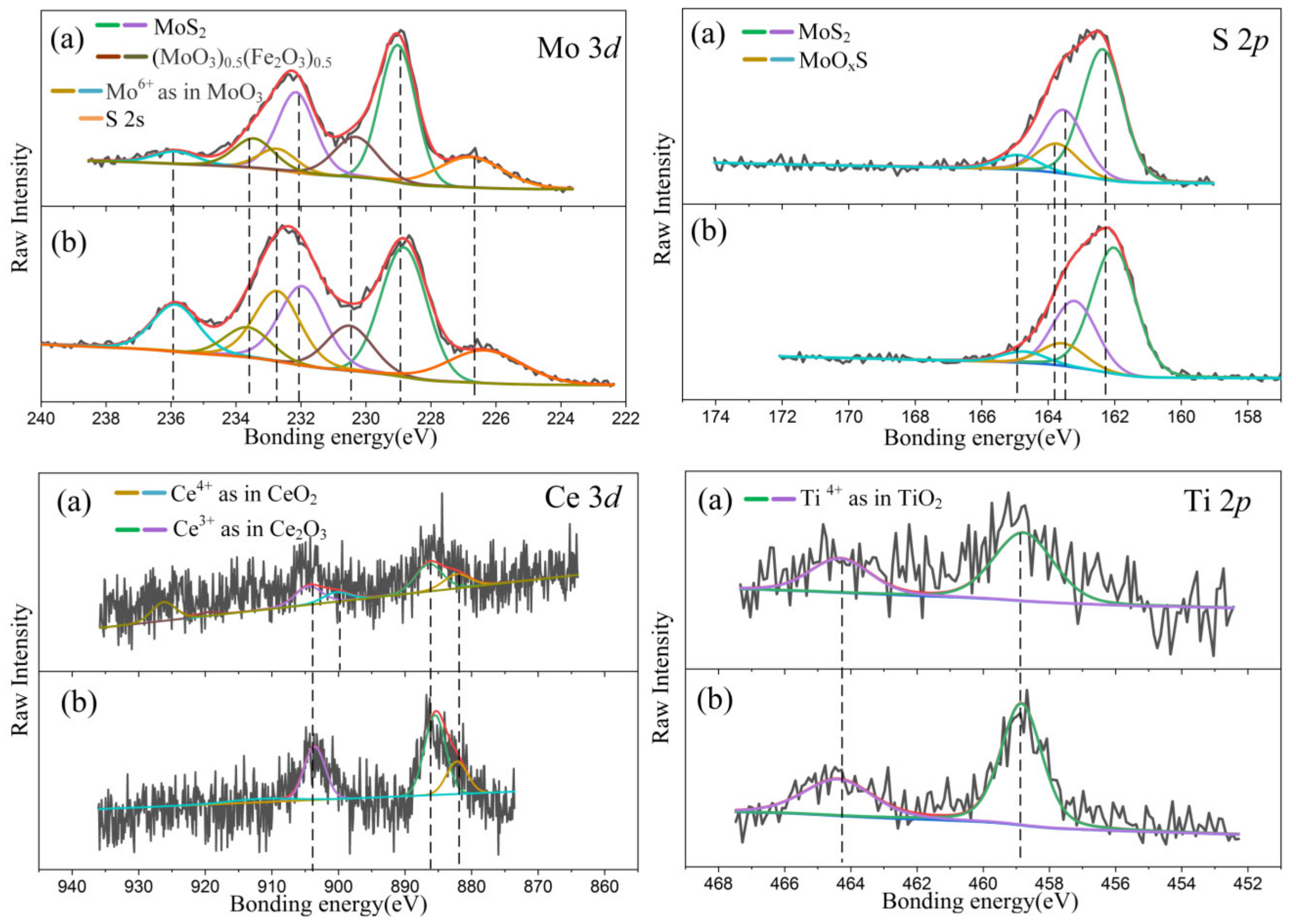
  • In the coatings composition, in addition to the main existing MoS2, MoO3 was also found to affect the tribological properties. In addition, the doping elements are in the form of TiO2, CeO2, and Ce2O3 in the coatings. The coatings at 0.6~0.9 Pa perform better oxidation resistance. With the increase of pressure, the oxidation degree of the coating is more serious, and the content of rare earth oxide CeO2 is more at 0.6 Pa, while the content of Ce2O3 is higher at 1.8 Pa.
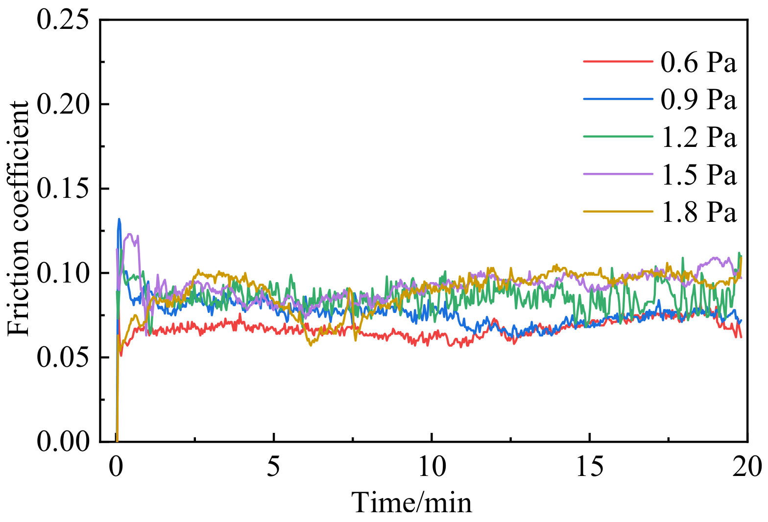
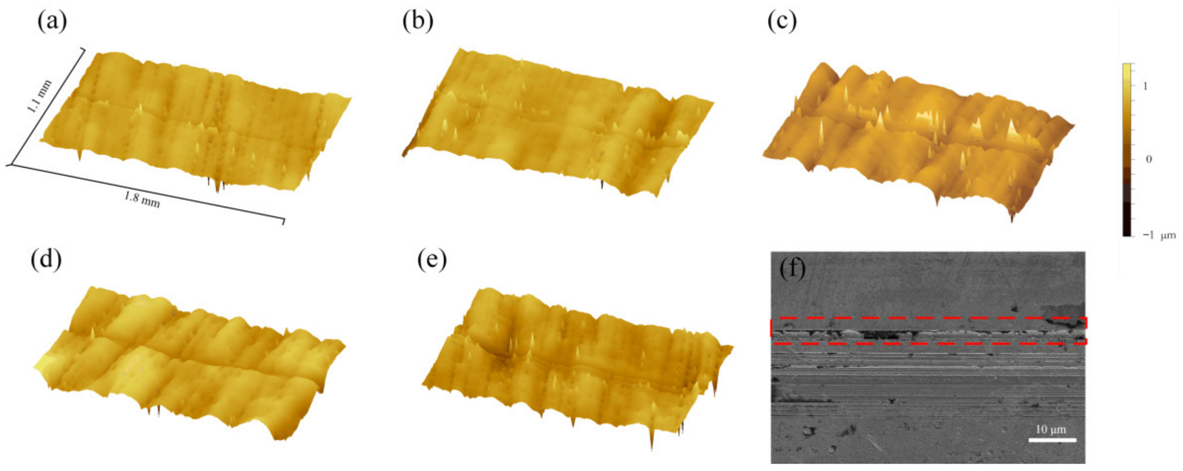
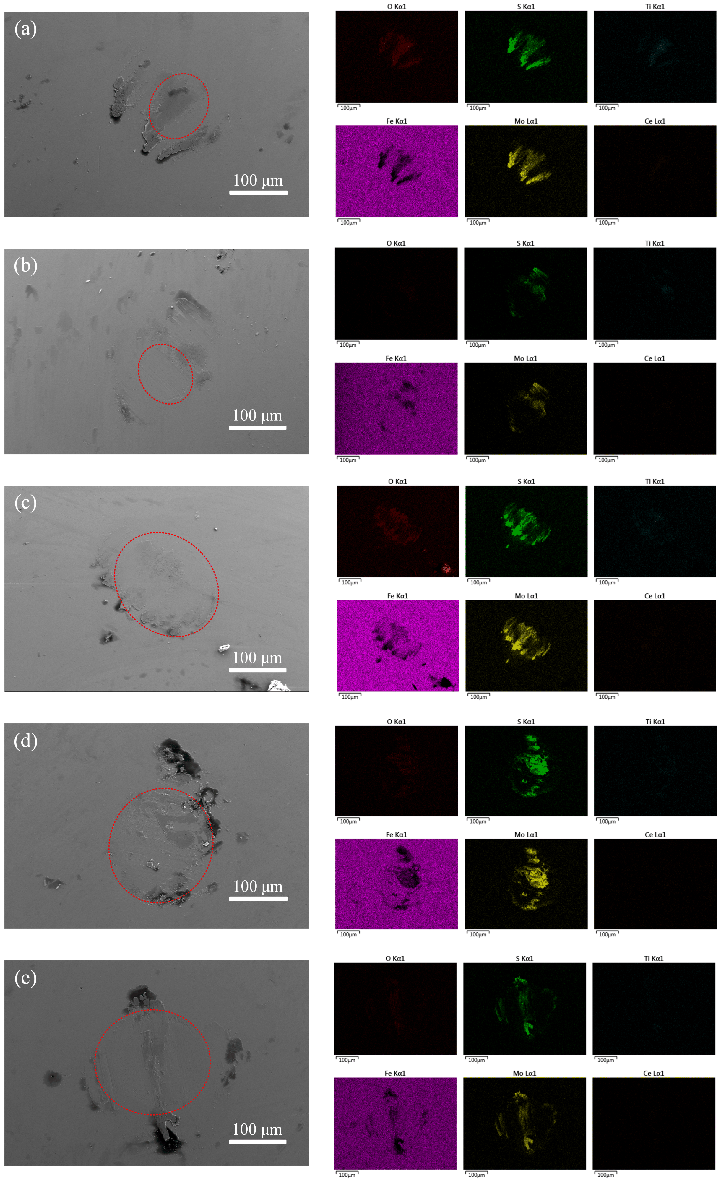
  • The coatings exhibit excellent tribological properties under low pressure: the minimum friction coefficient is about 0.065 at 0.6 Pa, and the minimum wear rate is at a pressure of 0.9 Pa. The friction coefficient and wear rate increase with the increase of pressure. The coating even produces block shedding under the friction and extrusion of steel balls at 1.8 Pa. Ce-Ti/MoS2 easily forms a transfer film on the surface of the dual steel ball during friction. The wear scar area of the coating at 0.6~0.9 Pa is the smallest. As the pressure increases, the wear scar area gradually increases, which shows that the wear scar of the coating becomes wider, and the wear rate increases. Considering the excellent wear resistance of the coating, Ce-Ti/MoS2 coating can be used in the vacuum and space fields, with applications for spacecraft motion components and rolling bearings.

Author Contributions

Conceptualization, Y.X.; Data curation, C.T.; Formal analysis, C.T.; Project administration, H.C.; Resources, Y.X.; Writing—original draft, C.T.; Writing—review & editing, H.C. and Y.X. All authors have read and agreed to the published version of the manuscript.

Funding

This research was funded by National Key Research and Development Program, Grant No. 2021YFB3400400; Project of Science and Technology Development of Henan Province, Grant No. 202102210073.

Institutional Review Board Statement

Not applicable.

Informed Consent Statement

Not applicable.

Data Availability Statement

The authors confirm that the data supporting the findings of this study are available within the article.

Conflicts of Interest

The authors declare no conflict of interest.

References

  1. Zhao, X.; Lu, Z.; Zhang, G.; Wang, L.; Xue, Q. Self-adaptive MoS2-Pb-Ti film for vacuum and humid air. Surf. Coat. Technol. 2018, 345, 152–166. [Google Scholar] [CrossRef]
  2. Rabeel, M.; Javed, S.; Khan, R.; Akram, M.A.; Rehman, S.; Kim, D.; Khan, M.F. Controlling the Wettability of ZnO Thin Films by Spray Pyrolysis for Photocatalytic Applications. Materials 2022, 15, 3364. [Google Scholar] [CrossRef] [PubMed]
  3. Sun, S.; Chen, J.; Wang, Y.; Wang, L.; Sun, Z. Structural sensitivity of MoS2-based films in solid space lubrication. Surf. Eng. 2020, 36, 106–113. [Google Scholar] [CrossRef]
  4. Hou, K.; Han, M.; Liu, X.; Wang, J.; He, Y.; Yang, S. In situ formation of spherical MoS2 nanoparticles for ultra-low friction. Nanoscale 2018, 10, 19979–19986. [Google Scholar] [CrossRef]
  5. Vazirisereshk, M.R.; Martini, A.; Strubbe, D.A.; Baykara, M.Z. Solid Lubrication with MoS2: A Review. Lubricants 2019, 7, 57. [Google Scholar] [CrossRef] [Green Version]
  6. Qian, G.; Feng, Y.; Li, B.; Huang, S.; Liu, H.; Ding, K. Effect of Electrical Current on the Tribologkal Behavior of the Cu-WS2-G Composites in Air and Vacuum. Chin. J. Mech. Eng. 2013, 26, 384–392. [Google Scholar] [CrossRef]
  7. Deepthi, B.; Srinivas, G.; Kumar, P.; Rao, D.V.S.; Barshilia, H.C. Sputter Deposited Nanostructured Au-WS2 Solid Lubricant Coatings. Nanosci. Nanotechnol. Lett. 2012, 4, 53–60. [Google Scholar] [CrossRef]
  8. Efeoglu, I.; Baran, O.; Yetim, F.; Altintas, S. Tribological characteristics of MoS2-Nb solid lubricant film in different tribo-test conditions. Surf. Coat. Technol. 2008, 203, 766–770. [Google Scholar] [CrossRef]
  9. Yang, J.; Wang, D.; Fu, Y.; Wang, Q.; Hu, M.; Jiang, D.; Gao, X.; Sun, J.; Weng, L. Improving the tribological and anti-corrosion property of the WS2 film through Ta doping. Vacuum 2021, 192, 110485. [Google Scholar] [CrossRef]
  10. Jing, Y.; Luo, H.B.; Pang, S.Q. Effect of Ti or TiN codeposition on the performance of MoS2-based composite coatings. Thin Solid Film 2004, 461, 288–293. [Google Scholar] [CrossRef]
  11. Carrera, S.; Salas, O.; Moore, J.J.; Woolverton, A.; Sutter, E. Performance of CrN/MOS2 (Ti) coatings for high wear low friction applications. Surf. Coat. Technol. 2003, 167, 25–32. [Google Scholar] [CrossRef]
  12. Zhu, L.; Cao, X.; Gong, C.; Jiang, A.; Cheng, Y.; Xiao, J. Preparation of Cu3N/MoS2 Heterojunction through Magnetron Sputtering and Investigation of Its Structure and Optical Performance. Materials 2020, 13, 1873. [Google Scholar] [CrossRef] [PubMed] [Green Version]
  13. Zinkiewicz, M.; Wozniak, T.; Kazimierczuk, T.; Kapuscinski, P.; Oreszczuk, K.; Grzeszczyk, M.; Bartos, M.; Nogajewski, K.; Watanabe, K.; Taniguchi, T.; et al. Excitonic Complexes in n-Doped WS2 Monolayer. Nano Lett. 2021, 21, 2519–2525. [Google Scholar] [CrossRef] [PubMed]
  14. Jiang, A.; Cao, X.; Wang, Z.; Ma, J.; Xiao, J.; Ma, S. Friction performance and corrosion resistance of MoS2/DLC composite films deposited by magnetron sputtering. Results Phys. 2021, 25, 104278. [Google Scholar] [CrossRef]
  15. Boskovic, C. Rare Earth Polyoxometalates. Acc. Chem. Res. 2017, 50, 2205–2214. [Google Scholar] [CrossRef]
  16. El-Bahy, Z.M.; Ismail, A.A.; Mohamed, R.M. Enhancement of titania by doping rare earth for photodegradation of organic dye (Direct Blue). J. Hazard. Mater. 2009, 166, 138–143. [Google Scholar] [CrossRef]
  17. Chesnaud, A.; Braida, M.D.; Estrade, S.; Peiro, F.; Tarancon, A.; Morata, A.; Dezanneau, G. High-temperature anion and proton conduction in RE3NbO7 (RE = La, Gd, Y, Yb, Lu) compounds. J. Eur. Ceram Soc. 2015, 35, 3051–3061. [Google Scholar] [CrossRef]
  18. Loh, L.; Chen, Y.; Wang, J.; Yin, X.; Tang, C.S.; Zhang, Q.; Watanabe, K.; Taniguchi, T.; Wee, A.T.; Bosman, M.; et al. Impurity-Induced Emission in Re-Doped WS2 Monolayers. Nano Lett. 2021, 21, 5293–5300. [Google Scholar] [CrossRef]
  19. Wang, J.; Chong, X.; Zhou, R.; Feng, J. Microstructure and thermal properties of RETaO4 (RE = Nd, Eu, Gd, Dy, Er, Yb, Lu) as promising thermal barrier coating materials. Scr. Mater. 2017, 126, 24–28. [Google Scholar] [CrossRef]
  20. Al-Hamdi, A.M.; Sillanpaa, M.; Dutta, J. Photocatalytic degradation of phenol in aqueous solution by rare earth-doped SnO2 nanoparticles. J. Mater. Sci. 2014, 49, 5151–5159. [Google Scholar] [CrossRef]
  21. Yang, Y.; Pu, H.; Di, J.; Zang, Y.; Zhang, S.; Chen, C. Synthesis and characterization of monolayer Er-doped MoS2 films by chemical vapor deposition. Scr. Mater. 2018, 152, 64–68. [Google Scholar] [CrossRef]
  22. Song, W.; Sun, K.; Zhao, G.; Zhu, L.; Wang, S.; Li, T. Performance of MoS2/Zr Composite Coatings at Different Deposition Temperatures. Materials 2021, 14, 5100. [Google Scholar] [CrossRef] [PubMed]
  23. Park, J.; Kang, Y. Effect of Radio Frequency Power on the Physicochemical Properties of MoS2 Films Obtained by rf Magnetron Sputtering. B Korean Chem. Soc. 2016, 37, 1326–1330. [Google Scholar] [CrossRef]
  24. Bulbul, F.; Efeoglu, I. Synergistic effect of bias and target currents for magnetron sputtered MoS2-Ti composite films. Mater. Test. 2016, 58, 471–474. [Google Scholar] [CrossRef]
  25. Prozhega, M.V.; Kharkov, M.M.; Reschikov, E.O.; Rykunov, G.I.; Kaziev, A.V.; Kukushkina, M.S.; Kolodko, D.V.; Stepanova, T.V. Estimation of MoS2 Coating Performance on Bronze and Steel in Vacuum at High Temperatures. Coatings 2022, 12, 125. [Google Scholar] [CrossRef]
  26. Wang, L.; Zhu, D.; Wei, Z.; Huang, L.; Song, W.; Chen, Y. The Refinement Effect of Al-Ti-C-RE Master Alloy Prepared by Adding Ce2O3 on Pure Al. Adv. Mater. Res. 2010, 139–141, 227–234. [Google Scholar]
  27. Li, Y.Z.; Shi, Y. Microhardness, wear resistance, and corrosion resistance of AlxCrFeCoNiCu high-entropy alloy coatings on aluminum by laser cladding. Opt. Laser Technol. 2021, 134, 106632. [Google Scholar] [CrossRef]
  28. Kaindl, R.; Bayer, B.C.; Resel, R.; Mueller, T.; Skakalova, V.; Habler, G.; Abart, R.; Cherevan, A.S.; Eder, D.; Blatter, M.; et al. Growth, structure and stability of sputter-deposited MoS2 thin films. Beilstein J. Nanotech. 2017, 8, 1115–1126. [Google Scholar] [CrossRef] [Green Version]
  29. Seynstahl, A.; Krauss, S.; Bitzek, E.; Meyer, B.; Merle, B.; Tremmel, S. Microstructure, Mechanical Properties and Tribological Behavior of Magnetron-Sputtered MoS2 Solid Lubricant Coatings Deposited under Industrial Conditions. Coatings 2021, 11, 455. [Google Scholar] [CrossRef]
  30. Serpini, E.; Rota, A.; Ballestrazzi, A.; Marchetto, D.; Gualtieri, E.; Valeri, S. The role of humidity and oxygen on MoS2 thin films deposited by RF PVD magnetron sputtering. Surf. Coat. Technol. 2017, 319, 345–352. [Google Scholar] [CrossRef]
  31. Zhang, C.; Yang, B.; Wang, J.; Wang, H.; Liu, G.; Zhang, B.; Liu, L.; Feng, K.; Li, Z. Microstructure and friction behavior of LaF3 doped Ti-MoS2 composite thin films deposited by unbalanced magnetron sputtering. Surf. Coat. Technol. 2019, 359, 334–341. [Google Scholar] [CrossRef]
  32. Fleischauer, P.D. Effects of Crystallite Orientation on Environmental Stability and Lubrication Properties of Sputtered MoS2 Thin Films. Asle Trans. 1984, 27, 82–88. [Google Scholar] [CrossRef]
  33. Wang, T.; Xue, C.; Yu, S.; Chen, W.; Zhang, G. The effect of S/Mo ratio on structure and properties of MoSx-Ti composite coatings deposited by magnetron sputtering. Mater. Res. Express 2020, 7, 106401. [Google Scholar] [CrossRef]
  34. Cao, M.; Zhao, L.; Wu, L.; Wang, W. Tribological Properties of New Cu-Al/MoS2 Solid Lubricant Coatings Using Magnetron Sputter Deposition. Coatings 2018, 8, 134. [Google Scholar] [CrossRef] [Green Version]
  35. Depla, D. On the effective sputter yield during magnetron sputter deposition. Nucl. Instrum. Methods Phys. Res. Sect. B 2014, 328, 65–69. [Google Scholar] [CrossRef]
  36. Xu, Y.; Xie, M.; Li, Y.; Zhang, G.; Xu, X.; Fan, X.; Sun, Q.; Li, H.; Zhu, M. The effect of Si content on the structure and tribological performance of MoS2/Si coatings. Surf. Coat. Technol. 2020, 403, 126362. [Google Scholar] [CrossRef]
  37. Chen, W.; Lin, Y.; Zheng, J.; Zhang, S.; Liu, S.; Kwon, S.C. Preparation and characterization of CrAlN/TiAlSiN nano-multilayers by cathodic vacuum arc (vol 265, pg 205, 2015). Surf. Coat. Technol. 2018, 340, 151. [Google Scholar] [CrossRef]
  38. Musil, J.; Jirout, M. Toughness of hard nanostructured ceramic thin films. Surf. Coat. Technol. 2007, 201, 5148–5152. [Google Scholar] [CrossRef]
  39. Qi, Z.B.; Sun, P.; Zhu, F.P.; Wang, Z.C.; Peng, D.L.; Wu, C.H. The inverse Hall–Petch effect in nanocrystalline ZrN coatings. Surf. Coat. Technol. 2011, 205, 3692–3697. [Google Scholar] [CrossRef]
  40. Cho, M.H.; Cho, K.H.; Kim, S.J.; Kim, D.H.; Jang, H. The Role of Transfer Layers on Friction Characteristics in the Sliding Interface between Friction Materials against Gray Iron Brake Disks. Tribol. Lett. 2005, 20, 101–108. [Google Scholar] [CrossRef]
  41. Jian, S.; Tao, L.; Shi, H.; Yan, S.; Peng, Z. Time-frequency analysis of the tribological behaviors of Ti6Al4V alloy under a dry sliding condition. J. Alloy Compd. 2017, 724, 752–762. [Google Scholar]
  42. Spalvins, T. A review of recent advances in solid film lubrication. J. Vac. Sci. Technol. 1987, 5, 212–219. [Google Scholar] [CrossRef]
  43. Zhou, H.; Zheng, J.; Wen, Q.; Wan, Z.; Sang, R. The effect of Ti content on the structural and mechanical properties of MoS2-Ti composite coatings deposited by unbalanced magnetron sputtering system. Phys. Procedia 2011, 18, 234–239. [Google Scholar]
  44. Qin, X.; Ke, P.; Wang, A.; Kim, K.H. Microstructure, mechanical and tribological behaviors of MoS2-Ti composite coatings deposited by a hybrid HIPIMS method. Surf. Coat. Technol. 2013, 228, 275–281. [Google Scholar] [CrossRef]
  45. Li, H.; Zhang, G.; Wang, L. The role of tribo-pairs in modifying the tribological behavior of the MoS2/Ti composite coating. J. Phys. D Appl. Phys. 2016, 49, 95501. [Google Scholar] [CrossRef]
  46. Han, C.; Li, G.; Ma, G.; Shi, J.; Liu, Y.; Li, Z.; Wang, H. Preparation and tribological properties of Mo/MoS2-Pb-PbS composite films. Surf. Coat. Technol. 2021, 405, 126625. [Google Scholar] [CrossRef]
  47. Seitzman, L.E.; Bolster, R.N.; Singer, I.L. X-ray diffraction of MoS2 coatings prepared by ion-beam-assisted deposition. Surf. Coat. Technol. 1992, 52, 93–98. [Google Scholar] [CrossRef]
  48. Muijsers, J.C.; Weber, T.; Vanhardeveld, R.M.; Zandbergen, H.W.; Niemantsverdriet, J.W. Sulfidation Study of Molybdenum Oxide Using MoO3/SiO2/Si(100) Model Catalysts and Mo-IV3-Sulfur Cluster Compounds. J. Catal. 1995, 157, 698–705. [Google Scholar] [CrossRef] [Green Version]
  49. Al-Shihry, S.S.; Halawy, S.A. Unsupported MoO3·Fe2O3 catalysts: Characterization and activity during 2-propanol decomposition. J. Mol. Catal. A Chem. 1996, 113, 479–487. [Google Scholar] [CrossRef]
  50. Anwar, M.; Hogarth, C.A.; Bulpett, R. An XPS study of amorphous MoO3/SiO films deposited by co-evaporation. J. Mater. Sci. 1990, 25, 1784–1788. [Google Scholar] [CrossRef]
  51. Paparazzo, E.; Ingo, G.M.; Zacchetti, N. X-ray induced reduction effects at CeO2 surfaces: An X-ray photoelectron spectroscopy study. J. Vac. Sci. Technol. A Vac. Surf. Film. 1991, 9, 1416–1420. [Google Scholar] [CrossRef]
  52. Praline, G.; Koel, B.E.; Hance, R.L.; Lee, H.I.; White, J.M. X-Ray photoelectron study of the reaction of oxygen with cerium. J. Electron. Spectrosc. Relat. Phenom. 1980, 21, 17–30. [Google Scholar] [CrossRef]
  53. Ong, J.L.; Lucas, L.C.; Raikar, G.N.; Gregory, J.C. Electrochemical corrosion analyses and characterization of surface-modified titanium. Appl. Surf. Sci. 1993, 72, 7–13. [Google Scholar] [CrossRef]
  54. Yin, B.; Kuang, X.; Xu, B.; Jia, H.; Hua, X. Experimental study on the tribological behaviour of CeO2-diesel blends on the injector body. Lubr. Sci. 2020, 32, 283–291. [Google Scholar] [CrossRef]
  55. Xie, L.; Cheng, J.; Wang, T.; Lu, X. Mechanical wear behavior between CeO2(100), CeO2(110), CeO2(111), and silicon studied through atomic force microscopy. Tribol. Int. 2021, 153, 106616. [Google Scholar] [CrossRef]
  56. Xue, Y.J.; Jia, X.Z.; Zhou, Y.W.; Ma, W.; Li, J.S. Tribological performance of Ni-CeO2 composite coatings by electrodeposition. Surf. Coat. Technol. 2006, 200, 5677–5681. [Google Scholar] [CrossRef]
  57. Sun, J.; Liu, C.; Jiang, M. Influence Mechanism of Ce2O3 on Dephosphorization Process using CaO-Al2O3-SiO2-MnO Based Slag. ISIJ Int. 2022, 62, 515–523. [Google Scholar] [CrossRef]
  58. Min, C.; He, Z.; Liu, D.; Jia, W.; Qian, J.; Jin, Y.; Li, S. Ceria/reduced Graphene Oxide Nanocomposite: Synthesis, Characterization, and Its Lubrication Application. Chemistryselect 2019, 4, 4615–4623. [Google Scholar] [CrossRef]
  59. Xu, Y.; Zhang, B.S.; Xu, B.S.; Gao, F.; Shi, P.J.; Zhang, B. Thermodynamic characteristics and tribological properties of lanthanum/serpentine composite lubricating material. Fenmo Yejin Cailiao Kexue Yu Gongcheng/Mater. Sci. Eng. Powder Metall. 2011, 16, 349–354. [Google Scholar]
  60. Du, P.; Chen, G.; Song, S.; Chen, H.; Li, J.; Shao, Y. Tribological Properties of Muscovite, CeO2 and Their Composite Particles as Lubricant Additives. Tribol. Lett. 2016, 62, 29. [Google Scholar] [CrossRef]
Figure 1. Schematic diagram of the deposition process of the Ce-Ti/MoS2 coatings.
Coatings 12 01576 g001
Figure 2. Surface FESEM micrographs of the composite coatings (a) 0.6 Pa, (b) 0.9 Pa, (c) 1.2 Pa, (d) 1.5 Pa, (e) 1.8 Pa.
Coatings 12 01576 g002
Figure 3. Cross section FESEM micrographs of the composite coatings (a) 0.6 Pa, (b) 0.9 Pa, (c) 1.2 Pa, (d) 1.5 Pa, (e) 1.8 Pa.
Coatings 12 01576 g003
Figure 4. GIXRD curves of the composite coatings deposited at different Ce-Ti deposition pressure.
Coatings 12 01576 g004
Figure 5. Hardness, elastic modulus and H/E of the composite coatings deposited at different deposition pressure.
Coatings 12 01576 g005
Figure 6. Friction coefficient curves at different deposition pressure.
Coatings 12 01576 g006
Figure 7. Three-dimensional morphology reconstruction of wear tracks (a) 0.6 Pa, (b) 0.9 Pa, (c) 1.2 Pa, (d) 1.5 Pa, (e) 1.8 Pa, (f) FESEM track graph of 1.8 Pa.
Coatings 12 01576 g007
Figure 8. Cross-section profiles of different deposition pressure (a) 0.6 Pa, (b) 0.9 Pa, (c) 1.2 Pa, (d) 1.5 Pa, (e) 1.8 Pa.
Coatings 12 01576 g008
Figure 9. Average wear rate of different deposition pressure.
Coatings 12 01576 g009
Figure 10. FESEM micrographs and EDS mapping images of the wear scars for (a) 0.6 Pa, (b) 0.9 Pa, (c) 1.2 Pa, (d) 1.5 Pa, (e) 1.8 Pa. The scratches on the surface of the steel ball are marked with red circles. The scratch area increases with the increase of deposition pressure.
Coatings 12 01576 g010
Figure 11. XPS spectra of Mo 3d, S 2p, Ce 3d and Ti 2p (a) 0.6 Pa, (b) 1.8 Pa.
Coatings 12 01576 g011
Figure 12. Wear mechanisms for Ce-Ti/MoS2 coatings sliding against 9Cr18 balls. (a) is the stage before the beginning of friction, (b) is the early stage of friction. After a certain friction time, (c) is the friction state at 0.6 Pa, (d) is the friction state at 1.8 Pa.
Coatings 12 01576 g012
Table 1. Process parameters of Ce-Ti/MoS2 coatings deposition by magnetron sputtering.
ParametersConditions
Background vacuum/Pa5 × 10−4
Deposition pressure/Pa0.6, 0.9, 1.2, 1.5,1.8
Argon flow rate/Sccm50
Deposition temperature/°C200
MoS2 Targetpower/W250
Ce-Ti Targetpower/W70
Cr Targetpower/W100
Deposition time of transitionlayer/min10
Deposition time of compositefilm/min60
Table 2. Test conditions of the friction experiments.
ParametersConditions
Loading force (N)2.4
Rotating speed(r/min)1000
Friction radius(mm)10
Time(min)20
Temperature (°C)15–20
Humidity (%, RH)50
Ball diameter (mm)6
Table 3. Chemical composition and thickness of Ce-Ti/MoS2 coatings.
Deposition Pressure (Pa)S
(at.%)
Mo
(at.%)
Ce
(at.%)
Ti
(at.%)
S/Mo RatioO
(at.%)
Thickness
(μm)
0.640.2940.522.478.580.993.141.25
0.940.3244.082.137.970.945.52.80
1.235.9142.892.327.210.8411.672.42
1.531.4041.321.314.890.7621.092.09
1.830.9941.331.285.020.7521.232.07
Publisher’s Note: MDPI stays neutral with regard to jurisdictional claims in published maps and institutional affiliations.

