Article

Change in Dimensions and Surface Roughness of 42CrMo4 Steel after Nitridation in Plasma and Gas

1
Department of Mechanical Engineering, Faculty of Military Technology, University of Defense, 662 10 Brno, Czech Republic
2
Department of Machining Technology, Institute of Manufacturing Technology, Faculty of Mechanical Engineering, Brno University of Technology, 616 69 Brno, Czech Republic
3
Department of Engineering Technologies and Materials, Faculty of Special Technology, Alexander Dubček University of Trenčín, 911 50 Trenčín, Slovakia
*
Author to whom correspondence should be addressed.
Coatings 2022, 12(10), 1481; https://doi.org/10.3390/coatings12101481
Submission received: 13 September 2022 / Revised: 29 September 2022 / Accepted: 4 October 2022 / Published: 6 October 2022
(This article belongs to the Special Issue Surface Modification of Engineering and Functional Materials)

Abstract

:
The influence of plasma nitriding and gas nitriding processes on the change of surface roughness and dimensional accuracy of 42CrMo4 steel was investigated in this paper. Both processes almost always led to changes in the surface texture. After plasma nitriding, clusters of nitride ions were formed on the surface of steel, while gas nitriding very often led to the new creation of a formation of a “plate-like” surface texture. In both cases of these processes, a compound layer in specific thickness was formed, although the parameters of the processes were chosen with the aim of suppressing it. After the optimizing of nitriding parameters during nitriding processes, it was found that there were no changes in the surface roughness evaluated using the Ra parameter. However, it turned out that when using a multi-parameter evaluation of roughness (the parameters Rz, Rsk and Rku were used), there were presented some changes in roughness due to nitriding processes, which affect the functional behavior of the components. Roughness changes were also detected by evaluating surface roughness profiles, where nitriding led to changes in peak heights and valley depths. Nitriding processes further led to changes in dimensions in the form of an increase of 0.032 mm on average. However, the magnitude of the change has some context on chemical composition of material. A larger increase in dimensions was found with gas nitriding. The change in the degree of IT accuracy is closely related to the change in dimension. For both processes, there was a change of one degree of IT accuracy compared to the ground part (from IT8 to IT9). On the basis of the achieved dimensional accuracy results, a coefficient of change in the degree of accuracy IT was created, which can be used to predict changes in the dimensional accuracy of ground surfaces after nitriding processes in degrees of accuracy IT3–IT10. In this study, a tool for predicting changes in degrees of accuracy of ground parts after nitriding processes is presented.

Graphical Abstract

1. Introduction

The assurance of the necessary quality of manufactured components is one of the key responsibilities of engineering technology. The term “quality” covers a fairly broad range, including shape and dimensional correctness, surface roughness, and changes to the material’s surface and surface layer following the completion of technological operations. Their operational reliability and service life, which combines a number of other indicators, such as service life, repairability, wear resistance, corrosion resistance, fatigue strength, and others, is a comprehensive criterion for evaluating the impact of technological operations on the quality of components.
The increasing demands for component reliability necessitate either the introduction of new materials, such as high-strength steels, to replace current ones, or the modification of existing ones’ surfaces to enhance their usable qualities. Surface modification can be accomplished in a variety of ways, including hard layer deposition [1], chemical–thermal diffusion technologies [2], or a combination of these two approaches [3,4].
Cr-Mo steel 42CrMo4 is suited for surface hardening and heat treating. This steel is frequently employed in the manufacturing of barrel and breechblock mechanisms for armaments as well as extremely stressed machine elements (shafts and connecting parts) that call for both high strength and high toughness [5]. Unfortunately, with this steel, friction causes surface degradation and shortens the useful life of the functional surfaces that come into contact. The tribological characteristics of this steel must therefore be improved for this reason.
One of the most used methods of modifying the surface properties of 42CrMo4 steel is the process of chemical-heat treatment by nitriding [6,7]. Nitriding is the surface saturation of steel by nitrogen in a gaseous or liquid state. The purpose of nitriding is the creation of a surface layer containing highly dispersed nitrides of alloy elements with a high affinity to nitrogen, which mainly include Al, Cr, Ti, W and V [8]. The condition for nitriding is that the working atmosphere in which nitriding takes place must contains nitrogen in the nascent state, which has an atomic form. The most accessible method to obtain atomic nitrogen is the decomposition of ammonia. Since decomposition takes place directly on the metal surface of nitrided steel parts at temperatures of 480–600 °C, atomic nitrogen combines with iron and the previously mentioned elements with a high affinity for nitrogen to form nitrides of the respective metals. The resulting Fe4N (so-called γ’) or Fe2-3N (so-called ε phase) has neither exceptional hardness nor special thermal stability. However, the resulting nitrides of Al, Cr, V and others are finely precipitated in the ferrite and will cause considerable hardness in steels, especially if the ferrite is present in such a fine form as in sorbite [9]. Diffusion nitriding technology leads to increasing the surface hardness, corrosion resistance, fatigue failure and tribological properties [10,11,12]. These properties can be influenced by process parameters. In Ref. [13], it is stated that the characteristics of the nitrided layer are explicitly dependent on the parameters of the nitriding process and on a material of substrate well. These are specifically the process temperature, processing time, current density and composition of the nitriding atmosphere. By controlling these parameters, we can, for example, eliminate the formation of a compound (so-called white) layer on the surface of the components [14]. The phase composition of the surface layer in the nitrided component can be derived from the isothermal section of the Fe-C-N ternary diagram for C = const. With regard to the present phases, it is divided into two basic areas [15]:
  • The pure nitride region (compound layer) is formed by nitrides, or carbonitrides of type ε (Fe2-3N) and γ’(Fe4N) of iron and alloying elements. Only exceptionally is ξ-type nitride (Fe2N) present. Its actual structure is influenced by the technology of the saturation process and the composition of the steel. A frequent phenomenon is its porosity as a result of the metastability of nitrides, the release of atomic nitrogen and the exothermic reaction during its fusion.
  • The diffusion layer is the structure of the layer consisting of ferrite and nitrides (carbonitrides) of Fe and alloying elements, possibly carbides. The formation of nitrides is essentially a precipitation process from nitrogen-saturated ferrite. The consequence of its time-dependent progress in several stages is the formation of both coherent and incoherent nitrides.
For tribological applications, it is suitable to suppress the formation of a compound layer, which is fragile and during the initial sliding contact of the friction pairs, it can separate and form hard abrasive particles, which can significantly affect wear resistance [16].
A very important aspect of the surface technology application is their influence on shape, dimensional accuracy and surface roughness. The mentioned parameters significantly affect the functional behavior of the friction pairs and thus the service life and reliability of the components. The nitriding process generally leads to a change in the dimensional accuracy and surface roughness of many materials [17]. The change in dimensional accuracy and surface roughness is caused by an increase in the volume (up to 5%) of the compound layer. This increase is mostly caused by an increase in the volume of newly formed nitride and carbonitride phases [18]. Another aspect is the presence of coherent precipitates, mainly of the FeCr(NC) type. The consequence is the distortion of the matrix lattice and the formation of local internal stresses. Due to the stabilizing effect of nitrogen on austenite, the carbon in the austenite is transformed into martensite and further transformed into the γ’-Fe4N form. However, the bcc lattice structure remains unchanged. The diffusion of nitrogen results in an increase in volume [19]. The quality of the surface is further affected by the nucleation of Fe4N1−x nitrides on the steel surface. Nitride nucleation is energetically more advantageous at the grain boundaries; however, as the incubation time increases, nitride nucleation also occurs on the outer surface of the grains, in the crystal lattice, and their further growth occurs. Small Fe16N2 precipitates in the form of dark protrusions, and long needles of Fe4N1−x are then visible on the steel surface in the cross section [20]. In particular, the surface roughness of nitrided components is affected by the formation of porosity on the surface and in the surface layer. The formation of pores is associated with the desorption of nitrogen molecules. The area with the highest nitrogen content is the surface and surface layer; therefore the highest probability of thermally activated pore nucleation is here. Pore nucleation is preferentially initiated at energetically favorable locations, such as grain boundaries in the nitrided layer. The pore formation process is described in detail in [18]. The creation of pores leads to a deterioration of roughness, both due to the presence of pores and the expulsion of grains from the surface due to the action of very high pressures in the pores, which lead to volume expansion and local grain separation [21]. The last reason for the change in dimensional accuracy and surface roughness of nitrided components is the increase in lattice parameters in the surface layer by increasing the concentration of nitrogen and the formation of dispersed iron nitrides (γ’-Fe4N) [22]. For example, the volume of the lattice increases more than two-fold.
The purpose of the research was to evaluate changes in dimensional accuracy and surface roughness of 42CrMo4 nitriding steel after gas and plasma nitriding processes. This issue is currently not adequately addressed, and it mainly concerns precise parts of weapons (barrels, breechblocks, etc.). Nitriding parameters were adjusted to suppress compound layer formation. The research was therefore focused on improving the tribological properties of the components. The importance of the research lies in the comparison of two nitriding technologies, the setting of suitable process parameters, the evaluation and interpretation of the detected changes. Based on the achieved results, the coefficient of change in the accuracy of IT components was determined, and the change in surface roughness was described.

2. Materials and Methods

Samples with dimensions of 30.3 mm × 20.3 mm × 90.3 mm were milled from a 42CrMo4 steel blank on a MAS MCV 1000 machining center (MAS, Sezimovo Ústí, Czech Republic). A total of 5 samples were produced for each nitriding technology. The chemical composition of the steel was measured by optical emission spectrometry (OES) on a Q4 Tasman spectrometer (Bruker, Billerica, MA, USA): C: 0.39, Mn: 0.72, Si: 0.31, Cr: 1.09, Ni: 0.06, Mo: 0.19, P: 0.011, S: 0.015 (wt%). The analyzed surfaces of the samples were ground on a surface grinder BPH20 NA (TOS, Hostivař, Czech Republic), with a Norton 3SG46JVS grinding wheel with dimensions of 200 mm × 20 mm × 32 mm. Spindle speed n = 2400 rpm, engagement depth h = 0.03 mm. The requirement for surface roughness was Ra = 1.6 μm. In both machining operations, semi-synthetic cutting fluid TRIM MicroSol 515 was used as a cooling medium.
The experimental samples were thermally processed, i.e., normalized and heat-treated in a LAC L70V laboratory furnace (LAC, Židlochovice, Czech Republic). The normalizing annealing was carried out at a temperature of 860 °C, for 45 min, with air cooling. Hardening was carried out at a temperature of 840 °C, while staying at the temperature for 45 min in water. This was followed by tempering at 600 °C for 100 min with water cooling. Before individual heat treatment processes, the samples were provided with a layer of Kalsen 3 protective coating against surface decarburization.
The heat treatment of the samples was followed by grinding of the functional surfaces to the final dimensions of 30 mm × 20 mm × 90 mm. The grinding parameters and the grinder used remained the same. The roughness requirements for ground surfaces were set at a value of Ra = 0.8 μm. This was achieved by finishing grinding without feed motion (sparking out).
Plasma nitriding was performed at a process temperature of 520 °C, for 14 h, in an atmosphere of 1H2:3N2, at a pressure of 500 Pa, in a Rübig PN 100/80 device (Rübig, Marchtrenk, Austria). Nitriding in gas was carried out at a temperature of 530 °C, for 7 h, at a pressure of 400 Pa, in an atmosphere of NH3/N2/H2, in a Nitrex 80/200 device (Nitrex, Montreal, QC, Canada). After nitriding, the samples were cooled to ambient temperature in the furnace. For both nitriding technologies, the parameters were set to suppress the formation of the compound layer.
A scanning electron microscope, Tescan Mira 4 (Tescan, Brno, Czech Republic), was used to analyze the surface structure of ground and nitrided samples. Metallographic analysis of cross sections of the samples was performed on an Olympus DSX500i inverted opto-digital metallographic microscope (Olympus, Šindžuku, Japan). The case depth of the formed nitrided layers was measured using microhardness curves on an automated microhardness tester AMH55 (Leco, St. Joseph, MI, USA), using a Vickers indenter and a load of 0.98 N (HV0.1). Surface hardness was measured with a Zwick ZHU 2.5 universal hardness tester (Zwick Roell Group, Ulm, Germany), with a load of 29.42 N (HV3). The evaluation of the surface roughness was carried out on a Talysurf CCI Lite coherence correlation interferometer (Taylor Hobson, Leicester, UK), at an evaluated length of 4 mm, and cut-off of 0.8 mm. A Gaussian filter was used to filter the data. The change in sample dimensions was measured on a 3D CNC coordinate machine Werth ScopeCheck®S (Werth, Giessen, Germany), 5 times on each sample. The measurement was made with a touch sensor of length l = 20 mm, with a ruby ball of diameter d = 3 mm. The results were evaluated using WinWerth®8 software. An area of 27 mm × 17 mm was measured on the fronts of the samples, and 25 measurement points were taken from this area. The measurement took place at a constant temperature of 22 ± 1 °C and a relative humidity of 55%. The maximum measurement error for the sample length l = 90 mm was 3.25 μm, the measurement uncertainty for the sample length l = 90 mm was ± 0.001 mm.
To determine the dependence of the change in dimensional accuracy and surface roughness after nitriding processes, their mutual relationship was evaluated. The relationship between dimensional tolerance and surface roughness was discussed, for example, in work [23]. An overview of the recommended surface roughness depending on the degree of accuracy and size is given in [24]. It is recommended to determine the surface roughness value from the relationship:
R z = K × T ,
where K is a coefficient including the effects of various factors, and T is the dimension tolerance.
The interrelationship between surface roughness and dimensional tolerance can be expressed by the maximum clearance:
T =   D m a x       D m i n ,
T 2 = T 1 2 + R t ,
T = T 1 + 2 R t ,
Surface roughness and dimension tolerance and their mutual relationship according to the type of storage of the components is shown in Figure 1.
If chosen,
2 R t = T 1 3 ,
T 1 = 6 × R t ,
T 2 = 6 × R t 2 + R t = 4 × R t R t   1 8 × T ,
The surface roughness therefore depends on the tolerance. The value c = 1 8 × T was determined for bearing with clearance (moveable):
R t = ( 0.11 ÷ 0.20 ) × T ,
If the frictional surfaces of the functional components are considered, then as the wear progresses, the bearing area of the profile increases. The rate of wear is inversely proportional to the size of the bearing surface for the same surface load. The bearing area is given by
R = f ( z ) ,
The rate of wear is determined by
v 0 = c × 1 f ( z ) ,
where c is a constant.
At the beginning, the rate of wear v0 is high, then it decreases and takes on a linear course. The time t during which the roughness wears down to the Rt value can be expressed by the equations
R t = d z d t d t = d z R t ,
d t = f ( z ) c d z ,
t = 1 c × 0 R t f ( z ) d z ,
During the time tmax, the entire roughness Rt will wear out. One can also encounter the term wear half-time tmax/2, after which the surface roughness generally drops from the Rt value to the Rt1/2 value. However, this value is influenced by the shape of the roughness profile. The roughness of the surface must be such that during operational wear of the surfaces, the difference in the largest clearances of adjacent bearing types is completely or partially suppressed. The criterion is such a value of wear when the clearance difference increases to 1/2. If it were the case that the unevenness of the surface would wear out completely (for a time tmax), the clearance of the neighboring bearing types would increase by the value
v = 2 × R t h o l e + 2 × R t s h a f t ,
During tmax/2 (wear half-life),
v 1 / 2 = v × k = Δ v 2 ÷ 3 ,
where Δv is the clearance, and k is the coefficient indicating the dependence of wear on time, which is determined according to the relationship
k = v 1 / 2 v m a x ,
The surface roughness may, therefore, be maximal such that the wear value is less than 1/2 to 1/3 of the bearing play difference. The values of the coefficient k, indicating the dependence of wear on time, range from 0.4 to 0.7 [25].
In the case of some steels, the nitriding process causes significant changes in the dimensional accuracy and surface roughness [26], and these changes then affect the dimensional tolerances of the part and have an effect on their functional properties and service life.

3. Results

The prepared samples were metallographically analyzed after the application of nitriding, mainly for the purpose of measuring the thickness of the compound layer. Furthermore, the surface hardness and the depth of the diffusion layers were measured using the microhardness curves so that it was possible to compare the changes in the mechanical properties of the two selected nitriding processes. In terms of demonstrating surface texture changes (roughness) and dimensional changes (tolerance), the experimental activities listed below were carried out.

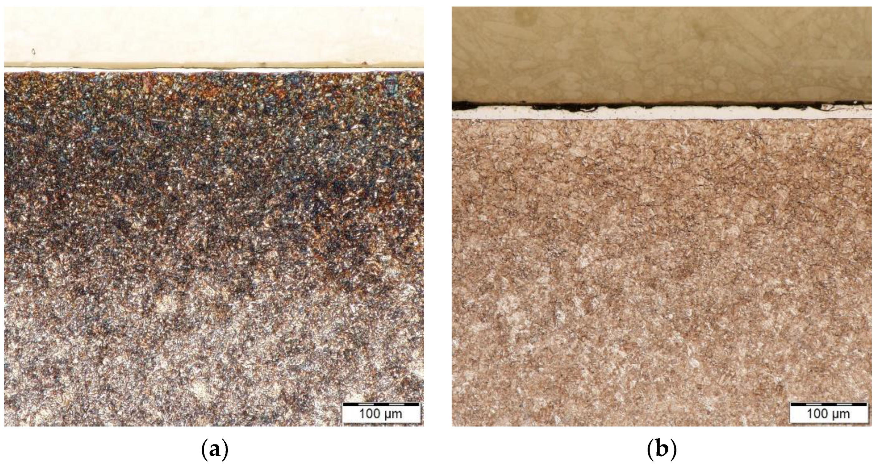
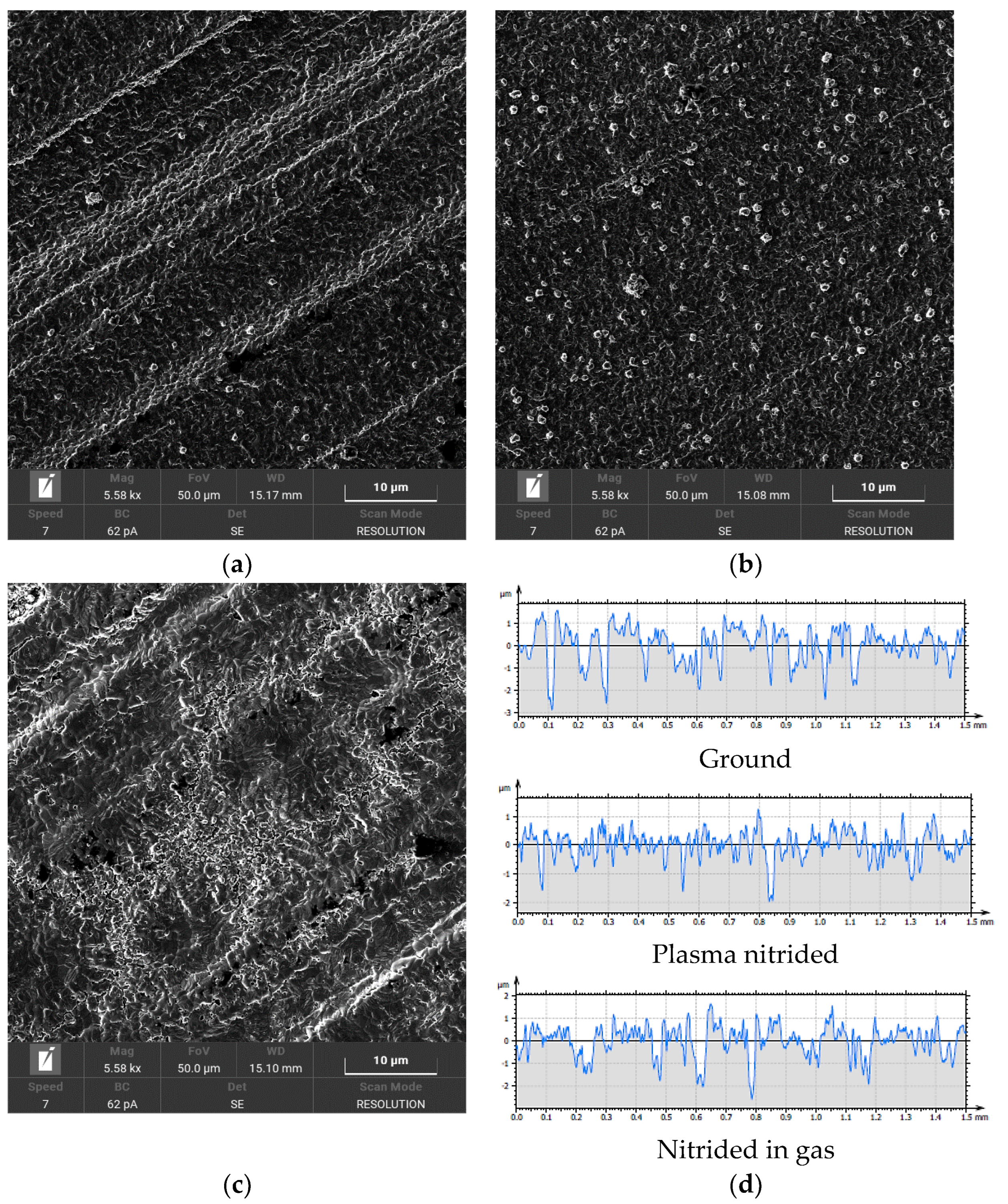
3.1. Metallographic Analysis

Micrographs of the cross-section of the nitrided layers after plasma nitriding and gas nitriding, taken with an opto-digital microscope, are shown in Figure 2. Cross sections were provided due to their fundamental description and subsequent evaluation of the thickness of the compound layer.
The steel structures after both nitriding processes consist of sorbite and tempered martensite. The thickness of the compound layer created by plasma nitriding was 6.4 ± 1.1 μm, while in gas nitriding, the thickness of the compound layer reached a value of 18.4 ± 0.5 μm. In both processes, the nitriding parameters were chosen so that the formation of the compound layer was suppressed. Various required structures of the surface layer, such as ε, ε + γ, γ′, γ′ + α or α, are regulated by changing the voltage, pressure and composition of the atmosphere. The nitriding parameters, especially the nitriding potential, then depend on whether a single-phase layer consisting of only γ′-nitride is formed. If the nitriding potential in the gaseous atmosphere is high enough before a closed γ′-nitride layer is formed, additional ε-nitrides of iron ε (Fe2-3N) are formed on the γ′-nitrides. The lateral growth of these twins eventually leads to the formation of a two-phase layer consisting of γ′- and ε-nitrides of iron in the binary iron–nitrogen system. If the base material is alloy steel, the γ′- and ε-nitrides typically appear mixed, often with the γ′-grains embedded in a continuous ε-phase. Additional alloying elements can lead to the formation of additional nitrides depending on their Gibbs energy [27,28]. The large difference in the thickness of the compound layer after the gas nitriding process can be explained by the fact that adding nitrogen to ammonia can create a higher concentration gradient of nitrogen on the steel surface, which can promote the diffusion rate and thereby increase the thickness of the compound layer and the diffusion zone. The nitrogen content in the gas mixture therefore has an obvious effect on the formation of the compound layer, which was also confirmed in the paper [29]. In Ref. [30], it is stated that the higher surface concentration of nitrogen, which occurs in gas nitriding, is favorable for the formation of ε (Fe2-3N) nitrides.

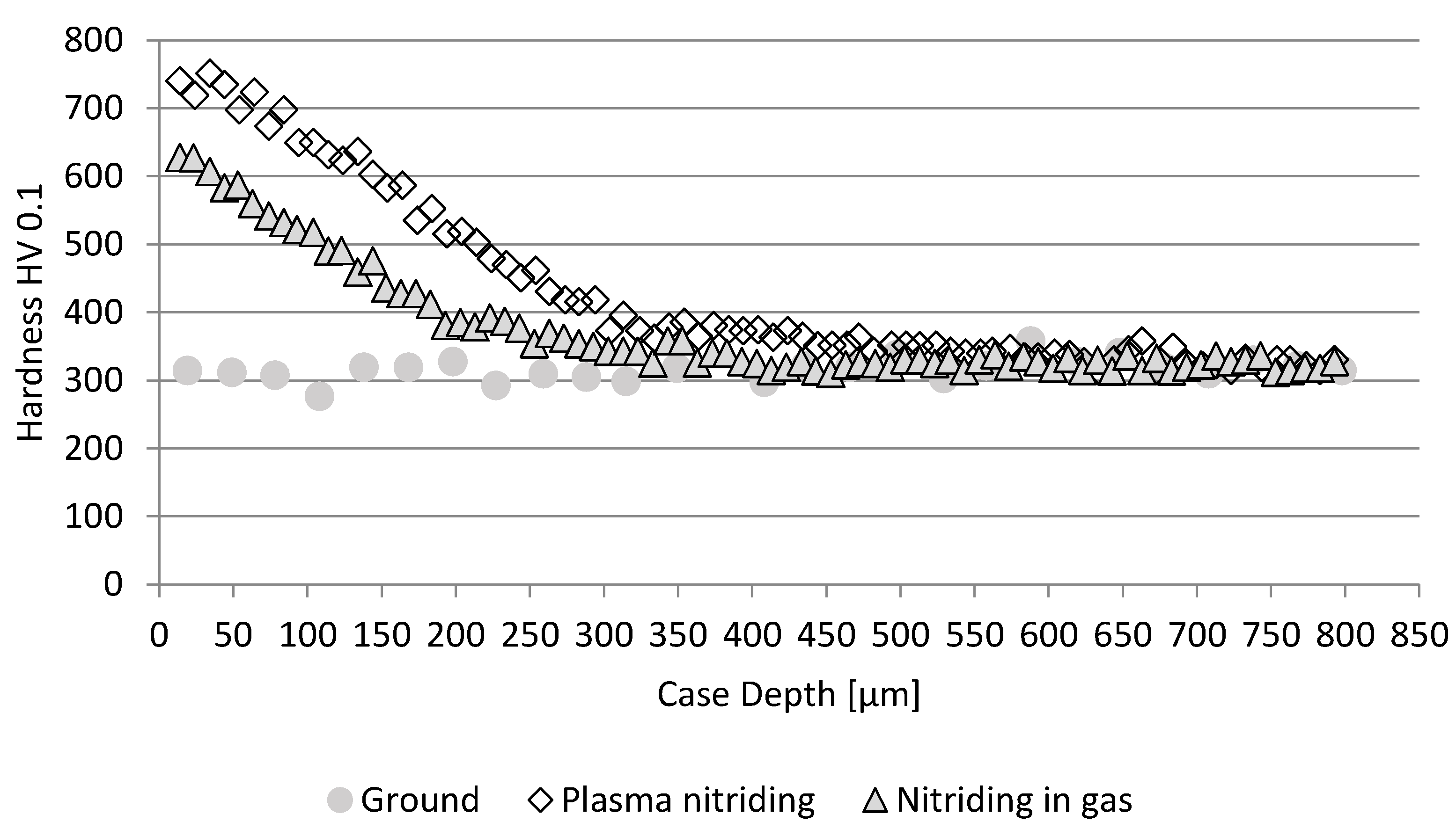
3.2. Measurement of Surface Hardness

By measuring the hardness of the surface with a load of 3 kg (29.42 N), the hardness of both the compound layer and the diffusion layer, which takes over the function of the base under this load, was evaluated. Therefore, the hardness of the surface of the compound layer + diffusion layer system is measured. The ground surface of the heat-treated samples reached a surface hardness of 278.26 ± 12.45 HV3. The plasma nitriding process led to an increase in surface hardness to 709.16 ± 11.92 HV3. Surface hardness after gas nitriding reached 693.80 ± 33.51 HV3. A comparison of both nitriding processes shows that plasma nitriding led to higher hardness values compared to gas nitriding; however, it is evident that the increase is not significant.

3.3. Evaluation of the Depth of the Diffusion Layer

The profiles of the plasma and gas nitrided 42CrMo4 steel samples are shown in Figure 3. It can be observed that the microhardness of the surface and the depth of the diffusion layer increased with the nitriding time. The depth of the diffusion layer (NHD) is dependent on the duration of the process according to the relationship given in [31]:
N H D = K t ,
where t is the time of the process in hours and K is the temperature factor given, for example, in Ref. [32].
The surface hardness of the samples after plasma nitriding was 753 ± 11 HV0.1, with a diffusion layer depth of 0.319 ± 0.009 μm. The samples after nitriding in gas reached a surface hardness of 637 ± 8 HV0.1 and a diffusion layer depth of 0.224 ± 0.026 μm. One of the reasons for the higher hardness of the nitrided surface after plasma nitriding is again the longer process time, during which the surface is more intensively saturated with nitrogen and the compound layer containing the phase γ′(Fe4N) + ε (Fe2-3N) is formed and the diffusion layer is strengthened. As the ε/γ′ ratio increases, the surface hardness increases [33,34]. The degree of supersaturation of the surface adsorption layer is exponentially related to temperature and depends on the time of the process and the saturation potential of the environment. As the process time increases, the hardness of the surface part of the diffusion layer increases. Likewise, a longer process time leads to an increase in its depth.

3.4. Surface Texture Analysis

The diffusion processes changed the morphology and texture of the surface. Figure 4 shows an SEM image of the surface of 42CrMo4 steel after heat treatment and grinding to the required roughness Ra = 0.8 μm and after nitriding in plasma and in gas. The image of the ground surface (Figure 4a) shows traces of the grinding tool, in the form of a directed structure (peaks and valleys). The structure of the ground surface is determined by the size of the grinding grains, their shape and the distance between them as well as the cutting speed of the wheel, the speed of the workpiece, longitudinal displacement and sparking out. The grinding wheel dressing conditions also have their influence. The dimensions of the grinding grains are determined by the grit, where it is true that a smaller grain size (smaller grit) is chosen when less surface roughness is required. The shape of the grains is determined by the type of abrasive used. The distance between the grains is determined by the structure of the wheel (its porosity), which is chosen according to the material being machined, the shape of the workpiece, the grinding method, the size of the contact area between the wheel and the workpiece, the amount of material removed, and the type of grinder. It is generally known that the resulting surface roughness depends on the mean thickness of the chip removed by the abrasive grain. It is true that the smaller the mean thickness of the chip, the smaller the surface roughness, quantified, e.g., by the Ra value, must be. By reducing the cutting speed of the grinding wheel and increasing the transverse feed speed, the surface roughness increases. The effect of sparking out softens the profile of the ground surface. The method of dressing the wheel has a direct effect on the surface roughness; in the case of bad dressing, a periodic component of the surface profile can be created, and the surface roughness can increase.
The steel surface after plasma nitriding is shown in Figure 4b. Compared to the ground surface, the nitrided surface shows a rugged morphology and contented texture with clusters of spherical particles (nitride ion clusters) in the range of 0.5–1 μm. The occurrence of these particles is regular and forms a compact, continuous layer. Plasma nitriding resulted in a change in the surface texture and thus the suppression of the original structure after the grinding tool. Clusters of ions on the surface are created as a result of the nitriding process in the plasma and are presented, for example, in [35]. It is also stated here that the chemical composition of the steel has no significant effect on the surface texture after plasma nitriding. This is closely related to the process parameters, especially temperature, nitriding time or micropulse parameters. Clusters of ions create partial porosity within the surface part [36], which can be a negative parameter with regard to corrosion resistance. In work [37], it is stated that the concentration of elements in nitrided steel 42CrMo4 was 80% Fe, 11% C and 4% N at the same parameters of the nitriding process.
The gas nitriding process (Figure 4c) resulted in a highly fragmented surface with a large number of plate-like particles, which are caused by the presence of different substances. Traces of the grinding tool in the form of dominant peaks are visible on the surface texture. In the central part of the image, the newly created surface creates valleys in the form of craters. Compared to the surface of the sample after the plasma nitriding process, the sample after gas nitriding has a rougher surface texture and it is visible as a presented rougher morphology. As part of the created surface structure, the nitride phases of the alloying elements were formed, and the surface compound layer was formed. On this surface, the presence of pores can be identified; the principle of their formation during nitriding was presented, for example, in Ref. [38]. As a result of nitriding in gas, there is very often a more significant development of porosity related to the subsequent brittleness of the surface layers in gaseous environments.
Surface roughness profiles (evaluated length 1.5 mm) are shown in Figure 4d. The profiles show changes between the ground surface and the surfaces after nitriding processes. A more detailed analysis of surface roughness profiles is given in Section 3.5.

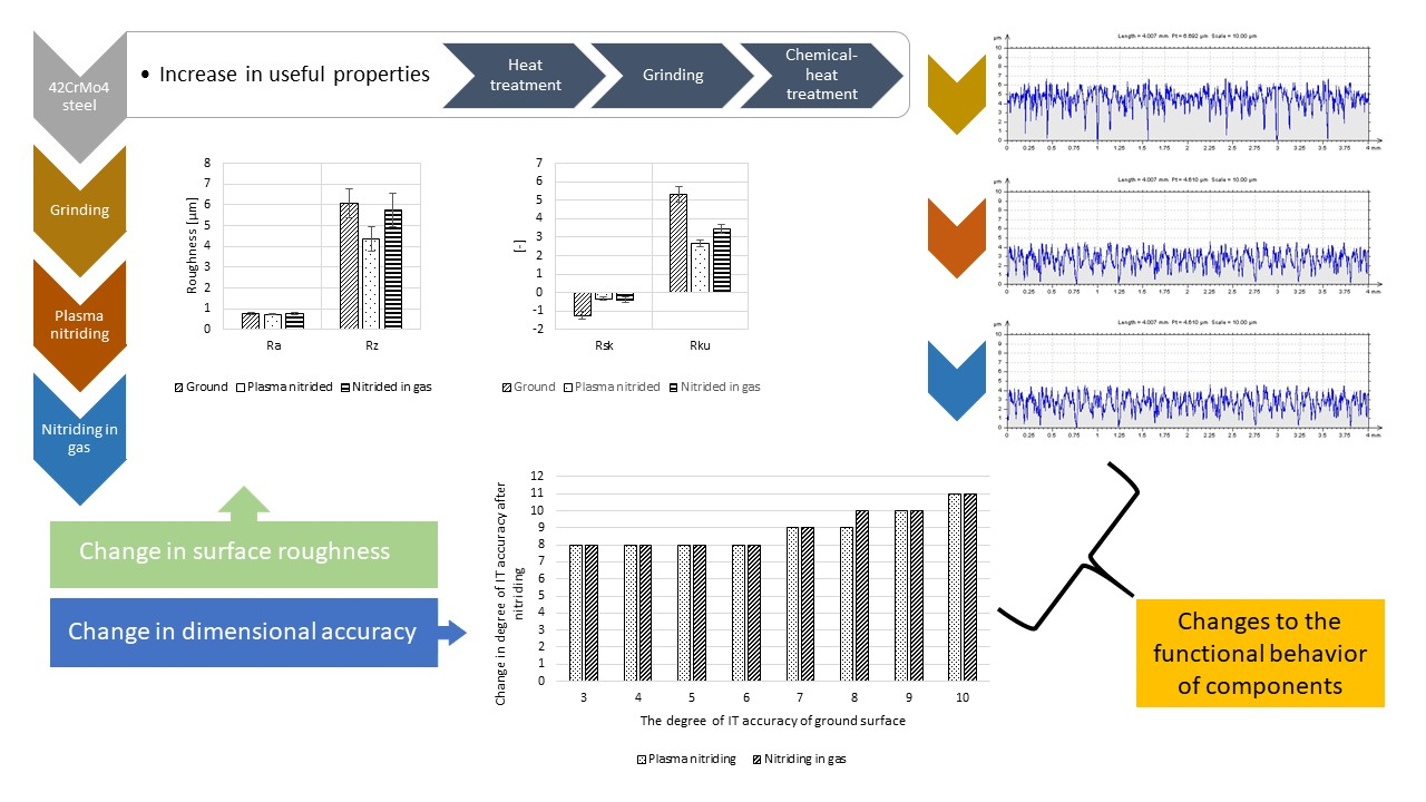
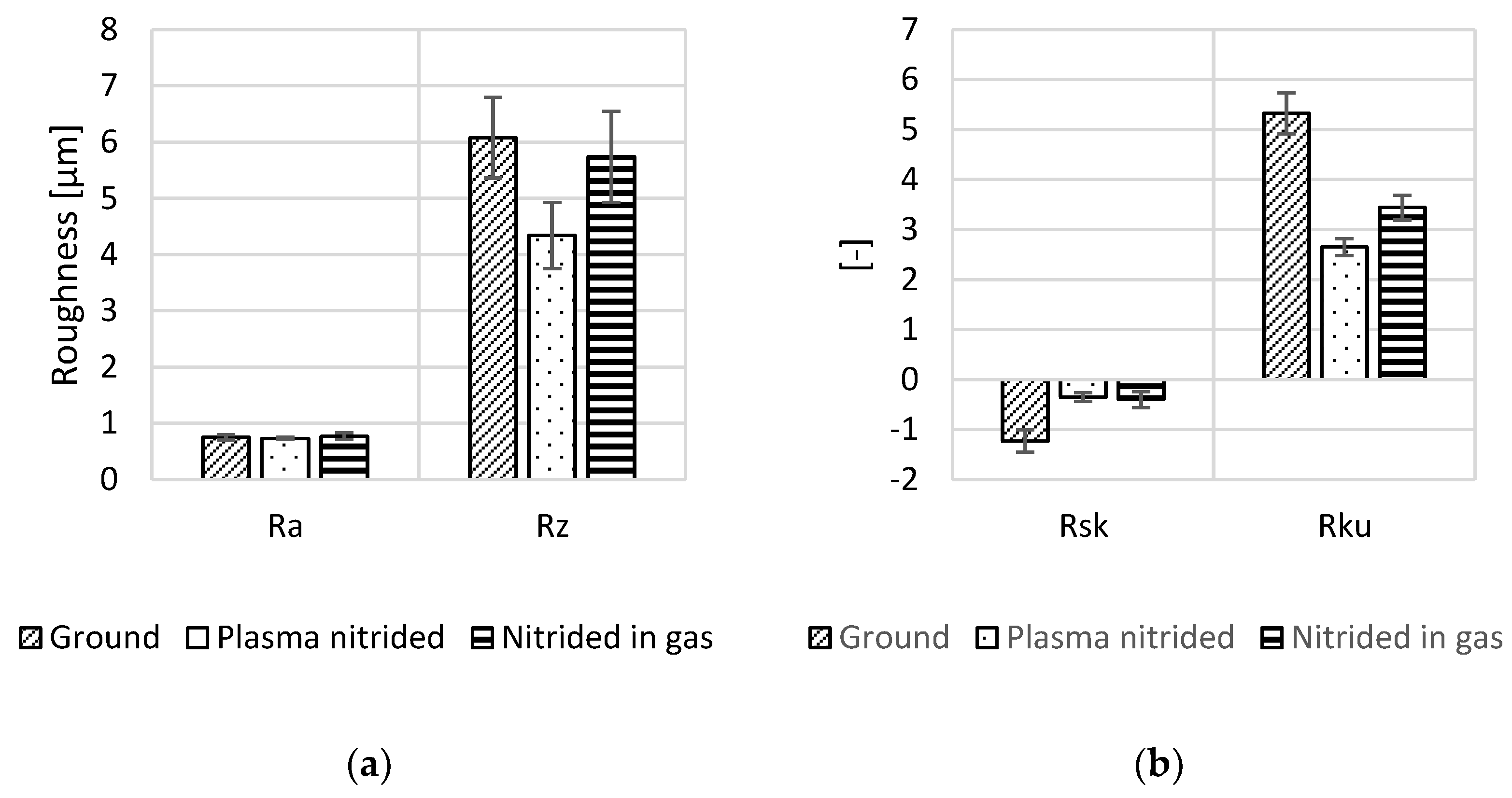
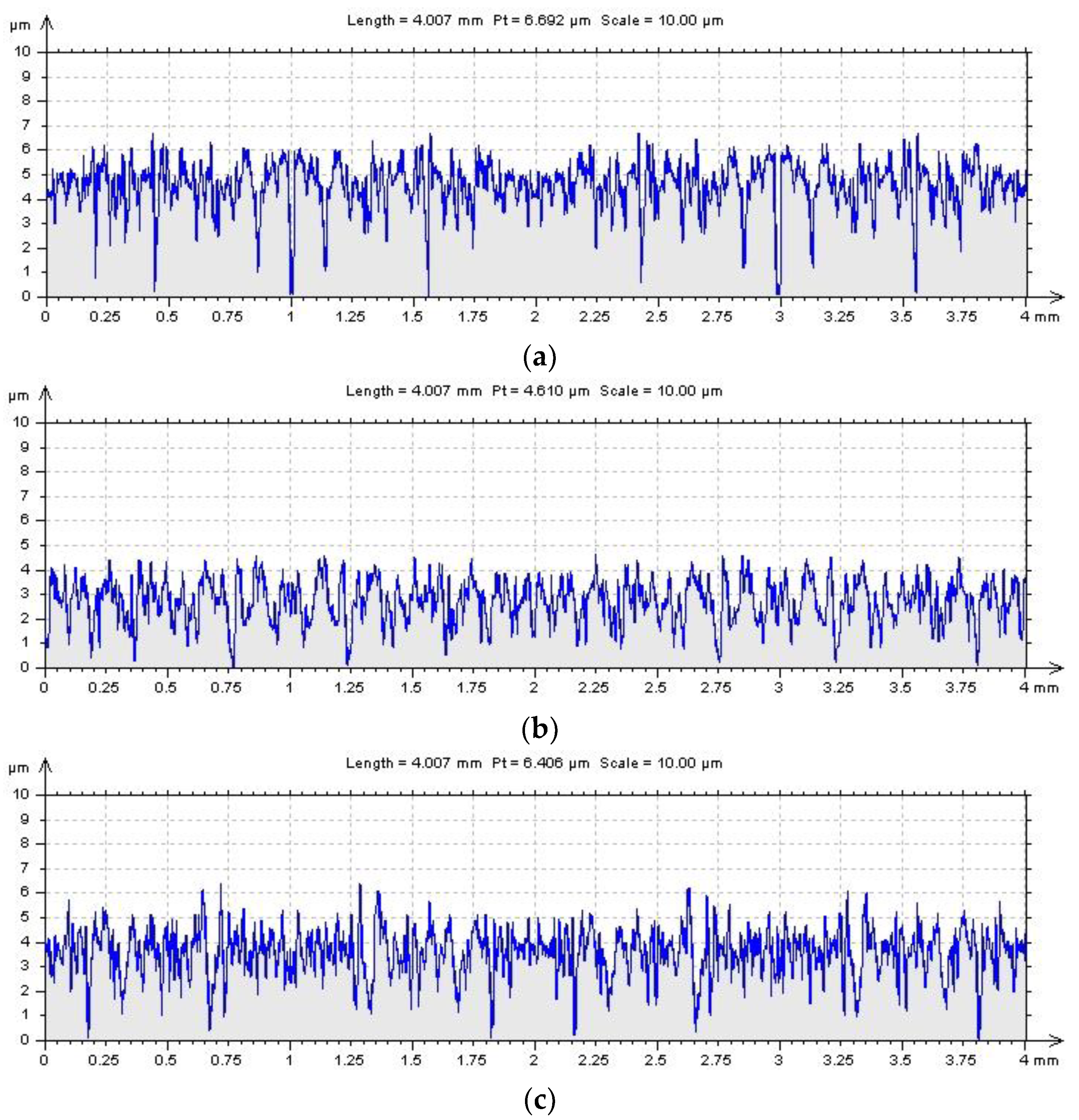
3.5. Assessment of Surface Roughness

The 2D height roughness parameters Ra, Rsk, Rku and Rz were selected for the assessment of surface roughness changes. The names and units of the parameters are given in Table 1 and are based on the EN ISO 21920-2 standard.
Figure 5 shows the results of measuring the 2D height parameters of the roughness profile. From the results of the Ra parameter (Figure 5a), it is evident that none of the nitriding processes led to a deterioration of the surface roughness. The ground surface reached Ra = 0.75 ± 0.05 μm, the surface after plasma nitriding Ra = 0.73 ± 0.02 μm, and gas nitriding led to Ra = 0.77 ± 0.06 μm. From the evaluation of the roughness results with the Ra parameter, it is clear that the nitriding processes did not lead to a change in the roughness of the ground samples. The Ra parameter is the most widely used parameter in engineering. It is considered a control parameter that is used to identify process changes. Because it has an averaging character, its results are more stable. For fine surfaces, it is not as sensitive to random surface defects, which are, however, important from the point of view of function. However, its disadvantage is that it cannot accurately describe the microgeometry of the surface. Surfaces with different profile shapes can then have the same Ra value, although their behavior in function will be completely different.
The parameter Rz determines the sum of the height of the highest peak and the depth of the deepest valley of the roughness profile on the sampling length. Since this parameter is averaged over several basis lengths, it is slightly more stable than Ra. For contact surfaces, a higher Rz value indicates a greater probability of the profile being penetrated by an oil film. From the results shown in Figure 5a, it is clear that the values of this parameter changed during nitriding processes. Compared to the ground surface (Rz = 6.08 ± 0.72 μm), after plasma nitriding, this parameter decreased to the value of Rz = 4.34 ± 0.59 μm. A decrease was also recorded in the case of nitriding in gas, to the value of Rz = 5.74 ± 0.81 μm. It is clear from Figure 6b that plasma nitriding reduced the depth of the depressions on the surface profile, compared to the ground surface. The same phenomenon occurred after gas nitriding, although here, the reduction in the depth of the depressions is not as significant. From the point of view of microgeometry, all roughness profiles are similar; they are non-periodic profiles characteristic of surfaces after a grinding operation.
Numerical values of the skewness Rsk indicate either how the probability density function shifts, relative to a Gaussian normal distribution, toward peaks (Rsk < 0) or valleys (Rsk > 0). This means that if depressions predominate on the evaluated surface, the Rsk parameter is negative; in the case of a predominance of protrusions, the Rsk parameter is positive [39]. If the value of the skewness Rsk is zero, the peaks and valleys are in balance. From the results of the parameter Rsk in Figure 5b, an increase in its value after nitriding processes is visible. The ground surface reached the value Rsk = −1.23 ± 0.22. The plasma nitriding process reached the value Rsk = −0.35 ± 0.09 and gas nitriding Rsk = −0.40 ± 0.16. Thus, nitriding processes led to a decrease in the depth of the valleys and a shift of the profile elements to the peaks. In general, a negative slope indicates good wettability (lubrication abilities), adhesion properties and suitability of the surface as a bearing surface. Nitriding processes deteriorate these surface properties.
Kurtosis Rku is often used to monitor the wear of friction pair surfaces [40]. Even in the case of this parameter, one can notice different results for nitrided surfaces compared to the ground surface (Figure 5b). If there are a large number of deep valleys and peaks on the surface, the kurtosis Rku > 3; this is the case of a ground surface (Rku = 5.33 ± 0.41). In the opposite case, Rku < 3, which occurred after plasma nitriding (Rku = 2.65 ± 0.17), so there was a reduction in the number of peaks and valleys. The normal distribution of peaks and valleys (Gaussian normal distribution) therefore corresponds to the kurtosis Rku = 3. This case can be considered after the nitriding process in gas (Rku = 3.44 ± 0.25). It is therefore clear that the nitriding processes led to changes in the microgeometry of the surface that was obtained by the grinding operation.
From the above, it follows that the minimal changes in the surface roughness of the samples after nitriding, which were compared with the ground surface and expressed by the Ra parameter, contain significant changes that affect the tribological behavior of the functional surfaces. These changes are expressed using a multiparametric evaluation of the monitored surfaces. This method of evaluation is currently very often used, as shown, for example, in [41,42,43,44]. In addition, the inappropriateness of evaluating the surface roughness by the Ra parameter alone is confirmed.

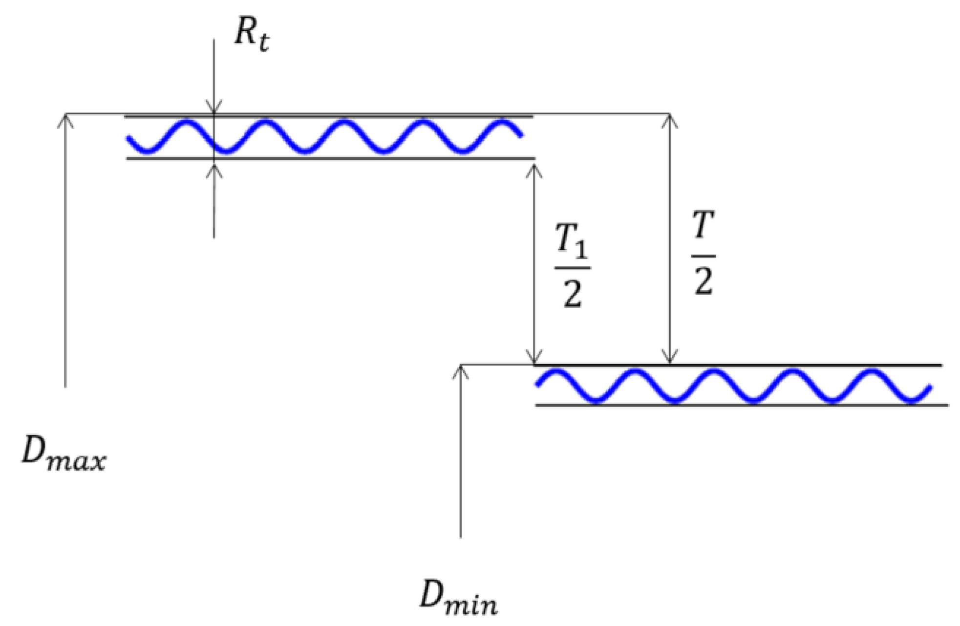
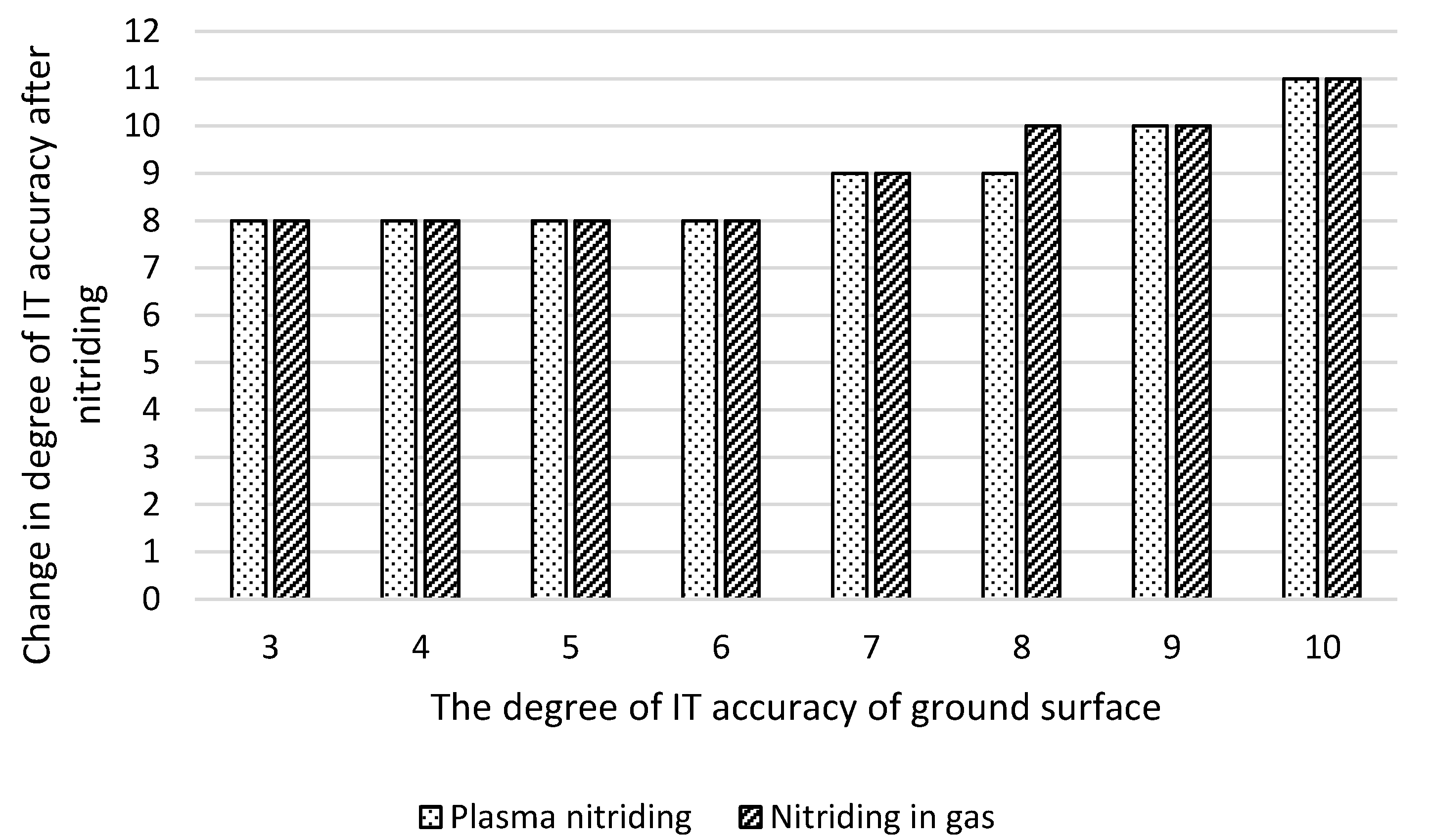
3.6. Dimensional Change after Nitriding

The changes in the dimensions of the samples after the evaluated nitriding processes are shown in Table 2. The values of changes in the dimensions of the samples express the mean value of the change in dimensions from 25 measurements of 5 samples of each nitriding process. Dimensional changes are compared with the mean value of the same series of heat-treated ground samples, which here represents the reference value 0, respectively. The required nominal dimension of the sample l = 90 mm.
It is clear from the results that both nitriding processes led to an increase in the dimensions of the samples, by 0.03 mm in the case of nitriding in plasma and by almost 0.04 mm in the case of nitriding in gas. Changes in sample dimensions after nitriding processes affect their dimensional tolerances. Table 3 shows the dimensional tolerances of the measured samples, represented by the lowest and highest mean value measured in a given series of samples, for a nominal dimension of l = 90 mm. Table 3 further lists the degrees of accuracy achieved for the evaluated nitriding processes, which are compared with the degree of accuracy of refined ground samples (in accordance with the EN ISO 286-1 standard). Both nitriding processes led to changes in the tolerance of the samples and to an increase in the degree of accuracy of IT by one degree.
The achieved changes in degrees of IT precision can be better illustrated after the nitriding processes by means of their increase, which is shown for individual degrees of precision of ground surfaces in Figure 7. Based on the obtained results, the changes in degrees of accuracy were recalculated for ground surfaces produced in degrees of accuracy IT3 to IT10, to which the process of nitriding in plasma and gas is applied. It can be seen from the results that both nitriding processes lead to a change in the degree of accuracy to IT8 for transfer grades IT3–IT6, which is a deterioration of 5 to 2 degrees of IT accuracy. If the functional surfaces are ground to the IT7–IT10 degree of accuracy, there is an increase of one degree of IT accuracy, except for gas nitriding at the accuracy degree of IT8, where an increase of two IT degrees of accuracy was noted. Nitriding processes for ground parts, produced in higher degrees of IT accuracy, therefore lead to a deterioration of 1 to 2 degrees of IT accuracy.
From the achieved results, the following relationship was derived for the change in the degree of IT accuracy after nitriding processes:
I T N i t = I T G × k z I T ,
where ITNit is the degree of IT accuracy achieved after the nitriding process, ITG is the degree of IT accuracy of the ground part, and kzIT is the coefficient of change of the degree of accuracy after nitriding. The mean values of the coefficient kzIT for steel 42CrMo4 and for individual degrees of ground surfaces are given in Table 4.
The determined mean values of the coefficient of change of the degree of accuracy IT kzIT are defined for the nominal dimensions of the component l = 90 mm. They can also be used for nominal dimensions of components in the range l = 80 mm to l = 100 mm. For steel 42CrMo4, the values of this coefficient were also successfully used for components with dimensions l = 32.5 mm, where the change in size and surface roughness after plasma nitriding was solved [45].

4. Discussion

Nitriding processes, provided on both samples, caused the changing of parameters of surface structure, especially hardness, texture and morphology.
Samples of 42CrMo4 steel were nitrided in plasma and in gas, with the aim of evaluating the effect of these processes on surface roughness and dimensional accuracy. The nitriding parameters were chosen in accordance with the results in the work [46,47,48] with the aim of suppressing the formation of a compound layer, which has a negative effect on the tribological properties of sliding pairs, as stated, for example, in [49,50,51,52]. Some studies report a detrimental effect on the tribological properties of surfaces with a compound layer thicker than ~5 μm [53,54]. After the nitriding processes, a compound layer with a thickness of 6.4 ± 1.1 μm after plasma nitriding and 18.4 ± 0.5 μm after gas nitriding was obtained, which, especially in the case of gas nitriding, significantly exceeds the recommended values for use in tribological applications.
When evaluating the texture of the steel surface after the selected nitriding processes, changes were detected in the form of the creation of a more fragmented morphology. On the surface of the steel, after plasma nitriding, a fragmented texture with clusters of spherical particles (clusters of nitride ions) with a diameter of 0.5 to 1 μm was formed. Similar changes in the surface texture were also achieved during the nitriding of AISI 316L steel in work [55], where the spherical particles are called oxynitrides (due to the composition of Fe, N and C). The process of nitriding in gas led to the formation of a very broken surface with a large number of plate-like particles. In work [56], it is stated that nitriding in gas leads to the coarsening of grains and the revelation of their boundaries, which corresponds precisely to the creation of a “plate-like structure” of the surface. Different nitriding processes lead to different changes in surface texture [57,58].
The main cause of the change in the surface roughness and dimensional accuracy of components after nitriding is primarily the phase transformation of austenite to martensite, which causes an increase in their volume [59] and subsequent distortion of the crystal lattice. In the case of nitriding processes, another factor is the diffusion of nitrogen into the steel surface, which leads to an increase in the volume of the compound layer. In work [60], it is stated that the change in the dimension of the component is proportional to the thickness of the compound layer. For example, in C45 and 16MnCr5 steels, the dimensional increase was found to be 30% to 50% of the compound layer thickness. However, in the case of 42CrMo4 steel, the increase in size was more than 500% of the thickness of the compound layer in plasma nitriding and almost 200% in gas nitriding. The reason may be the deformation of the matrix lattice, which is caused by the oversaturation of ferrite with nitrogen and thus causes the emergence of macroscopic stresses in the diffusion layer [61]. In work [62], it is stated that supersaturation of ferrite with nitrogen can reach a value of up to 300% of the equilibrium concentration of nitrogen. The precipitation of nitrides induces long-range stress fields, especially in the vicinity of coherent precipitates. In the event that the precipitation processes proceed until the formation of stable precipitates of the γ´-Fe4N type, the result is a significant reduction in stress; however, their formation is accompanied by an increase in volume and the emergence of macroscopic compressive stresses [63,64].
The surface roughness values, expressed by the Ra parameter, did not change after the nitriding processes (Ra~0.75 μm). Even though this parameter is the most used in engineering, it does not by itself describe the entire roughness profile, as stated by, for example, Ref. [65]. Upon closer examination of the obtained profiles and the use of multi-parameter evaluation with parameters Rz, Rsk and Rku, it was found that nitriding processes lead to changes in the surface roughness, which are directly related to the functional behavior of the components. The appropriateness of using the Rsk and Rku parameters in the evaluation of functional surfaces is stated, for example, in [66,67]. In the case of the Rz parameter, changes were found in the form of decreases in values after the nitriding processes, from which it can be concluded that the heights of the peaks and the depths of the valleys of the nitrided surfaces are reduced. Changes in the Rsk parameter indicate that the nitriding processes caused a decrease in the depth of the valleys and a shift of the profile elements to the peaks, which leads to worse lubrication capabilities (wettability) of the surface and its lower load-bearing capacity (the surface wears faster). The parameter Rku found that plasma nitriding led to a reduction in the number of peaks and valleys; a change in the distribution and number of peaks and valleys was also observed after gas nitriding. The change in surface roughness after nitriding depends, among other things, on the chemical composition of the steel and the content of alloying elements with a high affinity for nitrogen. For example, in tool steels AISI 316L and AISI 202, with a high Cr content, after plasma nitriding, the Ra parameter increased several times [68]; the same results were also achieved in the case of AISI 304 steel [69]. For low-alloy steels, the changes in the Ra parameter are significantly smaller [70,71].
The selected nitriding processes led to an increase in the dimensions of the experimental samples for the evaluated steel; the same conclusions were reached, for example, in the paper [72]. These changes are closely related to changes in the degree of accuracy of IT. Both nitriding processes resulted in a degradation of one degree of IT accuracy compared to ground (reference) surfaces. When evaluating the change in the degree of IT accuracy after nitriding processes, depending on the degrees of IT accuracy achieved by grinding operations (IT3–IT10), it was found that for lower degrees of IT accuracy (IT3–IT5), there is a significant deterioration of accuracy by 3 to 6 degrees. With the deterioration of the degree of accuracy of the IT ground component, or if its production is carried out with greater production tolerances of nominal dimensions, the difference between the degree of accuracy of the IT ground part and the nitrided part is reduced. From accuracy degree IT 9 and higher, nitriding processes lead to an increase of one accuracy degree. Based on the results achieved, the values of the coefficient of change of the degree of accuracy kzIT were chosen, which can be suitably applied to components with a nominal size of 80 to 90 mm. Currently, the use of a similar coefficient in industrial practice is not known. Dimensional changes are solved separately for each part, and the increase in dimensions after nitriding is solved by subsequent finishing grinding or polishing of the surface of the part. Another way is to manufacture the component in the lower limit dimension, when the increase in dimension after nitriding reaches the range of the required tolerance. Here, however, it is necessary to know the value of the increase in dimension for the specific nitriding process and the steel used.

5. Conclusions

The process of nitriding steel 42CrMo4 results in a surface layer with improved usability mostly made up of a compound layer and a diffusion layer. Due to the phase transition of austenite into martensite, which increases their volume and distorts the crystal lattice, nitriding also alters the surface’s roughness and can influence the accuracy of their dimensions. As a result, the components’ functional characteristics are impacted, and possible side effects include quicker wear and a shorter service life. The answer is to use an appropriate technique to predict these changes. Nitriding processes applied to 42CrMo4 steel led to improvement of the surface hardness; the creation of a compound layer caused decreasing of the coefficient of friction and is predictable as a good choice for the increasing of wear resistance. On the other hand, the nitriding process led to a deterioration of the monitored surface roughness parameters, which affect the tribological properties of the components. Worse results were achieved in the case of the nitriding process in gas. Further, the monitored processes led to an increase in the dimensions of the samples and changes in the degrees of IT accuracy, in the form of their increase. Even in this case, the gas nitriding process achieved worse results compared to plasma nitriding. Changes in dimensional accuracy result in changes in tolerances and the need to include additional finishing operations (grinding and polishing) in the component manufacturing process. Changes in surface roughness and dimensional accuracy can have a negative effect on the functional properties and service life of components. The article’s findings can be applied in industrial settings to foretell how much the geometric accuracy of ground parts, produced to varying degrees of accuracy, will deteriorate following nitriding.

Author Contributions

Conceptualization, D.D. and Z.P.; methodology, D.D. and Z.J.; software, J.P.; validation, J.S. and J.Z.; formal analysis, Z.S.; investigation, Z.P.; resources, D.D.; data curation, J.M.; writing—original draft preparation, D.D.; writing—review and editing, J.S. and J.Z.; visualization, I.B.; supervision, Z.P.; project administration, Z.S.; funding acquisition, Z.J. All authors have read and agreed to the published version of the manuscript.

Funding

This research received no external funding.

Institutional Review Board Statement

Not applicable.

Informed Consent Statement

Not applicable.

Data Availability Statement

Not applicable.

Acknowledgments

This work was supported by the specific research project 2020 “SV20-216“ at the Department of Mechanical Engineering, University of Defence in Brno, by the Project for the Development of the Organization “DZRO VAROPS” and by the project with the grant Modern technologies for processing advanced materials used for interdisciplinary applications “FSI-S-22-7957”.

Conflicts of Interest

The authors declare no conflict of interest.

References

  1. Naeem, M.; Diáz-Guillén, J.C.; Khalid, A.; Guzmán-Flores, I.; Muńoz-Arroyo, R.; Iqbal, J.; Sousa, R.R.M. Improved wear resistance of AISI-1045 steel by hybrid treatment of plasma nitriding and post-oxidation. Tribol. Int. 2022, 175, 107869. [Google Scholar] [CrossRef]
  2. Kumar, V.; Sinha, K.S.; Agarwal, A.K. Tribological studies of dual-coating (intermediate hard with top epoxy-graphene-base oil composite layers) on tool steel in dry and lubricated conditions. Tribol. Int. 2018, 127, 10–23. [Google Scholar] [CrossRef]
  3. Libório, M.S.; Almeida, E.O.; Alves, S.M.; Costa, T.H.C.; Feitor, M.C.; Nascimento, R.M.; Sousa, R.R.M.; Naeem, M.; Jelani, M. Enhanced surface properties of M2 steel by plasma nitriding pre-treatment and magnetron sputtered TiN coating. Int. J. Surf. Sci. Eng. 2020, 14, 288–306. [Google Scholar] [CrossRef]
  4. Mo, J.L.; Zhu, M.H.; Lei, B.; Leng, Y.X.; Huang, N. Comparison of tribological behaviours of AlCrN and TiAlN coatings—Deposited by physical vapour deposition. Wear 2007, 263, 1423–1429. [Google Scholar] [CrossRef]
  5. Prochazka, J.; Pokorny, Z.; Dobrocky, D. Service behavior of nitride layers of steels for military applications. Coatings 2020, 10, 975. [Google Scholar] [CrossRef]
  6. Jing, J.; Dong, L.; Wang, H.D.; Jin, G. Influences of vacuum ion-nitriding on bending fatigue behaviors of 42CrMo4 steel: Experiment verification, numerical analysis and statistical approach. Int. J. Fatigue 2021, 142, 106104. [Google Scholar] [CrossRef]
  7. Terres, M.A.; Laalai, N.; Sidhom, H. Effect of nitriding and shot-peening on the fatigue behavior of 42CrMo4 steel: Experimental analysis and predictive approach. Mater. Des. 2012, 35, 741–748. [Google Scholar] [CrossRef]
  8. Borgioli, F.; Galvanetto, E.; Bacci, T. Low temperature nitriding of AISI 300 and 200 series austenitic stainless steels. Vacuum 2016, 127, 51–60. [Google Scholar] [CrossRef]
  9. Panfil, D.; Kulka, M.; Wach, P.; Michalski, J.; Przestacki, D. Nanomechanical properties of iron nitrides produced on 42CrMo4 steel by controlled gas nitriding and laser heat treatment. J. Alloys Compd. 2017, 706, 63–75. [Google Scholar] [CrossRef]
  10. Kumar, N.; Roy, B.; Ganguli, B.; Deb, B. Influence of treatment time and temperature on surface property of active screen plasma-nitrided EN24 low alloy steel. Trans. Indian Inst. Met. 2021, 74, 2027–2041. [Google Scholar] [CrossRef]
  11. Jessy Michla, J.R.; Ravikumar, B.; Prabhu, T.R.; Siengchin, S.; Kumar, M.A.; Rajini, R. Effect of nitriding on mechanical and microstructural properties of Direct Metal Laser Sintered 17-4PH stainless steel. J. Mater. Res. Technol. 2022, 19, 2810–2821. [Google Scholar] [CrossRef]
  12. Valdés, J.; Huape, E.; Oseguera, J.; Ruíz, A.; Ibarra, J.; Bernal, J.L.; Medina, A. Effect of plasma nitriding in the corrosion behavior of an AISI 4140 steel using a seawater medium solution. Mater. Lett. 2022, 316, 131991. [Google Scholar] [CrossRef]
  13. Jacobsen, S.D.; Hinrichs, R.; Aguzzoli, C.; Figueroa, C.A.; Baumvol, I.J.R.; Vasconcellos, M.A.Z. Influence of current density on phase formation and tribological behavior of plasma nitrided AISI H13 steel. Surf. Coat. Technol. 2016, 286, 129–139. [Google Scholar] [CrossRef]
  14. Karamis, M.B.; Gercekcioglu, E. Wear behavior of plasma nitride steels at ambient and elevated temperatures. Wear 2000, 243, 76–84. [Google Scholar] [CrossRef]
  15. Mittemeijer, E.J. Nitriding response of Cr alloyed steels. JOM 1985, 37, 16. [Google Scholar] [CrossRef]
  16. Shen, H.; Wang, L. Influence of temperature and duration on the nitriding behavior of 40Cr low alloy steel in mixture of NH3 and N2. Surf. Coat. Technol. 2019, 378, 124953. [Google Scholar] [CrossRef]
  17. Freudenberger, J.; Göllner, J.; Heilmaier, M.; Mook, G.; Saage, H.; Srivastava, V.; Wendt, U. Material Science and Engineering. In Springer Handbook of Mechanical Engineering; Springer: Berlin/Heidelberg, Germany, 2009; pp. 73–222. [Google Scholar]
  18. Somers, M.A.J.; Mittemeijer, E.J. Verbindungsschichtbildung während des Gasnitrierens und des Gas- und Salzbadnitrocarburierens. Härt.-Tech. Mitt. 1992, 47, 5–12. [Google Scholar]
  19. Friehling, P.; Poulsen, F.; Somers, M.A.J. Nucleation of iron nitrides during gaseous nitriding of iron: The effect of a preoxidation treatment. Int. J. Mater. Res. 2001, 92, 589–595. [Google Scholar]
  20. Somers, M.A.J. Development of the compound layer during nitriding and nitrocarburizing of iron-carbon alloys. In Thermochemical Surface Engineering of Steels; Mittemeijer, E.J., Somers, M.A.J., Eds.; Woodhead Publishing: Cambridge, UK, 2015; pp. 341–372. [Google Scholar]
  21. Somers, M.A.J.; Mittemeijer, E.J. Layer growth kinetics on gaseous nitriding of pure iron: Evaluation of diffusion coefficients for nitrogen in iron nitrides. Metall. Mater. Trans. A 1995, 26, 57–74. [Google Scholar] [CrossRef]
  22. Mittemeijer, E.J.; Somers, M.A.J. Thermodynamics, kinetics and process control of nitriding. Surf. Eng. 1997, 16, 483–497. [Google Scholar] [CrossRef]
  23. Odvody, V. An opinion on the relationship between surface roughness and the prescribed dimensional tolerance of machine parts. Precis. Mach. Parts 1982, 1, 34–42. [Google Scholar]
  24. Bumbalek, B.; Odvody, V.; Ostadal, B. Surface Roughness; SNTL: Prague, Czechoslovakia, 1989; pp. 233–243. [Google Scholar]
  25. Cep, R.; Petru, J. Introduction to Machining Theory; Technical University of Ostrava: Ostrava, Czech Republic, 2013; 103p. [Google Scholar]
  26. Klanica, O.; Svoboda, E. Influence of the ratio gases and duration of the plasma nitriding on the changes texture of the surface34CrAl6 steel. Coat. Layers 2014, 12, 89–95. [Google Scholar]
  27. Pokorny, Z.; Dobrocky, D.; Studeny, Z. Influence of chemical composition on layer properties of barrel steels. Manuf. Technol. 2018, 18, 1007–1010. [Google Scholar] [CrossRef]
  28. Lamim, T.d.S.; Salvaro, D.; Giacomelli, R.O.; Binder, R.; Binder, C.; Klein, A.N.; de Mello, J.D.B. Plasma nitride compound layers in sintered parts: Microstructures and wear mechanisms. Wear 2021, 477, 203810. [Google Scholar] [CrossRef]
  29. Pokorny, Z. The Possibilities of Influencing the Basic Characteristics of the Layers during the Chemical-Thermal Treatment of Steels. Habilitation Thesis, University of Defence, Brno, Czech Republic, 2017. [Google Scholar]
  30. Pokorny, Z.; Studeny, Z.; Hruby, V. Effect of nitrogen on surface morphology of layers. Met. Mater. 2016, 54, 119–124. [Google Scholar] [CrossRef] [Green Version]
  31. Mittemeijer, E.; Somers, M. Thermochemical Surface Engineering of Steels: Improving Materials Performance; Woodhead Publishing Series in Metals and Surface Engineering; Woodhead Publishing: Kidlington, UK, 2015; Volume 62, 816p. [Google Scholar]
  32. Sommer, M. Variation of the compound layer structure by controlled gas nitriding and nitrocarburizing. HTM J. Heat Treat. Mater. 2022, 77, 214–227. [Google Scholar] [CrossRef]
  33. Ahangarani, S.; Sabour, A.R.; Mahboubi, F.; Shahrabi, T. The influence of active screen plasma nitriding parameters on corrosion behavior of a low-alloy steel. J. Alloys Compd. 2009, 484, 222–229. [Google Scholar] [CrossRef]
  34. Bergelt, T.; Landgraf, P.; Grund, T.; Bräuer, G.; Lampke, T. Modelling of layer development and nitrogen distribution on different microstructures during plasma nitriding. Surf. Coat. Technol. 2022, 447, 128813. [Google Scholar] [CrossRef]
  35. Pye, D. Practical Nitriding and Ferritic Nitrocarburizing; ASM International: Materials Park, OH, USA, 2003; pp. 65–70. [Google Scholar]
  36. Genel, K.; Demirkol, M. A method to predict effective case depth in ion nitrided steels. Surf. Coat. Technol. 2005, 195, 116–120. [Google Scholar] [CrossRef]
  37. Díaz-Guillén, J.C.; Vargas-Gutiérrez, G.; Granda-Gutiérrez, E.E.; Zamarripa-Piňa, J.S.; Pérez-Aguilar, S.I.; Candelas-Ramírez, J.; Álvarez-Contreras, L. Surface properties of Fe4N compounds layer on AISI 4340 steel modified by pulsed plasma nitriding. J. Mater. Sci. Technol. 2013, 29, 287–290. [Google Scholar] [CrossRef]
  38. Keddam, M. Characterization of the nitrided layers of XC38 carbon steel obtained by R.F. plasma nitriding. Appl. Surf. Sci. 2008, 254, 2276–2280. [Google Scholar] [CrossRef]
  39. Meireles, A.B.; Bastos, F.d.S.; Cornacchia, T.P.; Ferreira, J.A.; de Las Casas, E.B. Enamel wear characterization based on a skewness and kurtosis surface roughness evaluation. Biotribology 2015, 1–2, 35–41. [Google Scholar] [CrossRef]
  40. Tayebi, N.; Polycarpou, A.A. Modeling the effect of skewness and kurtosis on the static friction coefficient of rough surfaces. Tribol. Int. 2004, 37, 491–505. [Google Scholar] [CrossRef]
  41. Sedlaček, M.; Podgornik, B.; Vižintin, J. Correlation between standard roughness parameters skewness and kurtosis and tribological behavior of contact surfaces. Tribol. Int. 2012, 48, 102–112. [Google Scholar] [CrossRef]
  42. Menezes, P.L.; Kishore; Kailas, S.V. Effect of directionality of unidirectional grinding marks on friction and transfer layer formation of Mg on steel using inclined scratch test. Mater. Sci. Eng. A 2006, 429, 149–160. [Google Scholar] [CrossRef]
  43. Nogueira, I.; Dias, A.M.; Gras, R.; Progri, R. An experimental model for mixed friction during running-in. Wear 2002, 253, 541–549. [Google Scholar] [CrossRef] [Green Version]
  44. Menezes, P.L.; Kishore; Kailas, S.V. Effect of roughness parameter and grinding angle on coefficient of friction when sliding of Al-Mg alloy over EN8 steel. J. Tribol. 2006, 128, 697–704. [Google Scholar] [CrossRef]
  45. Chlebinova, L. Research on the Change in Dimension and Surface Roughness after Plasma Nitriding. Ph.D. Thesis, Trenčianska Univerzita Alexandra Dubčeka, Trenčín, Slovakia, 2016. [Google Scholar]
  46. Karamis, M.B. Some effects of the plasma nitriding process on layer properties. Thin Solid Films 1992, 217, 38–47. [Google Scholar] [CrossRef]
  47. Karamis, M.B. Wear properties of steel plasma nitrided at high temperatures. Mater. Sci. Eng. A 1993, 168, 49–53. [Google Scholar] [CrossRef]
  48. Fontalvo, G.A.; Mitterer, C.; Reithofer, G. Tribological behaviour of plasma nitrided and plasma sulfonitrided cold work steels. Surf. Eng. 2004, 20, 474–478. [Google Scholar] [CrossRef]
  49. Terčelj, M.; Smolej, A.; Fajfar, P.; Turk, R. Laboratory assessment of wear on nitrided surfaces of dies for hot extrusion of aluminium. Tribol. Int. 2007, 40, 374–384. [Google Scholar] [CrossRef]
  50. Castro, G.; Fernández-Vicente, A.; Cid, J. Influence of the nitriding time in the wear behaviour of an AISI H13 steel during a crankshaft forging process. Wear 2007, 263, 1375–1385. [Google Scholar] [CrossRef]
  51. Karamis, M.B.; Yildizli, K.; Aydin, G.C. Sliding/rolling wear performance of plasma nitrided H11 hot working steel. Tribol. Int. 2012, 51, 18–24. [Google Scholar] [CrossRef]
  52. Mohammadzadeh, R.; Akbari, A.; Drouet, M. Microstructure and wear properties of AISI M2 tool steel on RF plasma nitriding at different N2-H2 gas compositions. Surf. Coat. Technol. 2014, 258, 566–573. [Google Scholar] [CrossRef]
  53. Das, K.; Joseph, A.; Ghosh, M.; Mukherjee, S. Microstructure and wear behaviour of pulsed plasma nitrided AISI H13 tool steel. Can. Metall. Q. 2016, 55, 402–408. [Google Scholar] [CrossRef]
  54. Wang, B.; Zhao, X.; Li, W.; Qin, M.; Gu, J. Effect of nitrided-layer microstructure control on wear behavior of AISI H13 hot work die steel. Appl. Surf. Sci. 2018, 431, 39–43. [Google Scholar] [CrossRef]
  55. Czerwiec, T.; Tsareva, S.; Andrieux, A.; Bruyére, S.; Marcos, G. Effect of surface topography at different scales on the dispersion of the wetting data for sessile water droplets on nitrided austenitic stainless steels. Surf. Coat. Technol. 2022, 441, 128510. [Google Scholar] [CrossRef]
  56. Taktak, S.; Gunes, I.; Ulker, S.; Yalcin, Y. Effect of N2 + H2 gas mixtures in plasma nitriding on tribological properties of duplex surface treated steels. Mater. Charact. 2008, 59, 1784–1791. [Google Scholar] [CrossRef]
  57. Kucharska, B.; Michalski, J.; Wójcik, G. Mechanical and microstructural aspects of C20-steel blades subjected to gas nitriding. Arch. Civ. Mech. Eng. 2019, 19, 147–156. [Google Scholar] [CrossRef]
  58. Sankar, S.L.; Kumar, G.A.; Kuppusami, P.; Singh, A.A.M.M.; Nithin, B.S.; Karimulla, S.K. Tribological analysis of plasma nitrided SS310 steel material for different proces parameters. Mater. Proc. 2021, 44, 3678–3685. [Google Scholar]
  59. Pye, D. Nitriding Techniques and Methods. In Steel Heat Treatment Handbook; Totten, G.E., Ed.; Marcel Dekker, Inc.: New York, NY, USA, 1997; pp. 721–764. [Google Scholar]
  60. Graf, M.; Holm, T. Furnace Atmospheres No. 3: Gas Nitriding and Nitrocarburizing; Linde AG: Unterschleissheim, Germany, 2006; pp. 1–52. [Google Scholar]
  61. Totten, G.E.; Howes, M. Distortion of Heat-Treated Components. In Steel Heat Treatment Handbook; Totten, G.E., Ed.; Marcel Dekker, Inc.: New York, NY, USA, 1997; pp. 251–292. [Google Scholar]
  62. Mittemeijer, E.J. Fundamentals of Nitriding and Nitrocarburizing. In ASM Handbook 4A: Steel Heat Treatment Handbook; Dosset, J., Totten, G.E., Eds.; ASM International: Material Park, OH, USA, 2013; pp. 619–646. [Google Scholar]
  63. Dobrocky, D. Verification of Selected Mechanical Properties of Nitrided Layers of Structural Steels in a Wide Range of Temperatures. Ph.D. Thesis, University of Defence, Brno, Czech Republic, 2015. [Google Scholar]
  64. Steiner, T.; Mittemeijer, E.J. Alloying element nitride development in ferritic Fe-based materials upon nitriding: A review. J. Mater. Eng. Perform. 2016, 25, 2091–2102. [Google Scholar] [CrossRef] [Green Version]
  65. Duo, A.; Basagoiti, R.; Arrazola, P.J.; Cuesta, M.; Illarramendi, M. Surface roughness assessment on hole drilled trough the identification and clustering of relevant external and internal signal statistical features. CIRP J. Manuf. Sci. Technol. 2022, 36, 143–157. [Google Scholar] [CrossRef]
  66. Zhang, S.; Wang, W.; Zhao, Z. The effect of surface roughness characteristics on the elastic-plastic contact performance. Tribol. Int. 2014, 79, 59–73. [Google Scholar] [CrossRef]
  67. Amor, M.B.H.; Belghith, S.; Mezlini, S.; Salah, H.B.H. Effect of Skewness and Roughness Level on the Mechanical Behavior of a Rough Contact. In Design and Modeling of Mechanical Systems—II, Proceedings of the Sixth Conference on Design and Modeling of Mechanical Systems, CMSM’2015, Hammamet, Tunisia, 23–25 March 2015; Lecture Notes in Mechanical Engineering; Springer: Cham, Switzerland, 2015; Volume 789, pp. 377–386. [Google Scholar]
  68. Borgioli, F.; Galvanetto, E.; Bacci, T. Influence of surface morphology and roughness on water wetting properties of low temperature nitrided auastenitic stainless steels. Mater. Charact. 2014, 95, 278–284. [Google Scholar] [CrossRef]
  69. Singh, G.P.; Alphonsa, J.; Barhai, P.K.; Rayjada, P.A.; Raole, P.M.; Mukherjee, S. Effect of surface roughness on the properties of the layer formed on AISI 304 stainless steel after plasma nitriding. Surf. Coat. Technol. 2006, 200, 5807–5811. [Google Scholar] [CrossRef]
  70. Durst, O.; Ellermeier, J.; Berger, C. Influence of plasma-nitriding and surface roughness on the wear and corrosion resistance of thin films (PVD/PECVD). Surf. Coat. Technol. 2008, 203, 848–854. [Google Scholar] [CrossRef]
  71. Dobrocky, D.; Joska, Z.; Prochazka, J.; Svoboda, E.; Dostal, P. Evaluation of structural and mechanical properties of the nitrided layer on steel for weapons. Manuf. Technol. 2021, 21, 184–192. [Google Scholar] [CrossRef]
  72. Atáide, A.R.P.; Alves, C.J.J.; Hajek, V.; Leite, J.P. Effects during plasma nitriding of shaped materials of different sizes. Surf. Coat. Technol. 2003, 167, 52–58. [Google Scholar] [CrossRef]
Figure 1. Surface roughness and dimensional tolerance.
Coatings 12 01481 g001
Figure 2. Microstructure of cross-sections of samples after nitriding: (a) in plasma; (b) in a gas.
Coatings 12 01481 g002
Figure 3. Microhardness profiles of samples nitrided in plasma and in gas.
Coatings 12 01481 g003
Figure 4. SEM images of the surface of the samples: (a) after grinding; (b) after plasma nitriding; (c) after gas nitriding; (d) surface roughness profiles.
Coatings 12 01481 g004
Figure 5. 2D surface roughness profile parameters: (a) Ra, Rz; (b) Rsk, Rku.
Coatings 12 01481 g005
Figure 6. Surface roughness profiles: (a) ground surface; (b) surface after plasma nitriding; (c) surface after gas nitriding.
Coatings 12 01481 g006
Figure 7. Changes in IT accuracy degrees.
Coatings 12 01481 g007
Table 1. Names and units of 2D roughness height parameters.
Parameter DesignationParameter NameUnit
RaArithmetic mean heightμm
RskSkewness-
RkuKurtosis-
RzMaximum height per sectionμm
Table 2. Changes in sample dimensions after nitriding processes.
Nitriding ProcessDimension Change (mm)
Plasma nitriding+0.032 ± 0.001
Gaseous nitriding+0.036 ± 0.002
Table 3. Tolerance of sample dimensions and degree of accuracy.
ToleranceGroundPlasma NitridingGaseous Nitriding
Max (mm)90.05490.07990.086
Min (mm)90.05190.07790.081
IT (-)899
Table 4. Coefficient kzIT.
The Degree of Accuracy IT for the Ground ComponentCoefficient kzIT (-)
32.48
41.93
51.57
61.38
71.26
81.16
91.11
101.10
Publisher’s Note: MDPI stays neutral with regard to jurisdictional claims in published maps and institutional affiliations.

