Article

Cumulative Impact of Micropolar Fluid and Porosity on MHD Channel Flow: A Numerical Study

1
Department of Mathematics, College of Arts and Sciences, Prince Sattam Bin Abdulaziz University, Wadi Aldawaser 11991, Saudi Arabia
2
Department of Mathematics, The Islamia University of Bahawalpur, Bahawalpur 63100, Pakistan
3
Centre for Advanced Studies in Pure and Applied Mathematics (CASPAM), Bahauddin Zakariya University, Multan 60800, Pakistan
4
Department of Basic Sciences and Humanities, Muhammad Nawaz Sharif University of Engineering and Technology, Multan 60800, Pakistan
5
Department of Mathematics, Capital University of Science and Technology (CUST), Islamabad 44000, Pakistan
6
Department of Physics, College of Sciences, University of Bisha, P.O. Box 344, Bisha 61922, Saudi Arabia
7
Physics Department, Faculty of Science, Al-Azhar University, Assiut 71524, Egypt
8
Research Center for Advanced Materials Science (RCAMS), King Khalid University, P.O. Box 9004, Abha 61413, Saudi Arabia
9
Laboratory of Nano-Smart Materials for Science and Technology (LNSMST), Department of Physics, Faculty of Science, King Khalid University, P.O. Box 9004, Abha 61413, Saudi Arabia
10
Nanoscience Laboratory for Environmental and Biomedical Applications (NLEBA), Semiconductor Lab., Department of Physics, Faculty of Education, Ain Shams University, Roxy, Cairo 11757, Egypt
*
Author to whom correspondence should be addressed.
Coatings 2022, 12(1), 93; https://doi.org/10.3390/coatings12010093
Submission received: 25 October 2021 / Revised: 16 November 2021 / Accepted: 5 January 2022 / Published: 14 January 2022
(This article belongs to the Special Issue Nanofluidics: Interfacial Transport Phenomena)

Abstract

:
The mass and heat transfer magnetohydrodynamic (MHD) flows have a substantial use in heat exchangers, electromagnetic casting, X-rays, the cooling of nuclear reactors, mass transportation, magnetic drug treatment, energy systems, fiber coating, etc. The present work numerically explores the mass and heat transportation flow of MHD micropolar fluid with the consideration of a chemical reaction. The flow is taken between the walls of a permeable channel. The quasi-linearization technique is utilized to solve the complex dynamical coupled and nonlinear differential equations. The consequences of the preeminent parameters are portrayed via graphs and tables. A tabular and graphical comparison evidently reveals a correlation of our results with the existing ones. A strong deceleration is found in the concentration due to the effect of a chemical reaction. Furthermore, the impact of the magnetic field force is to devaluate the mass and heat transfer rates not only at the lower but at the upper channel walls, likewise.

1. Introduction

The class of fluids concerning the nanostructured asymmetrically copolymerized particles with intrinsic motion in a viscous medium is termed micropolar fluids. These fluids consist of gyratory micro-sized specks that make new subtleties in modern hi-tech engineering mechanisms and ergonomics. The extraction of crude oil, cruddy flows, blood flows, polymeric moratorium, liquid precipitation and fluids containing bar-like components are some of the common examples of micropolar fluids. Micropolar fluids are a branch of polar fluids that exhibit rotational and translational momentums simultaneously in contrast with the classical fluids, which show only translational momentum. This unique feature of six degrees of freedom has made these fluids an attractive class for the scientists of non-Newtonian fluid dynamics. A brief experimental review of the flow of high-polymer solutions through rotating disks has been presented by Hoyt and Fabula [1], considering the addition of soluble polymers that causes a substantial reduction in friction. Ariman et al. [2] conferred an outstanding analysis on the theory of micromomenta with different types of applications of micropolar fluid.
The basic idea of micropolar fluid, revealed by Eringen [3], was used to study different flux conditions and framed the fundamental continuum theory for the fluids with microstructures and rotating microscopic crystals. This theory has been used to describe a prototypical framework for various colloidal materials and chemicals, liquid crystals, synovial joint lubricants, slurry dynamics, blood and biological fluid flows in thin vessels. The microrotation of the colloidal suspensions of macro-molecules has been studied by Hadimoto and Tokioka [4] with reference to the principle of Eringen. With the passage of time, many researchers have reconnoitered the flow behavior of microrotational fluidics on different geometries. For example, Perdikis and Raptis [5] reviewed the mass and heat transfer analysis of micropolar fluid through a smooth horizontal plate. Bakr [6] investigated the chemical reaction boundary layer impact on hydromagnetic free convection and the mass transfer of micropolar fluid in a spinning frame of reference with vibrational plate velocity and an unceasing source of heat. The author compared the analytical results thus obtained by employing a small perturbation approximation and found it in good agreement with the results corresponding to the Newtonian fluid. Lockwood et al. [7] examined the rheology and elastic behavior of liquid crystals and observed that these are the shear thinning non-Newtonian crystalline fluids. Dupuy et al. [8,9] considered different flow geometries to analyze the asymptotic behavior of steady micropolar fluid through a curvilinear channel and wavy tube by engaging the partial asymptotic decomposition (PAD) technique. Pažanin [10] introduced a mathematical algorithm based on the analysis of micropolar fluid flow within a pipe of varying cross-sectional areas and narrowing pipe ends.
The fluid dynamics of two non-mixing fluids through microchannels with different orientations of channels, along with porous media assumptions, is an evolving challenge for the investigators of this field. Yadav et al. [11] produced a systematic solution for the flow model of two non-miscible (azeotropic) fluids with a simple micropolar fluid in the upper portion of the porous channel and a viscid Newtonian fluid flowing in the lower portion of the channel. Si et al. [12] analytically found the solution flow of micropolar liquid via simultaneously stretching and shrinking a channel with porosity in the channel’s walls by applying the homotopy analysis method (HAM). Many researchers from the 20th century [13,14,15,16,17] have revealed the porosity effects of micropolar biological fluid flow through different microchannels, narrow tubes, arteries and peristaltic vessels.
In these studies, the importance of hydromagnetic flows has been overlooked in spite of their large-scale industrial and engineering applications—mainly in the pharmaceutical products, curative drugs, metallurgy, paper production, fabrication of glass, MHD flowmeters and pumps, etc. Shamshuddin et al. [18] discussed the nonlinear electro-conductive microrotational fluid flow with magnetic field and heat generation effects using numerical methods. In recent times, Ghadikolaei et al. [19] numerically analyzed the hydromagnetic flow of a micropolar dusty fluid with heat radiation effects. Van Gorder et al. [20] established a unique comparison between the analytical and numerical solutions for the different physical parameters on the MHD flow of a viscous fluid through a shrinking/stretching nonlinear surface at a stagnation point. Kameswaran et al. [21] considered the magnetic force effects on a water-based nanofluid flow due to a stretched nonlinear sheet with viscous dissipation properties and chemical reaction boundary layer effects. In another study, Kameswaran et al. [22] evaluated the steady state numerical solution of homogeneous–heterogeneous chemical reactions in a water-based fluid flow with copper and silver nanoparticles over a stretching sheet with permeability effects. Recently, Borrelli et al. [23] established the existence of the oblique stagnation-point flow of a conducting micropolar liquid by numerically analyzing the effects of the external magnetic field when applied parallel to the separating streamline while neglecting the impact of an induced magnetic field. A magnetohydrodynamic heat and mass transfer of a micropolar fluid over a vertical stretching sheet has been iteratively solved by Eldabe and Ouaf [24] by applying the Chebyshev finite difference method (CFMD) with dissipative effects.
Mishra et al. [25] numerically estimated the thermophysical aspects of the mass transfer MHD micropolar fluid via a porous medium, along with external factors, such as a magnetic field, thermal radiation and heat source. Prakash et al. [26] assumed the micropolar fluid dynamics through a non-horizontal permeable channel with infinite length. They examined the flow under the control of a 3rd kind of boundary condition by simulating the problem with the help of the C–N finite difference scheme. The radiative heat flux is resolved by a Cogley–Vincent–Gilles formulation. Rashidi et al. [27,28,29] presented different types of solution approximations over a porous gyrating disk and non-vertical sheet geometries for the MHD flow of a second-grade fluid. They considered various analytical methods (i.e., DTM, HAM, Padé approximation, and modified DTM) for approximating the mathematical formulations of the second-grade fluids. Umavathi and Sultana [30] examined the heat source and sink impacts on the buoyant flow of micropolar liquid through a porous channel with velocity and thermal slip boundary assumptions. They compared the features of the micropolar liquid with Newtonian fluid and reported that various governing thermophysical parameters exhibit a reduction in fluxes of the flow field.
Through the survey and review of the available literature on MHD micropolar liquid flow through channels with porosity effects, it is revealed that the numerical simulation on the proposed flow field has not been overviewed specifically using the quasi-linearization technique. The gyration with chemical reactions under the effects of the Lorentz force has leeway in the fields of modern industries and micro-technologies, for example, alloys of molten metals, elastomer blends, emollients and paints, pharmaceutical areoles and food emulsifiers. Furthermore, the copious uses are in the field of biomedical magnetic devices, such as MHD stirrer, cancer tumor treatment setup, magnetic targeting drugs (MTD), magnetic endoscopy, designing of artificial hearts under magnetic levitation, etc. The motivation for this investigation is to research the characteristics of micropolar fluids via porous media that have not been discussed in previous literature. The graphical and tabular data have been obtained through numerical simulations of concerned constituent relations using a strongly convergent algorithm based on computer programming software.

2. Description of Mathematical Model

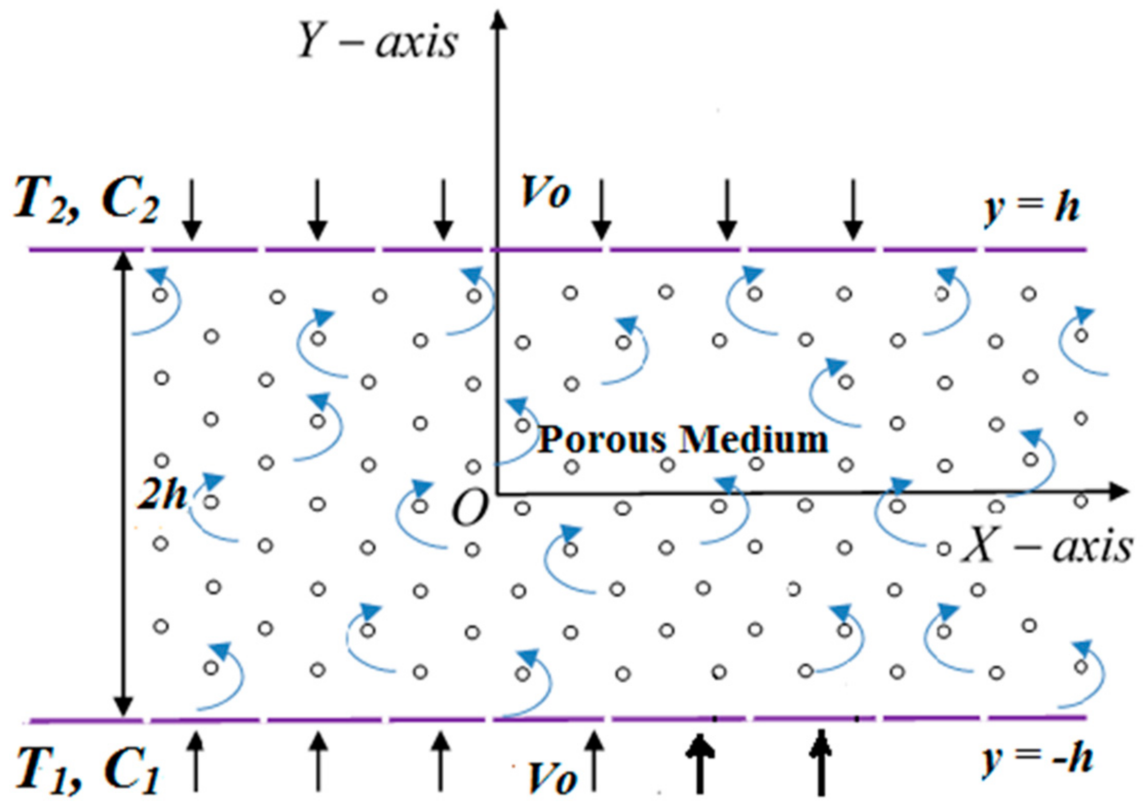
Here, we assume a two-dimensional, time-independent flow of a conducting micropolar fluid past a channel constructed by two permeable walls. The density of fluid has been taken as a constant throughout the analysis. The walls of the channel are taken corresponding to the x-axis, and d = 2 h represents channel width between two parallel walls with y = ± h (as shown in Figure 1). The flow is under the strong effects of the magnetic force and chemical reaction between the channel walls. The velocity of the flowing fluid is V = u , v , 0 along the x y -plane, accordingly.
The governing equations for the flow under the above-stated assumptions (following Ahmad et al. [31]) can be written as
v y + u x = 0
u u x + v u y = 1 ρ P x + μ + k ρ 2 u + k ρ N y μ + k ρ k * u σ B 0 2 ρ u
u v x + v v y = 1 ρ P y + μ + k ρ 2 v k ρ N x μ + k ρ k * v
ρ u N x + v N y = k j 2 N + u x v v y + μ s j 2 N x 2 + 2 N y 2
u T x + v T y = k 1 ρ C p 2 T y 2
u C x + v C y = D * 2 C y 2 R 0 C C 2
Here, the microrotational viscosity ( μ s ) is formulated as μ s = μ + k / 2 .
The boundary conditions controlling both walls of the channel are defined as
v = v 0 , u = 0 , T = T 1 , N = s u y y = h , C = C 1 a t   y = h v = v o , u = 0 , T = T 2 , N = s u y y = + h , C = C 2 a t   y = + h
In these boundary assumptions, s is referred to as a boundary parameter, and  v o > 0 describes the suction velocity, while  v o < 0 mentions the injection velocity. Here, we assume the case s = 0 pronounces the rotation free movement of micro-rotating particles in the vicinity of the porous walls of the channel [32]. Some other cases have also been discussed in the existing literature, for example s = 0.5 (weak concentrations) and s = 1.0 (turbulent flow).
We define the similarity transformation variables (succeeding Si et al. [33]) as
η = y h , ψ = v 0 x f ( η ) , θ ( η ) = T T 2 T 1 T 2 , N = v 0 x h 2 g ( η ) , ϕ ( η ) = C C 2 C 1 C 2 .
Here C 2   and   T 2 are defined as C 2 = B x + C 1 and T 2 = A x + T 1 containing A and  B as constants. The similarity variables given in Equation (8) identically verify the continuity Equation (1), while Equations (2)–(6) are transmuted to the following set of ordinary equations:
1 + C 1 f i v C 1 g Re f f + Re f f P 0 1 + C 1 f M 0 f = 0
C 2 g + C 1 f 2 g C 3 Re f g f g = 0
θ + P e h f θ f θ = 0
ϕ + P e m f ϕ P e m ( f ϕ + γ ϕ ) = 0
The corresponding boundary conditions after using transformations become
f = 1 : f = 0 , g = 0 , θ = 1 , ϕ = 1 ,   at   η = 1 f = 1 : f = 0 , g = 0 , θ = 0 , ϕ = 0 ,   at   η = + 1
The following are the non-dimensional parameters involved in the system of Equations (9)–(12):
P 0 = h 2 k , S c = ν D , M 0 = h 2 σ B 0 2 μ , C 1 = k / μ , Re = v 0 v h C 2 = μ s μ h 2 , Pr = υ ρ C p k 1 , γ = R 0 h v 0 , C 3 = j / h 2 , P e m = S c Re , P e h = Pr Re .
Furthermore, N u x —the local Nusselt number and S h x —the local Sherwood number are parameters of prime concern in many engineering processes, and these are defined by the following relations:
N u x = q y = h x T 1 T 2 k 1 = θ ( 1 ) , S h x = m y = h x C 1 C 2 k 1 = ϕ ( 1 ) .
In these relations, q —the local heat flux and m —the local mass flux are governing quantities in the heat and mass transfer analysis.

3. Quasi-Linearization Method

Quasi-linearization is an illustrious technique used to obtain the approximate solutions of nonlinear differential equations with quite a rapid convergence. The quasi-linearization method plays a fundamental role in solving complex nonlinear problems numerically. In addition, one can comment that this technique is a modified form of Newton’s method and can be applied to both boundary and initial value problems. Mostly, the problems comprising nonlinearities (convex or concave) are treated by the quasi-linearization method. Due to its frequent manipulations and implementations, the quasi-linearization technique is rather marvelous when contributing to an ancestry approach to attain the unique solutions of highly nonlinear boundary value problems.
We took the quasi-linearization method (QLM) for the quantization of the nonlinear equations. For this purpose, we formulated the unique sequences of the transformed vectors f z , g z , θ ( z ) and ϕ ( z ) , which iteratively converge to the approximate solution of Equations (9)–(12), correspondingly. Hence, Equation (9) was linearized by constructing the sequence of the velocity function f z . Consider a new function Q defined as
Re f f Re f f + f i v 1 + C 1 P 0 1 + C 1 f C 1 g M 0 f = Q ( f i v , f , f , f , f )
The new function Q was expanded by incorporating the Taylor-series expansion, and the higher-order terms were truncated by holding only the 1st order terms, thus we have
Q f ( z ) , f ( z ) , f ( z ) , f ( z ) , f ( z ) i v + f z + 1 f ( z ) Q f ( z ) + f z + 1 f ( z ) Q f ( z ) + f z + 1 f ( z ) Q f ( z ) + f z + 1 f ( z ) Q f ( z ) + f z + 1 i v f ( z ) i v Q f ( z ) i v = 0
After solving (15) and (16), we obtained
P 0 1 + C 1 M 0 + Re f z f z + 1 + Re f z f z + 1 + Re f z + 1 f z + 1 + C 1 f z + 1 i v = Re f z f z + f z f z + Re f z f z + 1 + C 1 g z
When substituting the derivatives in the ordinary differential Equation (17) using central differences, we attained the following equation for computing the sequence vector f z :
1 + C 1 + h Re f i z f i 2 z + 1 + 4 1 + C 1 2 h Re f i z + h Re 2 f i + 1 z f i 1 z P 0 1 + C 1 h 2 M 0 h 2 h Re 2 2 f i ( z ) + f i + 1 z + f i 1 z f i 1 ( z + 1 ) + 6 1 + C 1 h Re f i + 1 z f i 1 z + 2 P 0 1 + C 1 h 2 + 2 M 0 h 2 h Re f i + 2 z + 2 f i 1 z 2 f i + 1 ( z ) f i 2 z f i z + 1 + [ 4 1 + C 1 + 2 h Re f i z + h Re 2 f i + 1 z f i 1 z P 0 1 + C 1 h 2 M 0 h 2 + h Re 2 2 f i ( z ) + f i + 1 z + f i 1 z ] f i + 1 ( z + 1 ) + 1 + C 1 h Re f i z f i + 2 z + 1 = h Re 2 f i + 1 z f i 1 z f i + 1 z + f i 1 ( z ) 2 f i ( z ) h Re f i z f i + 2 z 2 f i + 1 ( z ) + 2 f i 1 z f i 2 z + h 2 C 1 g i + 1 z + g i 1 ( z ) 2 g i ( z )
Equations (10)–(12) were linearized in an analogous way. Consequently, we attained a system of the following equations for computing the sequence vectors g z ,   θ ( z ) and ϕ ( z ) :
C 2 g z + 1 C 1 f z + 2 g z + 1 = C 3 Re f z g z + 1 + f z g z + 1 θ z + 1 = P e h f z θ z + 1 + f z θ z + 1 ϕ z + 1 = P e m f z ϕ z + 1 + P e m ( f z ϕ z + 1 γ ϕ z + 1 )
The successive iterative technique was adopted (please see [34,35,36,37,38]) to acquire the approximate solutions of sequential systems (18) and (19) based on numerical algorithms.
  • The boundary conditions given in Equation (13) were satisfied by the provided initial guess f ( 0 ) ,   g ( 0 ) , θ ( 0 ) and ϕ ( 0 ) .
  • The linearized system specified in Equation (18) was solved to find f ( 1 ) .
  • The system of Equation (19) was discretized by finite differences and then solved, using known f ( 1 ) , to obtain g ( 1 ) , θ ( 1 ) and ϕ ( 1 ) .
  • Once the functions at the first level f ( 1 ) , g ( 1 ) , θ ( 1 ) and ϕ ( 1 ) were uniquely determined, the iterative process was reiterated in anticipation of the sequences f z , g z , θ ( z ) and ϕ ( z ) converging to vectors f , g , θ and ϕ , respectively.
  • The four sequences were repeatedly generated as far as
    max | | g z + 1 g z | | p 2 , | | f z + 1 f z | | p 2 < 10 8 & max | | θ z + 1 θ z | | p 2 , | | ϕ z + 1 ϕ z | | p 2 < T O L i t e r
For a better accuracy in the calculations, it was presumed that the value of T O L i t e r would be taken as at least 10 8 .

4. Comparison and Code Validation

In an attempt to evaluate the proficiency of the numerical code in the present problem, we drew a comparison to correlate our numerical results with the previously presented results in the literature of the related field (please see Table 1). An outstanding agreement was observed during the evaluation of the tabular data, which confirmed the validity and exactitude of our solution methodology and numerical code.
The dimensionless concentration profiles tend to fall in the flow regime with the impact of the Peclet number P e m , as portrayed in Figure 2. This comparison also validates the present code. It is noted here that the same results can be acquired by taking the same effects.

5. Results and Discussion

In the following section, we portray the numerical outcomes of the physical parameters through tables and graphs. The mass and heat transport rates, together with the shear stresses at both walls of the channel, are the physical quantities of primary interest and are proportionate to the values of ϕ ( ± 1 ) , θ ( ± 1 ) and f ( ± 1 ) , respectively. Additionally, we intend to examine the effects of the various parameters at the two walls of the channel for velocity, temperature, microrotation and concentration. The step of the non-dimensional coordinate η is so accustomed that all the distribution curves make evident asymptotic behavior. Moreover, the numerical results for the various steps of η at three different grids are enumerated in Table 2.
We take fixed values of the parameters (see Table 2) throughout the problem hereafter otherwise identified. 
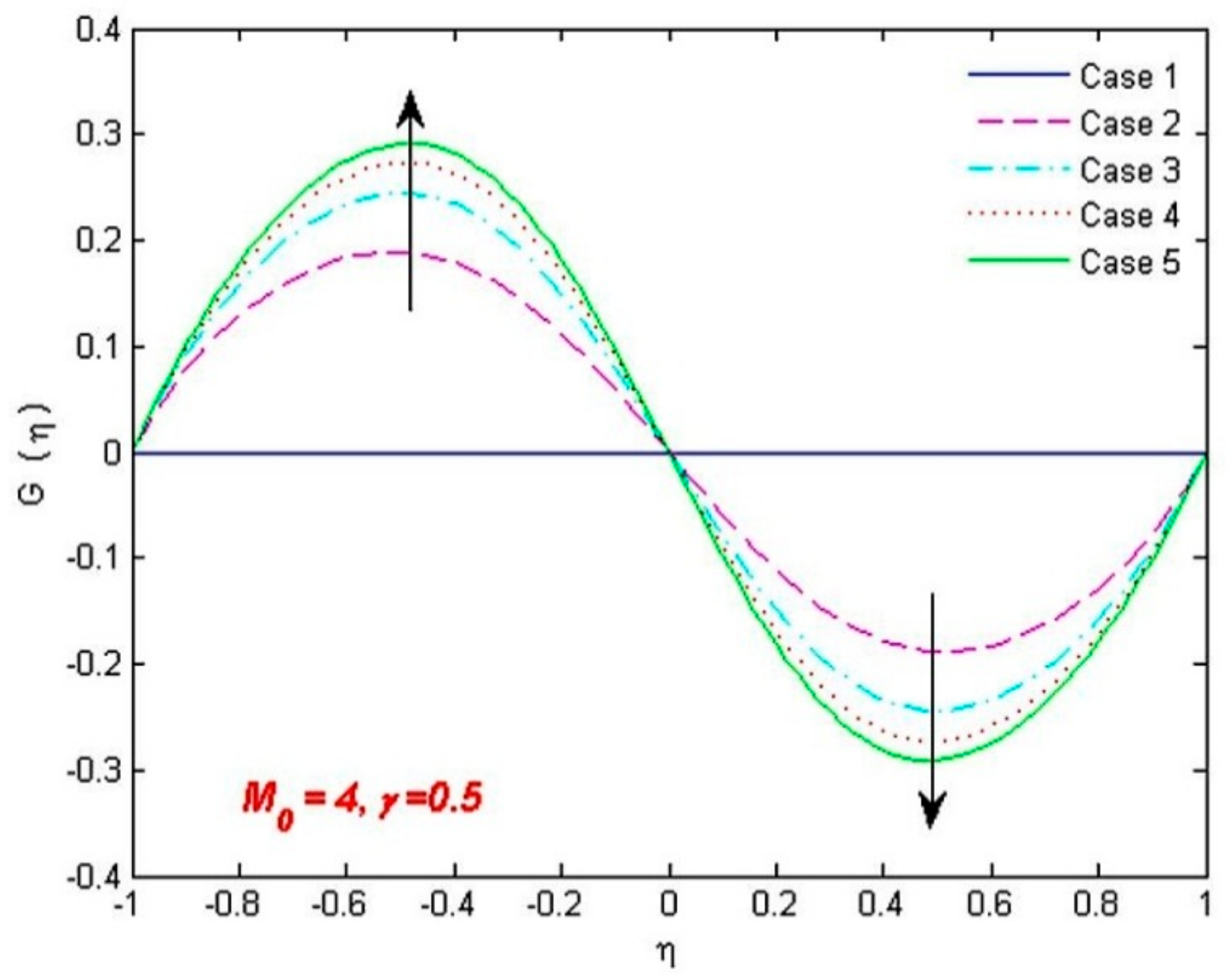
Figure 3 is drawn against microrotation as functions of η for the multiple values of micropolar material parameters C 1 , C 2 & C 3 (see Table 3). These parameters cause an enhancement in the microrotation of fluid.
The analyses of skin frictions, flow and heat transport on either wall of the channel with porosity effects for different values of material parameters are listed in Table 3. We take random values from the micropolar parameters other than the first case, where C 1 = C 2 = C 3 = 0 is taken for the Newtonian case to determine their combined impact on the flow, as described in [41,42,43,44,45]. Micropolar physical parameters tend to decrease the shear stresses and intensify the rates of heat transfer and mass flow. It is evident from this table that the mass and heat transport rates on both walls of the channel become enhanced, whereas the shear stresses become reduced with micropolar parameters. We may conclude that the microstructures of the fluid tend to reduce the surface drag, which is according to the experimental results of Hoyt and Fabula [1]. In addition, the role of the micro-constituents of micropolar fluid in producing very small heat and mass transport effects on either wall of the channel is due to the fact that the material parameters ( C 1 , C 2 , C 3 ) are not involved in the concentration and heat equations and, thus, do not interrupt the mass and heat transport features of the problem directly.
The variation of shear stresses, mass and thermal transmission rates on either wall of the porous channel with multiple values of the magnetic and porosity parameters are enumerated in Table 4 and Table 5, respectively. It is evident from the tabular data that the values of θ ( ± 1 ) and ϕ ( ± 1 ) are decreased and that f ( ± 1 ) increased with the effects of these parameters. The uniformity in the values of f ( 1 ) and f ( 1 ) on the upper and lower wall, respectively, is due to the same permeability ratios on the walls with opposite signs (e.g.,  v o and v o ). Due to this reason, the rates of heat and mass transfer are anti-symmetric on either wall of the channel. The magnetic parameter tends to raise the shear stresses, whereas it reduces the transportation rate of heat and mass on both walls. The magnetic field applies a frictional force that is recognized as the Lorentz force. By the virtue of body force behavior, it has a tendency to drag or shift the fluid towards the channel walls. This anomaly not only enhances skin friction but also tends to rotate microfluid particles rapidly at the walls. Moreover, the Lorentz force produces the temperature difference (between the temperature at channel walls and the temperature of fluid) and, hence, decreases the heat transport at both walls. The magnetic as well as the porosity parameter inserts a low effect on the mass transfer rates ϕ ( 1 ) and ϕ ( 1 ) , and heat transfer rates θ ( 1 ) and θ ( 1 ) .
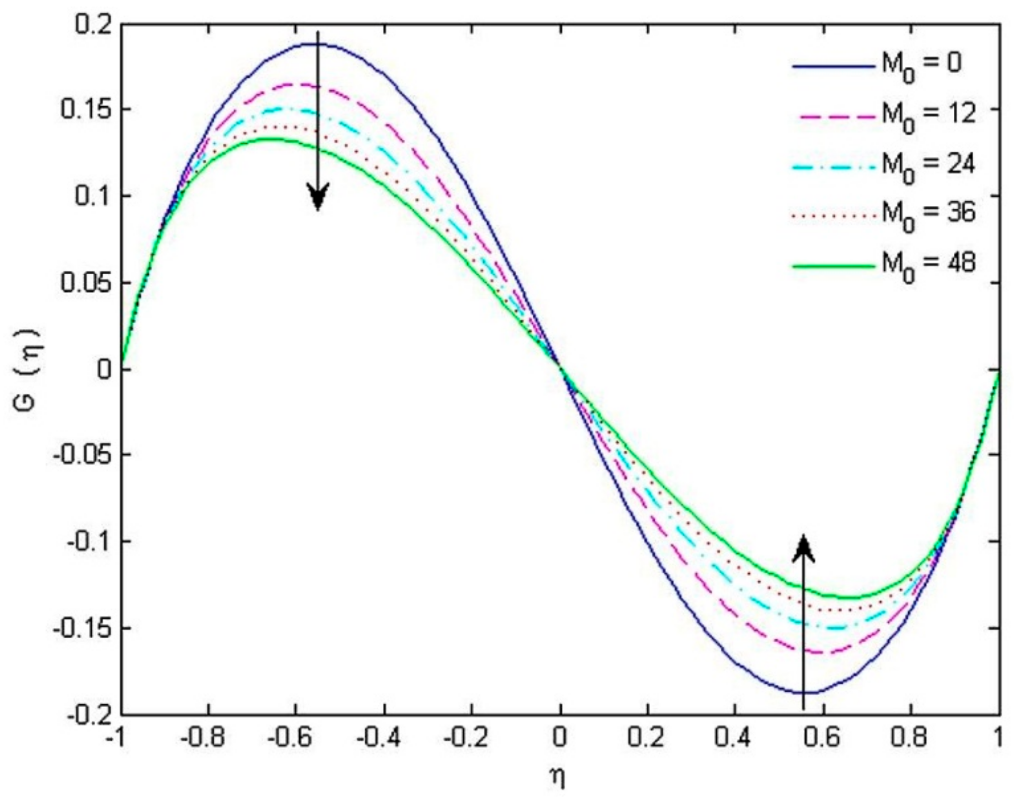
The impacts of the magnetic parameter M 0 and the porosity parameter P 0 on the microrotation and velocity are portrayed in Figure 4 and 
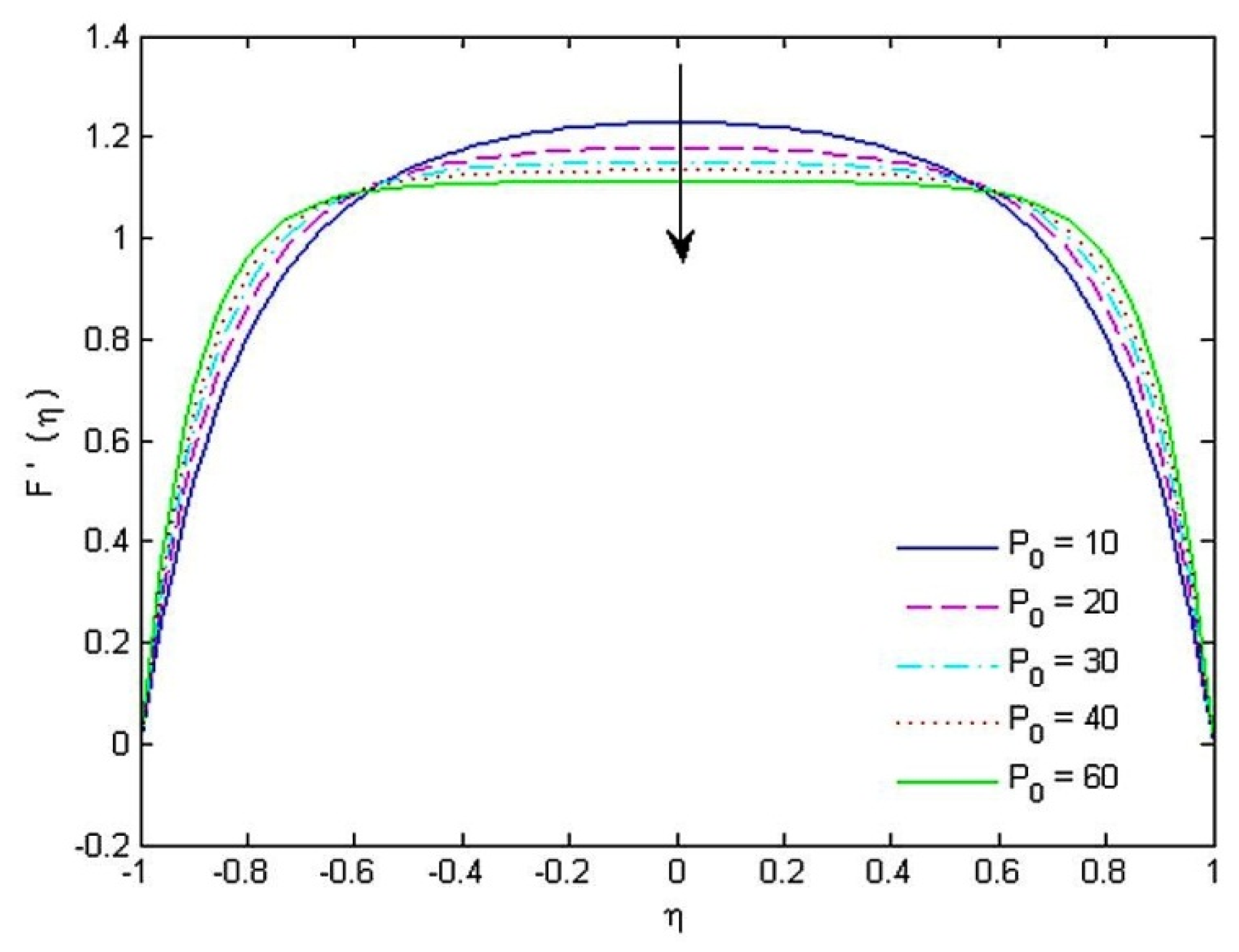
Figure 5, respectively. The angular velocity profile changes the concavity somewhere near the midpoint of the channel for the magnetic parameter. Material parameters tend to increase the streamwise velocity near the upper wall while the other parameters produce opposite effects on the velocity due to the permeability of the upper wall, which drives streamwise moving fluid beyond the wall and causes a decrease in velocity near the upper wall. The reduction in velocity F ( η ) (see Figure 5) happens by enhancing the surface permeability of the channel. Rational reasoning for such a diminishing tendency is linked with the sizes of pores inside the permeable walls. Consequently, a repellant force from the reverse direction of the flow field reacts with the fluid and, as a result, the velocity boundary layer thickness decreases. It is profound that the angular velocity G ( η ) decelerates near the lower and upper walls by augmenting the values of magnetic parameter M 0 , whereas an enhancement in the microrotation near both walls is noticed with an increase in C 1 , C 2 & C 3 . Nevertheless, the material parameters and the porosity parameter have no significant effect on the concentration and temperature.
The impacts of the parameters such as P e h , P e m and γ on heat and mass transmission rates can be examined in Table 6. The mass transport rate drops at the upper wall and grows at the lower wall with the influence of chemical reactions. The values of θ ( 1 ) decrease and that of θ ( 1 ) enhance with the effect of P e h . Likewise, an increment in the Peclet number P e m causes an increase in the rate of mass transfer on the upper channel wall and decreases the mass transfer rate on the lower channel.
It is observed here that the heat and mass transfer rates tend to increase for both Peclet numbers (e.g., heat and mass) on the upper wall and decrease on the lower channel wall. Additionally, both parameters P e m and P e h are proportional to each other in case of the heat and mass transport rates. It may be better to mention here that the effect of the porosity parameter is more dominant on the skin friction rather than its effect on heat and mass transfer rates. We can attain heat and mass transfer rates by our own choice from appropriately choosing the suction/injection velocity and other parametric values. In this way, we can attain desirable consequences in industrial employments.
The angular velocity profile for the micropolar parameters is concave downward in the lower half of the channel and concave upward in the upper half of the channel. When C 1 = C 2 = C 3 = 0 at both permeable walls, the effect of skin frictions equally spreads from the walls such that the angular velocity (microrotation) is zero at the center of the channel (see Figure 3). The angular velocity gets reduced with the effect of porosity and magnetic parameters at the upper as well as lower channel wall when 0.4 < η < 0.8 and 0.4 < η < 0.8 , respectively. Contrarily, the microrotation gets enhanced with the micropolar material parameters near both walls when 0.4 < η < 0.8 and 0.4 < η < 0.8 
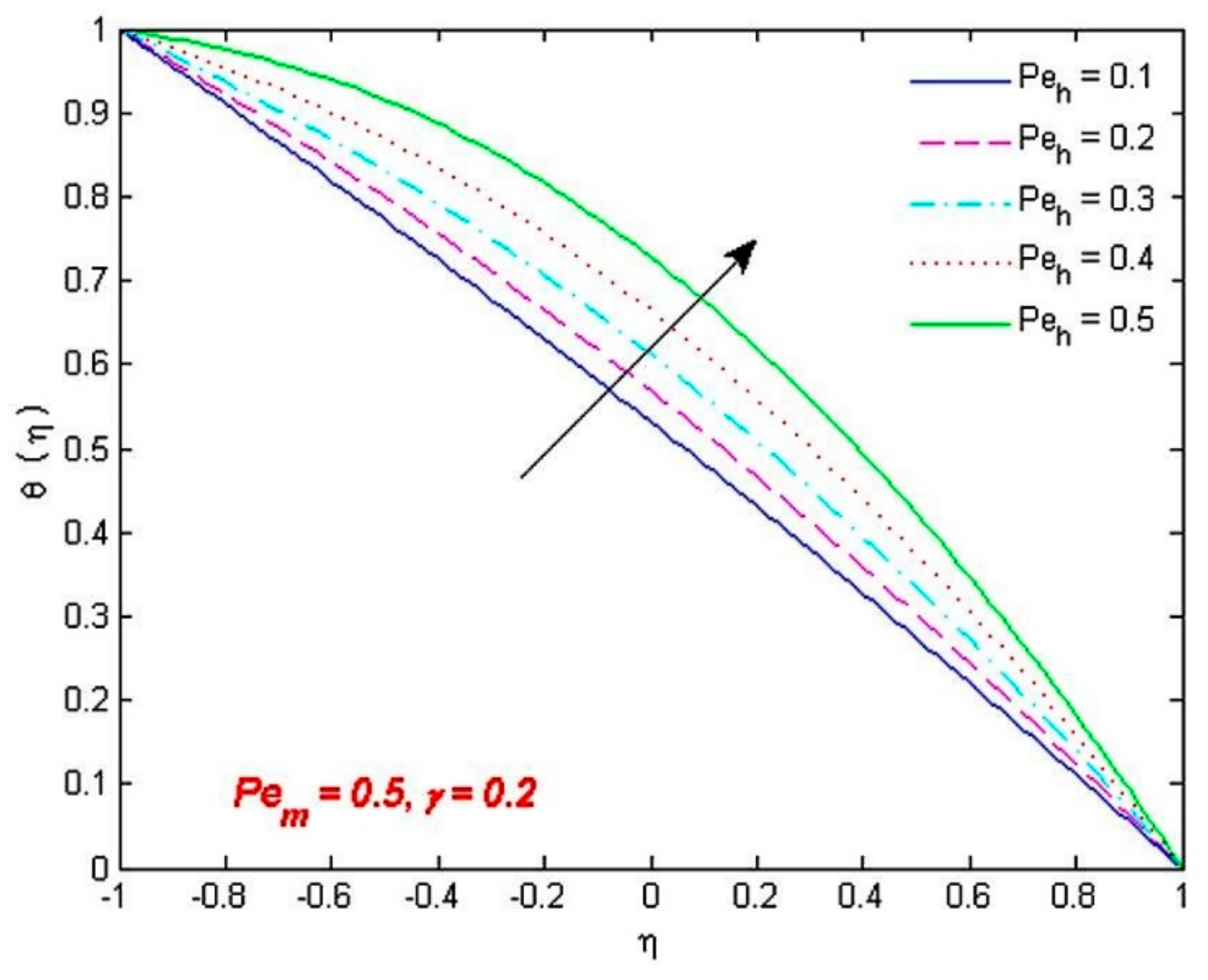
. The surface drag caused by the micropolar fluid tends to rotate the fluid on the two walls in opposite directions. Due to this reason, microrotation adjacent to either wall of the channel possesses opposite signs. The temperature
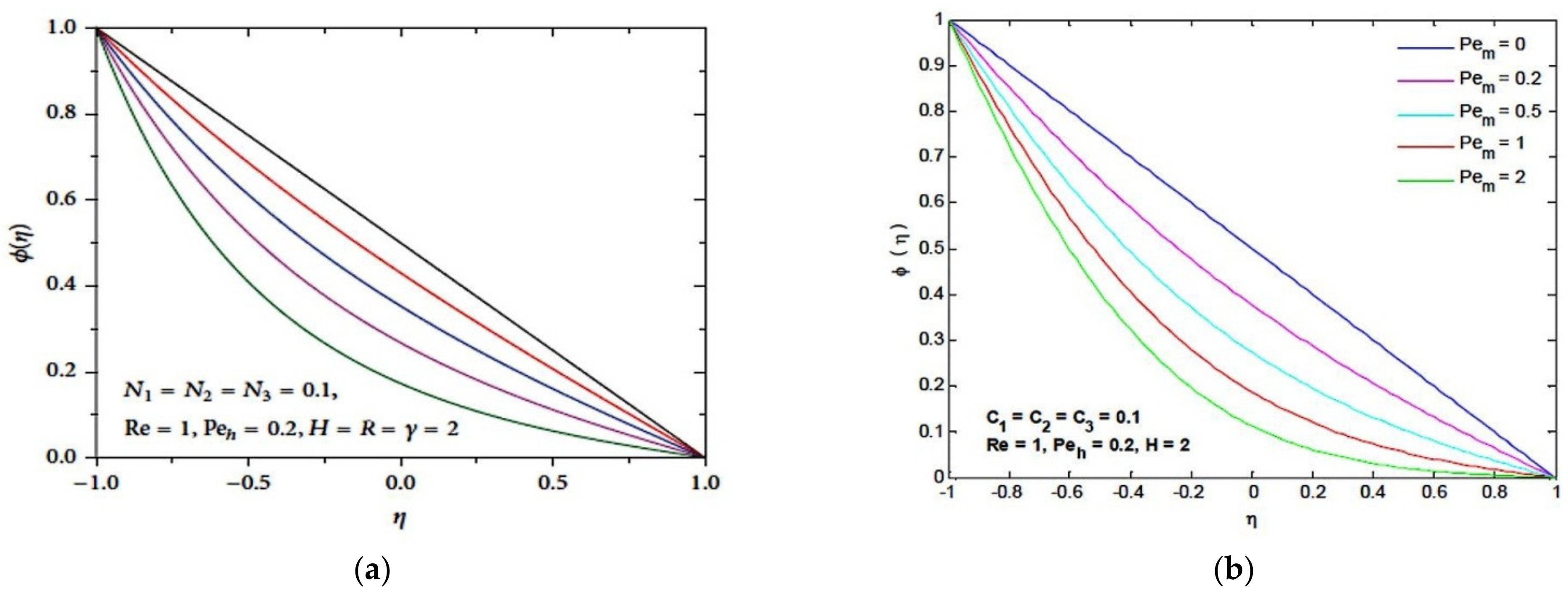
 θ is portrayed in Figure 6 for diverse estimations of the Peclet number P e h as a function of the coordinate 
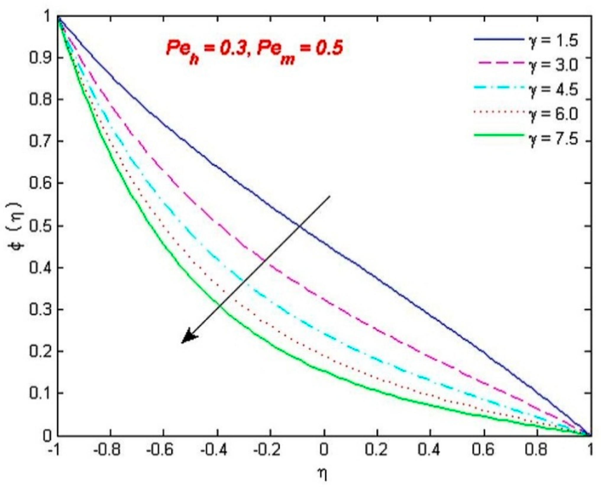
η. It is seen that the temperature is elevated with the effect of this parameter. The consequences of Figure 7 illustrate how the chemical reaction parameter γ tends to downturn the concentration ϕ ( η ) .

6. Concluding Remarks

An inclusive computational analysis of the non-Newtonian MHD micropolar fluid flow is presented in this paper. The novel aspects of the present work can be characterized as follows:
(i)
The behavior of the micro structure of the fluid on the suction/injection driven flow pattern in the channel is discussed in our work, which is not discussed in earlier literature. Furthermore, a non-Newtonian permeable channel flow in the magnetohydrodynamic environment has not been explored numerically using our proposed numerical technique.
(ii)
We have considered the flow within a channel as having two porous or permeable walls. We have also considered a porous medium between the walls of the channel. By simultaneously taking porous walls and a porous medium between these walls is also a novelty in our work. The use of a porous medium plays a pivotal role in maintaining the flow, which adjusts the heat transport rate and thus alters the temperature distribution as required.
(iii)
Another novelty is to assign a zero value to the boundary parameter, that is, a rotation free movement of particles is assumed in proximity to the channel walls.
(iv)
A persuasive numerical algorithm is developed, which can solve highly nonlinear differential equations efficiently.
The flow is measured between the walls of a permeable channel under the influence of a chemical reaction. The numerical results are explained with the help of graphs and tables. The main consequences of this study are listed below:
  • The angular velocity is accelerated with the material parameters, while the magnetic parameter yields the opposite effects.
  • The surface drag is magnified by the porosity parameter, but mass and thermal transport rates are reduced on either wall of the channel with its effect.
  • The porosity as well as the material parameters insert low effects on the rates of flow and thermal transmission on the lower and upper walls.
  • The increasing values of the mass transfer rate are associated with the chemical reaction parameter, which causes an increment in the mass transfer at the lower wall of the porous channel.

Author Contributions

Conceptualization, S.A. and K.A.; methodology, A.A.F.; software, K.A.; validation, S.A., A.A.F. and W.J.; formal analysis, K.A., N.K., A.-H.A.-A. and I.S.Y.; investigation, W.J., A.-H.A.-A. and I.S.Y.; resources, S.A.; data curation, A.A.F.; writing—original draft preparation, S.A., K.A., K.S.N., A.A.F. and N.K.; writing—review and editing, S.A.; visualization, A.A.F.; supervision, K.A. and N.K.; project administration, K.S.N.; funding acquisition, A.-H.A.-A. and I.S.Y. All authors have read and agreed to the published version of the manuscript.

Funding

This work was funded by Research Center for Advanced Materials Science (RCAMS)” at King Khalid University, Abha, Saudi Arabia, grant number RCAMS/KKU/019-20.

Institutional Review Board Statement

Not applicable.

Informed Consent Statement

Not applicable.

Data Availability Statement

Data will be provided by the authors on request.

Acknowledgments

The authors express their appreciation to “The Research Center for Advanced Materials Science (RCAMS)” at King Khalid University, Saudi Arabia, for funding this work under the grant number RCAMS/KKU/019-20.

Conflicts of Interest

The authors declare no conflict of interest.

Nomenclature

P Pressure (N·m−2) k permeability of the medium
Re Reynolds number S c Schmidt number
C p specific heat at constant pressure (Jmol−1·k−1) k 1 thermal conductivity (W·m−1·k−1)
Pr Prandtl number f dimensionless function
D molecular diffusivity (m2·s−1) C fluid concentration (mol−1·m−3)
g dimensionless microrotation μ fluid viscosity (kg·m−1·s−1)
N angular velocity (m·s−1) R 0 chemical reaction rate (mol−1·m−3·s−1)
P 0 porosity parameter M 0 magnetic parameter
ρ fluid density (kg·m−3) ψ stream function (m2·s−1))
j microinertia density (m2) k vortex viscosity
θ dimensionless temperature ϕ dimensionless concentration
P e h Peclet number for heat diffusion P e m Peclet number for mass diffusion
μ s microrotational viscosity η similarity variable
C 1 dimensionless vortex viscosity C 2 dimensionless spin-gradient viscosity
C 3 dimensionless microinertia density ( x , y ) Cartesian coordinate component parallel and normal to channel axis, respectively
γ dimensionless reaction rate

References

  1. Hoyt, J.W.; Fabula, A.G. The Effect of Additives on Fluid Friction; Defense Technical Information Center: Dayton, OH, USA, 1964; pp. 1–31. [Google Scholar]
  2. Ariman, T.; Turk, M.A.; Sylvester, N.D. Microcontinuum fluid mechanics—A review. Int. J. Eng. Sci. 1973, 11, 905–930. [Google Scholar] [CrossRef]
  3. Eringen, A.C. Theory of micropolar fluids. J. Math. Mech. 1966, 16, 1–18. [Google Scholar] [CrossRef]
  4. Hadimoto, B.; Tikioka, T. Two dimensional shear flows of linear micropolar fluids. Int. J. Eng. Sci. 1969, 7, 515–522. [Google Scholar]
  5. Perdikis, C.; Raptis, A. Heat transfer of a micropolar fluid by the presence of radiation. Heat Mass Transf. 1996, 31, 381–382. [Google Scholar] [CrossRef]
  6. Bakr, A.A. Effects of chemical reaction on MHD free convection and mass transfer flow of a micropolar fluid with oscillatory plate velocity and constant heat source in a rotating frame of reference. Commun. Nonlinear Sci. Numer. Simul. 2011, 16, 698–710. [Google Scholar] [CrossRef]
  7. Lockwood, F.E.; Benchaita, M.T.; Friberg, S.E. Study of lyotropic liquid crystal in viscometric flow and elastohydrodynamics contact. Tribol. Trans. 1986, 30, 539–548. [Google Scholar] [CrossRef]
  8. Dupuy, D.; Panasenko, G.P.; Stavre, R. Asymptotic methods for micropolar fluids in a tube structure. Math. Models Methods Appl. Sci. 2004, 14, 735–758. [Google Scholar] [CrossRef]
  9. Dupuy, D.; Panasenko, G.P.; Stavre, R. Asymptotic solution for a micropolar flow in a curvilinear channel. ZAMM-J. Appl. Math. Mech. Z. Angew. Math. Mech. Appl. Math. Mech. 2008, 88, 793–807. [Google Scholar] [CrossRef]
  10. Pažanin, I. Effective flow of micropolar fluid through a thin or long pipe. Math. Probl. Eng. 2011, 2011, 127070. [Google Scholar] [CrossRef] [Green Version]
  11. Yadav, P.K.; Jaiswal, S.; Sharma, B.D. Mathematical model of micropolar fluid in two-phase immiscible fluid flow through porous channel. Appl. Math. Mech. 2018, 39, 993–1006. [Google Scholar] [CrossRef]
  12. Si, X.; Zheng, L.; Zhang, X.; Chao, Y. The flow of a micropolar fluid through a porous channel with expanding or contracting walls. Open Phys. 2011, 9, 825–834. [Google Scholar] [CrossRef]
  13. Chang, H.N.; Ha, J.S.; Park, J.K.; Kim, I.H.; Shin, H.D. Velocity field of pulsatile flow in a porous tube. J. Biomech. 1989, 22, 1257–1262. [Google Scholar] [CrossRef]
  14. Uchida, S.; Aoki, H. Unsteady flows in a semi-infinite contracting or expanding pipe. J. Fluid Mech. 1977, 82, 371. [Google Scholar] [CrossRef]
  15. Ohki, M.B. Unsteady flow in a porous, elastic, circular tube Part-I. Bull. JSME 1980, 23, 679. [Google Scholar] [CrossRef] [Green Version]
  16. Singh, K.; Pandey, A.K.; Kumar, M. Numerical solution of micropolar fluid flow via stretchable surface with chemical reaction and melting heat transfer using Keller-Box method. Propuls. Power Res. 2021, 10, 194–207. [Google Scholar] [CrossRef]
  17. Bujurke, N.M.; Pai, N.P.; Jayaraman, G. Computer extended series solution for unsteady flow in a contracting or expanding pipe. IMA J. Appl. Math. 1998, 60, 151–165. [Google Scholar] [CrossRef]
  18. Shamshuddin, M.; Thirupathi, T.; Narayana, P.S. Micropolar fluid flow induced due to a stretching sheet with heat source/sink and surface heat flux boundary condition effects. J. Appl. Comput. Mech. 2019, 5, 816–826. [Google Scholar]
  19. Ghadikolaei, S.S.; Hosseinzadeh, K.; Yassari, M.; Sadeghi, H.; Ganji, D.D. Boundary layer analysis of micropolar dusty fluid with TiO2 nanoparticles in a porous medium under the effect of magnetic field and thermal radiation over a stretching sheet. J. Mol. Liq. 2017, 244, 374–389. [Google Scholar] [CrossRef]
  20. Van Gorder, R.A.; Vajravelu, K.; Pop, I. Hydromagnetic stagnation point flow of a viscous fluid over a stretching or shrinking sheet. Meccanica 2012, 47, 31–50. [Google Scholar] [CrossRef]
  21. Kameswaran, P.K.; Narayana, M.; Sibanda, P.; Murthy, P.V.S.N. Hydromagnetic nanofluid flow due to a stretching or shrinking sheet with viscous dissipation and chemical reaction effects. Int. J. Heat Mass Transf. 2012, 55, 7587–7595. [Google Scholar] [CrossRef]
  22. Kameswaran, P.K.; Shaw, S.; Sibanda, P.; Murthy, P.V.S.N. Homogeneous-heterogeneous reactions in a nanofluid flow due to a porous stretching sheet. Int. J. Heat Mass Transf. 2013, 57, 465–472. [Google Scholar] [CrossRef]
  23. Borrelli, A.; Giantesio, G.; Patria, M.C. MHD oblique stagnation-point flow of a micropolar fluid. Appl. Math. Model. 2012, 36, 3949–3970. [Google Scholar] [CrossRef]
  24. Eldabe, N.T.; Ouaf, M.E.M. Chebyshev finite difference method for heat and mass transfer in a hydromagnetic flow of a micropolar fluid past a stretching surface with Ohmic heating and viscous dissipation. Appl. Math. Comput. 2006, 177, 561–571. [Google Scholar] [CrossRef]
  25. Mishra, S.R.; Hoque, M.M.; Mohanty, B.; Anika, N.N. Heat transfer effect on MHD flow of a micropolar fluid through porous medium with uniform heat source and radiation. Nonlinear Eng. 2019, 8, 65–73. [Google Scholar] [CrossRef]
  26. Prakash, D.; Muthtamilselvan, M. Effect of radiation on transient MHD flow of micropolar fluid between porous vertical channel with boundary conditions of the third kind. Ain Shams Eng. J. 2014, 5, 1277–1286. [Google Scholar] [CrossRef] [Green Version]
  27. Rashidi, M.M.; Keimanesh, M. Using differential transform method and Pade approximant for solving MHD flow in a laminar liquid film from a horizontal stretching surface. Math. Probl. Eng. 2010, 2010, 491319. [Google Scholar] [CrossRef]
  28. Rashidi, M.M.; Pour, S.A.M.; Hayat, T.; Obaidat, S. Analytic approximate solutions for steady flow over a rotating disk in porous medium with heat transfer by homotopy analysis method. Comput. Fluids 2012, 54, 1–9. [Google Scholar] [CrossRef]
  29. Rashidi, M.M.; Hayat, T.; Keimanesh, M.; Yousefian, H. A study on heat transfer in a second-grade fluid through a porous medium with the modified differential transform method. Heat Transf. Asian Res. 2013, 42, 31–45. [Google Scholar] [CrossRef]
  30. Umavathi, J.C.; Sultana, J. Mixed convective flow of a micropolar fluid mixture in a vertical channel with boundary conditions of the third kind. J. Eng. Phys. Thermophys. 2012, 85, 895–908. [Google Scholar] [CrossRef]
  31. Ahmad, S.; Ashraf, M.; Ali, K. Simulation of thermal radiation in a micropolar fluid flow through a porous medium between channel walls. J. Therm. Anal. Calorim. 2021, 144, 941–953. [Google Scholar] [CrossRef]
  32. Ziabakhsh, Z.; Domairry, G. Homotopy analysis solution of micro-polar flow in a porous channel with high mass transfer. Adv. Theor. Appl. Mech. 2008, 1, 79–94. [Google Scholar]
  33. Si, X.; Zheng, L.; Ping, L.; Zhang, X.; Zhang, Y. Flow and heat transfer of a micropolar fluid in a porous channel with expanding or contracting walls. Int. J. Heat Mass Transf. 2013, 67, 885–895. [Google Scholar] [CrossRef]
  34. Ahmad, S.; Ali, K.; Nisar, K.S.; Faridi, A.A.; Khan, N.; Jamshed, W.; Khan, T.M.Y.; Saleel, C.A. Features of Cu and TiO2 in the flow of engine oil subject to thermal jump conditions. Sci. Rep. 2021, 11, 19592. [Google Scholar] [CrossRef]
  35. Ahmad, S.; Ali, K.; Faridi, A.A.; Ashraf, M. Novel thermal aspects of hybrid nanoparticles Cu-TiO2 in the flow of Ethylene Glycol. Int. Commun. Heat Mass Transf. 2021, 129, 105708. [Google Scholar] [CrossRef]
  36. Ahmad, S.; Ali, K.; Rizwan, M.; Ashraf, M. Heat and mass transfer attributes of Copper-Aluminum oxide hybrid nanoparticles flow through a porous medium. Case Stud. Therm. Eng. 2021, 25, 100932. [Google Scholar] [CrossRef]
  37. Ahmad, S.; Ali, K.; Ashraf, M. MHD flow of Cu-Al2O3/water hybrid nanofluid through a porous media. J. Porous Media 2021, 24, 61–73. [Google Scholar] [CrossRef]
  38. Ali, K.; Ahmad, S.; Nisar, K.S.; Faridi, A.A.; Ashraf, M. Simulation analysis of MHD hybrid Cu-Al2O3/H2O nanofluid flow with heat generation through a porous media. Int. J. Energy Res. 2021, 45, 19165–19179. [Google Scholar] [CrossRef]
  39. Mirzaaghaian, A.; Ganji, D.D. Application of differential transformation method in micropolar fluid flow and heat transfer through permeable walls. Alex. Eng. J. 2016, 55, 2183–2191. [Google Scholar] [CrossRef] [Green Version]
  40. Singh, K.; Kumar, M. Influence of chemical reaction on heat and mass transfer flow of a micropolar fluid over a permeable channel with radiation and heat generation. J. Thermodyn. 2016, 2016, 8307980. [Google Scholar] [CrossRef] [Green Version]
  41. Ashraf, M.; Anwar, K.M.; Syed, K.S. Numerical investigations of asymmetric flow of a micropolar fluid between two porous disks. Acta Mech. Sin. 2009, 25, 787–794. [Google Scholar] [CrossRef]
  42. Ahmad, S.; Ashraf, M.; Ali, K. Numerical simulation of viscous dissipation in a micropolar fluid flow through a porous medium. J. Appl. Mech. Tech. Phys. 2019, 60, 996–1004. [Google Scholar] [CrossRef]
  43. Ahmad, S.; Ashraf, M.; Ali, K. Micropolar fluid flow with heat generation through a porous medium. Punjab Univ. J. Math. 2020, 52, 101–113. [Google Scholar]
  44. Ahmad, S.; Ali, K.; Ahmad, S.; Cai, J. Numerical study of Lorentz force interaction with micro structure in channel flow. Energies 2021, 14, 4286. [Google Scholar] [CrossRef]
  45. Ahmad, S.; Ashraf, M.; Ali, K.; Nisar, K.S. Computational analysis of heat and mass transfer in a micropolar fluid flow through a porous medium between permeable channel walls. Int. J. Nonlinear Sci. Numer. Simul. 2021. [Google Scholar] [CrossRef]
Figure 1. Geometry of the channel flow.
Coatings 12 00093 g001
Figure 2. Comparison with concentration distribution ϕ ( η ) for several values of P e m . (a) Singh and Kumar [40]; (b) Present case.
Coatings 12 00093 g002
Figure 3. Change in angular velocity for various values of C 1 , C 2 and C 3 (shown in Table 3).
Coatings 12 00093 g003
Figure 4. Change in angular velocity for various values of magnetic parameter M 0 .
Coatings 12 00093 g004
Figure 5. Change in velocity for various values of porosity parameter P 0 .
Coatings 12 00093 g005
Figure 6. Change in temperature for various values of Peclet number for the diffusion of heat P e h .
Coatings 12 00093 g006
Figure 7. Change in concentration for various values of chemical reaction parameter γ .
Coatings 12 00093 g007
Table 1. Comparison of microrotation g and velocity f against different values of η when P e m = Re = P e h = C 1 = C 2 = C 3 = 0.1 and P 0 = γ = M 0 = 0 .
η g f
Ahmad et al. [31]Mirzaaghaian and Ganji [39]Present ResultsAhmad et al. [31]Mirzaaghaian and Ganji [39]Present Results
−1.0000−1−1−1
−0.60.1609470.1619850.160947−0.791599−0.791757−0.791599
−0.20.0786670.0782790.078667−0.295686−0.295835−0.295686
0.2−0.078668−0.078289−0.0786680.2956860.2958350.295686
0.6−0.160947−0.161985−0.1609470.7915990.7917570.791599
1.0000111
Table 2. Non-dimensional values of concentration ϕ ( η ) on three grid sizes for Re = 6 , M 0 = 2 , C 1 = 1.2 , P 0 = 3 , C 2 = 0.8 , P e h = 0.2 , C 3 = 0.4 , P e m = 0.3 , γ = 0.6 .
η ϕ ( η )
III-Grid (h = 0.0025)II-Grid (h = 0.005)I-Grid (h = 0.01)
1111
−0.80.9089520.9089520.908951
−0.60.8218050.8218070.821817
00.5503360.5503450.550380
0.60.2384070.2384130.238435
0.80.1225820.1225850.122597
0000
Table 3. Shear stresses, heat and mass transfer rates for various values of C 1 , C 2 & C 3 .
Cases f ( 1 )   f ( 1 ) θ ( 1 ) θ ( 1 ) ϕ ( 1 ) ϕ ( 1 )
1. Newtonian (C1 = C2 = C3 = 0)9.923697−9.923697−0.390444−0.627010−0.447160−0.631785
2. (C1 = 1.2, C2 = 0.8, C3 = 0.6)5.488327−5.488327−0.394093−0.635162−0.452590−0.644151
3. (C1 = 2.2, C2 = 1.2, C3 = 0.9)4.566625−4.566625−0.395171−0.637767−0.454147−0.648142
4. (C1 = 3.2, C2 = 1.6, C3 = 1.2)4.152741−4.152741−0.395710−0.639111−0.454915−0.650208
5. (C1 = 4.2, C2 = 2.0, C3 = 1.5)3.923353−3.923353−0.396027−0.639914−0.455363−0.651446
Table 4. Shear stresses, heat and mass transfer rates for various values of M 0 .
M 0   f ( 1 )   f ( 1 ) θ ( 1 ) θ ( 1 ) ϕ ( 1 ) ϕ ( 1 )
05.143071−5.143071−0.394512−0.636166−0.477787−0.631427
126.097594−6.097594−0.393335−0.633379−0.4759310.627328
246.791319−6.791319−0.392571−0.631631−0.474717−0.624766
367.347998−7.347998−0.392019−0.630395−0.473835−0.622959
487.820043−7.820043−0.391593−0.629456−0.473152−0.621589
Table 5. Shear stresses, heat and mass transfer rates for various values of P 0 .
P 0   f ( 1 )   f ( 1 ) θ ( 1 ) θ ( 1 ) ϕ ( 1 ) ϕ ( 1 )
106.431992−6.431992−0.392956−0.632507−0.475330−0.626049
207.488875−7.488875−0.391888−0.630105−0.473625−0.622535
308.279507−8.279507−0.391214−0.628629−0.472541−0.620384
408.928510−8.928510−0.390731−0.627592−0.471761−0.618873
609.982604−9.982604−0.390059−0.626175−0.470674−0.616813
Table 6. Heat and mass transfer rates for various values of P e h , P e m and γ .
P e h θ ( 1 ) θ ( 1 ) P e m ϕ ( 1 ) ϕ ( 1 ) γ ϕ ( 1 ) ϕ ( 1 )
0.1−0.452602−0.5621500.0−0.500000−0.4999991.5−0.805151−0.532568
0.2−0.394271−0.6355850.1−0.467187−0.5543453.0−1.241151−0.331985
0.3−0.321936−0.7233880.3−0.376018−0.6903694.5−1.566738−0.221562
0.4−0.231307−0.8298560.5−0.234295−0.8794476.0−1.832003−0.154722
0.5−0.116209−0.9611770.7−0.006780−1.1569617.5−2.059481−0.111640
Publisher’s Note: MDPI stays neutral with regard to jurisdictional claims in published maps and institutional affiliations.

