
Optimization of the Active Layer P3HT:PCBM for Organic Solar Cell


Abstract
:1. Introduction
2. Experimental Part
2.1. Materials
2.2. Solution Preparation
2.3. OSC Fabrication
2.4. OSC Characterization and Experimental Measurements
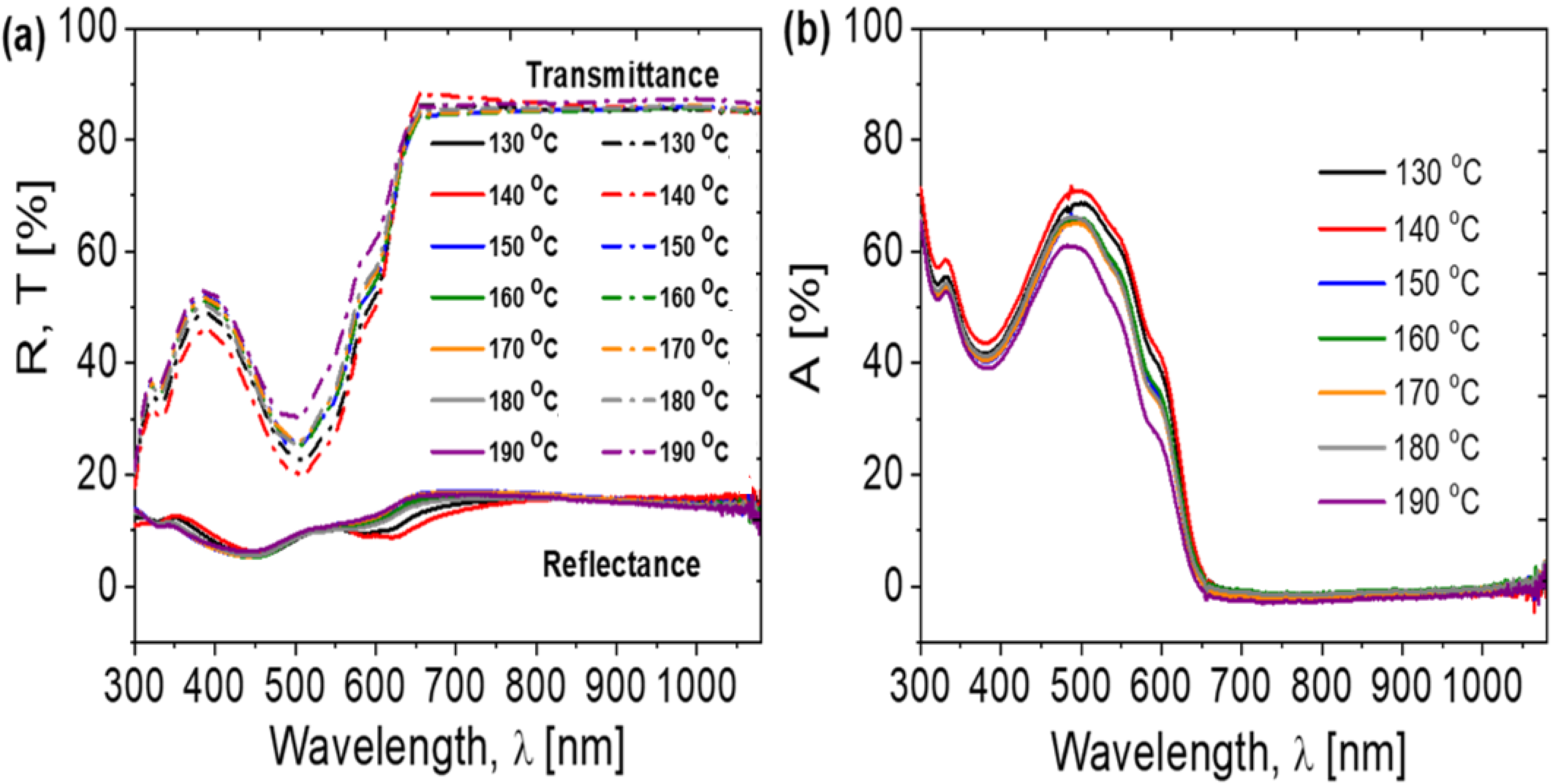
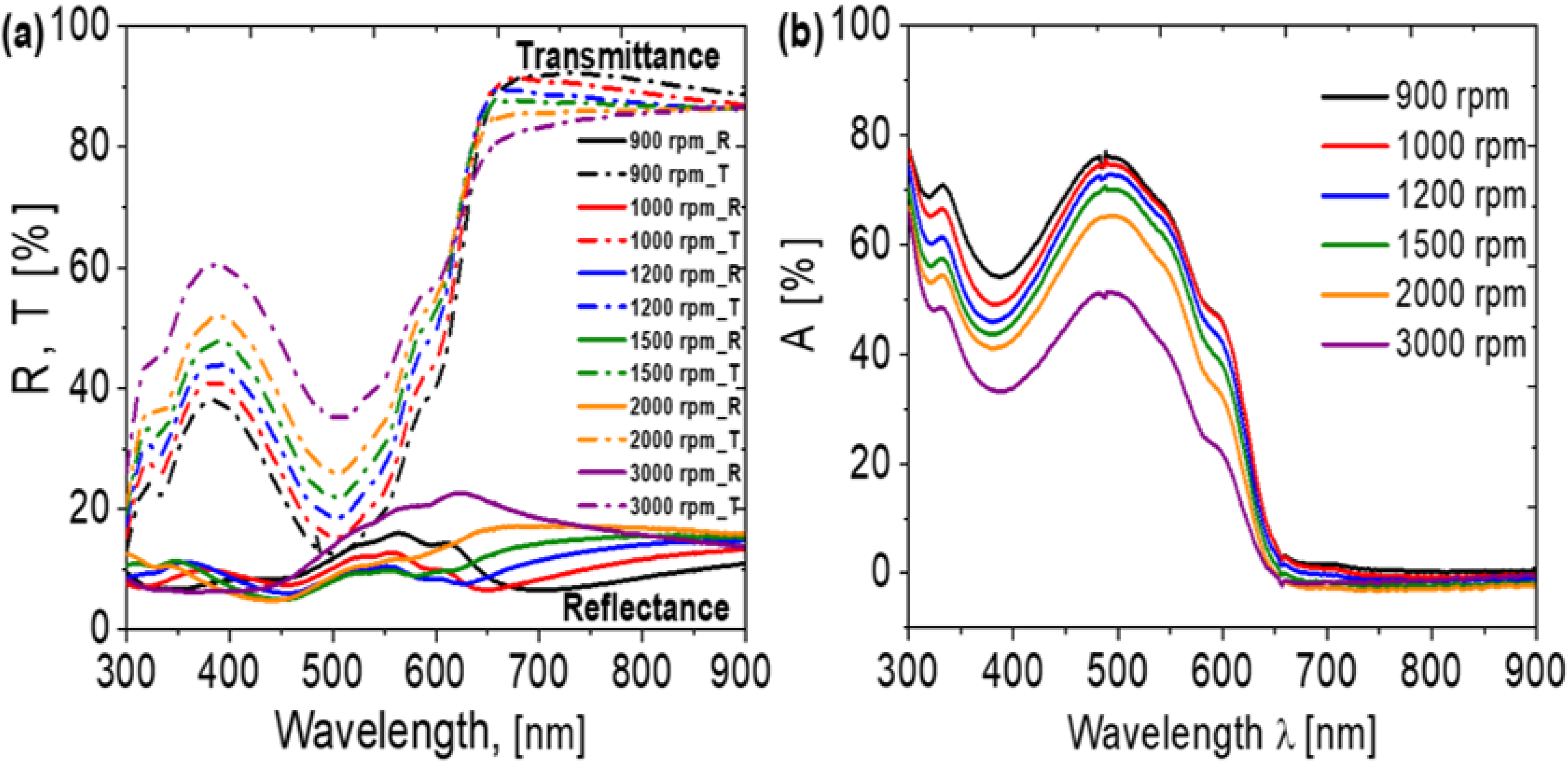
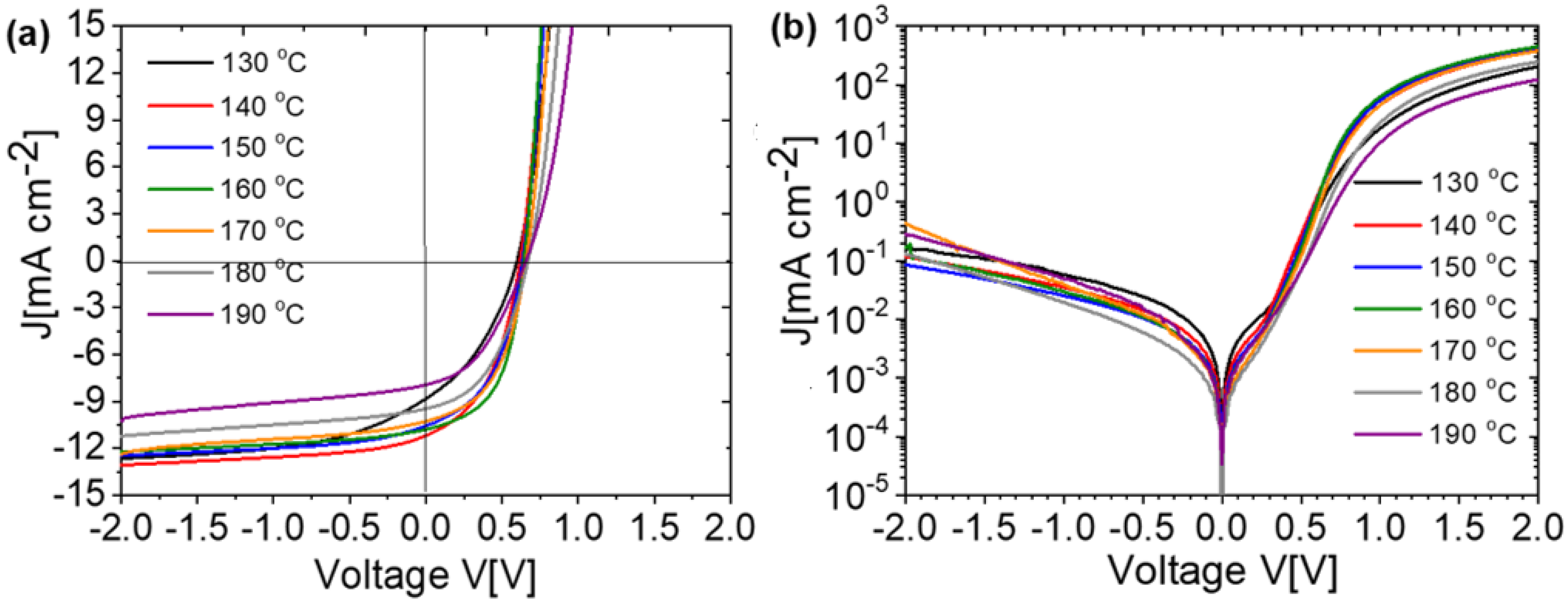
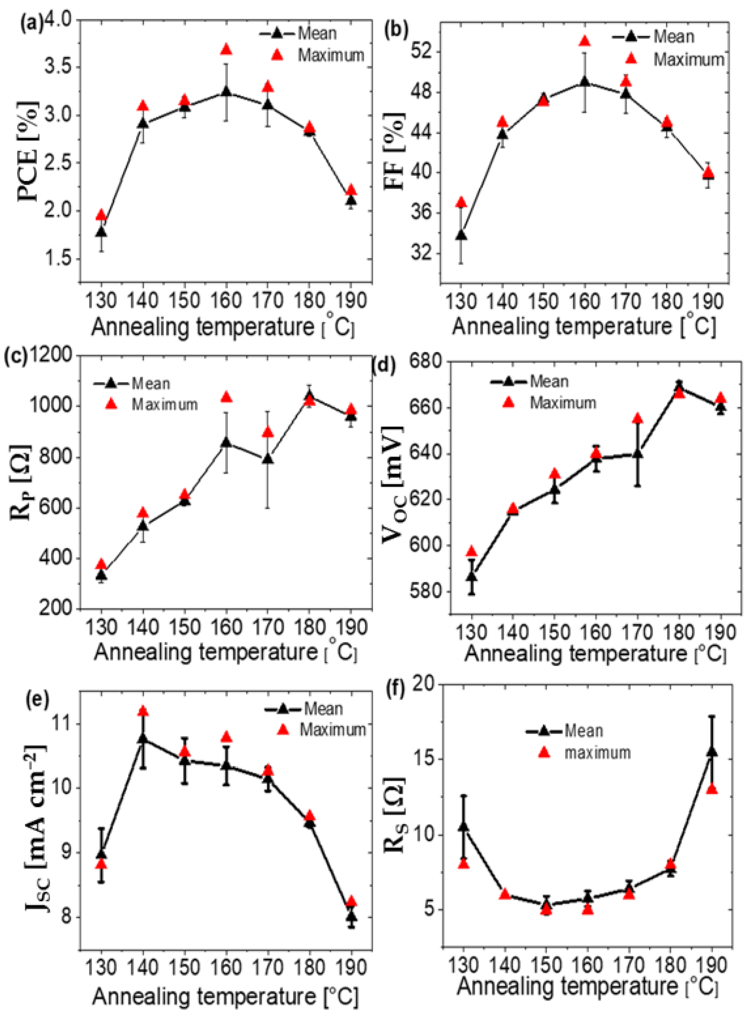
3. Results and Discussion
4. Conclusions
Supplementary Materials
Author Contributions
Funding
Institutional Review Board Statement
Informed Consent Statement
Data Availability Statement
Acknowledgments
Conflicts of Interest
References
- Meng, L.; Zhang, Y.; Wanm, X.; Li, C.; Zhang, X.; Wang, Y.; Ke, X.; Xiao, Z.; Ding, L.; Xia, R.; et al. Organic and solution-processed tandem solar cells with 17.3% efficiency. Science 2018, 361, 1094–1098. [Google Scholar] [CrossRef] [Green Version]
- Jia, Z.; Qin, S.; Meng, L.; Ma, Q.; Angunawela, I.; Zhang, J.; Li, X.; He, Y.; Lai, W.; Li, N.; et al. High performance tandem organic solar cells via a strongly infrared-absorbing narrow bandgap acceptor. Nat. Commun. 2021, 12, 178. [Google Scholar] [CrossRef]
- Jiang, K.; Zhang, J.; Peng, Z.; Lin, F.; Wu, S.; Li, Z.; Chen, Y.; Yan, H.; Ade, H.; Zhu, Z.; et al. Pseudo-bilayer architecture enables high-performance organic solar cells with enhanced exciton diffusion length. Nat. Commun. 2021, 12, 468. [Google Scholar] [CrossRef]
- Almohammedi, A.; Khan, M.T.; Benghanem, M.; Aboud, S.W.; Shkir, M.; AlFaify, S. Elucidating the impact of PbI2 on photophysical and electrical properties of poly (3-hexythiophene). Mater. Sci. Semicond. Process. 2020, 120, 105272. [Google Scholar] [CrossRef]
- Ye, L.; Weng, K.; Xu, J.; Du, X.; Chandrabose, S.; Chen, K.; Zhou, J.; Han, G.; Tan, S.; Xie, Z.; et al. Unraveling the influence of non-fullerene acceptor molecular packing on photovoltaic performance of organic solar cells. Nat. Commun. 2020, 11, 6005. [Google Scholar] [CrossRef]
- McNeill, C.R.; Halls, J.J.M.; Wilson, R.; Whiting, G.L.; Berkebile, S.; Ramsey, M.G.; Friend, R.H.; Greenham, N.C. Efficient polythiophene/polyfluorene copolymer. bulk heterojunction photovoltaic devices: Device physics and annealing effects. Adv. Funct. Mater. 2008, 18, 182309–182321. [Google Scholar] [CrossRef]
- Savenije, T.J.; Kroeze, J.E.; Yang, X.; Loos, J. The formation of crystalline P3HT fibrils upon annealing of a PCBM:P3HT bulk heterojunction. Thin Solid Film 2006, 511–512, 2–6. [Google Scholar] [CrossRef]
- Abada, Z.; Mellit, A.; Benghanem, M. Influence of blend composition and annealing temperature on optical properties of organic photovoltaic cell based on P3HT: PCBM interpenetrating blend. Int. J. Green Energy 2020, 17, 101–113. [Google Scholar] [CrossRef]
- Zhao, G.; He, Y.; Li, Y. 6.5% Efficiency of polymer solar cells based on poly(3-hexylthiophene) and indene-C60 bisadduct by device optimization. Adv. Mater. 2010, 22, 4355–4358. [Google Scholar] [CrossRef]
- Chen, D.; Nakahara, A.; Wei, D.; Nordlund, D.; Russell, T.P. P3HT/PCBM bulk heterojunction organic photovoltaics: Correlating efficiency and morphology. Nano Lett. 2011, 11, 561–567. [Google Scholar] [CrossRef]
- Green, M.A.; Emery, K.; Hishikawa, Y.; Warta, W.; Dunlop, E.D. Solar cell efficiency tables (version 46). Prog. Photovolt. 2015, 23, 1–7. [Google Scholar] [CrossRef]
- Reyes-Reyes, M.; Kim, K.; Carroll, D.L. High-efficiency photovoltaic devices based on annealed poly(3-hexylthiophene) and 1-(3-methoxycarbonyl)-propyl-1-phenyl-(6,6)C61 blends. Appl. Phys. Lett. 2005, 87, 083506. [Google Scholar] [CrossRef]
- Li, G.; Shrotriya, V.; Yao, Y.; Yang, Y. Investigation of annealing effects and film thickness dependence of polymer solar cells based on poly(3-hexylthiophene). J. Appl. Phys. 2005, 98, 043704. [Google Scholar] [CrossRef] [Green Version]
- Erb, T.; Zhoukhavets, U.; Gobsch, G.; Raleva, S.; Steuhn, B.; Schilinsky, P.; Waldauf, C.; Brabec, C.J. Correlation between structural and optical properties of composite polymer/fullerene films for organic solar cells. Adv. Funct. Mater. 2005, 15, 1193–1196. [Google Scholar] [CrossRef]
- Madogni, V.I.; Kounouhéwa, B.; Akpo, A.; Agbomahéna, M.; Hounkpatin, S.A.; Awanou, C.N. Comparison of degradation mechanisms in organic photovoltaic devices upon exposure to a temperate and a subequatorial climate. Chem. Phys. Lett. 2015, 640, 201–214. [Google Scholar] [CrossRef] [Green Version]
- Jørgensen, M.; Norrman, K.; Gevorgyan, S.A.; Tromholt, T.; Andreasen, B.; Krebs, F.C. Stability of Polymer Solar Cells. Adv. Mater. 2012, 24, 580–612. [Google Scholar] [CrossRef] [PubMed]
- Manceau, M.; Rivaton, A.; Gardette, J.L.; Guillerez, S.; Lemaitre, N. Light induced degradation of the P3HT-based solar cells active layer. Sol. Energy Mater. Sol. Cells 2011, 95, 1315–1325. [Google Scholar] [CrossRef]
- Glen, T.S.; Scarratt, N.W.; Yi, H.; Iraqi, A.; Wang, T.; Kingsley, J.; Buckley, A.R.; Lidzey, D.G.; Donald, A.M. Grain size dependence of degradation of aluminum/calcium cathodes in organic solar cells following exposure to humid air. Sol. Energy Mater. Sol. Cells 2015, 140, 25–32. [Google Scholar] [CrossRef] [Green Version]
- Turkovic, V.; Engmann, S.; Egbe, D.A.M.; Himmerlich, M.; Krischok, S.; Gobsch, G.; Hoppe, H. Multiple stress degradation analysis of the active layer in organic photovoltaics. Sol. Energy Mater. Sol. Cells 2014, 120, 654–668. [Google Scholar] [CrossRef]
- Hou, X.; Wang, Y.; Lee, H.K.H.; Datt, R.; Miano, N.U.; Yan, D.; Li, M.; Zhu, F.; Hou, B.; Tsoi, W.C.; et al. Indoor application of emerging photovoltaics—Progress, challenges and perspectives. J. Mater. Chem. A 2020, 8, 21503–21525. [Google Scholar] [CrossRef]
- Lin, C.; Lin, E.Y.; Tsai, F.Y. Enhanced thermal stability and efficiency of polymer bulk-heterojunction solar cells by low-temperature drying of the active layer. Adv. Funct. Mater. 2010, 20, 834–839. [Google Scholar] [CrossRef]
- Reese, M.O.; Nardes, A.M.; Rupert, B.L.; Larsen, R.E.; Olson, D.C.; Lloyd, M.T.; Shaheen, S.E.; Ginley, D.S.; Rumbles, G.; Kopidakis, N. Photoinduced degradation of polymer and polymer–fullerene active layers: Experiment and theory. Adv. Funct. Mater. 2010, 20, 3476–3483. [Google Scholar] [CrossRef]
- Jørgensen, M.; Norrman, K.; Krebs, F.C. Stability/degradation of polymer solar cells. Sol. Energy Mater. Sol. Cells 2008, 92, 686–714. [Google Scholar] [CrossRef]
- Mihailetchi, V.D.; Koster, L.J.A.; Blom, P.W.M.; Melzer, C.; de Boer, B.; van Duren, J.K.J.; Janssen, R.A.J. Compositional dependence of the performance of poly(p-phenylene vinylene): Methanofullerene bulk-heterojunction solar cells. Adv. Funct. Mater. 2005, 15, 795–801. [Google Scholar] [CrossRef] [Green Version]
- Padinger, F.; Rittberger, R.S.; Sariciftci, N.S. Effects of postproduction treatment on plastic solar cells. Adv. Funct. Mater. 2003, 13, 85–88. [Google Scholar] [CrossRef]
- Schilinsky, P.; Waldauf, C.; Brabec, C.J. Recombination and loss analysis in polythiophene based bulk heterojunction photodetectors. Appl. Phys. Lett. 2002, 81, 3885–3887. [Google Scholar] [CrossRef]
- Huang, J.; Li, G.; Yang, Y. Influence of composition and heat-treatment on the charge transport properties of poly(3-hexylthiophene) and [6,6]-phenyl C61-butyric acid methyl ester blends. Appl. Phys. Lett. 2005, 87, 112105. [Google Scholar] [CrossRef] [Green Version]
- Li, G.; Shrotriya, V.; Huang, J.; Yao, Y.; Moriarty, T.; Emery, K.; Yang, Y. High-efficiency solution processable polymer photovoltaic cells by self-organization of polymer blends. Nat. Mater. 2005, 4, 864–868. [Google Scholar] [CrossRef]
- Supriyanto, A.; Mustaqim, A.; Agustin, M.; Ramelan, A.H.; Rosa, E.S.; Nurosyid, F. Fabrication of organic solar cells with design blend P3HT:PCBM variation of mass ratio. Ser. Mater. Sci. Eng. 2016, 107, 012050. [Google Scholar]
- Chi, D.; Qu, S.; Wang, Z.; Wang, J. High efficiency P3HT:PCBM solar cells with an inserted PCBM layer. J. Mater. Chem. C 2014, 2, 4383. [Google Scholar] [CrossRef]
- Chang, S.C.; Hsiao, Y.J.; Li, T.S. P3HT:PCBM incorporated with silicon nanoparticles as photoactive layer in efficient organic photovoltaic devices. L Nanomater. 2013, 2013, 1–4. [Google Scholar] [CrossRef]
- Khairulaman, F.L.; Yap, C.C.; Jumali, M.H. Improved performance of inverted type organic solar cell using copper iodide-doped P3HT:PCBM as active layer for low light application. Mater. Lett. 2021, 283, 128827. [Google Scholar] [CrossRef]
- Yaacobi-Gross, N.; Treat, N.D.; Pattanasattayavong, P.; Faber, H.; Perumal, A.K.; Stingelin, N.; Bradley, D.D.C.; Stavrinou, P.N. High-efficiency organic photovoltaic cells based on the solution-processable hole transporting interlayer copper thiocyanate (CuSCN) as a replacement for PEDOT:PSS. Adv. Energy Mater. 2015, 5, 1401529. [Google Scholar] [CrossRef] [Green Version]
- Alam, S.; Meitzner, R.; Kaestner, C.; Ulbricht, C.; Hoeppener, S.; Egbe, D.A.M.; Schubert, U.S.; Hoppe, H. Controlling donor crystallinity and phase separation in bulk heterojunction solar cells by the introduction of orthogonal solvent additives. MRS Adv. 2018, 3, 1891–1900. [Google Scholar] [CrossRef] [Green Version]
- Yu, R.; Yao, H.; Cui, Y.; Hong, L.; He, C.; Hou, J. Improved charge transport and reduced nonradiative energy loss enable over 16% efficiency in ternary polymer solar cells. Adv. Mater. 2019, 31, 1902302. [Google Scholar] [CrossRef]
- Liu, Y.; Zhang, J.; Zhou, G.; Liu, F.; Zhu, X.; Zhang, F. Electric field facilitating hole transfer in non-fullerene organic solar Cells with a negative HOMO offset. J. Phys. Chem. C 2020, 124, 15132–15139. [Google Scholar] [CrossRef]
- Saeed, M.A.; Kim, S.H.; Kim, H.; Liang, J.; Woo, H.Y.; Kim, T.G.; Yan, H.; Shim, J.W. Indoor organic photovoltaics: Optimal cell design principles with synergistic parasitic resistance and optical modulation effect. Adv. Energy Mater. 2021, 2003103. [Google Scholar] [CrossRef]
- Goo, J.S.; Lee, J.H.; Shin, S.C.; Park, J.S.; Shim, J.W. Undoped ZnO electrodes for low-cost indoor organic photovoltaics. Mater. Chem. A 2018, 6, 23464. [Google Scholar] [CrossRef]


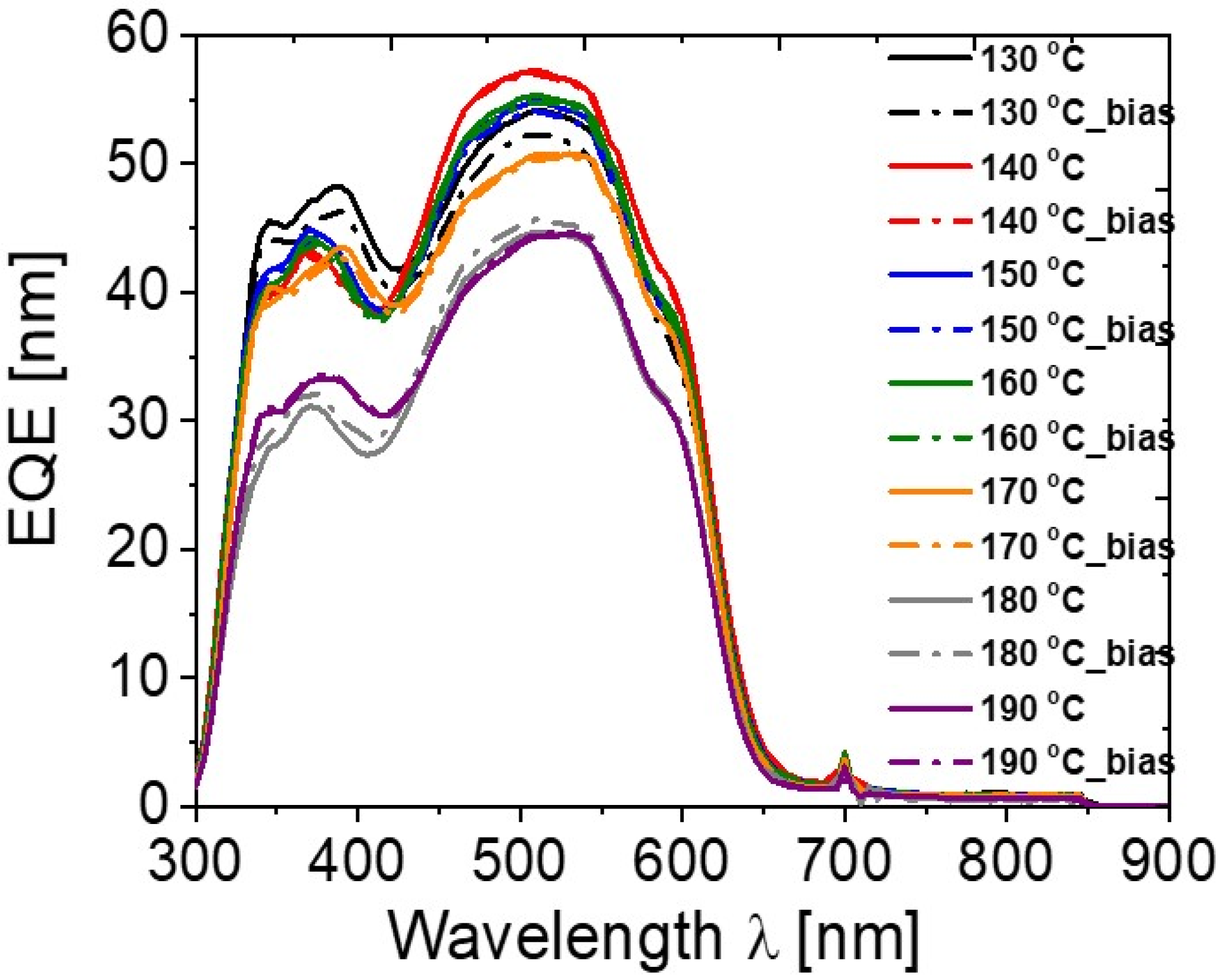
| Annealing Temperature (°C) | JSC (mA/cm2) | VOC (mV) | FF (%) | PCE (%) | RS (Ω) | RP (Ω) | Area (cm2) | Pmax (mW) | Vm (mV) | Jm (mA/cm2) |
|---|---|---|---|---|---|---|---|---|---|---|
| 130 | 8.82 | 597 | 37 | 1.95 | 8 | 376 | 0.42 | 0.82 | 360 | 5.43 |
| 140 | 11.17 | 616 | 45 | 3.09 | 6 | 579 | 0.42 | 1.3 | 400 | 7.74 |
| 150 | 10.56 | 631 | 47 | 3.15 | 5 | 651 | 0.42 | 1.32 | 430 | 7.32 |
| 160 | 10.78 | 640 | 53 | 3.68 | 5 | 1035 | 0.42 | 1.54 | 460 | 8 |
| 170 | 10.26 | 655 | 49 | 3.29 | 6 | 897 | 0.42 | 1.38 | 450 | 7.32 |
| 180 | 9.46 | 669 | 45 | 2.85 | 8 | 1055 | 0.42 | 1.2 | 420 | 6.79 |
| 190 | 8.24 | 664 | 40 | 2.21 | 13 | 987 | 0.42 | 0.93 | 390 | 5.67 |
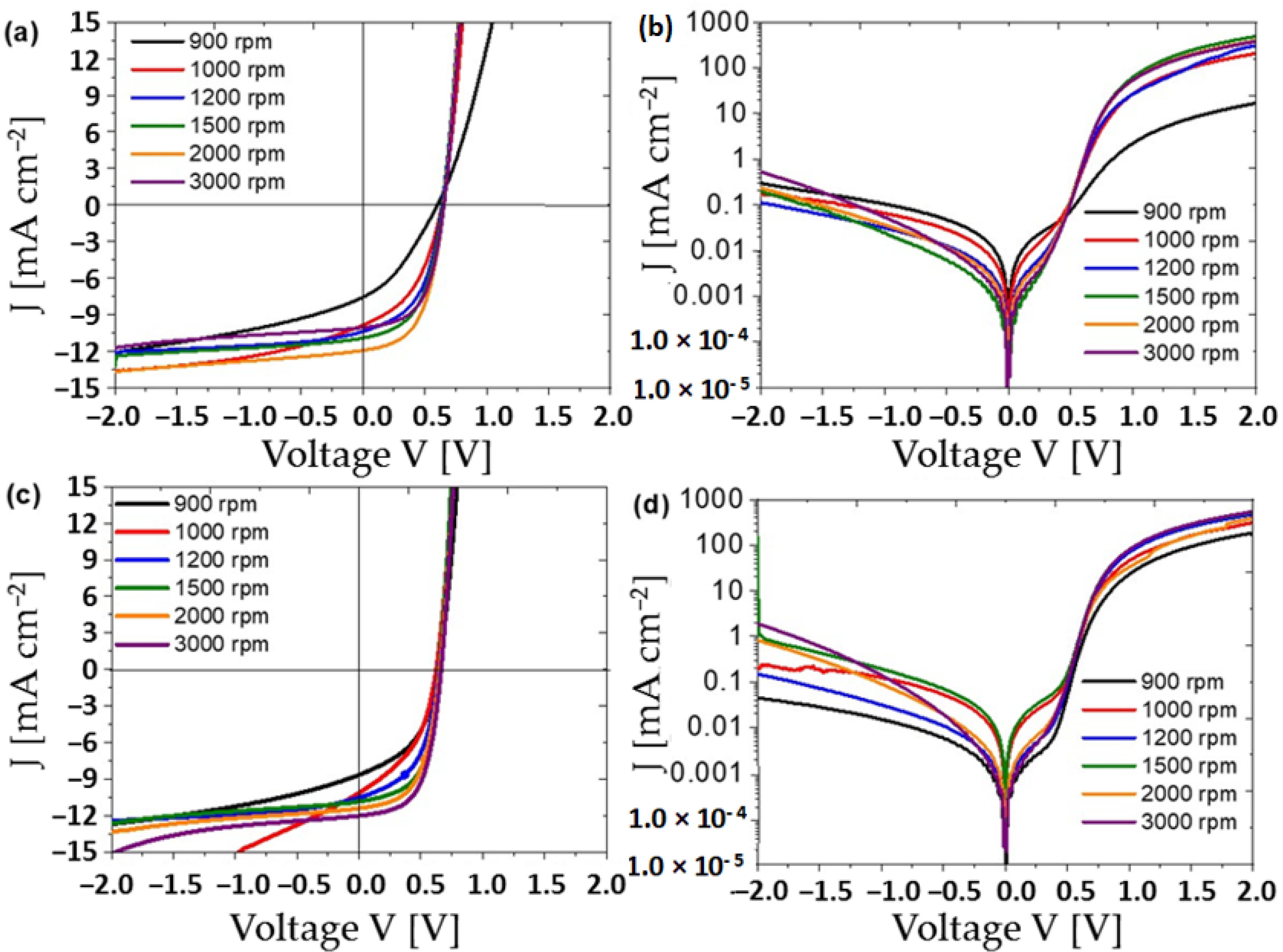
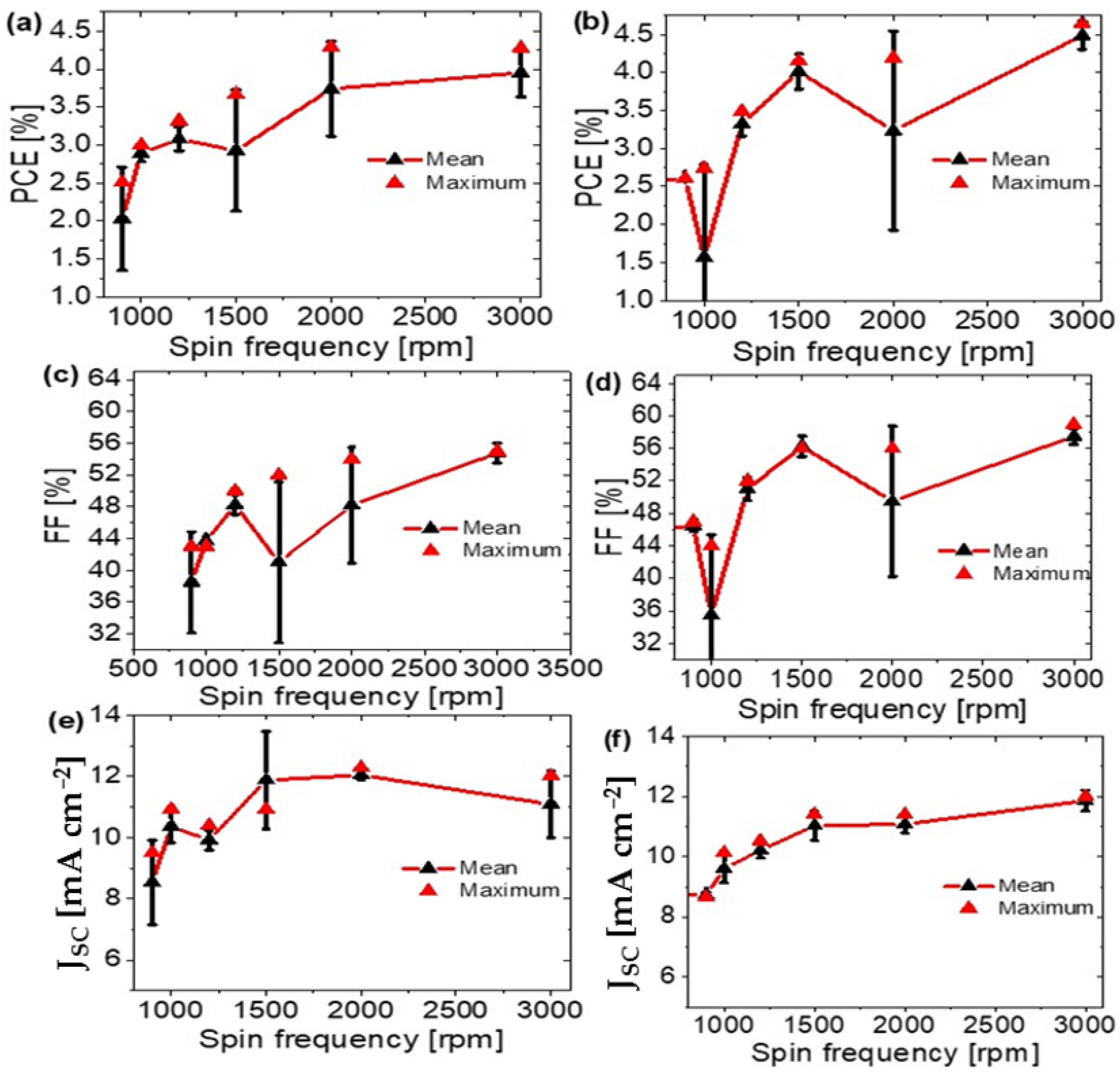
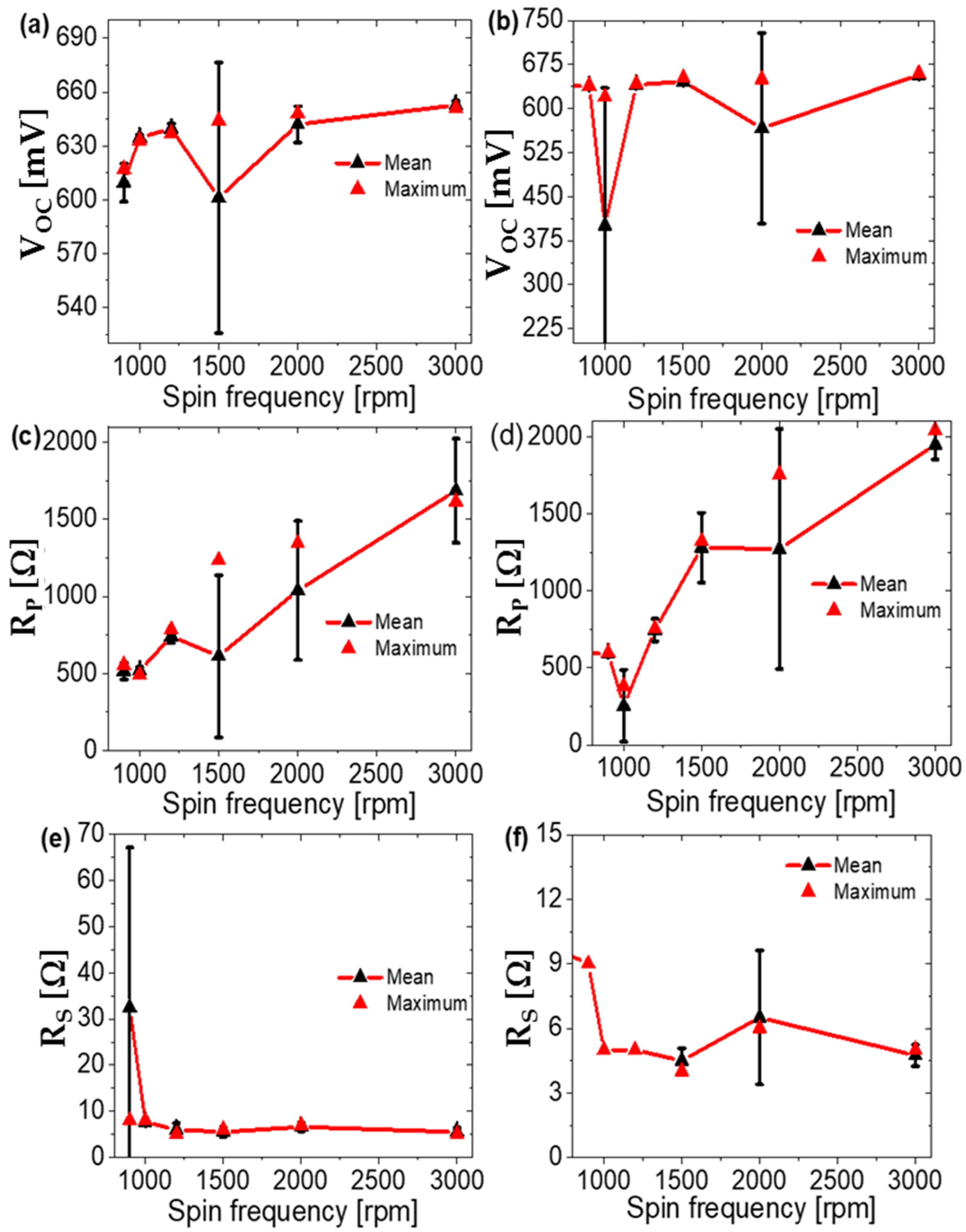
| Spin Frequency (rpm) | Cathode | JSC (mA/cm2) | VOC (mV) | FF (%) | PCE (%) | RS (Ω) | RP (Ω) | Pmax (mW) | Vm (mV) | Jm (mA/cm2) |
|---|---|---|---|---|---|---|---|---|---|---|
| 900 | Mg-Al | 8.649 | 639 | 47 | 2.61 | 9 | 599 | 1.1 | 450 | 5.80 |
| 1000 | Mg-Al | 10.138 | 620 | 44 | 2.74 | 5 | 380 | 1.15 | 430 | 6.38 |
| 1200 | Mg-Al | 10.524 | 642 | 52 | 3.49 | 5 | 754 | 1.47 | 460 | 7.59 |
| 1500 | Mg-Al | 10.844 | 646 | 58 | 4.09 | 4 | 1562 | 1.72 | 480 | 8.52 |
| 2000 | Mg-Al | 11.408 | 650 | 56 | 4.19 | 6 | 1755 | 1.76 | 470 | 8.91 |
| 3000 | Mg-Al | 12.01 | 660 | 59 | 4.65 | 5 | 2041 | 1.95 | 480 | 9.70 |
| 900 | Al | 7.571 | 602 | 34 | 1.55 | 5.7 | 477 | 0.65 | 330 | 4.71 |
| 1000 | Al | 9.872 | 636 | 44 | 2.78 | 8 | 536 | 1.17 | 410 | 6.79 |
| 1200 | Al | 10.397 | 637 | 50 | 3.32 | 5 | 784 | 1.39 | 450 | 7.37 |
| 1500 | Al | 10.929 | 644 | 52 | 3.67 | 6 | 1235 | 1.54 | 450 | 8.15 |
| 2000 | Al | 11.944 | 653 | 54 | 4.21 | 6 | 1591 | 1.77 | 460 | 9.15 |
| 3000 | Al | 10.08 | 653 | 56 | 3.71 | 7 | 2139 | 1.56 | 470 | 7.89 |
Publisher’s Note: MDPI stays neutral with regard to jurisdictional claims in published maps and institutional affiliations. |
© 2021 by the authors. Licensee MDPI, Basel, Switzerland. This article is an open access article distributed under the terms and conditions of the Creative Commons Attribution (CC BY) license (https://creativecommons.org/licenses/by/4.0/).
Share and Cite
Shaban, M.; Benghanem, M.; Almohammedi, A.; Rabia, M. Optimization of the Active Layer P3HT:PCBM for Organic Solar Cell. Coatings 2021, 11, 863. https://doi.org/10.3390/coatings11070863
Shaban M, Benghanem M, Almohammedi A, Rabia M. Optimization of the Active Layer P3HT:PCBM for Organic Solar Cell. Coatings. 2021; 11(7):863. https://doi.org/10.3390/coatings11070863
Chicago/Turabian StyleShaban, Mohamed, Mohamed Benghanem, Abdullah Almohammedi, and Mohamed Rabia. 2021. "Optimization of the Active Layer P3HT:PCBM for Organic Solar Cell" Coatings 11, no. 7: 863. https://doi.org/10.3390/coatings11070863