Article

Investigation of the Anti-Corrosion Properties of Fluorinated Graphene-Modified Waterborne Epoxy Coatings for Carbon Steel

1
College of Materials Science and Engineering, Sichuan University of Science and Engineering, Zigong 643000, China
2
Zhongshan Photoelectric Material Co., Ltd., Zibo 255138, China
3
Material Corrosion and Protection Key Laboratory of Sichuan Province, Sichuan University of Science and Engineering, Zigong 643000, China
4
Chimie ParisTech, PSL Research University, CNRS, Institut de Recherche de Chimie Paris (IRCP), 75005 Paris, France
*
Authors to whom correspondence should be addressed.
Coatings 2021, 11(2), 254; https://doi.org/10.3390/coatings11020254
Submission received: 16 January 2021 / Revised: 12 February 2021 / Accepted: 19 February 2021 / Published: 21 February 2021
(This article belongs to the Special Issue Modern Trends in Corrosion Protection of Steels)

Abstract

:
Waterborne epoxy resin (WEP) has been widely used as an anti-corrosive coating for metals. However, it is still a big challenge to further improve its anti-corrosion performance due to the poor barrier properties to corrosive media. In this study, fluorinated graphene (FG) was used as a filler in WEP to improve its barrier properties, which contributes to corrosion resistance enhancement. The chemical composition and microstructures of FG and FG-modified WEP were systematically analyzed, and its corrosion resistance was also studied. Results reveal that the addition of FG sheet to WEP not only can significantly improve the tensile strength of WEP coating, but also increase the barrier properties of WEP coating and block the penetration of corrosive agent throughout the coating to the interface between coating and substrate. Meanwhile, the results also declare that the F content of FG has a significant effect on mechanical properties and long-term corrosion resistance, and the performance of FG-modified WEP coating will deteriorate with the increase of F content.

1. Introduction

Corrosion commonly appears in our daily life, and may give rise to tremendous economic losses and many potential safety problems [1]. Epoxy resins (EP) are widely used as heavy-duty anticorrosion coatings because of their excellent properties, such as chemical resistance, toughness, low shrinkage on cure, mechanical, corrosion resistance and excellent adhesion on various substrates [2,3,4]. Recently, more attention has been paid to the waterborne epoxy resins (WEP) due to the increased legislative restrictions on the emission of organic solvents into the atmosphere [5]. However, it is a big challenge for WEP coating to achieve ideal corrosion resistance due to its poor barrier properties to corrosive media, such as oxygen, water, and chloride ions [6]. Therefore, researchers applied numerous measures to enhance the barrier performance and corrosion protection properties of waterborne coatings. Particularly, nanofillers addition has been studied extensively, such as ZnO [7], TiO2 [8], ZrO2 [9] and PANi [10].
Graphene, which has high mechanical strength, high thermal conductivity, high surface area and a very dense network, is an important 2D lamellar structure material [11,12,13]. In recent years, graphene has been widely investigated as coatings to prevent thermal oxidation [14], chemical oxidation [15,16] and electrochemical corrosion [17,18,19]. However, Dong et al. [20] found that graphene coating retained its protection property only for a short period of time, and graphene can promote metal corrosion at coating defects during the long-term immersion. Zhou et al. [21] also found the graphene-induced corrosion promotion phenomenon of copper. They believed that the corrosion promotion effect was caused by the defects and high electrical conductivity of graphene. Therefore, it is necessary to adopt some strategies to reduce the electrical conductivity of graphene. Sun et al. introduced several strategies to inhibit the conductivity of graphene, such as insulating pernigraniline modification [22], silane coupling agent decoration [23] and nanosized silicon oxides isolation [24]. They found that these strategies can effectively reduce the conductivity of graphene and enhance the corrosion resistance of graphene coatings. Moreover, Zheng et al. [25,26] successfully synthesized novel GO-poly(urea-formaldehyde) (GUF) composites by anchoring a prepolymer of urea-formaldehyde (UF) resin onto graphene oxide (GO) sheets through in situ polycondensation. They demonstrated that GUF composites have superior compatibility with epoxy resin and can significantly improve the long-term corrosion resistance of the epoxy coating. Another found is that the conductivity of graphene decreased rapidly after oxidation, but the corrosion resistance of GO-modified EP coating is not ideal due to GO has poor compatibility in epoxy. Moreover, Calovi et al. [27] emphasized the importance of the functionalization processes of graphene oxide and the functionalized graphene oxide concentration to improve their distribution within the polymeric matrix. Based on the above studies, it is not hard to see that the compatibility of modified graphene in matrix resin should be considered as well as the decline in the conductivity of graphene.
Fluorinated graphene (FG) is a novel graphene derivative material. Compared with graphene, FG has low surface energy, high chemical stability, high friction resistance and excellent insulation property due to the C−F covalent bond formed on the surface of graphene with the hybridization mode of carbon atoms changed from sp2 to sp3 [28,29]. Min et al. [30] stated that the addition of FG into lubricating oil can significantly increase the wear resistance and bearing capacity of lubricating oil. Bharathidasan et al. [31] successfully fabricated PDMS-fluorinated graphene oxide composite coating with a contact angle of 173.7°. Yang et al. [32] prepared an FG film on the surface of epoxy coating, which made the surface of epoxy coating have a superhydrophobic function. Although FG has gained attention in the fields of lubrication, superhydrophobic and other fields, the research of FG in the field of anti-corrosion coating is very limited. According to the limited reports [33], FG additive could significantly improve the long-term corrosion resistance of the epoxy coating and the amount of additive is an important factor. However, the intrinsic diversity in the surface morphology, composition and microstructure of FG with different F content may result in quite a different compatibility and stability of FG in WEP, and then affect the performance of FG-modified waterborne epoxy resin coating.
In this paper, FG with different F content and its compatibility in waterborne epoxy resins are studied. Meanwhile, the effect of FG on the improvement of the corrosion resistance of WEP coatings is discussed. This work validated the feasibility of FG in modifying waterborne coatings and proposed a feasible approach for preparing ideal waterborne epoxy resin coating.

2. Materials and Methods

2.1. Materials

Q 235 carbon steel (0.12 C, 0.29 Mn, 0.04 Si, 0.03 S, 0.02 P and balance Fe in mass %) was used as the substrate material. Plate samples were grit-blasted to remove the oxide skin and cleaned with ethanol by ultrasound cleaning.
The fluorinated graphene (FG) nanosheets with different F content (19.7%, 29.0%, and 48.3% in mass %) were obtained from Zhongshan Photoelectric Material Co. Ltd. (Zibo, Shandong, China). The thickness of the three FG nanosheets was approximately 1.5–3.0 nm. As the thickness of a single layer FG is 0.8–1.0 nm [33], the layer number of the three FG nanosheets was approximately 2–4. Waterborne epoxy system is a two-component commercial waterborne resin. Waterborne epoxy resin (WEP) and curing agent purchased from Kester (Shenzhen, Guangdong, China), without corrosion inhibitor. WEP (solid content: 89–91%, proportion: 1.05–1.10 g·m−3 and epoxy equivalent: 190–200 g·mol−1) is based on modified epoxy resin and curing agent is based on modified polyamide. All materials were used as received and without further purification.

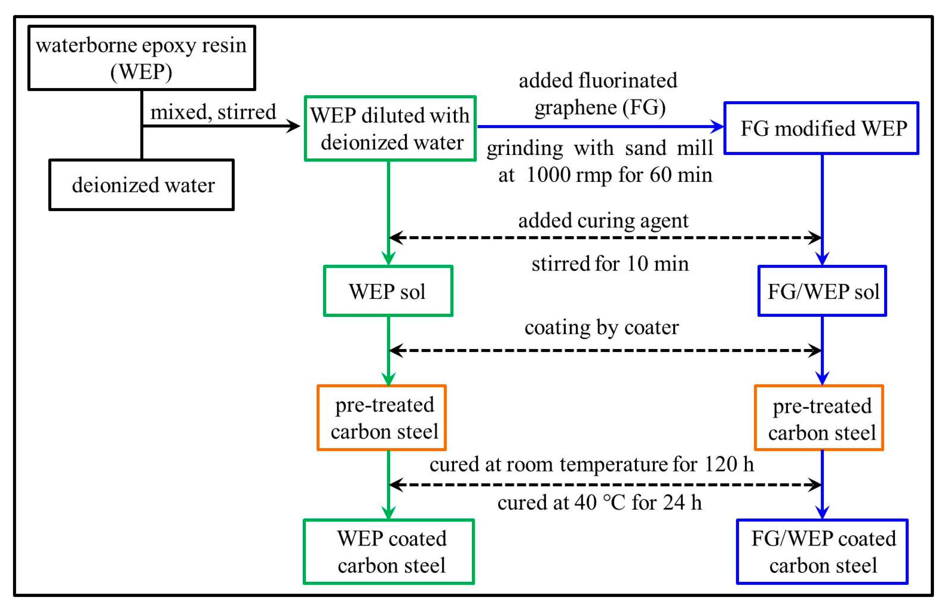
2.2. Preparation of the Coatings

Firstly, waterborne epoxy resin and deionized water were mixed according to a weight ratio of 10:1. Then, fluorinated graphene with different F content (19.7%, 29.0%, and 48.3%) was added to the above waterborne epoxy resin, respectively. The filler concentration of the three FG was 0.3 wt.% of the waterborne epoxy resin. The mixtures were stirred and dispersed by grinding with sand mill at speed of 1000 rpm for 60 min at 25 °C. Waterborne curing agent (with WEP to curing agent weight ratio of 2:1) was added to the resin mixture, and mechanically stirred for 10 min to obtain a uniform mixture. Finally, the mixture was applied to the surface of pre-treated carbon steel panels and the thickness of the coatings was controlled by a coater. The specimens were subsequently cured at room temperature for 120 h and then in a drying oven at 40 °C for 24 h. The thickness of the dried coating was 120 ± 10 μm. The schematic diagram of the coating preparation process is shown in Figure 1.

2.3. Characterization

The crystalline structure of fluorinated graphene was investigated by X-ray diffraction (XRD, D8 ADVANCE, BRUKER, Ettlingen, Germany) with Cu-Kα radiation (λ = 0.15406 nm). The chemical changes of the functional groups were studied by Fourier transform infrared (FT-IR, NICOLET 6700, Thermo, Waltham, MA, USA) spectroscopy. The morphology of the FG sheets and FG/WEP composites were characterized by scanning electron microscopy (SEM, S4800, Hitachi, Tokyo, Japan), and the samples were pre-treated by gold sputtering.
The dispersion of FG in WEP was characterized by sedimentation test, the FG-modified WEP mixtures were added in NEG glass and exposed to collimated incandescent light. The tensile stress–strain characteristics of FG/WEP composites were studied by an electromechanical universal testing machine (CMT8502, Shenzhen SANS Testing Machine Co. Ltd., Shenzhen, China) with an operating head load of 5 KN and a testing speed of 10 mm·min−1. The samples were prepared as cast with a size of 1 mm × 15 mm × 250 mm in a mold according to ASTM D3039 [3]. Each test was repeated three times to ensure repeatability. Adhesion strength was determined by PosiTest AT-A (DeFelsko Corporation, New York City, NY, USA). The adhesion measurements were performed at ambient temperature before and after immersion in 3.5 wt.% NaCl solution for 5000 h. Prior to each measurement, the coatings were removed from the test solution, rinsed with deionized water and dried in air for 5 days. Five coatings of each series were measured to obtain the average adhesion strength value.
Electrochemical impedance spectroscopy (EIS) was used to evaluate the corrosion resistance of the coatings by an electrochemical workstation (Auto-lab, PGSTAT302, Herisau, Switzerland) with a conventional three-electrode cell, with a platinum plate as the counter electrode, a saturated calomel electrode (SCE) as the reference electrode, and the coated carbon steel as the working electrode. These tests were performed at frequencies ranging from 100 kHz to 10 mHz by using a 20 mV amplitude sinusoidal voltage at open circuit potential (OCP) in 3.5 wt.% NaCl solution, and the experimental data were analyzed by using ZsimpWin software [25]. The EIS measurements were carried out 3 times to ensure the repeatability of the measurements.

3. Results and Discussion

3.1. Characterization of FG

The surface morphology, XRD patterns and FT-IR spectra of FG with different F content are shown in Figure 2. As shown in Figure 2a,c, the graphene flakes with a low F content are highly agglomerated powders with some crumpling structures of the exfoliated. The size of the flakes ranges from submicron to several microns. The edges of the fluorinated graphene particles are uneven, and the layers are slightly separated into loose shapes. However, as the F content reaches 48.3%, there are some smaller graphene nanosheets in the microscopic morphology size and have an amorphous thin layered structure, which may be caused by the high content of fluorine.
Figure 2d shows three diffraction peaks around 12.8°, 26.7° and 41.0°, which can be assigned to the (001), (002), and (100) crystal planes, respectively. The (001) diffraction peak of 48.3% FG is significantly higher than that of 19.7% FG and 29.0% FG, suggesting that the crystal structure of FG is largely dependent on F content [34]. Meanwhile, the (002) crystal plane is related to the six structures of graphite, and the stronger the diffraction peak is, the more difficult graphene fluorinated. As shown in Figure 2d, the (002) diffraction peak of fluorinated graphene become to weaken and broaden as the F content increase from 19.7% to 48.3%, indicating that the graphene with a high F content is more disordered in the stacking direction and contains more free-stacked lamellar structures [35]. Moreover, the (100) diffraction peak of FG is also caused by fluorination.
The FT-IR spectra of fluorinated graphene with different F content are shown in Figure 2e. Generally, the stretching vibrations of the C−F covalent bonds at 1225 cm−1 and asymmetric stretching vibrations of CF2 groups at 1328 cm−1 are used to identify the existence of F element in FG [36]. From Figure 2e, the intensity of the diffraction peak at 1225 cm−1 gradually increases with the increase of F content, indicating that the number of C−F covalent bonds gradually increases which is conducive to a decrease in the surface energy of FG. Moreover, the peak appears at 1540 cm−1 and 1642 cm−1 are attributed to carbon skeletons, and the intensity of these diffraction peaks has significant decrease as the F content increase to 48.3%. This phenomenon can be explained by the C−F covalent bond formed on the surface of graphene with the hybridization mode of carbon atoms changed from sp2 to sp3 [28,29]. In addition, the peak at 3436 cm−1 is ascribed to the O−H stretches. These peaks suggest that FG contains a hydrophilic group, which is expected to have better compatibility with polar materials.
Based on the above results, the diversity in surface morphology, composition and microstructure of the FG with different F content may result in quite a different compatibility and stability in WEP, which might significantly affect the mechanical properties and corrosion resistance of WEP coating.

3.2. Characterization of FG/WEP

A sedimentation test was employed to determine the compatibility and stability of FG in WEP. Figure 3a,c show the visual illustration of FG dispersed in WEP at different times. It can be seen that FG with different F content has a uniform dispersion in WEP in the initial stage. However, 48.3% FG/WEP has obvious delamination after 1000 h and there is an amount of FG deposited on the bottom of the bottle in the observation up to 2000 h. In contrast, 19.7% FG and 29.0% FG are relatively uniformly dispersed in WEP. The reason for this phenomenon can be attributed to the number of C−F bonds in FG increases and the surface energy of FG decreases cause the reduction of the compatibility of FG in WEP with the increasing of F content of FG.
SEM of the cross-sectional microstructure characteristics of WEP and FG/WEP coatings are shown in Figure 3d,f. From the SEM results, the fracture surface of the WEP coating is smooth and flat, which is a typical brittle fracture [37]. By comparison, the fracture surface of WEP coatings with FG sheets is rough and uneven, suggesting that the fracture mode of WEP coating changes from brittleness to toughness. Moreover, there are some cracks scattered in 48.3% FG/WEP coating which cannot be detected in 19.7% FG/WEP coating and 29.0% FG/WEP coating. This demonstrates that FG with a high F content has bad compatibility in WEP.
Graphene nanoplates are short stacks of individual layers of graphite that often increase the tensile modulus of composite material [38]. Figure 3h shows stress–strain curves of different FG-modified WEP. As illustrated in this figure, the tensile modulus of WEP improves after adding different FG, which is similar to the former report about graphene nanoplates [38]. Moreover, the tensile strength of WEP coating increases from 30 MPa to 68 MPa via adding 29.0% FG. In addition, it can be seen that the tensile strength of WEP coating first increases and then decreases with the increase of F content of FG. This phenomenon can be attributed to the decrease of compatibility between 48.3% FG and WEP as shown in Figure 3g. This indicates that the addition of FG is beneficial to improve the mechanical properties of WEP and also reflects the different compatibility between WEP and FG with different F content.
As suggested above, FG with different F content has a different surface morphology, composition and microstructure, which will affect the interface between FG and waterborne epoxy resin and the penetration of corrosive medium in the coating. Then, the effects of FG on the effectiveness of anti-corrosion performances of WEP coating are further studied.

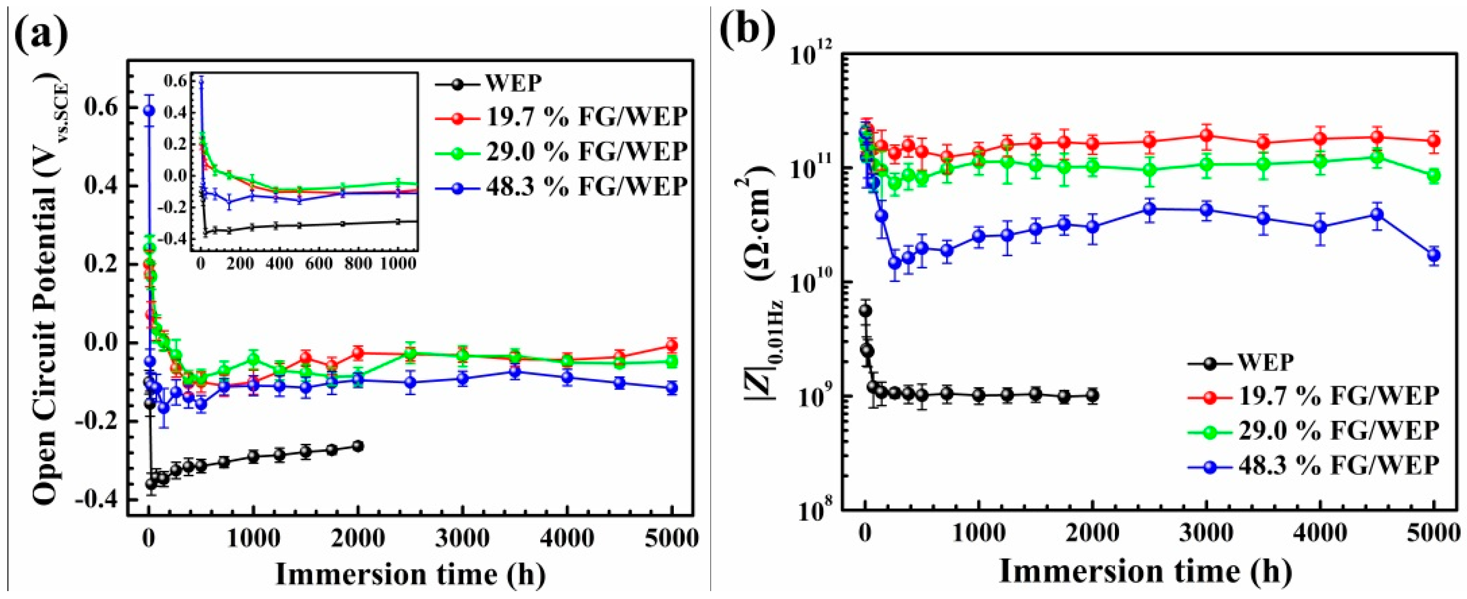
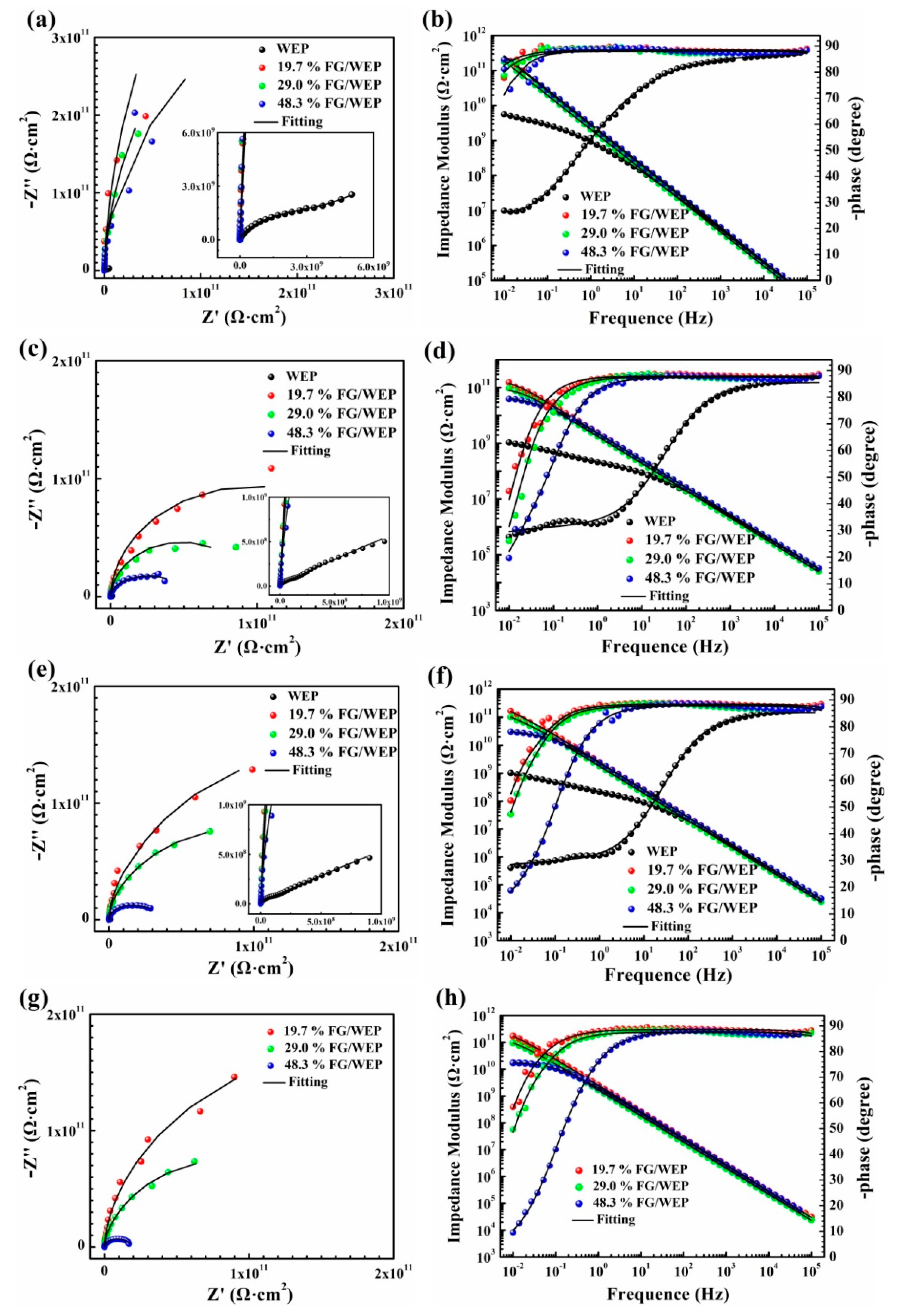
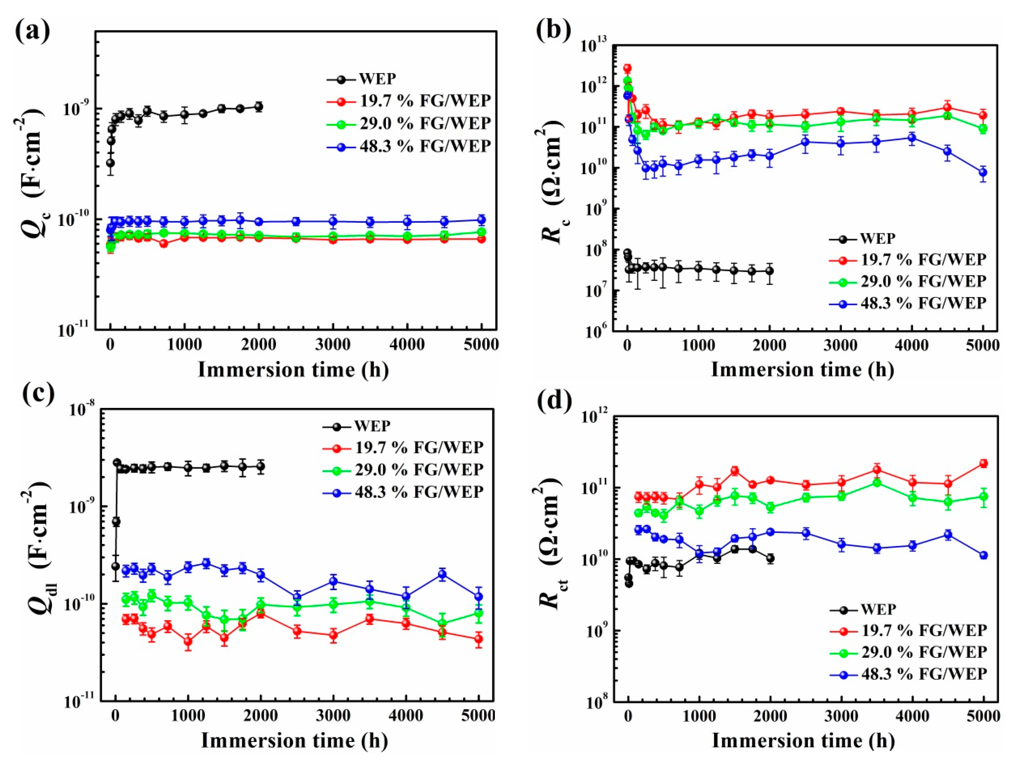
3.3. Anti-Corrosion Performance of the Coatings

EIS was employed to evaluate the corrosion resistance and analyze the anticorrosion mechanism of WEP and FG-modified WEP coatings on carbon steel during long-term immersion in 3.5 wt.% NaCl solution.
The OCP values of various samples immersed in 3.5 wt.% NaCl solution were investigated at different periods. As shown in Figure 4a, the OCP of WEP coating decreased from −0.101 V vs. SCE at 3 h to −0.360 V vs. SCE at 24 h. OCP of 48.3% FG/WEP coating decreased from 0.592 V vs. SCE at 24 h to −0.166 V vs. SCE at 144 h. This result may be attributed to permeation by water before 24 and 144 h in WEP and 48.3% FG/WEP coatings, respectively. Meanwhile, the OCP of FG/WEP coatings was higher than that of WEP coating; this result suggests the FG/WEP coating/metal interface had a lower risk of corrosion, which means the more remarkable protective performance of FG/WEP coating than WEP coating. That is, the FG sheets can provide a good corrosion protection property to some extent.
The impedance modulus at the frequency of 0.01 Hz (|Z|0.01Hz) is usually used to evaluate the stability and anti-corrosion performance of anti-corrosion coatings on a metal substrate [25,39,40]. |Z|0.01Hz of WEP and FG/WEP coatings as a function of immersion time are presented in Figure 4b. It can be found that the |Z|0.01Hz values of WEP, 19.7% FG/WEP, 29.0% FG/WEP and 48.3% FG/WEP coatings rapidly decreased at the onset of immersion, and then reached a relatively steady value at 9.88 × 10⁸, 1.24 × 10¹¹, 7.32 × 10¹⁰ and 1.47 × 10¹⁰ Ω·cm2, respectively. Moreover, it can be found that the |Z|0.01Hz of WEP and FG/WEP coatings can be arranged as per the following rules: WEP coating < 48.3% FG/WEP coating < 29.0% FG/WEP coating < 19.7% FG/WEP coating throughout the whole immersion period. This demonstrates that the anti-corrosion performance of WEP coating can be significantly improved via doping FG, and the anti-corrosion performance will decrease with the increase of F content.
In order to evaluate the long-term corrosion resistance of WEP and FG/WEP coatings, the EIS data of these four coating/carbon steel systems are presented in Figure 5. Meanwhile, the fitting curves based on the corresponding equivalent circuits (Figure 6) are shown in this figure as well.
According to Figure 5a,b, the Bode and Nyquist plots of three FG/WEP coatings exhibited one-time constants for the early immersion period, suggesting that the corrosive species penetrated into the coating but did not reach the coating/substrate interface at this stage. The EIS data at this stage can be demonstrated by a physical model and its corresponding equivalent circuit shown in Figure 6a. However, a new time constant corresponding to charge transfer of electrochemical corrosion reaction occurs at low frequency for WEP coating. This indicates that the corrosive agent has penetrated the coating and reached the coating/substrate interface, and resulted in the corrosion of the carbon steel. Thus, the equivalent circuit in Figure 6b can be used to fit EIS data of WEP coating.
As the immersion time increased to 140 h, the |Z|0.01Hz values of WEP coating exhibited a downward trend and two-time constants in Figure 5c,d. Therefore, the Model B equivalent circuit Figure 6b was still applied for WEP coating. Meanwhile, it can be found that the phase angle of three FG/WEP coatings at low frequency has reduced to lower than 40°, which indicates that the corrosive agent has penetrated the FG/WEP coatings and reached the coating/substrate interface. Thus, the Model B equivalent circuit Figure 6b can be used to explain and fit the EIS data of FG/WEP coatings after immersion 140 h.
As the immersion time increased to 2000 h and 5000 h, the Bode and Nyquist plots of WEP and FG/WEP coatings had no significant changes as shown in Figure 5e–h. This indicates that the corrosive agent penetrated slowly inside the coating and the corrosion occurred on the surface of carbon steel at a slow rate. Therefore, the EIS data of WEP and FG/WEP coatings should be fitted by Model B equivalent circuit as the immersion time increased from 140 to 5000 h.
As shown in Figure 6, model A is composed of solution resistance (Rs), coating capacitance (Qc), and coating resistance (Rc). In addition to the aforementioned parameters, Model B has the double layer capacitance (Qdl), the charge transfer resistance (Rct). The Nyquist plots of all the samples were fitted with the quivalent circuit model according to the former discussion.
Several important parameters of WEP and FG/WEP coating/steel systems, coating resistance Rc, coating capacitance Qc, charge transfer resistance Rct and double layer capacitance Qdl are obtained from EIS data via equivalent circuit fitting. Their evolution tendency with immersion time is used to analyze the anti-corrosion mechanism of WEP and FG/WEP coatings (shown in Figure 7).
Qc is used to evaluate the water uptake in organic coatings [41]. The coating capacitance would increase when water diffused into the coatings. The variation of the coating capacitance of the WEP coating had two stages during immersion. The first stage involves the diffusion of water into the coating: the value of WEP coating capacitance increased from 3.21 × 10⁻¹⁰ F·cm−2 at 3 h to 8.01 × 10⁻¹⁰ F·cm−2 at 72 h. The next variation of the coating capacitance was reached to the second stage (the saturation state), wherein the coating capacitances reached a relatively steady value of 9.95 × 10⁻¹⁰ F·cm−2. However, the increase of the coating capacitances of the FG/WEP coatings was restricted for the 5000 h of immersion. The Qc value of 19.7% FG/WEP coating, 29.0% FG/WEP coating and 48.3% FG/WEP coating increased from 5.91 × 10⁻¹¹, 5.68 × 10⁻¹¹ and 7.96 × 10⁻¹¹ F·cm−2 at 3 h to 6.95 × 10⁻¹¹, 7.21 × 10⁻¹¹ and 9.42 × 10⁻¹¹ F·cm−2 at 144 h, and then reached a relatively steady value at 6.76 × 10⁻¹¹, 7.21 × 10⁻¹¹ and 9.55 × 10⁻¹¹ F·cm−2, respectively. The increment of the coating capacitance of WEP coating was 1 order of magnitude higher than that of the FG/WEP coatings, which implies that the FG/WEP coatings adsorbed less water than the WEP coating.
Generally, Rc is used to represent the barrier and shielding effect of coatings on corrosive media. Rc decreasing with immersion time was due to the penetration of corrosive species through the coating micropores or defects [42]. Figure 7b shows that the Rc value of the WEP coating decreased from 8.37 × 10⁷ Ω·cm2 at 3 h to 3.56 × 10⁷ Ω·cm2 at 72 h, and then stabilized at 2.99 × 10⁷ Ω·cm2 after 72 h. The Rc value of 19.7% FG/WEP coating, 29.0% FG/WEP coating and 48.3% FG/WEP coating decreased from 2.72 × 10¹², 1.35 × 10¹² and 5.77 × 10¹¹ Ω·cm2 at 3 h to 1.94 × 10¹¹, 8.24 × 10¹⁰ and 2.64 × 10¹⁰ Ω·cm2 at 144 h, and then reached a relatively steady value at 1.05 × 10¹¹, 6.56 × 10¹⁰ and 7.69 × 10⁹ Ω·cm2, respectively. The results imply that the barrier properties of WEP coating can be improved greatly during long-term immersion due to the doping of FG in the coating can hinder the penetration of corrosive medium and extend the penetration path (Figure 3d,g). At the same time, the Rc results of the four coatings are similar to the rules as |Z|0.01Hz values (Figure 4b): WEP coating < 48.3% FG/WEP coating < 29.0% FG/WEP coating < 19.7% FG/WEP coating throughout the whole immersion period. Therefore, it can be concluded that the addition of FG can improve the corrosion resistance of WEP, and 19.7% FG has the most obvious effect on improving the corrosion resistance of the coating.
Generally, the higher Qdl is, the more disbonded area formed at the interface of coating/metal [43]. As presented in Figure 7c, WEP coating demonstrated a larger disbonded area than that of FG/WEP coatings, which will increase the risk of corrosion occurred on the interface of coating/metal.
Rct, which is inversely proportional to corrosion rate, is a parameter representing the resistance of the electron transfer across the metal surface. The higher Rct is, the more difficult a corrosion reaction occurs, hence the lower corrosion rate [44]. Figure 7d displays the Rct values of WEP and FG/WEP coating/steel systems are plotted as a function of immersion time. It can be found that Rct values of FG/WEP coatings are higher than that of WEP coating during the whole immersion stage. This result can be attributed to the addition of FG sheet in WEP coating blocks the percolation paths of the corrosive agent transportation through the coating to the metal substrate and then reduce electron transfer at the coating/substrate interface. Meanwhile, the Rct values of FG/WEP coatings have a significant difference, the Rct values decreased with the increase of F content in FG. Thus, the F content of FG acts as an important role in the enhancement of the barrier property of WEP coating and the reduction of corrosion of the metal substrate. The decrease of the Rct values for high F content FG can be explained by the bad compatibility of 48.3% FG in WEP (Figure 3c,g), which accelerates the penetration of corrosive agent across the interface between FG and WEP. That is, the F content of FG is very important to obtain an ideal corrosion-resistant FG-modified WEP coating.
Figure 8 shows the photographs of the WEP and FG/WEP coatings after immersed in 3.5 wt.% NaCl solution for 5000 h. The results indicate that WEP and 48.3% FG/WEP coating exhibit several localized corrosion areas after 5000 h immersion (Figure 8a,d), and the corrosion areas of WEP coating larger than that of 48.3% FG/WEP coating. While concerning the 19.7% FG/WEP and 29.0% FG/WEP coatings, no significant corrosion has occurred (Figure 8b,c). The observation of corrosion state is in good agreement with the EIS results, which further proves that the anti-corrosive performances of WEP coating can be improved via adding FG sheets in it.
Adhesion strengths of coatings were used to assess the ability of coatings to prevent metal corrosion [45,46]. Figure 9a displays the adhesion strength of the samples before and after immersion for 5000 h. The adhesion strength of WEP coating before immersion was 10.6 MPa, while those of 19.7% FG/WEP, 29.0% FG/WEP and 48.3% FG/WEP coating were 12.3, 11.6 and 9.5 MPa, respectively. This result indicates that FG with a relatively lower F content is beneficial to improve the adhesion between WEP and substrate. However, the FG with 48.3% F content is harmful to the interface adhesion, which is attributed to the low surface energy of the FG decrease the wettability of WEP to the substrate. After immersion 5000 h, the adhesion strength of all coatings is lower than that of themselves in the initial state, suggesting that the penetration of corrosion agent breaks the bonding strength between coating and substrate which might be harmful to the corrosion resistance of the coating. Moreover, the macroscopic surface of the coating/steel systems after pull-off tests is shown in Figure 9b. There is no area that falls off for all the coatings before immersion in 3.5wt.% NaCl solution, indicating all the coatings have good adhesion with the substrate. After immersion 5000 h, WEP coating and 48.3% FG/WEP coating are completely detached from the surface of the substrate. However, only several areas detached from the surface of the substrate as for 19.7% FG/WEP coating and 29.0% FG/WEP coating. This is in good agreement with the EIS results.

3.4. Protection Mechanism of Coatings

Based on the above results, the protection mechanism diagrams of WEP and FG/WEP coatings are proposed and presented in Figure 10. Generally, the main function of organic coating in service is to provide a physical barrier against corrosive agents such as H2O, O2 and Cl [6]. The decline in the protective performance of coating was mainly caused by the penetration of the corrosive agent and the corrosion reaction on the interface of the coating/substrate. As for WEP coating, the micro-pores and micro-cracks of WEP coating formed during the preparation and service process, acted as the pathway for aggressive species to pass through the defects and start the corrosion on the underlying substrate. The corrosive agent reached the WEP coating/substrate interface in a short time as shown in Figure 5a,b, and the corrosion reaction occurred on the interface of coating/substrate (Figure 7b). Thus, the protection mechanism of WEP coating can be explained by Figure 10a. However, the FG sheet has a two-dimensional sheet-like structure, which can form a “labyrinth” anti-corrosion structure and significantly lengthen diffusion pathways of water throughout the coating [47]. Thus, in FG/WEP coatings, water diffusion became difficult, whereas barrier properties improved (Figure 7a). Fracture surface results (Figure 3d–g), tensile strength (Figure 3h), adhesion strength (Figure 9), EIS analysis and the corrosion results (Figure 8) revealed that FG/WEP coatings underwent slow corrosion reactions at the coating/metal interface and have better long-term corrosion resistance. Thus, the protection mechanism of FG/WEP coatings can be explained by Figure 10b. Moreover, the long-term corrosion resistance of FG/WEP coatings was significantly influenced by the F content of FG. According to the above analysis, the compatibility and stability of FG in WEP acts as an important role in the enhancement of the barrier property and long-term corrosion resistance. That is, improving the compatibility of FG in waterborne resin is the key to obtaining water-based coatings with excellent long-term corrosion resistance.

4. Conclusions

In the present work, the anticorrosion properties of FG-modified waterborne epoxy coatings were studied systematically. The main inferences are presented below.
  • Although FG with different F content has a similar surface morphology, the compatibility between FG and WEP has a significant difference, and FG with high F content has bad compatibility and stability due to the low surface energy of FG.
  • The addition of FG has a significant influence on the tensile strength of WEP coating. Tensile strength of WEP coatings first increases and then decreases with the increase of F content.
  • The long-term anti-corrosive performance of FG/WEP coating shows a significant improvement by comparing with WEP coating. FG sheet can form a “labyrinth” anti-corrosion structure and significantly the barrier property of the coating, and then inhibit the corrosion reaction on the interface between FG and WEP. However, a high F content FG exhibits relatively poor long-term corrosion resistance as to the bad compatibility of FG in WEP.

Author Contributions

Conceptualization, B.D.; methodology, H.X. and X.G.; software, H.X.; validation, Y.Z., S.Z., and S.D.; formal analysis, B.D., H.X., and X.L.; investigation, Z.F.; resources, B.D.; data curation, B.D.; writing—original draft preparation, B.D. and H.X.; writing—review and editing, B.D.; visualization, B.D.; supervision, X.L.; project administration, B.D. and X.L.; funding acquisition, B.D. and X.L. All authors have read and agreed to the published version of the manuscript.

Funding

This work was supported by the National Natural Science Foundation of China (No. 51901146), Sichuan Science and Technology Program (No. 2020JDRC0098 and 21ZDYF2921), the Key Projects of Science and Technology Plan of Zigong (No. 2019YYJC23) and the Opening Project of the Material Corrosion and Protection Key Laboratory of Sichuan Province (No. 2017CL01). Dr. Baojie Dou would also like to express his gratitude to China Scholarship Council for financial support.

Institutional Review Board Statement

Not applicable.

Informed Consent Statement

Not applicable.

Data Availability Statement

Data is contained within the article.

Conflicts of Interest

The authors declare no conflict of interest.

References

  1. Wang, Y.; Wharton, J.; Shenoi, R. Ultimate strength analysis of aged steel-plated structures exposed to marine corrosion damage: A review. Corros. Sci. 2014, 86, 42–60. [Google Scholar] [CrossRef]
  2. Jin, F.; Li, X.; Park, S. Synthesis and application of epoxy resins: A review. J. Ind. Eng. Chem. 2015, 29, 1–11. [Google Scholar] [CrossRef]
  3. Meng, F.; Liu, L.; Tian, W.; Wu, H.; Li, Y.; Zhang, T.; Wang, F. The influence of the chemically bonded interface between fillers and binder on the failure behaviour of an epoxy coating under marine alternating hydrostatic pressure. Corros. Sci. 2015, 101, 139–154. [Google Scholar] [CrossRef]
  4. Shi, C.; Shao, Y.; Wang, Y.; Meng, G.; Liu, B. Influence of submicron-sheet zinc phosphate synthesised by sol–gel method on anticorrosion of epoxy coating. Prog. Org. Coat. 2018, 117, 102–117. [Google Scholar] [CrossRef]
  5. Erdmenger, T.; Guerrero-Sanchez, C.; Vitz, J.; Hoogenboom, R.; Schubert, U. Recent developments in the utilization of green solvents in polymer chemistry. Chem. Soc. Rev. 2010, 39, 3317–3333. [Google Scholar] [CrossRef]
  6. Wang, N.; Cheng, K.; Wu, H.; Wang, C.; Wang, Q.; Wang, F. Effect of nano-sized mesoporous silica MCM-41 and MMT on corrosion properties of epoxy coating. Prog. Org. Coat. 2012, 75, 386–391. [Google Scholar] [CrossRef]
  7. Dhokea, S.; Khanna, A.; Jai Mangal Sinha, T. Effect of nano-ZnO particles on the corrosion behavior of alkyd-based waterborne coatings. Prog. Org. Coat. 2009, 64, 371–382. [Google Scholar] [CrossRef]
  8. Wang, N.; Fu, W.; Zhang, J.; Li, X.; Fang, Q. Corrosion performance of waterborne epoxy coatings containing polyethylenimine treated mesoporous-TiO2 nanoparticles on mild steel. Prog. Org. Coat. 2015, 89, 114–122. [Google Scholar] [CrossRef]
  9. Behzadnasab, M.; Mirabedini, S.; Kabiri, K.; Jamali, S. Corrosion performance of epoxy coatings containing silane treated ZrO2 nanoparticles on mild steel in 3.5% NaCl solution. Corros. Sci. 2011, 53, 89–98. [Google Scholar] [CrossRef]
  10. Yang, S.; Zhu, S.; Hong, R. Graphene oxide/polyaniline nanocomposites used in anticorrosive coatings for environmental protection. Coatings 2020, 10, 1215. [Google Scholar] [CrossRef]
  11. Lee, C.; Wei, X.; Kysar, J.; Hone, J. Measurement of the elastic properties and intrinsic strength of monolayer grapheme. Science 2008, 321, 385–388. [Google Scholar] [CrossRef] [PubMed]
  12. Balandin, A. Thermal properties of graphene and nanostructured carbon materials. Nat. Mater. 2011, 10, 569–581. [Google Scholar] [CrossRef] [Green Version]
  13. Ollik, K.; Lieder, M. Review of the application of graphene-based coatings as anticorrosion layers. Coatings 2020, 10, 883. [Google Scholar] [CrossRef]
  14. Nayak, P.; Hsu, C.; Wang, S.; Sung, J.; Huang, J. Graphene coated Ni films: A protective coating. Thin Solid Films 2013, 529, 312–316. [Google Scholar] [CrossRef]
  15. Prasai, D.; Tuberquia, J.; Harl, R.; Jennings, G.; Bolotin, K. Graphene: Corrosion-inhibiting coating. ACS nano 2012, 6, 1102–1108. [Google Scholar] [CrossRef] [PubMed]
  16. Kiran, N.; Dey, S.; Singh, B.; Besra, L. Graphene coating on copper by electrophoretic deposition for corrosion prevention. Coatings 2017, 7, 214. [Google Scholar] [CrossRef] [Green Version]
  17. Kirkland, N.; Schiller, T.; Medhekar, N.; Birbilis, N. Exploring graphene as a corrosion protection barrier. Corros. Sci. 2012, 56, 1–4. [Google Scholar] [CrossRef]
  18. Krishnan, M.; Aneja, K.; Shaikh, A.; Bohm, S.; Sarkar, K.; Bohm, H.; Raja, V. Graphene-based anticorrosive coatings for copper. RSC Adv. 2018, 8, 499–507. [Google Scholar] [CrossRef]
  19. Ji, D.; Wen, X.; Foller, T.; You, Y.; Wang, F.; Joshi, R. Chemical vapour deposition of graphene for durable anticorrosive coating on copper. Nanomaterials 2020, 10, 2511. [Google Scholar] [CrossRef]
  20. Dong, Y.; Liu, Q.; Zhou, Q. Time-dependent protection of ground and polished Cu using graphene film. Corros. Sci. 2015, 90, 69–75. [Google Scholar] [CrossRef]
  21. Zhou, F.; Li, Z.; Shenoy, G.; Li, L.; Liu, H. Enhanced room-temperature corrosion of copper in the presence of graphene. ACS Nano 2013, 7, 6939–6947. [Google Scholar] [CrossRef] [PubMed]
  22. Sun, W.; Wang, L.; Wu, T.; Pan, Y.; Liu, G. Synthesis of low-electrical-conductivity graphene/pernigraniline composites and their application in corrosion protection. Carbon 2014, 79, 605–614. [Google Scholar] [CrossRef]
  23. Sun, W.; Wang, L.; Wu, T.; Wang, M.; Yang, Z.; Pan, Y.; Liu, G. Inhibiting the corrosion-promotion activity of graphene. Chem. Mater. 2015, 27, 2367–2373. [Google Scholar] [CrossRef]
  24. Sun, W.; Wang, L.; Wu, T.; Pan, Y.; Liu, G. Inhibited corrosion-promotion activity of graphene encapsulated in nanosized silicon oxide. J. Mater. Chem. A 2015, 3, 16843–16848. [Google Scholar] [CrossRef]
  25. Zheng, H.; Shao, Y.; Wang, Y.; Meng, G.; Liu, B. Reinforcing the corrosion protection property of epoxy coating by using graphene oxide–poly(urea–formaldehyde) composites. Corros. Sci. 2017, 123, 167–177. [Google Scholar] [CrossRef]
  26. Zheng, H.; Guo, M.; Shao, Y.; Wang, Y.; Liu, B.; Meng, G. Graphene oxide–poly(urea–formaldehyde) composites for corrosion protection of mild steel. Corros. Sci. 2018, 139, 1–12. [Google Scholar] [CrossRef]
  27. Calovi, M.; Rossi, S.; Deflorian, F.; Dirè, S.; Ceccato, R. Effect of functionalized graphene oxide concentration on the corrosion resistance properties provided by cataphoretic acrylic coatings. Mater. Chem. Phys. 2020, 239, 121984. [Google Scholar] [CrossRef]
  28. Zhang, M.; Ma, Y.; Zhu, Y.; Che, J.; Xiao, Y. Two-dimensional transparent hydrophobic coating based onliquid-phase exfoliated graphene fluoride. Carbon 2013, 63, 149–156. [Google Scholar] [CrossRef]
  29. Feng, W.; Long, P.; Feng, Y.; Li, Y. Two-dimensional fluorinated graphene: synthesis, structures, properties and applications. Adv. Sci. 2016, 3, 1500413. [Google Scholar] [CrossRef]
  30. Min, C.; He, Z.; Song, H.; Liang, H.; Liu, D.; Dong, C.; Jia, W. Fluorinated graphene oxide nanosheet: A highly efficient water-based lubricated additive. Tribol. Int. 2019, 140, 105867. [Google Scholar] [CrossRef]
  31. Bharathidasan, T.; Narayanan, T.; Sathyanaryanan, S.; Sreejakumari, S. Above 170° water contact angle and oleophobicity of fluorinated graphene oxide based transparent polymeric films. Carbon 2015, 84, 207–213. [Google Scholar] [CrossRef]
  32. Yang, Z.; Wang, L.; Sun, W.; Li, S.; Zhu, T.; Liu, W.; Liu, G. Superhydrophobic epoxy coating modified by fluorographene used for anti-corrosion and self-cleaning. Appl. Surf. Sci. 2017, 401, 146–155. [Google Scholar] [CrossRef]
  33. Yang, Z.; Sun, W.; Wang, L.; Li, S.; Zhu, T.; Liu, G. Liquid-phase exfoliated fluorographene as a two dimensional coating filler for enhanced corrosion protection performance. Corros. Sci. 2016, 103, 312–318. [Google Scholar] [CrossRef]
  34. Gupta, V.; Nakajima, T.; Ohzawa, Y.; Zemva, B. A study on the formation mechanism of graphite fluorides by Raman spectroscopy. J. Fluorine Chem. 2003, 120, 143–150. [Google Scholar] [CrossRef]
  35. Zhou, S.; Li, W.; Zhao, W.; Li, Q.; Liu, C.; Fang, Z.; Gao, X. Tribological behaviors of polyimide composite coatings containing carbon nanotubes and fluorinated graphene with hybrid phase or blend phase. Prog. Org. Coat. 2020, 147, 05800. [Google Scholar] [CrossRef]
  36. Lee, Y.; Cho, T.; Lee, B.; Rho, J.; An, K.; Lee, Y. Surface properties of fluorinated single-walled carbon nanotubes. J. Fluorine Chem. 2003, 120, 99–104. [Google Scholar] [CrossRef]
  37. He, Y.; Chen, C.; Xiao, G.; Zhong, F.; Wu, Y.; He, Z. Improved corrosion protection of waterborne epoxy/graphene coating by combining non-covalent and covalent bonds. React. Funct. Polym. 2019, 137, 104–115. [Google Scholar] [CrossRef]
  38. King, J.; Klimek, D.; Miskioglu, I.; Odegard, G. Mechanical properties of graphene nanoplatelet/epoxy composites. J. Appl. Polym. Sci. 2013, 128, 1–10. [Google Scholar] [CrossRef]
  39. Liu, X.; Shao, Y.; Zhang, Y.; Meng, G.; Zhang, T.; Wang, F. Using high-temperature mechanochemistry treatment to modify iron oxide and improve the corrosion performance of epoxy coating–I. Effect of grinding temperature. Corros. Sci. 2015, 90, 463–471. [Google Scholar] [CrossRef]
  40. Dou, B.; Wang, Y.; Zhang, T.; Liu, B.; Shao, Y.; Meng, G.; Wang, F. Growth behaviors of layered double hydroxide on microarc oxidation film and anti-corrosion performances of the composite film. J. Electrochem. Soc. 2016, 164, C917–C927. [Google Scholar] [CrossRef]
  41. Hao, Y.; Liu, F.; Han, E.; Anjum, S.; Xu, G. The mechanism of inhibition by zinc phosphate in an epoxy coating. Corros. Sci. 2013, 69, 77–86. [Google Scholar] [CrossRef]
  42. Zhang, Y.; Shao, Y.; Zhang, T.; Meng, G.; Wang, F. The effect of epoxy coating containing emeraldine base and hydrofluoric acid doped polyaniline on the corrosion protection of AZ91D magnesium alloy. Corros. Sci. 2011, 53, 3747–3755. [Google Scholar] [CrossRef]
  43. Liu, J.; Gong, G.; Yan, C. EIS study of corrosion behaviour of organic coating/Dacromet composite systems. Electrochim. Acta 2005, 50, 3320–3332. [Google Scholar]
  44. Dou, B.; Wang, Y.; Zhang, T.; Meng, G.; Shao, Y.; Lin, X.; Wang, F. Electrochemically assisted silanization treatment of an aluminum alloy under oxygen pressure for corrosion protection. New J. Chem. 2018, 42, 9771–9782. [Google Scholar] [CrossRef]
  45. Nakamori, T.; Adachi, Y.; Arai, M.; Shibuya, A. Coating adhesion and interface structure of galvannealed steel. ISIJ Int. 1995, 35, 1494–1501. [Google Scholar] [CrossRef]
  46. Bajat, J.; Milosev, I.; Jovanovic, Z.; Mišković-Stankovića, V. Studies on adhesion characteristics and corrosion behaviour of vinyltriethoxysilane/epoxy coating protective system on aluminium. Appl. Surf. Sci. 2010, 256, 3508–3517. [Google Scholar] [CrossRef]
  47. Calovi, M.; Rossi, S.; Deflorian, F.; Dirè, S.; Ceccato, R.; Guo, X.; Frankel, G. Effects of graphene-based fillers on cathodic delamination and abrasion resistance of cataphoretic organic coatings. Coatings 2020, 10, 602. [Google Scholar] [CrossRef]
Figure 1. Schematic diagram of the preparation process of waterborne epoxy resin (WEP) coating and fluorinated graphene (FG)-modified WEP coatings.
Coatings 11 00254 g001
Figure 2. SEM images of (a) 19.7% FG, (b) 29.0% FG, (c) 48.3% FG, and (d) XRD patterns, (e) FT-IR spectra of fluorinated graphene with different F content.
Coatings 11 00254 g002
Figure 3. Visual illustration of (a) 19.7% FG, (b) 29.0% FG and (c) 48.3% FG dispersed in WEP at different times, SEM of (d) WEP, (e) 19.7% FG/WEP, (f) 29.0% FG/WEP, (g) 48.3% FG/WEP and (h) stress–strain curves of different FG-modified WEP.
Coatings 11 00254 g003
Figure 4. Open circuit potential (OCP) values (a) and |Z|0.01Hz (b) of four coating/carbon steel systems with different immersion times in 3.5 wt.% NaCl solution.
Coatings 11 00254 g004
Figure 5. Time-dependent Bode and Nyquist plots of the coatings during 5000 h of immersion in 3.5wt.% NaCl aqueous solution:(a,b)3 h; (c,d) 72 h; (e,f) 2000 h; (g,h) 5000 h.
Coatings 11 00254 g005
Figure 6. Equivalent electrical circuits of coating/steel systems (Models A and B).
Coatings 11 00254 g006
Figure 7. Coating capacitance Qc (a), coating resistance Rc (b), double layer capacitance Qdl (c) and charge transfer resistance Rct (d) of the four coating/steel systems at different immersion times in 3.5 wt.% NaCl solution.
Coatings 11 00254 g007
Figure 8. Digital photograph of corrosion results of (a) WEP, (b) 19.7% FG/WEP, (c) 29.0% FG/WEP and (d) 48.3% FG/WEP immersed in 3.5wt.% NaCl solution for 5000 h.
Coatings 11 00254 g008aCoatings 11 00254 g008b
Figure 9. Adhesion strength (a) and macroscopic surface (b) of the coating/steel systems after pull-off tests before and after immersion in 3.5wt.% NaCl solution for 5000 h.
Coatings 11 00254 g009aCoatings 11 00254 g009b
Figure 10. Schematic diagram of the corrosion protective mechanism for (a) pure waterborne epoxy coating and (b) fluorinated graphene-modified waterborne epoxy coating.
Coatings 11 00254 g010
Publisher’s Note: MDPI stays neutral with regard to jurisdictional claims in published maps and institutional affiliations.

