Article

Enhancing Wear Resistance and Cutting Performance of a Long-Life Micro-Groove Tool in Turning AISI 201

1
School of Mechanical and Electrical Engineering, Guizhou Minzu University, Guiyang 550025, China
2
School of Mechanical Engineering, Guizhou University, Guiyang 550025, China
3
School of Mining & Civil Engineering, Liupanshui Normal Colleague, Liupanshui 553004, China
4
School of Mechanical Engineering, Guizhou Institute of Technology, Guiyang 550003, China
5
State-Owned Assets Supervision and Administration Commission of Guizhou Provincial People’s Government, Guiyang 550004, China
*
Author to whom correspondence should be addressed.
Coatings 2021, 11(12), 1515; https://doi.org/10.3390/coatings11121515
Submission received: 29 October 2021 / Revised: 30 November 2021 / Accepted: 5 December 2021 / Published: 9 December 2021
(This article belongs to the Collection Hard Protective Coatings on Tools and Machine Elements)

Abstract

:
Tool-chip friction increases cutting temperature, aggravates tool wear, and shortens the service life of cutting tools. A micro-groove design of the rake face can improve the wear performance of the tool. In this study, we used the finite element simulation “Deform” to obtain the temperature field distribution of the tool rake face. The size of the micro-groove was determined by selecting a suitable temperature field combined with the characteristics of tool–chip flow in the cutting process, and the tool was prepared using powder metallurgy. The three-direction cutting forces and tool tip temperature were obtained by a cutting test. Compared with the original turning tool, the cutting force and cutting temperature of the micro-groove tool were reduced by more than 20%, the friction coefficient was reduced by more than 14%, the sliding energy was reduced and the shear energy was greatly decreased. According to the analysis of tool wear by SEM (scanning electron microscope) and EDS (energy dispersive X-ray spectroscopy), the crater wear, adhesive wear and oxidation wear of the micro-groove tool were lower than those of the original turning tool. In particular, the change in the crater wear area on the rake face of the original tool and the micro-groove tool was consistent with the cutting temperature and the wear width of the flank face. On the whole, the crater wear area and the change rate of the crater wear area of the micro-groove tool were smaller. Due to the proper microgroove structure of the rake face, the tool-chip contact area decreased, and the second rake angle of the tool became larger. Hence, the tool-chip friction, cutting forces, cutting energy consumption were reduced, tool wear was improved, and the service life of the micro-groove tool was five times longer than that of the original tool.

1. Introduction

AISI 201 stainless steel has many key advantages, such as high tensile strength, toughness and corrosion resistance, and is widely used in the manufacturing industry. However, AISI 201 is a material that is difficult to cut. Due to its toughness and high plasticity, during the turning process of cutting, the temperature of the cutting tool is high; at 700 °C and above. This results in plastic deformation of the work-piece, especially in the mid to late turning stages, and the chip-breaking of the cutting tool is poorer. The high temperature cutting chips flow through the rake face, resulting in a rapid increase in tool wear and a shorter service life of the tool. Therefore, for this kind of material, the most pressing issues are controlling the friction between the tool and the chip, and reducing the cutting force and temperature. Researchers have used cutting fluid, cooling lubrication systems, tool coatings and other methods to reduce tool-chip friction and reduce the cutting temperature. In recent years, the design of rake and flank faces of tools have proved to be effective in reducing friction [1], cutting temperature and cutting forces.
The temperature can be reduced by cutting fluids [2]; at present, 85% of the cutting fluids used in the world are mineral-based metal cutting fluids [3]. However, many environmental and economic problems are caused by mineral oil cutting fluids [4]. Researchers are looking for better cutting cooling methods. Under low temperature cooling and lubrication conditions, the cutting force can be reduced by 16% by adding Al2O3 nano-fluid [5], while cutting force and cutting temperature can be reduced by 37% and 21% by adding MoS2-enhanced coolant [6]. In the process of cutting, using liquid nitrogen LN2 coolant to process titanium alloys can reduce the cutting force and improve the surface residual stress [7]. The cost of cooling systems is high, so dry cutting has become a trend. Dry cutting has a higher requirement for the thermal resistance of the cutting tool, and the coating of the tool is a thermal barrier, which can reduce the heat impact and the wear speed of the tool to a certain extent [8]. Many studies have shown that PVD (physical vapor deposition) cutting tool coatings, such as CrN, AlCrN, AlTiN, can improve tool–chip friction and reduce tool oxidation wear, abrasive wear [9] and diffusion wear while extending the service life of the cutting tool [10,11,12]. Vereschaka et al. considered the correlation between coating thickness and cutting speed, concluding that the wear rate of the cutting tool can be reduced by choosing an appropriate coating thickness at a certain cutting speed [13].
However, when the coated tool is cutting difficult materials, the temperature is too high, and the tool wear is too fast. The micro-texture design of a tool can improve its cutting performance and reduce tool wear [14,15]. Through simulation, the sharp edge of a micro-groove tool was improved. It has been found that the micro-texture tool performs better in cutting force and tool wear [16]. Some scholars have used a laser method to fabricate point, parallel and vertical cutting edge groove arrays [17], mixed groove arrays [18] and triangular micro-groove arrays on the tool rake face [19]. It has also been found that textured cutting tools can decrease the friction coefficient [20], cutting force, adhesive wear and oxidation wear, thereby improving the chip rolling effect [21,22], prolonging tool life [23] and reducing the surface roughness of workpiece. The micro-texture on the flank face can improve the cooling effect and reduce the tool wear [24,25]. The micro-texture is processed by powder deposition [26], micro-sandblasting [27] and diamond wheel [28] methods. Cutting experiments show that the cutting force of a textured tool decreases, the contact length of the chip decreases and tool wear is reduced. Many scholars have found that tool micro-texture can store lubricant under cutting lubrication conditions, reducing tool-chip friction and reducing cutting heat generation [29,30,31]. The cutting of micro-textured tools under nanofluid conditions was compared with that of ordinary tools under normal lubrication conditions, and the experimental results show that the tool-chip friction decreased, the cutting force decreased [32], the surface roughness of workpiece decreased and the cutting performance of textured tool was superior [22].
There is a lack of effective theory and guiding rules for the texture design of tools, most of which are modified by the trial contact method [33]. In our team’s previous tool design, the tool design was mainly aimed at the temperature field after simulation [34], and the service life of the tool was not increased by more than twofold [35]. Therefore, making tool life longer is the key concern of our research. In this study, we combined the simulation temperature field of the tool rake face and the characteristics of tool-chip friction to design the tool. The cutting simulation of AISI 201 with the original tool was carried out. According to the temperature field distribution of the tool rake face, an appropriate temperature range was selected to determine the preliminary micro-groove boundary. Considering the characteristics of the tool-chip friction, the generation and transfer of cutting energy and the position and size of micro-groove were determined, and the micro-groove turning tool was manufactured by powder metallurgy. The tool-chip friction coefficient, shear energy and sliding energy of the micro-groove turning tool and the original turning tool were calculated, and the rake and flank faces of tools were observed by SEM and EDS, and the tools’ wear was analyzed. Finally, chip morphology was observed and analyzed, allowing us to draw conclusions.

2. Materials and Methods

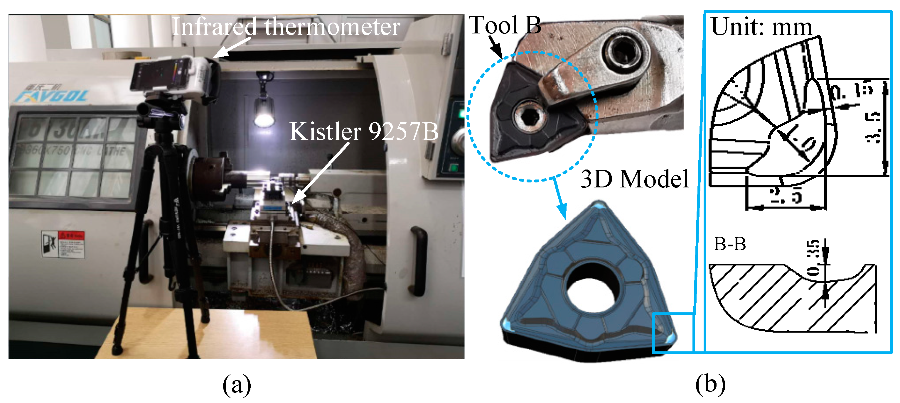
2.1. Tool Design and Manufacturing

In this paper, the micro-groove tool is referred to as Tool B, and the original tool is referred to as Tool A. The geometric angles of Tools A and B are shown in Table 1.
The design process of Tool B is summarized as follows. First, Deform is applied. Tool A is used to cut the AISI 201 for the simulation. The basic geometry and boundary conditions of numerical simulation of the cutting process are shown in Figure 1. The tool is a rigid body, and the workpiece is a plastic body. The tool is fixed, and the workpiece completes the cutting movement along the Y direction at a given speed. An adaptive tetrahedral mesh is adopted for both the cutter and workpiece, with a relative mesh size of 50,000 and a size ratio of 7. The higher tool–chip heat exchange coefficient is used to make the cutting temperature reach the steady state faster, and the value in this work is 2000 kW/(m2·°C). A constitutive model, the friction model and rule of separation of the material were provided by software. The cutting parameters recommended by the manufacturer were used: cutting speed vc = 120 m/min, feed f = 0.16 mm, cutting depth ap = 1.5 mm. In the process of post processing, with respect to the high temperature area of the rake face, the appropriate temperature range (495–779 °C) was selected and the temperature points and the corresponding coordinates’ data were extracted. The data points were input into MATLAB R2016a and the reasonable temperature boundary of the tool surface was determined, as shown in Figure 1. The nonuniform spline curve of temperature field was established in the GRIP program and imported into UG (Unigraphics) software (version 8.5). Based on the nonuniform spline curve, the UG software established a geometric model of micro-groove through the software Boolean resection command. The micro-groove modeling of the rake face was performed, and the 3D model of Tool B was finally established.
As shown in Figure 2, the micro-groove on the rake face changes the tool-chip contact state during cutting. The results show that the contact length between the chip and the tool rake face is reduced, and the tool-chip bonding zone and sliding zone are greatly reduced. Therefore, in the process of chip flow, the cutting resistance decreases. At the same time, when the chip flows through the back wall of the micro-groove, it is blocked and curled, which indirectly reduces the friction between the chip and the auxiliary cutting edge.
Tools A and B were manufactured by the powder metallurgy. The main component was WC, and the surfaces of Tools A and B in the thickness of 3 μm were coated with TiAlN. The micro-groove shape and size of Tool B is shown in Figure 3.

2.2. Cutting Machining

The machining workpiece of Tools A and B is AISI 201, which is a cylindrical bar with a length of 200 mm and a diameter of 80 mm. The physical performance parameters and composition of the tool and workpiece are shown in Table 2 and Table 3. The cutting test was carried out on a CNC (numerical control machine). The cutting parameters wee the same as those used in the cutting simulation.
During the test process, the three-direction cutting forces were measured by a dynamometer (Kistler-9257-B, Kistler Instrumenter AG, Winterthur, Switzerland). Through the previous cutting experiments, it was found that the wear of tool A changed every 2 min. For the tool durability experiment, it was very important to observe the changing process of tool wear. Tools A and B cut for 2 min each time. After each cutting, the tool was removed from the tool holder, cleaned by ultrasonic cleaner and dried by air blower, and the chip was collected. The tool wear was observed under a microscope (BX51-P, Olympus Corporation, Tokyo, Japan). We repeated the test until the wear width of the flank face reached 0.15 mm. After cutting, Tools A and B were cleaned and dried. SEM (Zeiss SUPRA 40; Carl Zeiss AG, Jena, Germany) was used to observe the wear morphology of tools, and the element distribution on the tool surface was detected by EDS (Zeiss SUPRA 40; Carl Zeiss AG, Jena, Germany). The cutting chip morphology was observed by an electron microscope.
In order to understand the cutting mechanism of Tools A and B, Figure 4 shows the chip force diagram of Tools A and B in the cutting process. F and Frs are a pair of balance forces, where F is the force of the tool on the chip, which can be decomposed into the positive pressure Fn and friction force Ff of the tool on the chip, and Frs is the force of the workpiece on the chip, which can be decomposed into the horizontal force Fy and vertical force Fx of the workpiece on the chip.
Tool B has a 0.15 mm micro-groove from the cutting edge. On the one hand, the second rake angle of the rake face increased, reducing the plastic deformation when the rake face extruded the chip and reducing the friction resistance of the chip flowing through the rake face, thus reducing the cutting force and cutting heat. On the other hand, the micro-groove reduced the contact length between the tool and the chip. In the process of chip flowing through the micro-groove, the chip part loses the support of normal force and is in a friction-free state. This reduces the input of cutting energy, reduces the cutting temperature and improves the tool wear.
In the cutting process, almost all the energy consumed by cutting deformation and friction is converted into heat energy, which is the main cause of tool wear, so it is necessary to study the tool-chip friction and cutting energy. The cutting process of Tools A and B meets the three-dimensional oblique cutting conditions. Based on the analysis of the oblique cutting model, the formulas of friction coefficient, sliding energy and shear energy are obtained [34].
tan γ n = tan γ 0 cos λ s
tan φ n = b b c cos γ n 1 b b c sin γ n
v s = cos λ s cos φ n v cos η c cos ( φ n γ n )
v c = cos λ s sin φ n v cos η c cos ( φ n γ n )
F s = ( F x cos λ s F y sin λ s ) 2 + ( F x sin λ s cos φ n + F y cos λ s cos φ n + F z sin φ n ) 2
F n = F x sin λ s cos γ n + F y sin γ n + F z cos λ s cos γ n
μ = F f F n
E s = F s v s v a w a = F s v s v a p f
E f = F f v c v a w a = F f v c v a p f
In the formula, γn, λs, φn, b and bc represent the forward angle, inclination angle, normal shear angle, cutting thickness and chip thickness, respectively. Fx, Fy, Fz, vs, vc, v and ηc denote thrust force, main cutting force, feed force, shear speed, chip speed, cutting speed and chip flow angle, respectively. μ, Es and Ef represent friction coefficient, shear energy and sliding energy, respectively. Table 1 provides the values of γo and λs. Generally, in the calculation, the value of ηc is equal to λs. Other parameters such as b, ap, v and f are obtained from the cutting parameters of the cutting experiment. Fx, Fy, Fz and bc can be obtained by measurement. Combined with Equations (1)–(9), μ, Es and Ef can be calculated.
In the third part of the paper, we calculate μ, Es and Ef, and analyze and discuss the reason of their change with time.

3. Results and Discussion

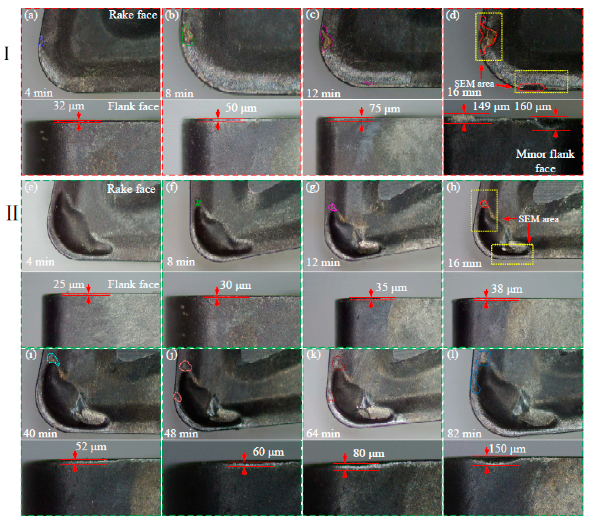
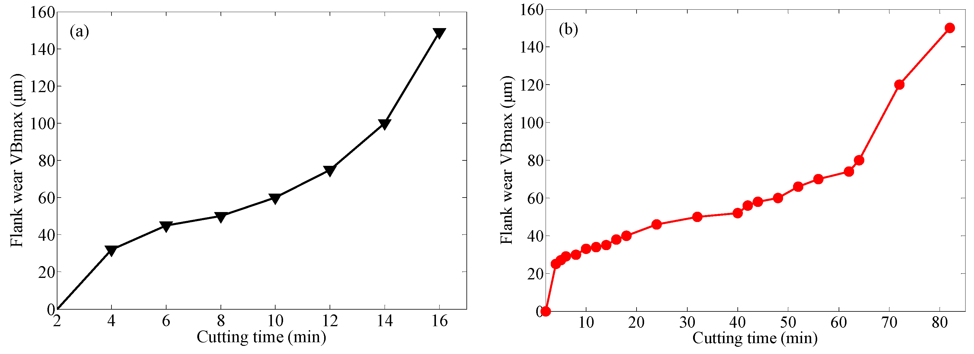
3.1. Wear Morphology and Wear Curve of Tools A and B

Generally, the standard of tool failure is that the wear width of the flank face reaches 0.15 to 0.3 mm but, when cutting stainless steel 201 material, it is found that when the wear width of the flank face reaches 0.15 mm the surface roughness of the workpiece is poor; the maximum roughness value is more than 2 mm. Therefore, when the flank face wear width reaches 0.15 mm after the cutting experiment, the tool stops cutting.
We conducted three repeated tests, and the test values are shown in Table 4. From the table, we can see that the dispersion of the wear value of the flank after three times is small, and the data is reliable. Therefore, the wear value takes the average value of three experiments. After the cutting life test, Tool A and Tool B cut for 16 and 82 min, respectively.
Figure 5 shows images of the change in the wear topography of the rake and flank faces of Tools A and B. It can be seen from Figure 5 that the wear of the main cutting edge and the auxiliary cutting edge near the rake face of Tool A increased rapidly with the cutting time. The material near the main cutting edge peeled off from 12 to 16 min, forming obvious crater wear. Crater wear started from 4 min near the auxiliary cutting edge. Due to the high-speed chip flow through the surface near the auxiliary cutting edge, serious friction occurred, and the material on the tool surface was taken away quickly, forming serious crater wear. The crater wear proportion was largest when cutting at 16 min. From 4 to 16 min, the wear width of flank face of Tool A increased rapidly from 32 to 149 μm. When the cutting time reached 16 min, the wear width near the auxiliary flank reached 160 μm due to serious crack wear near the auxiliary cutting edge. However, Tool B cut for a total of 82 min, and its service life was 5 times higher than that of Tool A. As can be seen from Figure 5, from 4 to 48 min, the rake face wear near the main and auxiliary cutting edges of the rake face of Tool B shows little change. When the cutting time reached 64 min, the rake face pit wear increased rapidly, and when the cutting time reached 82 min, the pit wear reached the maximum. The wear width of Tool B flank increases slowly from 4 to 82 min, and the wear width increases from 25 to 150 μm.
As can be seen from Figure 6a, the cutting process of Tool A has three stages: initial wear, stable wear and intensified wear. The face wear of Tool A increased rapidly from 2 to 5 min, which is in the initial stage. At 5 to 10 min, the cutter was in a stable wear stage, and the wear width changed slowly. After 10–12 min, the wear width of the cutter face rapidly increased to 125 μm, which is in the stage of intensified wear. After 12–16 min, the wear width of the cutter face uniformly increased to 150 m, reaching the specified wear width. As shown in Figure 6b, the flank wear process of Tool B is more complicated. The flank wear width increased rapidly after 2–4 min, which is in the initial stage. In 4–36 min, the tool was in the first stable wear stage, and the wear width changed slowly. The 36–44 min cutter was in the first stage of intensified wear, and the wear width increased rapidly to 97 m. Furthermore, during the 44–62 min period, the cutter was in the second stage of stability with little change in wear width. After 62–64 min, the tool surface wear rapidly increased to 142 μm, and the tool was in the second stage of intensified wear. After 64–82 min, the tool surface wear slowly increased to 150 μm, reaching the specified wear width. The micro-groove of Tool B reduced the friction between and the tool and the chip, reducing the cutting force and cutting temperature and slowed down the wear of the flank face.
As can be seen from Figure 7a, from 4 to 16 min, the crater wear area of the auxiliary cutting edge of Tool A pair increased rapidly with time, and the change rate of the crater wear area was high. Crater wear near the main cutting edge mainly occurred between 12 and 16 min. Because the temperature of Tool A increased rapidly with the cutting time, the strength and chip breaking ability of Tool A decreased because of the thermal softening effect. When high-temperature chips flew out from the rake surface, the field near the auxiliary cutting edge was severely rubbed, and the crater wear area increased rapidly. As can be seen from Figure 7b, due to the insertion of the micro-groove on the rake face of Tool B, the contact area of Tool B chips was small, the temperature growth of Tool B was small and the crater wear near the auxiliary cutting edge was slow. Furthermore, the wear area was smaller, and no crater wear occurred near the main cutting edge. Compared with Tool A, the crater wear area near the auxiliary cutting edge of Tool B was divided into two parts due to the existence of the micro-groove, and the wear area was greatly reduced.

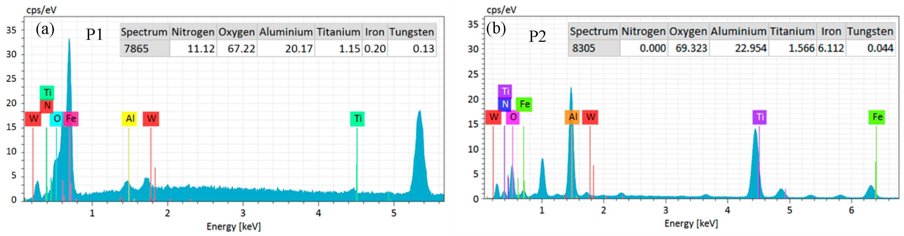
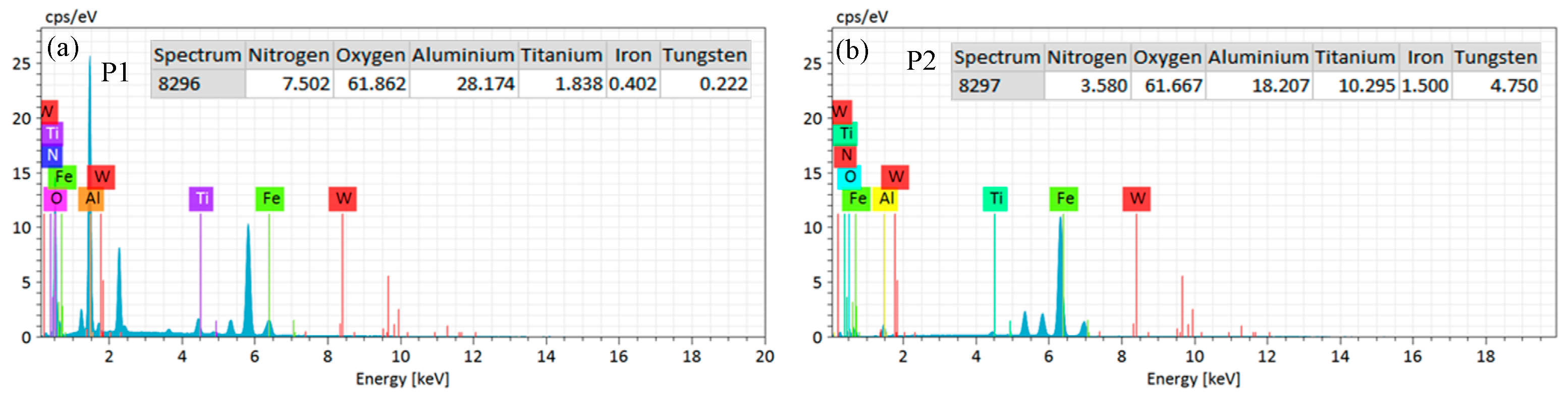
3.2. Wear Mechanism Analysis

The primary reason for tool wear is the input of cutting energy, which is closely related to cutting force and cutting temperature. During the cutting process, the cutting energy is mainly shear energy and friction energy. In order to investigate the change rule of cutting energy in the cutting process of Tools A and B, an experiment of tool durability was carried out. The Tools A and B cutting AISI 201 took 16 and 82 min, respectively, and the wear width of the flank face reached 150 μm.
The three-way cutting forces during the cutting process were measured using a Kistler-9257-B. We repeated three cutting durability experiments. As shown in Table 5, the numerical discrete value of the cutting force of the three experiments was within a reasonable range, and the data was reliable. The average values were taken as the data presented in the paper.
It can be seen from the Figure 8 that Tool A only cut for 16 min, and the three-way cutting forces of Tool B at the corresponding time point was less than that of Tool A, with a reduction of more than 20%. When the cutting time was 10 min, the main cutting force Fy of Tool B decreased by 24.7%, the cutting depth resistance force Fx decreased by 32.5% and the feed resistance force Fz decreased by 38.3%. After cutting for 60 min, the main cutting force of Tool B greatly increased. During the cutting process, the cutting temperature was measured by an infrared thermometer, as shown in Figure 9. It can be seen from the figure that comparing Tool A with Tool B between 0 and 16 min, temperatures decreased by more than 20%. When the cutting time was 10 min, the cutter tip temperatures of Tools A and B were 723.2 and 566.8 °C, respectively, and the cutter tip temperature of Tool B was decreased by 21.63%. When the cutting time exceeded 60 min, the cutting temperature rapidly increased, and when the cutting time reached 82 min, the cutting temperature reached 785.8 °C.
The friction coefficient, shear energy and sliding energy of Tool A and Tool B in the cutting process were calculated by measuring the cutting force in the three directions of the tool combined with the tool parameters in Table 1 and Equations (1)–(9). As shown in Figure 10a,b, during the cutting process, the friction coefficient of the cutting chip of Tool B was always lower than that of Tool A. The maximum friction coefficient of Tool B was 0.685, and the lowest friction coefficient of Tool A was 0.722. It can be seen from Figure 11a–d that when the cutting time was from 2 min to 16 min, the shear energy of Tool A was from 3785.2 to 5266.3 MJ/m3; at the same time frame, the shear energy of Tool B was greatly decreased. The sliding energy of Tool A was increased from 1009.9 to 1193.4 MJ/m3, and the friction energy of Tool B was decreased by more than 40% at the same moment. It can be seen from Figure 8 that the three-dimensional cutting forces of Tool B were greatly reduced compared to Tool A, and the inputs of shear energy and sliding energy of Tool B were less.
We can compare the flank wear curve with the crater wear area curve of the rake face of Tool A and Tool B, as shown in Figure 12. For Tool A and Tool B, the two curves have sufficient consistency. It can be seen from Figure 12a that when Tool A was cutting for 0–4 min, the wear was in the initial stage, and the wear width of the flank increased rapidly. At the same time, the crater wear area increased rapidly. After 4–14 min, it was in a stable change stage, and the crater wear changed slowly. When the cutting exceeded 14 min, it was in the rapid increase stage—the flank wear width was intensified and the crater wear area also showeda rapid increase. For Figure 12b, when cutting for 0–4 min for Tool B, both the flank wear width and the crater wear area increased rapidly. When the cutting time was 4–64 min, the flank wear was in a stable change stage, and the crater wear area changed gently. From 64 to 82 min, the flank wear width and crater wear area were in a state of aggravation. In general, Tool A had larger crater wear area and a higher change rate.
The change of crater wear area is consistent with the change of cutting forces in Figure 8, the change of temperature in Figure 9, the change of friction coefficient in Figure 10 and the change of shear energy and friction energy in Figure 11, especially in the stage of severe wear. In the initial stage of wear, the flank face is subjected to large positive pressure, the tool wear speed is fast and the rake face is subject to chip extrusion friction, and thus, the wear area increases rapidly. In the normal wear stage, the contact surface between the flank face and the workpiece becomes larger, the work becomes stable and the wear is relatively slow. The rake face adapts to the normal extrusion and friction of the chip, and the wear area changes slowly. In the stage of rapid wear, the tool wear reaches a certain stage, the cutting force and cutting temperature rise sharply, the abrasive wear of the rake face increases rapidly and the crater area grows rapidly.

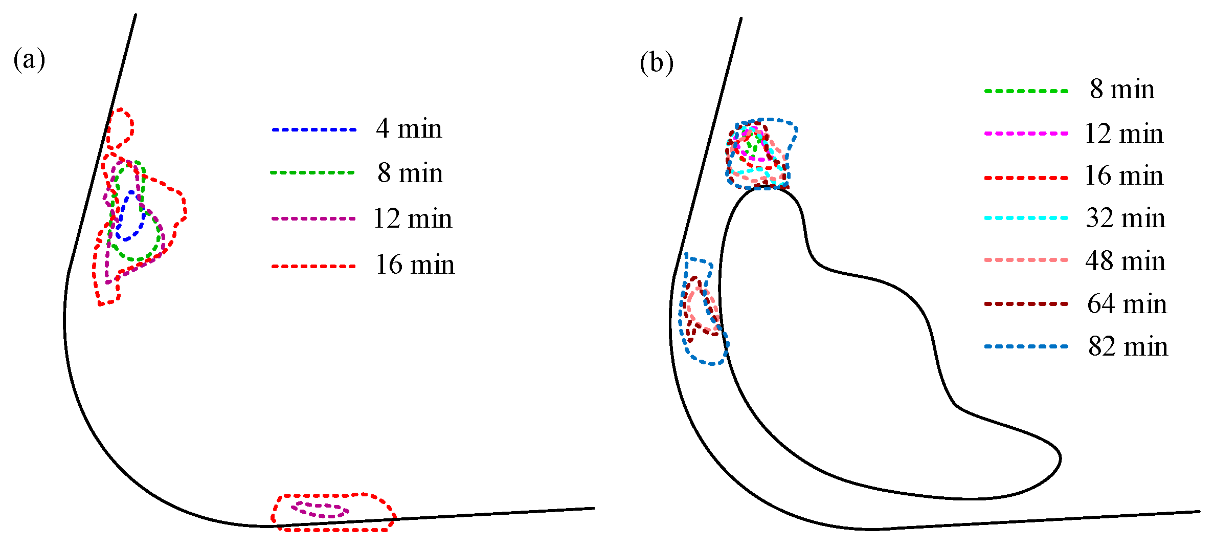
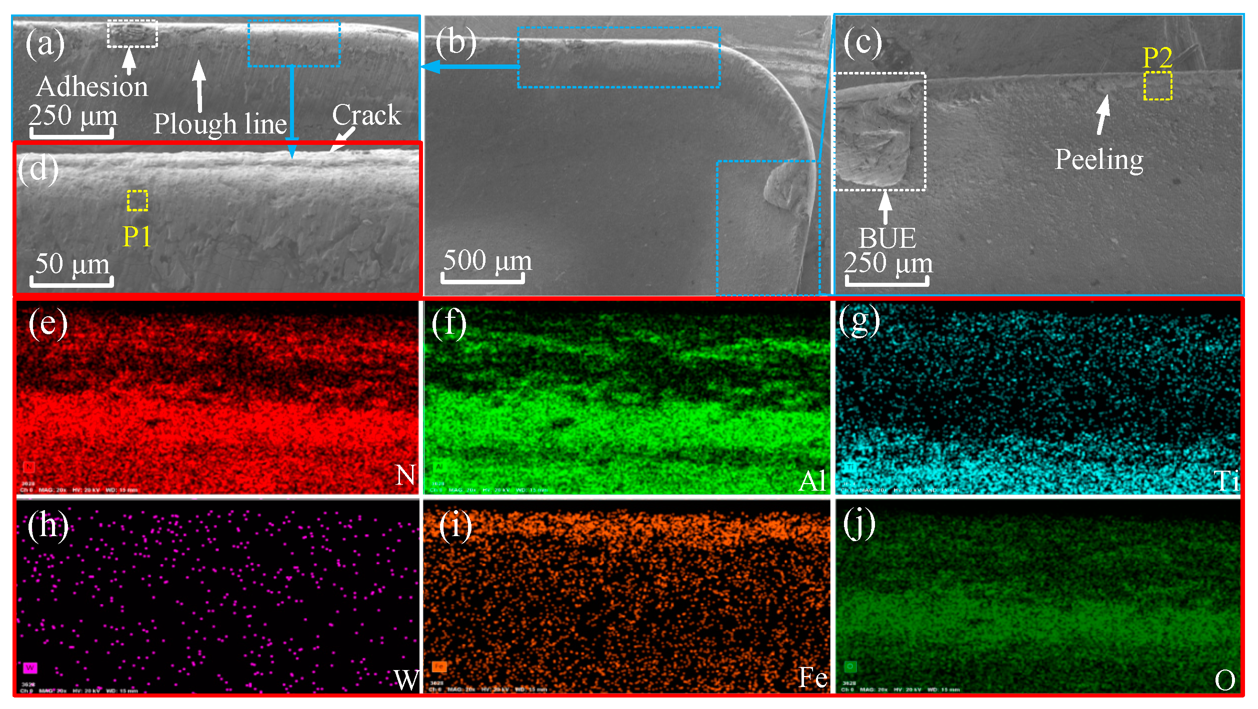
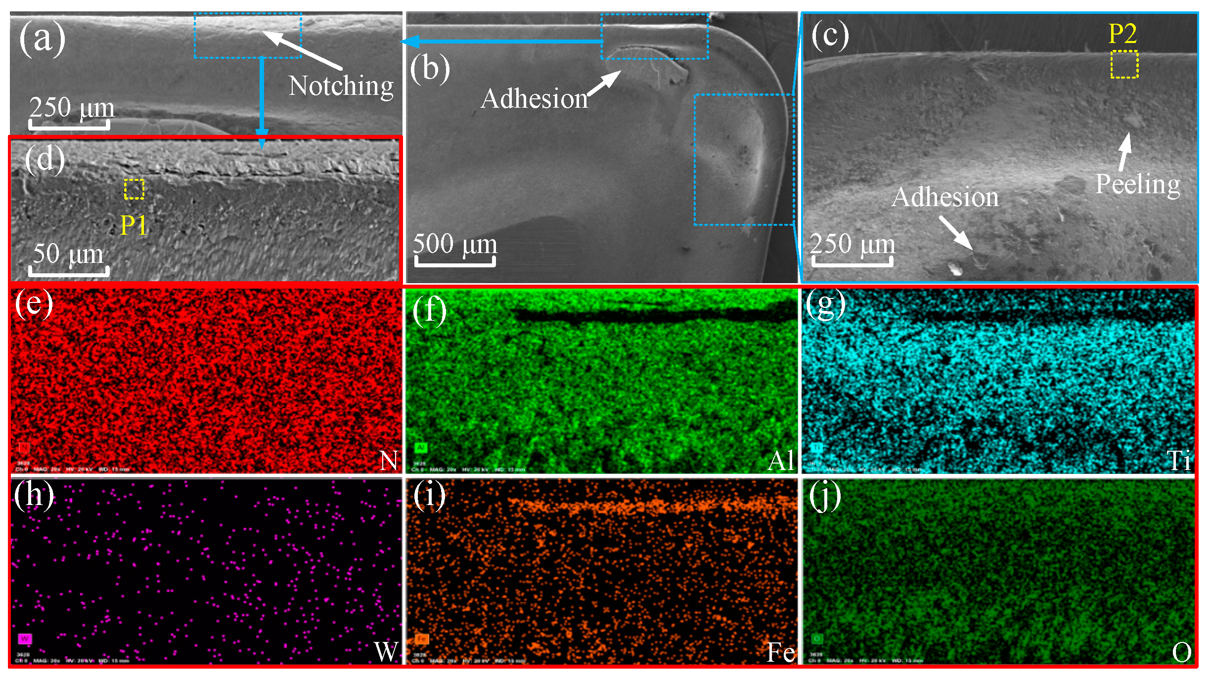
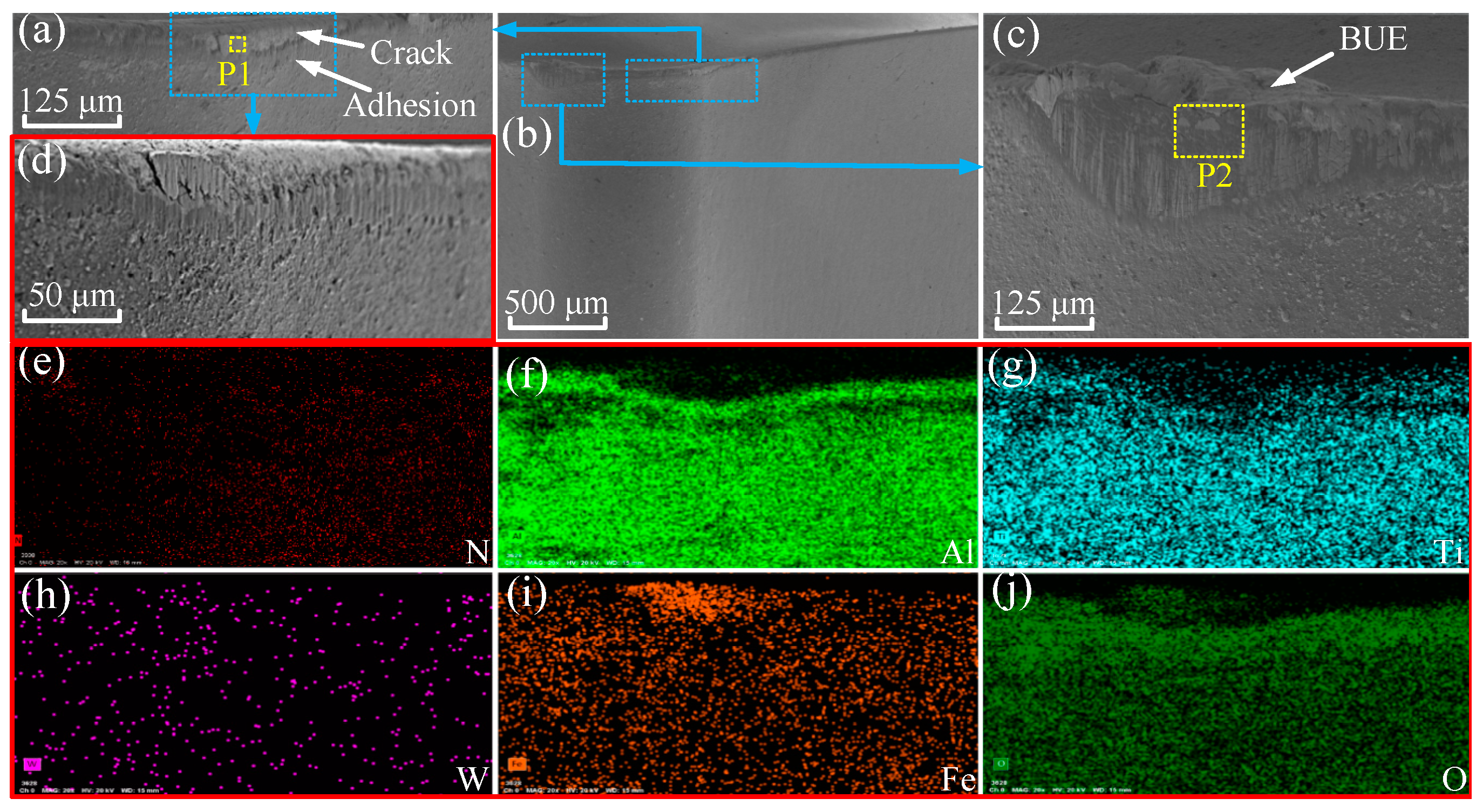
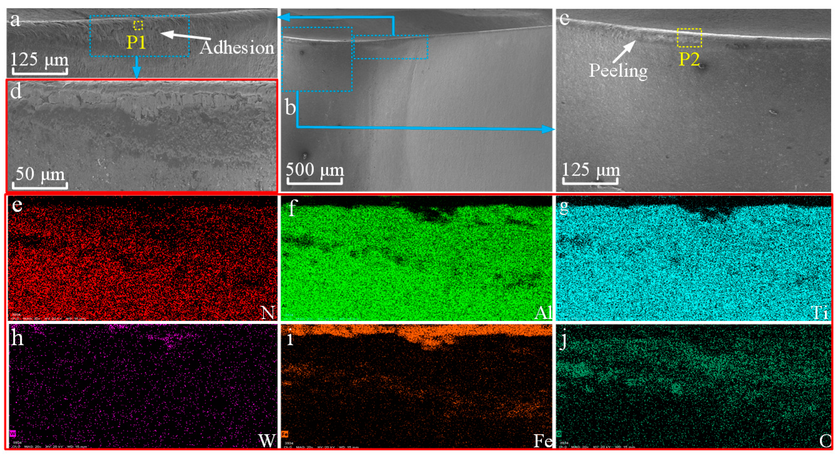
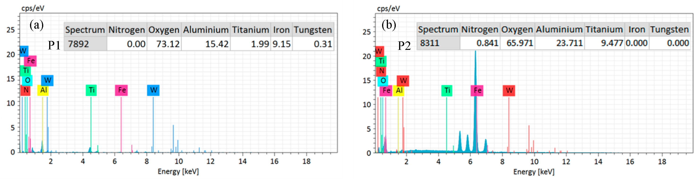
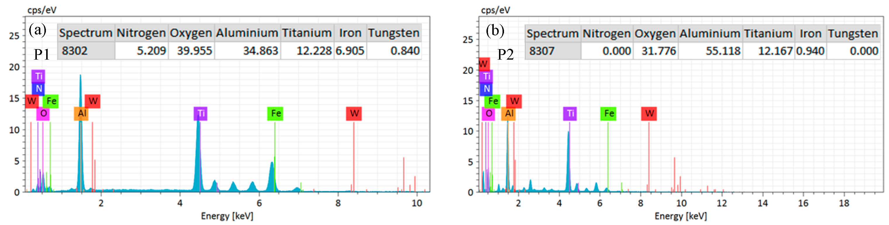
3.3. Wear Analysis of Rake Face

After the cutting durability experiment for Tools A and B, we observed and analyzed the rake face of the tools using SEM and EDS. As shown in Figure 13a–d and Figure 14a–d, compared with Tool B, the abrasive lines on the rake face of Tool A are clear and neat, the peeling of materials near the cutting edge is more serious and the abrasive wear is more serious. The adhesive wear of Tool B mainly occurred inside the micro-groove, while the adhesive wear of Tool A was more serious in the area near the main cutting edge and auxiliary cutting edge. By comparing the distribution of elements in the corresponding areas of the Tools A and B in Figure 13e–j and Figure 14e–j, it can be seen that the distribution area and concentration of the N, Al and Ti elements in Tool B are larger. These three elements are the coating materials of the tool, indicating that the friction state of Tool B is better. The W element distribution of Tools A and B is similar, but for Fe and O elements, the distribution area and concentration of Tool B are smaller. Fe is an element in the workpiece, attached to the surface of the tool by the friction between the tool and the cutting chip. O is an element in the air, attached to the tool surface mainly through the oxidation reaction, indicating that the bonding wear and oxidation wear of Tool B are less significant.
The scan point is selected by selecting the more pronounced area of tool wear. By comparing the energy spectra of the corresponding points in Figure 15 and Figure 16, the percentage of the Fe and O of Tool A is higher, indicating that in the severe area of tool wear, the bonding wear and oxidation wear of Tool B are less significant.

3.4. Wear Analysis of Flank Face of Tools

The flank face of Tools A and B were observed and analyzed by the SEM and EDS in the same way. As shown in Figure 17a–d and Figure 18a–d, compared with Tool B, the peeling of the surface material near the main cutting edge of Tool A is more obvious, and the micro-breakage edge is more serious. Especially for the auxiliary cutting edge of Tool A, there is obvious tool edge breakage and a serious built-up edge, while for Tool B, there is only micro-peeling of the material of the auxiliary cutting edge. By comparing Figure 17e–j and Figure 18e–j, it is found that the distribution area of N, Al and Ti coating material elements of Tool B is larger and denser, and the element concentration is obviously higher than that of Tool A, indicating that the abrasive wear of Tool B is slighter. For the element W, the concentration of Tool A is higher than that of Tool B, indicating that the coating material on the surface of Tool A is badly worn and has exposed the matrix material inside the tool. The distribution area of the Fe and O elements on Tool B is significantly lower than that of Tool A, and the concentration of these two elements is lower, indicating that the bonding and oxidation wear of Tool B is less than that of Tool A.
Similarly, the severe wear area on the flank face was selected as the scanning point, and the analysis was conducted by the energy spectrum. As shown in Figure 19 and Figure 20, the O contents of Point P1 and P2 of Tool A are 73.12% and 65.971%, respectively, while the corresponding points of Tool B are only 39.955% and 31.776%, respectively, indicating that the oxidation wear of Tool A was more serious in this area, while the Fe contents of Tools A and B were relatively close.
A symmetrical conical texture was prepared on the rake face [21], and the cutting time was set to 3 min. It was found that the conical texture can store coolant and reduce the friction between tool and chip. Combining the micro texture design of the tool with the nano fluid conditions, it was found that the cutting force of the tool was significantly reduced. Through the preparation of micro groove texture parallel to the cutting edge on the tool rake face [22], it was found that the tool wear rate decreased by 63.3% under the conditions of the nano-fluid. The above findings are consistent with the research conclusions of this paper. The previous research of our team mainly focused on the design of tool micro groove based on the temperature field [34,35]. Through the durability test, it was found that the service life of the tool was greatly improved, but it did not exceed twice the service life of the original tool. In this paper, combined with the temperature field and the characteristics of tool chip friction in the tool test, a micro groove was designed, the durability of the tool is greatly improved, and the service life was five times that of the original tool. This is because in the cutting process, the chips not only had severe friction near the cutting edge, but also had severe friction near the auxiliary cutting edge when the chips flew out. At the same time, some chips almost collided in these two areas. Therefore, in this study, the temperature field and chip wear field were designed at the same time, the contact area between tool and chip in the whole cutting process was greatly reduced, the friction between tool and chip and tool wear were greatly reduced, and the service life of the tool was prolonged.

4. Conclusions

In order to improve the performance and service life of cutting tools, in this work we designed a micro-groove structure 0.15 mm away from the cutting edge. Through cutting theory and experimental research, the cutting performance of Tool A and Tool B in cutting AISI 201 was compared. The results show that Tool B had sufficient cutting performance. Tool B has been put into production for an enterprise and is widely used in material processing in military and commercial enterprises. Due to the characteristics of difficult-to-cut machine materials, the application of Tool B in high-speed cutting needs to be further studied. The specific conclusions are as follows:
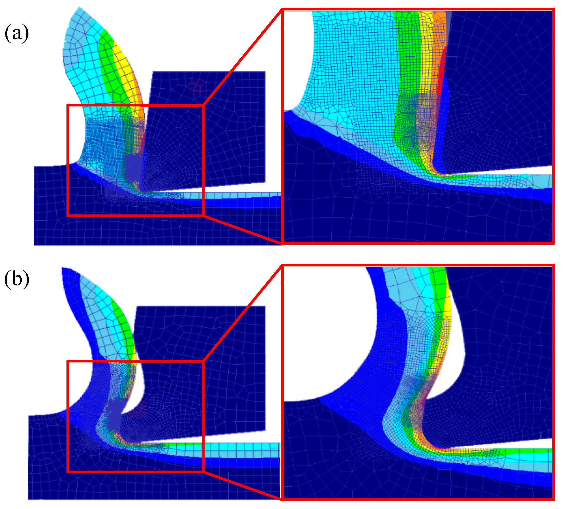
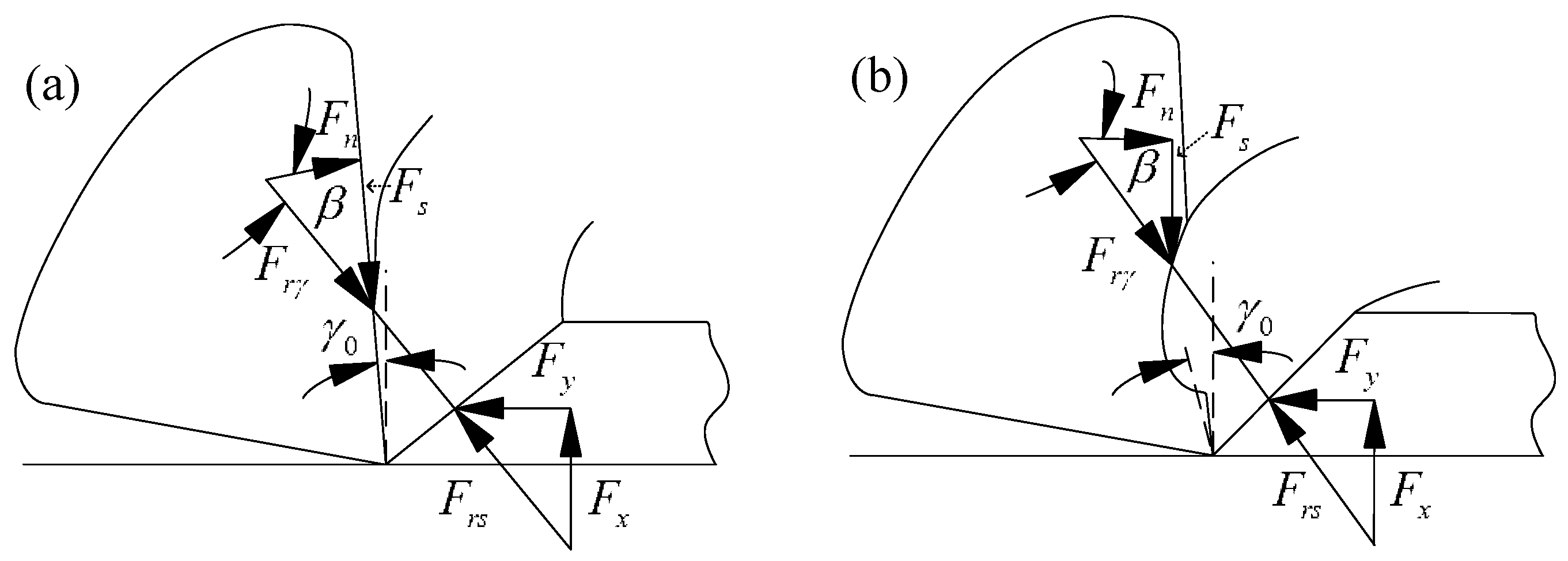
  • The micro-groove reduced the tool-chip contact area. The length of the tool–chip sticking friction zone and sliding friction zone was decreased, and the micro-groove increased the second rake angle of the tool; hence, as the tool-chip friction abated and the cutting resistance decreased, the input of cutting energy was reduced.
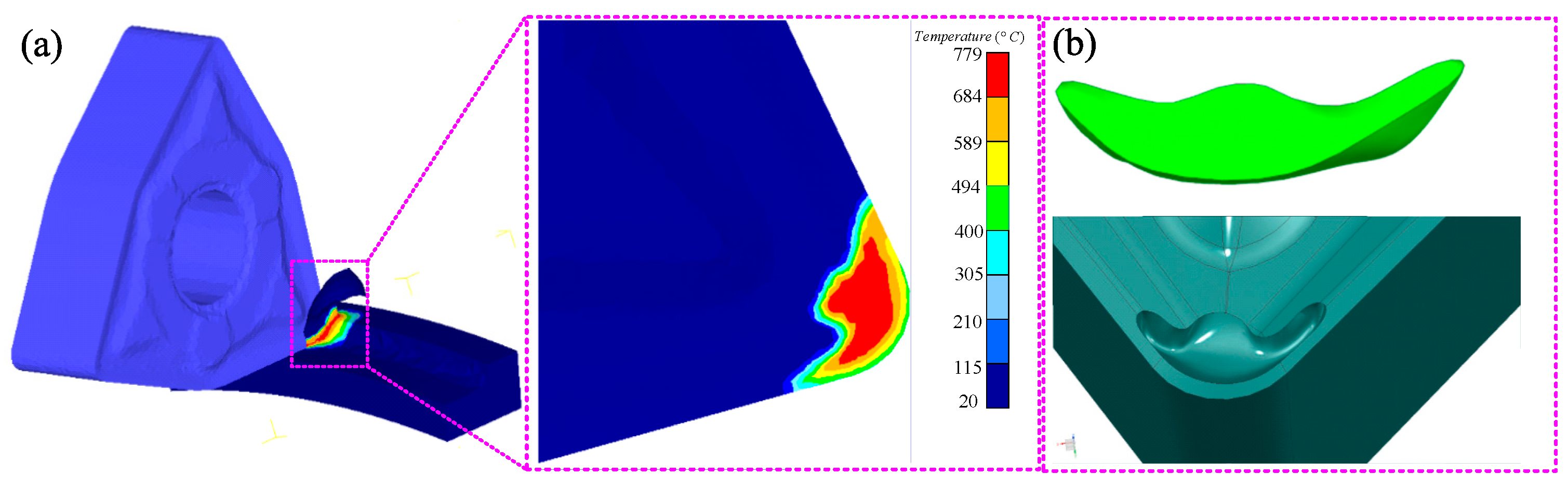
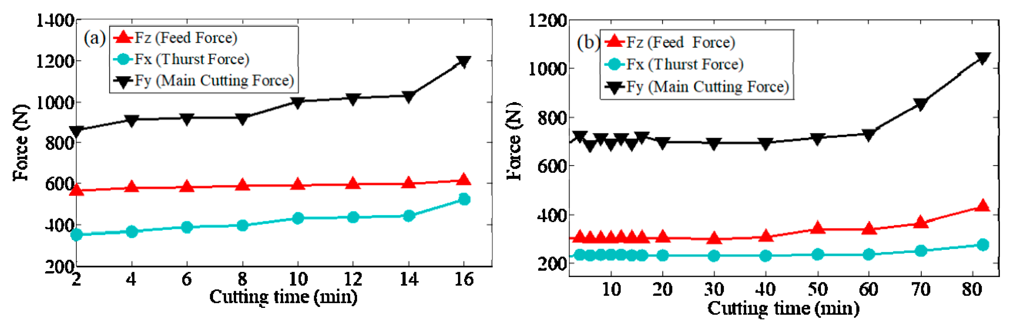
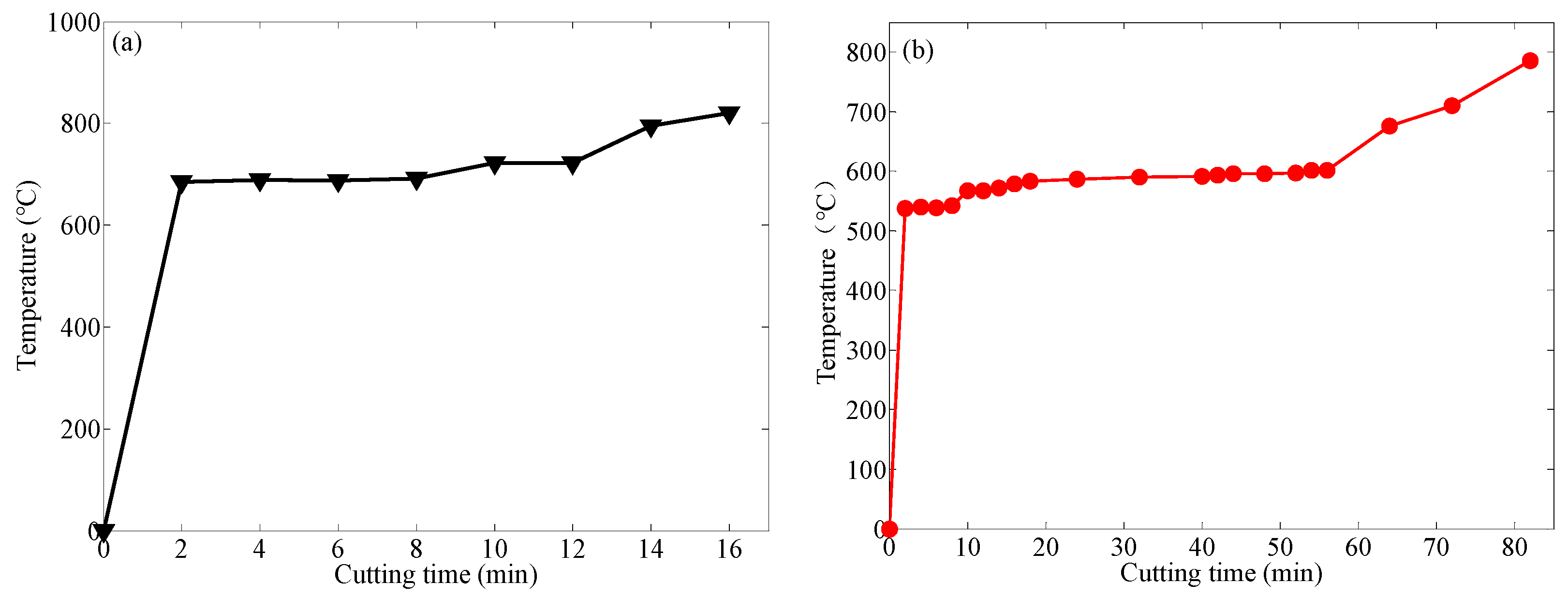
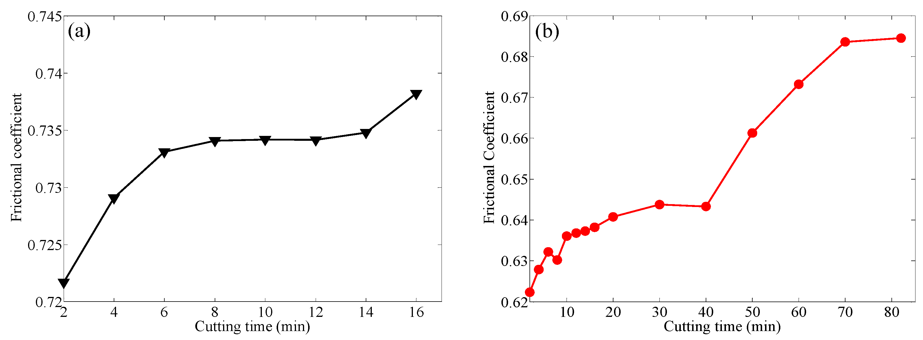
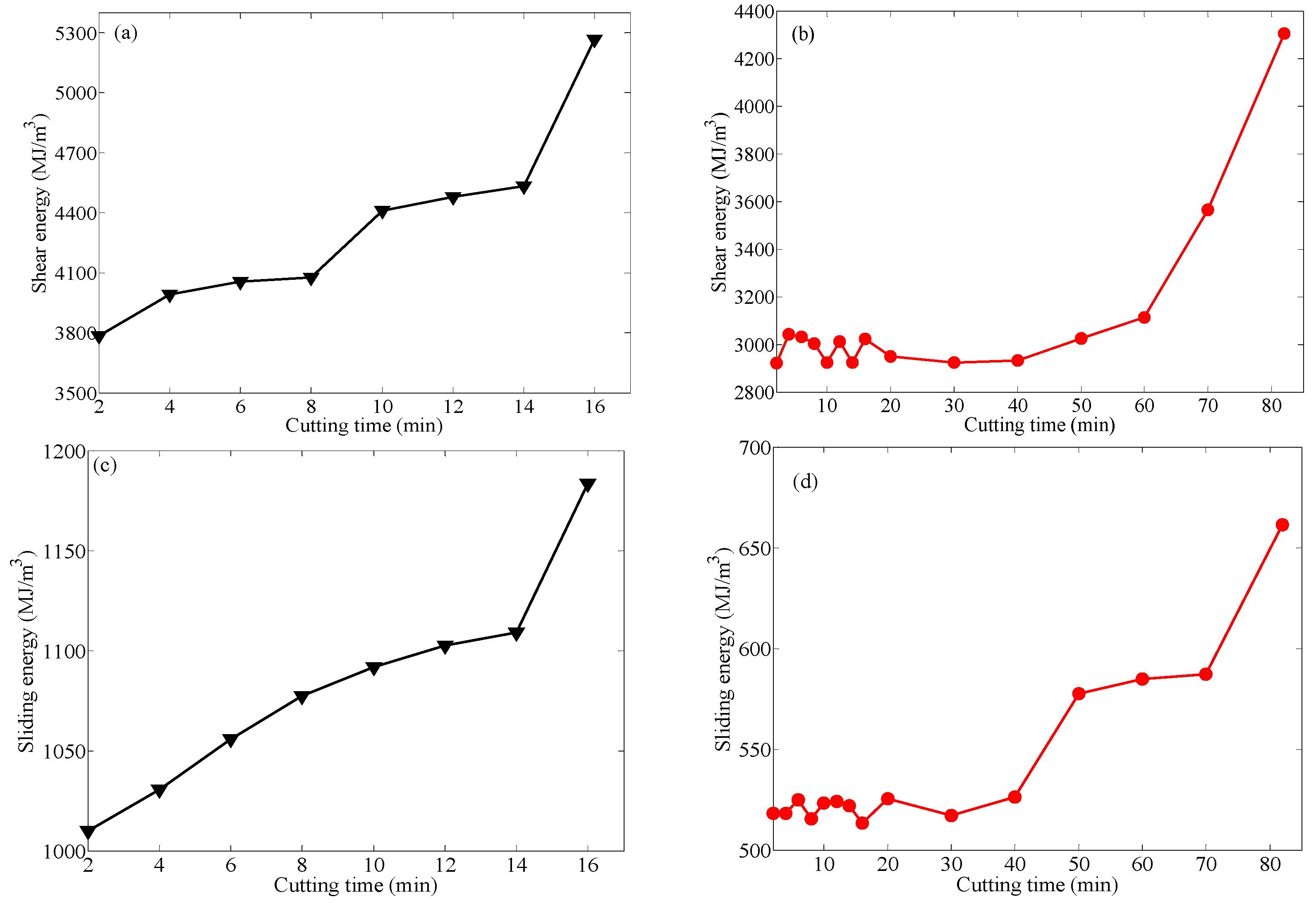
  • Compared with Tool A, Tool B three-direction cutting forces decreased by more than 20%, the cutting temperature dropped by more than 20%, the tool friction coefficient decreased by more than 14% and the friction energy and shear energy were greatly reduced at the same time during the cutting process.
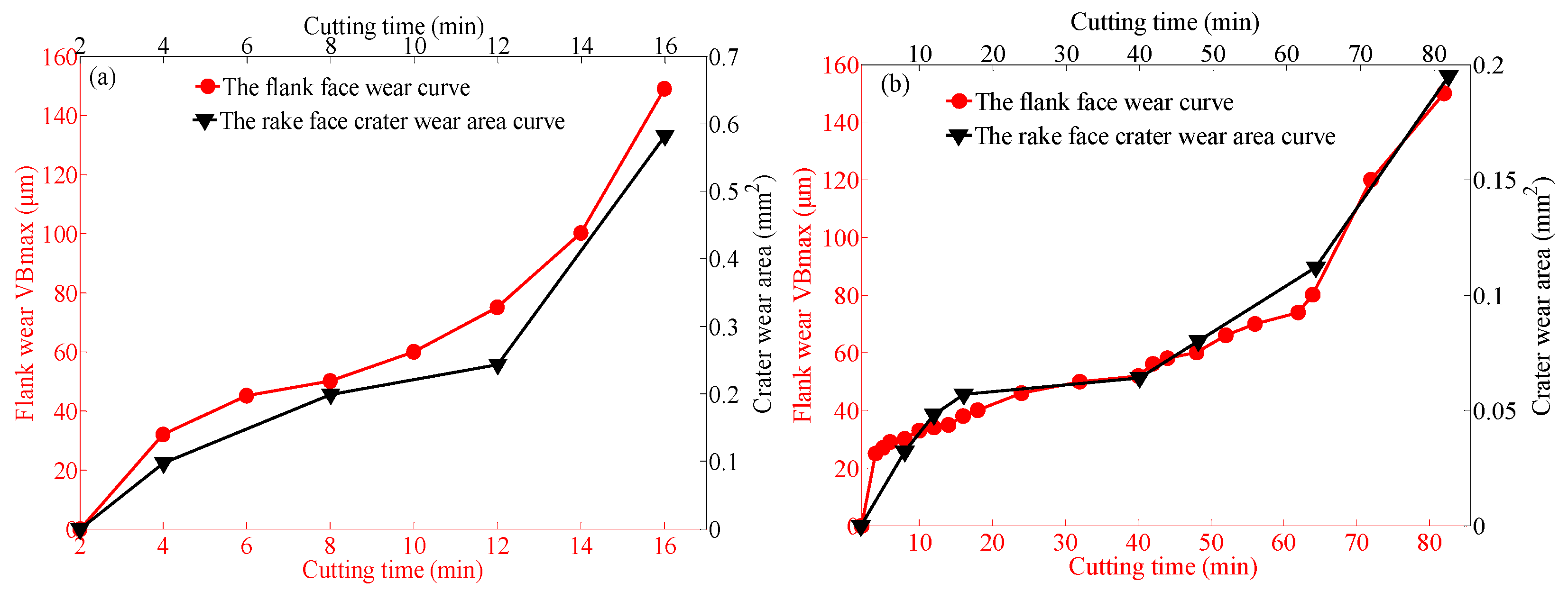
  • The crater wear area variance was consistent with the change in the flank wear width. In the severe wear stage, the crater wear area and cutting force, cutting temperature, shear energy and friction energy had the same change trend with time. The adhesive wear and oxidation wear of the rake and flank face of Tool B were less pronounced.
  • The chip thickness of Tool B was reduced by 15%, which indicates that the cutting energy input was lower and the chip curl radius was smaller, indicating that the chip rolling ability of Tool B was stronger.
  • Through the cutting test, due to the smaller three-direction cutting forces, lower temperature and less tool wear, Tool B cut for 82 min, Tool A cut for 16 min and the service life of Tool B was greatly improved.

Author Contributions

Conceptualization, J.W.; data curation, Z.Z. (Zhongfei Zou) and Z.Z. (Zichuan Zou); formal analysis, J.W. and P.T.; funding acquisition, L.H.; investigation, L.H.; methodology, J.W.; software, Y.W. and F.D.; supervision, C.Z.; validation, G.Z.; writing—original draft, T.Z.; writing—review and editing, X.Z. All authors have read and agreed to the published version of the manuscript.

Funding

This study was supported by the National Natural Science Foundation of China (Grant No.51765009); and the Science and Technology Planning Project of Guizhou (Grant No. [2019]1166); Guizhou Provincial Department of education KY word [2020]248.

Institutional Review Board Statement

Not applicable.

Informed Consent Statement

Not applicable.

Data Availability Statement

Data sharing is not applicable to this article.

Conflicts of Interest

There is no conflict of interest for the authors.

References

  1. Etsion, I. Improving tribological performance of mechanical components by laser surface texturing. Tribol. Lett. 2004, 17, 733–737. [Google Scholar] [CrossRef]
  2. Shum, P.W.; Zhou, Z.F.; Li, K.Y.J.T.I. Investigation of the tribological properties of the different textured DLC coatings under reciprocating lubricated conditions. Tribol. Int. 2013, 65, 259–264. [Google Scholar] [CrossRef]
  3. Chetan; Ghosh, S.; Rao, P.V. Application of sustainable techniques in metal cutting for enhanced machinability: A review. J. Clean. Prod. 2015, 100, 17–34. [Google Scholar] [CrossRef]
  4. Singh, A.; Ghosh, S.; Aravindan, S. Influence of dry micro abrasive blasting on the physical and mechanical characteristics of hybrid PVD-AlTiN coated tools. J. Manuf. Process. 2019, 37, 446–456. [Google Scholar] [CrossRef]
  5. Padmini, R.; Krishna, P.V.; Rao, G.K.M. Effectiveness of vegetable oil based nanofluids as potential cutting fluids in turning AISI 1040 steel. Tribol. Int. 2016, 94, 490–501. [Google Scholar] [CrossRef]
  6. Chetan; Ghosh, S.; Rao, P.V. Comparison between sustainable cryogenic techniques and nano-MQL cooling mode in turning of nickel-based alloy. J. Clean. Prod. 2019, 231, 1036–1049. [Google Scholar] [CrossRef]
  7. Chaabani, S.; Arrazola, P.J.; Ayed, Y.; Madariaga, A.; Tidu, A.; Germain, G. Comparison between cryogenic coolants effect on tool wear and surface integrity in finishing turning of Inconel 718. J. Mater. Process. Technol. 2020, 285, 16. [Google Scholar] [CrossRef]
  8. Senatore, A.; Risitano, G.; Scappaticci, L.; D’Andrea, D. Investigation of the tribological properties of different textured lead bronze coatings under severe load conditions. Lubricants 2021, 9, 34. [Google Scholar] [CrossRef]
  9. Beake, B.D.; Ning, L.; Gey, C.; Veldhuis, S.C.; Komarov, A.; Weaver, A.; Khanna, M.; Fox-Rabinovich, G.S. Wear performance of different PVD coatings during hard wet end milling of H13 tool steel. Surf. Coat. Technol. 2015, 279, 118–125. [Google Scholar] [CrossRef]
  10. Nevesa, D.; Diniz, A.E.; Lima, M.S.F. Microstructural analyses and wear behavior of the cemented carbide tools after laser surface treatment and PVD coating. Appl. Surf. Sci. 2013, 282, 680–688. [Google Scholar] [CrossRef] [Green Version]
  11. Mo, J.L.; Zhu, M.H.; Leyland, A.; Matthews, A. Impact wear and abrasion resistance of CrN, AlCrN and AlTiN PVD coatings. Surf. Coat. Technol. 2013, 215, 170–177. [Google Scholar] [CrossRef]
  12. Liu, W.; Chu, Q.Q.; Zeng, J.J.; He, R.X.; Wu, H.D.; Wu, Z.W.; Wu, S.H. PVD-CrAlN and TiAlN coated Si3N4 ceramic cutting tools—1. Microstructure, turning performance and wear mechanism. Ceram. Int. 2017, 43, 8999–9004. [Google Scholar] [CrossRef]
  13. Vereschaka, A.; Grigoriev, S.; Tabakov, V.; Migranov, M.; Sitnikov, N.; Milovich, F.; Andreev, N. Influence of the nanostructure of Ti-TiN-(Ti,Al,Cr)N multilayer composite coating on tribological properties and cutting tool life. Tribol. Int. 2020, 150, 16. [Google Scholar] [CrossRef]
  14. Ling, T.D.; Liu, P.Z.; Xiong, S.W.; Grzina, D.; Cao, J.; Wang, Q.J.; Xia, Z.C.; Talwar, R. Surface texturing of drill bits for adhesion reduction and tool life enhancement. Tribol. Lett. 2013, 52, 113–122. [Google Scholar] [CrossRef]
  15. Zhou, R.; Cao, J.; Wang, Q.J.; Meng, F.M.; Zimowski, K.; Xia, Z.C. Effect of EDT surface texturing on tribological behavior of aluminum sheet. J. Mater. Process. Technol. 2011, 211, 1643–1649. [Google Scholar] [CrossRef]
  16. Liu, G.L.; Huang, C.Z.; Su, R.; Ozel, T.; Liu, Y.; Xu, L.H. 3D FEM simulation of the turning process of stainless steel 17-4PH with differently texturized cutting tools. Int. J. Mech. Sci. 2019, 155, 417–429. [Google Scholar] [CrossRef]
  17. Kummel, J.; Braun, D.; Gibmeier, J.; Schneider, J.; Greiner, C.; Schulze, V.; Wanner, A. Study on micro texturing of uncoated cemented carbide cutting tools for wear improvement and built-up edge stabilisation. J. Mater. Process. Technol. 2015, 215, 62–70. [Google Scholar] [CrossRef]
  18. Ahmed, Y.S.; Paiva, J.M.; Arif, A.F.M.; Amorim, F.L.; Torres, R.D.; Veldhuis, S.C. The effect of laser micro-scale textured tools on the tool-chip interface performance and surface integrity during austenitic stainless-steel turning. Appl. Surf. Sci. 2020, 510. [Google Scholar] [CrossRef]
  19. Zhang, K.D.; Deng, J.X.; Xing, Y.Q.; Li, S.P.; Gao, H.H. Effect of microscale texture on cutting performance of WC/Co-based TiAlN coated tools under different lubrication conditions. Appl. Surf. Sci. 2015, 326, 107–118. [Google Scholar] [CrossRef]
  20. Zhang, N.; Yang, F.; Jiang, F.; Zhang, Y.; Liu, G. Investigation of tribological performance of micro-groove textured cemented carbide surfaces. Surf. Eng. 2020, 36, 1190–1199. [Google Scholar] [CrossRef]
  21. Pang, M.H.; Nie, Y.F.; Ma, L.J. Effect of symmetrical conical micro-grooved texture on tool-chip friction property of WC-TiC/Co cemented carbide tools. Int. J. Adv. Manuf. Technol. 2018, 99, 737–746. [Google Scholar] [CrossRef]
  22. Zhou, C.C.; Guo, X.H.; Zhang, K.D.; Cheng, L.; Wu, Y.Q. The coupling effect of micro-groove textures and nanofluids on cutting performance of uncoated cemented carbide tools in milling Ti-6Al-4V. J. Mater. Process. Technol. 2019, 271, 36–45. [Google Scholar] [CrossRef]
  23. Alagan, N.T.; Zeman, P.; Hoier, P.; Beno, T.; Klement, U. Investigation of micro-textured cutting tools used for face turning of alloy 718 with high-pressure cooling. J. Manuf. Process. 2019, 37, 606–616. [Google Scholar] [CrossRef]
  24. Guo, D.L.; Guo, X.H.; Zhang, K.D.; Chen, Y.D.; Zhou, C.C.; Gai, L.W. Improving cutting performance of carbide twist drill combined internal cooling and micro-groove textures in high-speed drilling Ti6Al4V. Int. J. Adv. Manuf. Technol. 2019, 100, 381–389. [Google Scholar] [CrossRef]
  25. Fang, Z.L.; Obikawa, T. Cooling performance of micro-texture at the tool flank face under high pressure jet coolant assistance. Precis. Eng. 2017, 49, 41–51. [Google Scholar] [CrossRef]
  26. Sawant, M.S.; Jain, N.K.; Palani, I.A. Influence of dimple and spot-texturing of HSS cutting tool on machining of Ti-6Al-4V. J. Mater. Process. Technol. 2018, 261, 1–11. [Google Scholar] [CrossRef]
  27. Wei, Y.; Kim, M.R.; Lee, D.W.; Park, C.; Park, S.S. Effects of micro textured sapphire tool regarding cutting forces in turning operations. Int. J. Precis. Eng. Manuf.-Green Technol. 2017, 4, 141–147. [Google Scholar] [CrossRef]
  28. Li, C.P.; Qiu, X.Y.; Yu, Z.; Li, S.J.; Li, P.N.; Niu, Q.L.; Kurniawan, R.; Ko, T.J. Novel environmentally friendly manufacturing method for micro-textured cutting tools. Int. J. Precis. Eng. Manuf.-Green Technol. 2021, 8, 193–204. [Google Scholar] [CrossRef]
  29. Ge, D.L.; Deng, J.X.; Duan, R.; Liu, Y.Y.; Li, X.M.; Yue, H.Z. Effect of micro-textures on cutting fluid lubrication of cemented carbide tools. Int. J. Adv. Manuf. Technol. 2019, 103, 3887–3899. [Google Scholar] [CrossRef]
  30. Sugihara, T.; Enomoto, T. Performance of cutting tools with dimple textured surfaces: A comparative study of different texture patterns. Precis. Eng. 2017, 49, 52–60. [Google Scholar] [CrossRef]
  31. Hao, X.Q.; Cui, W.; Li, L.; Li, H.L.; Khan, A.M.; He, N. Cutting performance of textured polycrystalline diamond tools with composite lyophilic/lyophobic wettabilities. J. Mater. Process. Technol. 2018, 260, 1–8. [Google Scholar] [CrossRef]
  32. Zhang, L.; Guo, X.H.; Zhang, K.D.; Wu, Y.Q.; Huang, Q. Enhancing cutting performance of uncoated cemented carbide tools by joint-use of magnetic nanofluids and micro-texture under magnetic field. J. Mater. Process. Technol. 2020, 284, 10. [Google Scholar] [CrossRef]
  33. Sharma, V.; Pandey, P.M. Recent advances in turning with textured cutting tools: A review. J. Clean. Prod. 2016, 137, 701–715. [Google Scholar] [CrossRef]
  34. Zou, Z.; He, L.; Jiang, H.; Zhan, G.; Wu, J.J.W. Development and analysis of a low-wear micro-groove tool for turning Inconel 718. Wear 2019, 420, 163–175. [Google Scholar] [CrossRef]
  35. Wu, J.; Zhan, G.; He, L.; Zou, Z.; Zhou, T.; Du, F.J.M. Tribological performance of micro-groove tools of improving tool wear resistance in turning AISI 304 process. Materials 2020, 13, 1236. [Google Scholar] [CrossRef] [Green Version]
Figure 1. Simulation model of cutting and temperature distribution of cutting tool tip. (a) Cutting simulation model. (b) Micro groove formation process.
Coatings 11 01515 g001
Figure 2. (a) Cutting simulation of Tool A. (b) Cutting simulation of Tool B.
Coatings 11 01515 g002
Figure 3. (a) CNC Machine and testing equipment. (b) Tool B and micro-groove dimensions.
Coatings 11 01515 g003
Figure 4. (a) Force on the chip of Tool A. (b) Force on the chip of Tool B.
Coatings 11 01515 g004
Figure 5. (І) Wear morphology of rake and flank face of Tool A. (II) Wear morphology of rake and flank face of Tool B.
Coatings 11 01515 g005
Figure 6. (a) The flank face wear curve of the Tool A. (b) The flank face wear curve of the Tool B.
Coatings 11 01515 g006
Figure 7. (a) The change of crater wear of the rake face of tool A. (b) The change of crater wear of the rake face of tool B.
Coatings 11 01515 g007
Figure 8. (a) Tool A three-direction cutting force. (b) Tool B three-direction cutting force.
Coatings 11 01515 g008
Figure 9. (a) Temperature change around the tool A tip. (b) Temperature change around the Tool B tip.
Coatings 11 01515 g009
Figure 10. (a) Changes in Tool A frictional coefficient with time. (b) Changes in Tool B frictional coefficient with time.
Coatings 11 01515 g010
Figure 11. (a) Changes in Tool A shear energy with time. (b) Changes in Tool B shear energy with time. (c) Changes in Tool A sliding energy varies with time. (d) Changes in Tool A sliding energy with time.
Coatings 11 01515 g011
Figure 12. (a) Crater wear area of the rake face and wear width of the flank face of Tool A with time. (b) Crater wear area of the rake face and wear width of the flank face of Tool B with time.
Coatings 11 01515 g012
Figure 13. (ad) The rake face wear of Tool A after 16 min of cutting. (ej) Distribution of elements.
Coatings 11 01515 g013
Figure 14. (ad) The rake face wear of Tool B after 82 min of cutting. (ej) Distribution of elements.
Coatings 11 01515 g014
Figure 15. (a) EDS analysis point P1 of Tool A in Figure 13. (b) EDS analysis point P2 of Tool A in Figure 13.
Coatings 11 01515 g015
Figure 16. (a) EDS analysis point P1 of Tool B in Figure 14. (b) EDS analysis point P2 of Tool B in Figure 14.
Coatings 11 01515 g016
Figure 17. (ad) The flank face wear of Tool A after 16 min of cutting. (ej) Distribution of elements.
Coatings 11 01515 g017
Figure 18. (ad) The flank face wear of Tool B after 82 min of cutting. (ej) Distribution of elements.
Coatings 11 01515 g018
Figure 19. (a) EDS analysis point P1 of Tool A in Figure 17. (b) EDS analysis point P2 of Tool A in Figure 17.
Coatings 11 01515 g019
Figure 20. (a) EDS analysis point P1 of Tool B in Figure 18. (b) EDS analysis point P2 of Tool B in Figure 18.
Coatings 11 01515 g020
Table 1. Geometric angles of the tools.
Geometric AngleValue
Wedge angle εr80°
Rake angle γ0
Clearance angle α0
Main cutting edge angle Kr95°
End cutting edge angle Kr
Inclination angle λs
Tool tip arc radius Re1.2 mm
Tool thickness4.76 mm
Table 2. Physical properties of Tool and Workpiece.
Target ObjectToolAISI 201Unit
Density ρ14.67.93g/cm3
Tensile strength784.5543MPa
Poission ratio μ0.230.249
Hardness89.5 HRA41 HRCHRA or HRC
Elasticity modulus634208GPa
Table 3. Chemical composition of AISI 201 (wt.%).
SiMnPSNiCrCFe
0.856.640.0450.035.0617.270.0870.025
Table 4. Partial data and analysis of tool flank wear width.
TitleFlank Wear, VB (μm)
Tool ATool B
Time(min)48124812
Test 13056118213239
Test 23260121253037
Test 33262125273034
Average31.359.3121.324.330.736.7
Standard deviation0.92.52.92.50.92.1
Table 5. Partial data and analysis of cutting force.
Time (min)4
Cutting Force (N)Tool ATool B
FxFyFzFxFyFz
Test 1367924569228718297
Test 2366913577235726307
Test 3371902591245732315
Average368913579236725.2306.3
Standard deviation2.28.99.17.05.77.4
Publisher’s Note: MDPI stays neutral with regard to jurisdictional claims in published maps and institutional affiliations.

