Article

Comparative Study on Effects of Thermal Gradient Direction on Heat Exchange between a Pure Fluid and a Nanofluid: Employing Finite Volume Method

by
Aimad Koulali
1,
Aissa Abderrahmane
1,
Wasim Jamshed
2,*,
Syed M. Hussain
3,
Kottakkaran Sooppy Nisar
4,
Abdel-Haleem Abdel-Aty
5,6,
I. S. Yahia
7,8,9 and
Mohamed R. Eid
10,11
1
Laboratoire de Physique Quantique de la Matière et Modélisation Mathématique (LPQ3M), University of Mascara, Mascara 29000, Algeria
2
Department of Mathematics, Capital University of Science and Technology (CUST), Islamabad 44000, Pakistan
3
Department of Mathematics, Faculty of Science, Islamic University of Madinah, Madinah 42351, Saudi Arabia
4
Department of Mathematics, College of Arts and Sciences, Prince Sattam bin Abdulaziz University, Wadi Aldawaser 11991, Saudi Arabia
5
Department of Physics, College of Sciences, University of Bisha, P.O. Box 344, Bisha 61922, Saudi Arabia
6
Physics Department, Faculty of Science, Al-Azhar University, Assiut 71524, Egypt
7
Advanced Functional Materials and Optoelectronic Laboratory (AFMOL), Department of Physics, Faculty of Science, King Khalid University, Abha 61413, Saudi Arabia
8
Research Center for Advanced Materials Science (RCAMS), King Khalid University, P.O. Box 9004, Abha 61413, Saudi Arabia
9
Nanoscience Laboratory for Environmental and Biomedical Applications (NLEBA), Semiconductor Lab., Department of Physics, Faculty of Education, Ain Shams University, Roxy, Cairo 11757, Egypt
10
Department of Mathematics, Faculty of Science, New Valley University, Al-Kharga, Al-Wadi Al-Gadid 72511, Egypt
11
Department of Mathematics, Faculty of Science, Northern Border University, Arar 1321, Saudi Arabia
*
Author to whom correspondence should be addressed.
Coatings 2021, 11(12), 1481; https://doi.org/10.3390/coatings11121481
Submission received: 19 September 2021 / Revised: 3 November 2021 / Accepted: 14 November 2021 / Published: 1 December 2021
(This article belongs to the Special Issue Nanofluidics: Interfacial Transport Phenomena)

Abstract

:
This work aims to determine how the temperature gradient orientation affects the heat exchange between two superposed fluid layers separated by zero wall thickness. The finite volume method (FVM) has been developed to solve the governing equations of both fluid layers. To achieve the coupling between the two layers, the heat flow continuity with the no-slip condition at the interface was adopted. The lower part of the space is filled with a nanofluid while the upper part is filled with a pure fluid layer. We have explored two cases of temperature gradient orientation: parallel gradient to gravity forces of our system and perpendicular gradient to gravity forces. We took a set of parameters, R i and ϕ , to see their influence on the thermal and hydrodynamic fields as well as the heat exchange rate between the two layers. The main applications of this study related to biological systems such as the cytoplasm and the nucleoplasm are phase-separated solutions, which can be useful as models for membranelles organelles and can serve as a cooling system application using heat exchange. The Richardson number and the volume of nanosolid particles have a big impact on the rate of change of heat transmission. When a thermal gradient is perpendicular to gravity forces, total heat transmission improves with increasing solid volume percentage, but when the thermal gradient is parallel to gravity forces, overall heat transfer decreases significantly.

1. Introduction

The convective flow and heat transfer in the presence of two different fluids has been a major subject of intensive research over the years due to its applications that include fields as diverse as convection of the earth’s mantle [1,2,3], solar energy collectors, storage tanks, crystal growth [4,5,6,7], and many other geological, chemical, and astrophysical systems. It is possible to find the occurrence of two fluids in a thermal system under different conditions, depending on the interface that separates them. Both fluids can be separated by a thick wall or indirect contact. Our introduction emphasizes the work done on the topic for these two cases.
Some works on the heat transfer phenomenon with the presence of two fluids separated by a conductive wall can be found in the scientific literature. Among these works, we cite [8], wherein the authors made a computational study on free convection in partitioned square enclosures divided by a porous partition between air- and water-filled chests. They showed that the heat transfer was a declining function of the growing value of the location of the partition. A study on conjugate-free convection in a rectangular cavity filled different nanofluids and a partition was studied by [9]. It was shown that the averaged thermal performance rises with the Grashof number, solid particle concentration, and the thermal conductivity ratio of the partition. Coupled heat transfer has been discussed in another work conducted by [10]. Two fluids with different thermal and hydrodynamic conditions were assumed. Their findings emphasized the influence of the partition wall. They demonstrated that both the flow regime and the thermal characteristics within the confined fluid were significantly affected by the thermal conductivity of the partition wall.
Natural convection streams induced in cavities containing two superposed fluids have been the subject of numerous research studies for several years (see [11,12,13,14]). Heat transfer driven by buoyancy forces within a shallow cavity holding two immiscible fluid layers has been studied analytically by [15]. The same geometrical configuration was used by [16] to numerically and analytically study the natural convection. They obtained results for a variety of conditions, aspect ratios, and thermal Rayleigh numbers. However, researchers in this field have taken a strong interest in the two fluids’ flows across channels. The authors of [17] studied two viscous immiscible fluids through a horizontal channel with porous walls for the case of time-dependent, oscillatory, transpiration velocity. Unsteady motions of two immiscible Maxwell fluids in a rectangular channel bounded by two moving parallel plates were analyzed by [18,19], who analyzed mixed convection in a corrugated vertical channel filled with two immiscible viscous fluids. Stamenković et al. [20] investigated the flow of two immiscible fluids in the presence of an inclined Lorentz force within a horizontal channel having an isothermal wall. Direct contact heat transfers between immiscible fluids with artificial oscillations of the interface were simulated by [21]. It was found that the heat transfer improved to a great extent by artificial oscillations, ranging from one to three times higher than that without oscillations. It is worth noting that one of the most important recent studies related to the study of cavities, considering the effect of the magnetohydrodynamics flow, and whether this study is numerical or analytical, are represented by [22,23,24,25].
In recent years, nanoliquid technology has been proposed and experimentally or numerically analyzed by some researchers to control heat transfer in a process [26,27,28,29,30,31,32]. In addition, many kinds of research have been brought forward on heat transfer flows in media containing two fluid layers. Alsabery [33] analyzed natural convective flow and heat transfer between a nanofluid layer and a permeable layer inside an inclined square cavity.
Salari et al. [34] conducted a numerical investigation of two immiscible air and Al2O3-water nanoliquids. Their result showed that the interface between two immiscible fluids exerts a different condition. The hydrodynamic and thermal characteristics of mixed convection flow in the presence of two superimposed fluid layers have been presented by [35]. One of the two layers was considered as nanofluid. The motion of two immiscible fluids in a vertical semi-corrugated channel under the influence of the Lorentz force with different types of nanoparticles was studied by Abd Elmaboud [36]. The authors of [37] investigated Buoyancy-driven flow inside superposed cavities filled with composite porous-hybrid nanoliquid layers. They concluded that the values of the porous layer thickness, the Darcy number, and the heat source length have a significant effect on the heat removal from the heat source. Recently, Niazi and Xu [38] studied the immiscible flow of nanofluid using Buongiorno’s model in a two-layer microchannel in the presence of electro-kinetic effects.
The primary goal of this work is to offer a numerical solution for heat transmission in a hollow with two fluid layers separated by a stiff wall of zero thickness and heated from below. To solve the governing equations of both fluid layers, the finite volume method (FVM) was devised. Heat flow continuity with the no-slip condition at the interface was used to achieve the connection between the two layers. The direction of the temperature gradient has been taken into consideration. The gap was filled with a nanofluid in the lower half and a pure fluid layer in the top half. We looked at two different temperature gradient orientations: parallel to our system’s gravity forces and perpendicular to gravity forces. We examined the impact of a set of factors called Richardson number and volume percentage of nanoparticles on the thermal and hydrodynamic fields, as well as the heat exchange rate between the two layers.

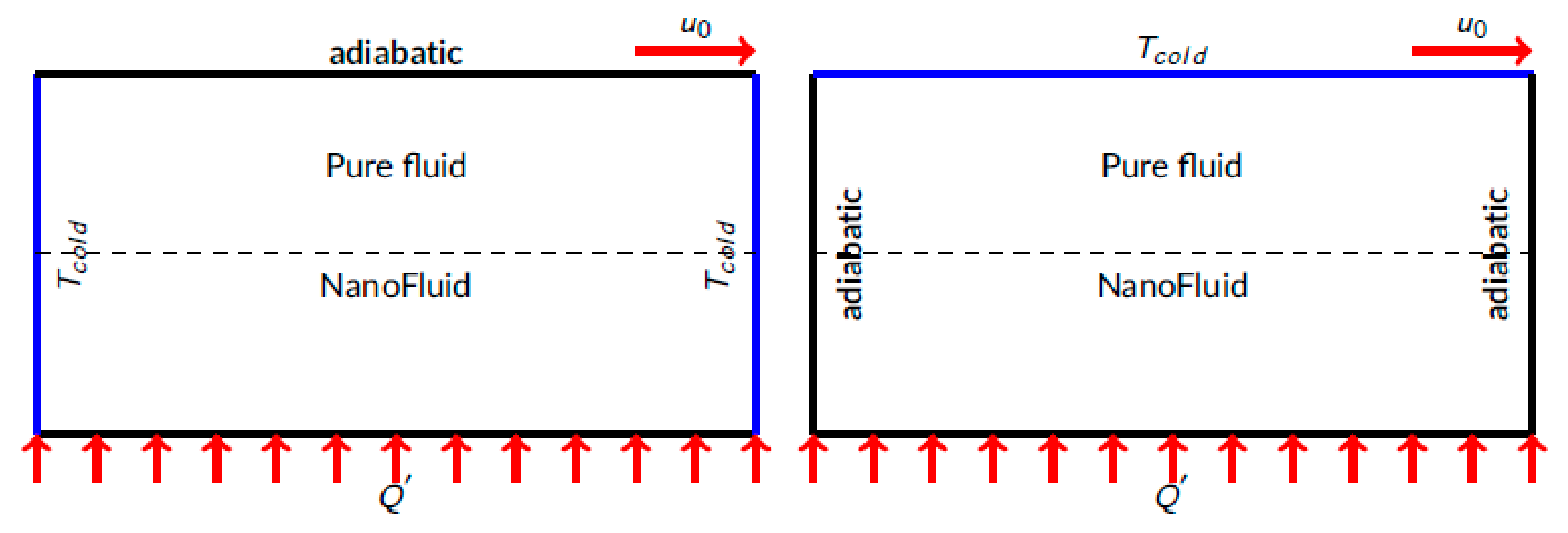
2. Physical Model and Mathematical Formulation

2.1. Physical Model

We consider a rectangular cavity with a movable lid, having a width ( W ) and height ( L = W / 2 ) (see Figure 1). The cavity was filled by two fluid layers separated by a rigid wall with zero thickness. Indeed, the lower region was filled with nanofluid while the upper region was filled with pure fluid. Water was chosen as a working fluid and the solid nanoparticles were Al2O3. Thermophysical properties of fluid and solid have been given by [34] and are represented in Table 1. The bottom of the cavity was exposed to a constant surface heat flow. As a function of cold temperature location, two designs were tested: sidewalls and the top wall of the enclosure. First, a temperature gradient in a perpendicular direction to fluid weight forces (Figure 1 on the left), and second, a temperature gradient in direction of gravity forces due to fluid mass (Figure 1 on the right) were considered.

2.2. Mathematical Formulation

Both fluid layers’ flow was considered to be laminar, two-dimensional, and stable. The continuity, momentum, and energy equations are among the conservative governing equations for this issue. Boussinesq approximation described by Equation (1) has been used, assuming that the thermophysical characteristics of both fluid layers in each area are constant and that the flow is incompressible except in buoyancy terms.
ρ i =   1 β i Δ T ρ 0
wherein i = 1 , for the pure fluid region,
  • i = n f or 2 , for the nanofluid region.
Dimensional Form of Governing Equations for Both Regions
Governing equations for flow can be written as follows [34,35]:
(1). 
Pure Fluid Region:
g 1 x + b 1 y = 0  
g 1 g 1 x + b 1 g 1 y = 1 ρ 1 p 1 x + v 1 2 g 1 x 2 + 2 g 1 y 2
g 1 b 1 x + b 1 b 1 y = 1 ρ 1 p 1 y + v 1 2 b 1 x 2 + 2 b 1 y 2 + β 1 g T 1 T c  
g 1 T 1 x + b 1 T 1 y = α 1 2 T 1 x 2 + 2 T 1 y 2
(2). 
Nanofluid Region:
g 2 x + b 2 y = 0
g 2 g 2 x + b 2 g 2 y = 1 ρ n f p 2 x + v n f 2 b 2 x 2 + 2 b 2 y 2
g 2 b 2 x + b 2 b 2 y = 1 ρ n f p 2 y + v n f 2 b 2 x 2 + 2 b 2 y 2 + β n f g T 2 T c
g 2 T 2 x + b 2 T 2 y = α n f 2 T 2 x 2 + 2 T 2 y 2  
The thermophysical characteristics of nanofluids are obtained using the present rate of nanoparticles φ .
Nanofluid density is determined as follows:
ρ n f = 1 ϕ ρ 2 + ϕ ρ p
In addition, nanofluid thermal diffusivity is calculated by the following formula:
α n f = k n f ρ C p n f  
Hence, the effective capacity of nanofluid ρ C p n f is known, whose following expression is suggested by [39,40,41]:
ρ C p n f = 1 ϕ ρ C p 2 + ϕ ρ C p p  
Moreover, ρ β n f , which corresponds to specific thermal expansion, can be calculated according to the following formula [39,40,41]:
ρ β n f = 1 ϕ ρ β 2 + ϕ ρ β p
The effective thermal conductivity was obtained using the model form of Maxwell-Garnett’s ([36,37,38]):
k n f = k p + 2 k 2 2 ϕ k 2 k p k p + 2 k 2 + ϕ k 2 k p
In this study, we employed the Brinkman model [34], intending to determine effective dynamic viscosity of the nanofluid, which is given by:
μ n f = μ 2 1 ϕ 2.5  
Boundary Conditions [10,34]
Figure 1 depicts the boundary condition of the problem; this can be translated as shown in Table 2.
Dimensionless Form of Governing Equations for Both Regions
Since the mixed convection occurs in the upper region and the natural convection is manifested in the lower region, the dimensionless equations will be different for each layer. Therefore, the choice of an appropriate dimensionless parameter for the transformation of the above-mentioned equation is necessary. We have opted to use the following dimensionless quantities defined by (16).
X = x L ; Y = y L ; θ 1 = T 1 T c Δ T ; θ 2 = T 2 T c Δ T ; Δ T = q L k 2 ; U 1 = g 1 g 0 ; V 1 = b 1 g 0 ; P 1 = p 1 ρ 1 g 0 2 U 2 = g 2 L α 2 ; V 2 = b 2 L α 2 ; P 2 = p 2 L 2 ρ n f α 2 2
Dimensionless Equations for the Pure Fluid Region
U 1 X + V 1 Y = 0  
U 1 U 1 X + V 1 U 1 Y = P 1 X + 1 R e 2 U 1 X 2 + 2 U 1 Y 2  
U 1 V 1 X + V 1 V 1 Y = P 1 Y + 1 R e 2 V 1 X 2 + 2 V 1 Y 2 + R a P r . R e 2 θ 1  
U 1 θ 1 X + V 1 θ 1 Y = 1 P r . R e 2 θ 1 X 2 + 2 θ 1 Y 2  
Dimensionless Equations for the Nanofluid Region
U 2 X + V 2 Y = 0
U 2 U 2 X + V 2 U 2 Y = P 2 X + μ n f ρ n f α 2 1 R e 2 U 2 X 2 + 2 U 2 Y 2  
U 2 V 2 X + V 2 V 2 Y = P 2 Y + μ n f ρ n f α 2 1 R e 2 V 2 X 2 + 2 V 2 Y 2 + β n f β 1 R a P r . Re 2 θ 2
U 2 θ 2 X + V 2 θ 2 Y = α n f α 2 1 P r . R e 2 θ 2 X 2 + 2 θ 2 Y 2
where   R i = G r R e 2 = R a P r . R e 2 .
Dimensionless Boundary Conditions
The boundary conditions in non-dimensional form are shown in Table 3.
Heat transfer Characterization
Local Nusselt Number
N u x = h L k 1  
where h = q T h T c
Average Nusselt Number
N u a v e r g = 0 L N u x
Variation Rate of Heat Transfer:
R = N u a v e r g ( max ) N u a v e r g ( min ) N u a v e r g ( min )

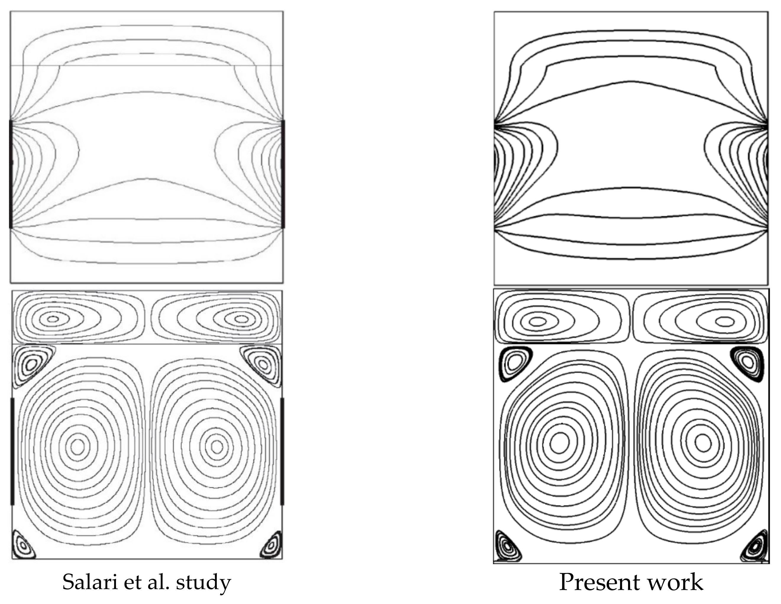
3. Numerical Resolution, Grid Test, and Validation

The physical domain in question has been devised in two blocks, where each block is defined by the set of equations prescribed in the previous section. The dimensionless equations governing each fluid region associated with the appropriate boundary conditions to the problem have been solved numerically using the finite volume method (FVM) defined by [41,42]. In this work, the speed–pressure coupling of each fluid region has been achieved with the SIMPLE algorithm. The convective terms of the two-fluid regions were discretized with the QUICK scheme, while the diffusive terms were approached with the central differences. For the velocity and temperature equations, the algebraic, finite-volume equations are expressed as shown:
a c χ c = a w χ w + a e χ e + a n χ n + a s χ s + b
wherein c , e , w , n , and s signify cell position -- west, east, north, and south faces of the control volume, respectively. In addition, any scalar transit quantity is denoted by χ . It is worth noting that the grid is collocated. The kinematics equation uses a similar expression, with just the central difference employed for discretization at cell P of the control volume. The consecutive over-/under-relaxation approach is used to solve the algebraic equations that arise. Due to the non-linear character of the governing equations, particularly the vorticity equation, successive under-relaxation was adopted. The following expression defines the convergence criterion:
ϵ = j = 1 j = M i = 1 i = N χ n + 1 χ n j = 1 j = M i = 1 i = N χ n + 1
where ϵ is the tolerance and M and N signify the grid-points number in x y coordinates. A convergence criterion was adopted to end the iterative computation. To choose an appropriate grid for our simulation, a mesh test was performed based on the mesh grid of the computational domain, the results of the test are shown in Table 4. We then chose a 120 × 120 grid for the subsequent numerical simulations. The used computational code was tested according to the results presented in the scientific literature. We chose the reference work carried out by [34]. Results of comparison of streamlines and isotherms obtained with the present code and those published by [34] are given in Figure 2. Based on this figure, we can deduce that there is a good qualitative agreement between our results and those of the previous study.

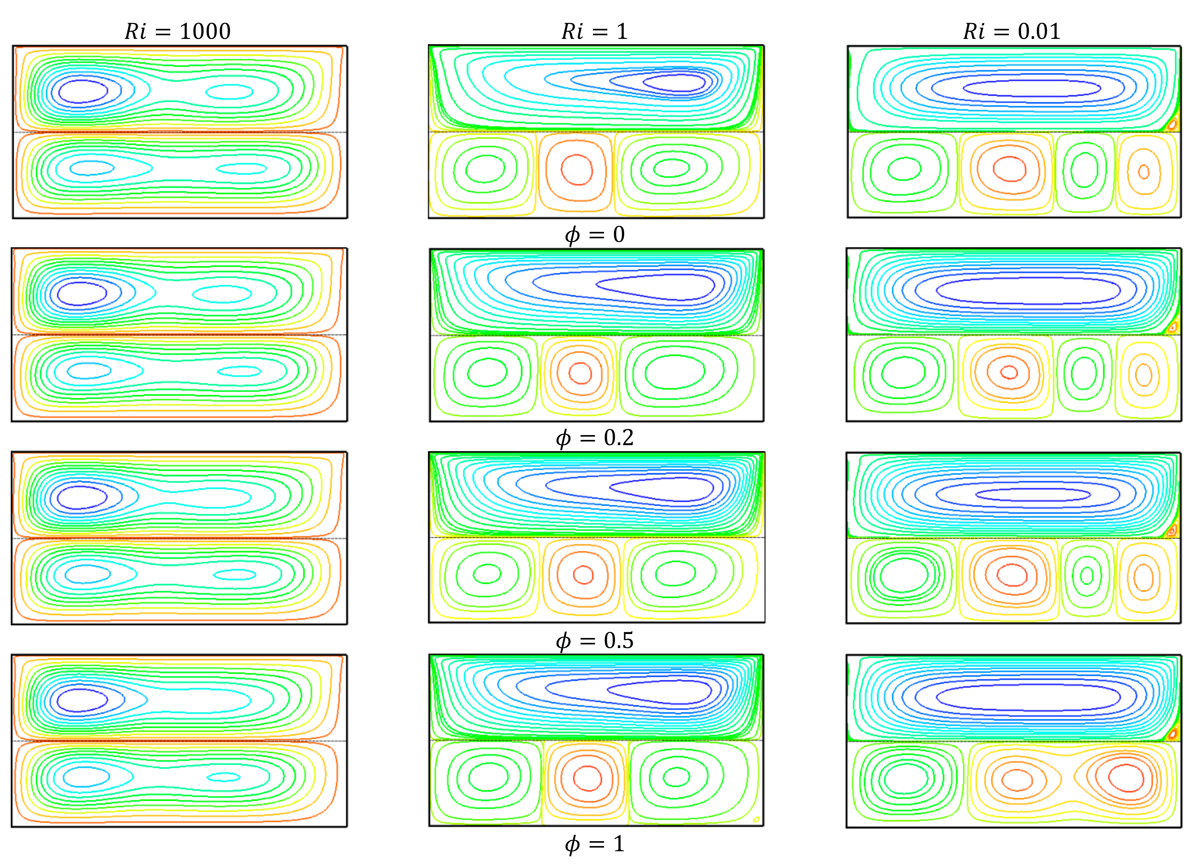
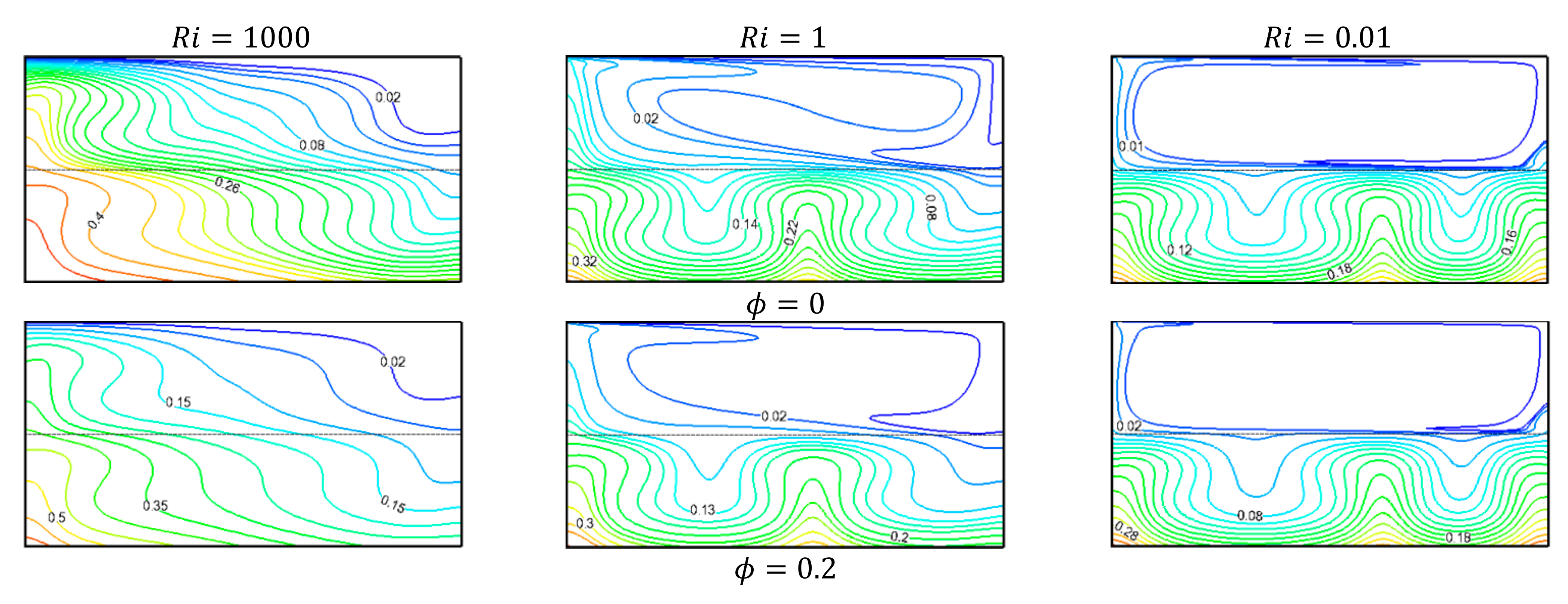
4. Analysis of Findings

This paper aims to determine the effects of nanoparticles’ addition to a base fluid according to two cases when it is subjected to horizontal or vertical thermal gradients. To realize this goal, we have explored a rectangular cavity filled with two fluid layers. The lower layer was sprayed with solid nanoparticles to improve the thermal properties of the medium. For both temperature gradient orientations, a wide range of Richardson ( R i ) numbers was examined, with nanoparticle volume fraction ( ϕ ) varying from 0.0 to 1.

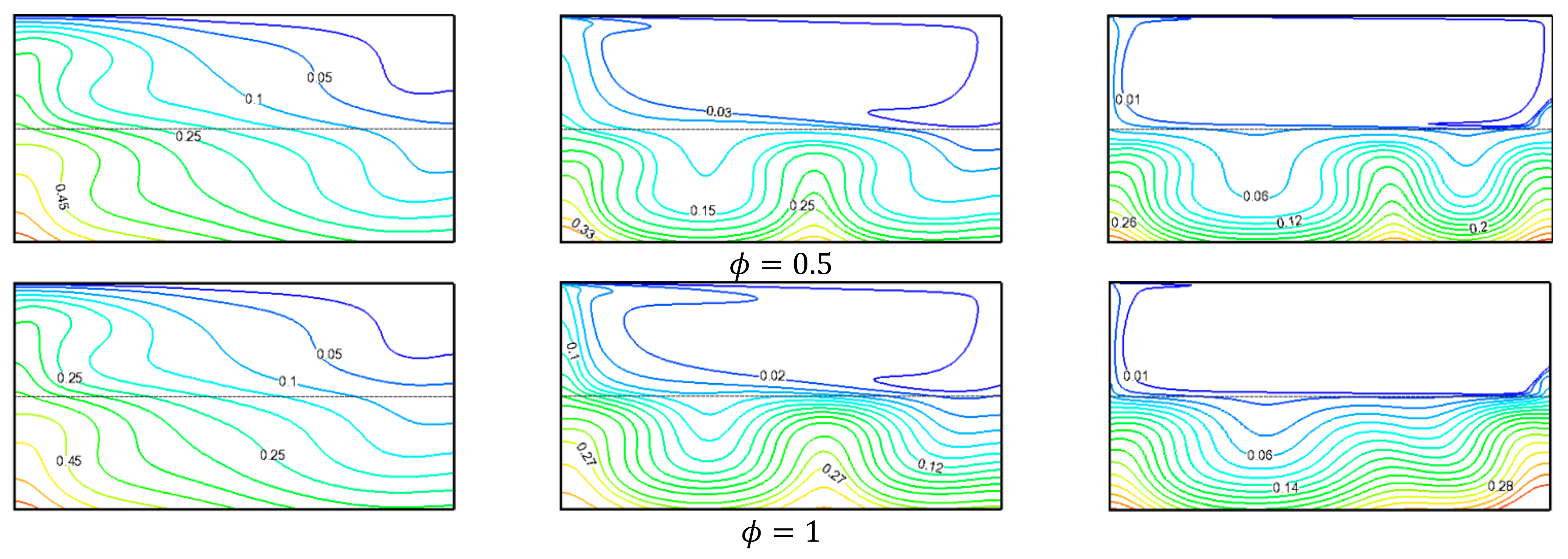
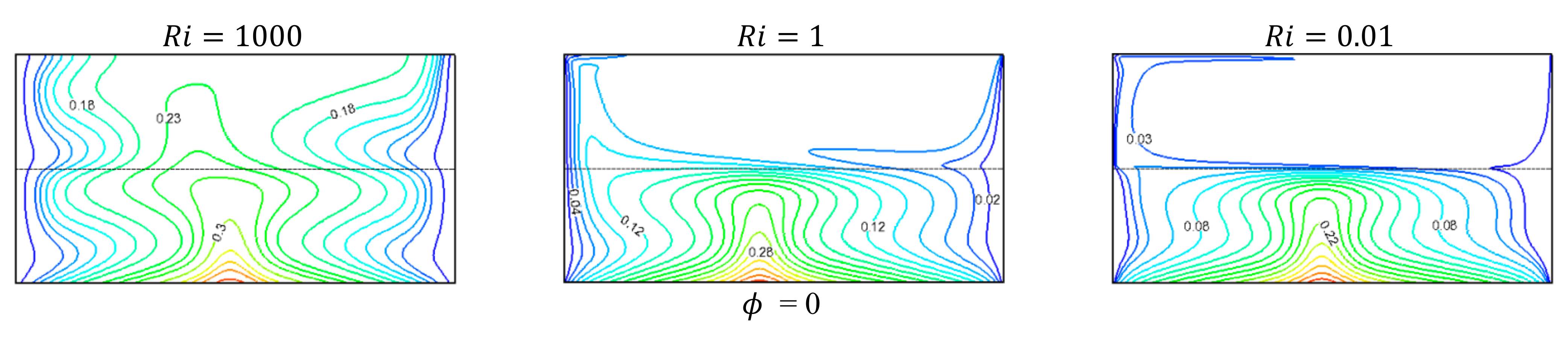
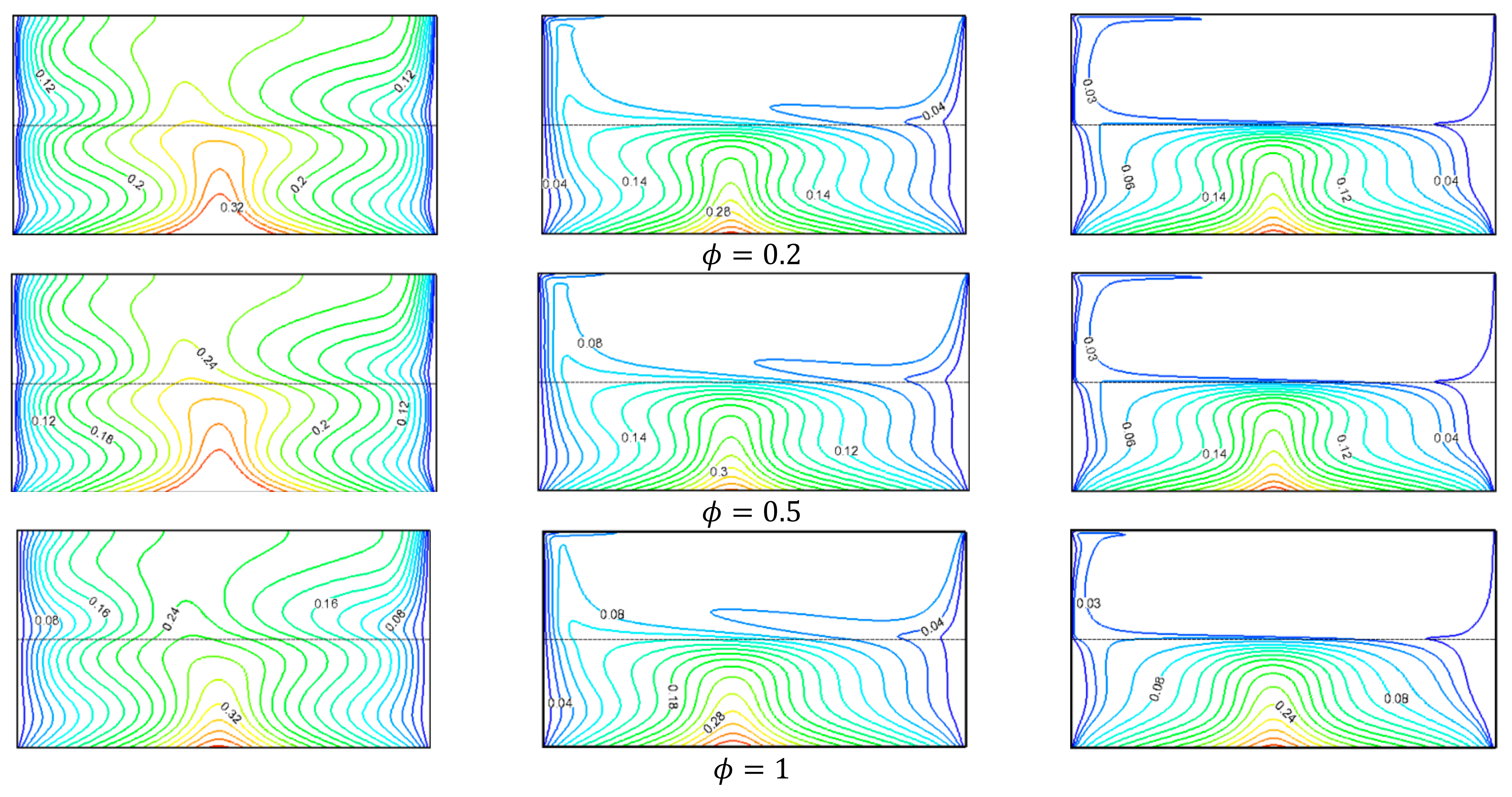
4.1. Vertical Temperature Gradient

For different values of R i and ϕ under a vertical thermal gradient, thermal fields and flow properties of fluid particles in both regions of the cavity have been presented in Figure 3 and Figure 4.
As depicted in Figure 3, the hydrodynamic fields in the chamber are greatly affected by varying the Richardson number; meanwhile, a non-significant effect was observed by changing the volume fraction of nanoparticles.
When R i = 1000 , natural convection effects predominate the formation of flow patterns within the cavity. This is characterized by the development of an ellipse-shaped cell in each fluid region. Dimensions and the design of each convection cell are almost identical. One characteristic of the circulation of fluid particles in each layer is that the cells are counter-rotating, and two small vortices can be distinguished inside these two cells. By contrast, it is worth pointing out that this flow trajectory was not impacted by the increased rate of nanoparticle presence within the lower part of our cavity.
When Richardson’s number is augmented to R i = 1 , there is a strong interaction for the formation of flow pattern between the buoyancy effects induced by the vertical thermal gradient and the kinetic energy effects caused by the moving lid. Indeed, at the upper layer, a single cell was developed, which is characterized by higher intensity, so the convection effects between the fluid particles and the interface become more intense, leading to a greater heat passage at the interface. Thus, the thermal gradients between the heat source located at the cavity bottom and the interface become greater. Consequently, free convection effects tend to occur at the lower layer (nanofluid), which results in a three-cell counter-rotating flow.
Forced convection prevails in the flow scheme configuration when R i = 0.01 , and this is translated by an increase of convection cell numbers appearing in the nanofluid-occupied region. It is also relevant that the addition of solid nanoparticles has a remarkable effect in such cases. The flow pattern changes from a four-cell flow to a three-cell flow at ϕ = 1 .
Corresponding thermal fields to the flow structures of Figure 3 are plotted in Figure 4. When R i = 1000 , the temperature gradient effects were overestimated compared to those caused by the moving lid speed. The isotherms are distributed across the two-cavity regions diagonally. The temperatures at the lower-left corner of the cavity were the highest, and as we moved diagonally towards the upper right corner, the fluid particle temperature dropped. This structure can be termed as a diagonal thermal stratification. This points to the prevalence of conductive regime on the thermal field distribution within each layer. By adding the nanoparticles to the base fluid found in the lower layer, no significant effect was found on the qualitative behavior of isotherm lines.
After the augmentation of the Richardson number value, structures of thermal plume form take the place on the nanofluid layer, a sign of convective regime occurrence. In the upper layer of a cavity, the cold uniform temperature zone extends to cover the whole of this part; here, the regime of forced convection predominates the heat transfer.

4.2. Horizontal Temperature Gradient

In this part, fluid particle trajectories and corresponding thermal fields are discussed for a cavity subjected to a horizontal thermal gradient. Figure 5 shows the streamlines obtained with the second configuration of the temperature gradient for different R i   and different ϕ . For R i = 1000 , a two-cell scheme prevailed in the flow structure in each layer. Increasing the nanoparticle presence rate in the lower layer had almost no effect on the flow structure in both cavity regions. The isotherms were uniformly distributed with a form of thermal plume formed centrally from the heat source penetrating the upper layer (Figure 6). As the velocity of the lid increased (an increase in R i ), the uniform temperature zone at the pure-fluid layer increased and occupied the whole of the upper part of the cavity. In this case, the flow pattern had a two-cell counter-rotating pattern in the nanofluid layer, and a single cell flowed in the pure fluid layer.

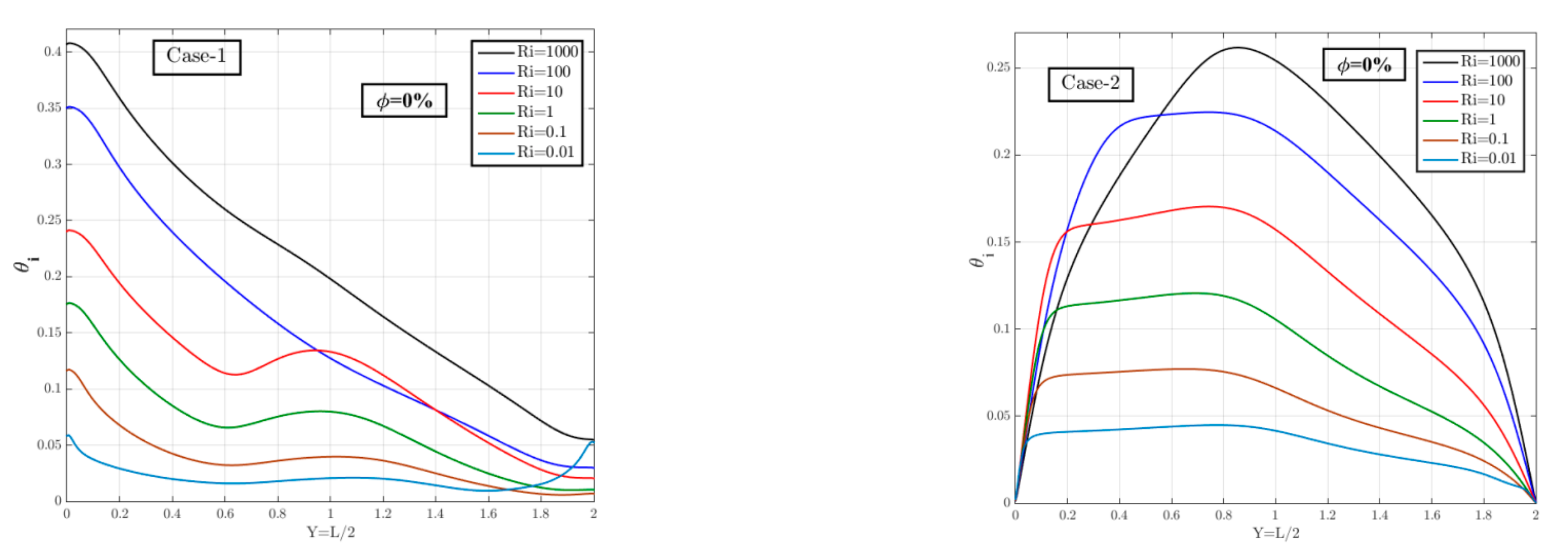
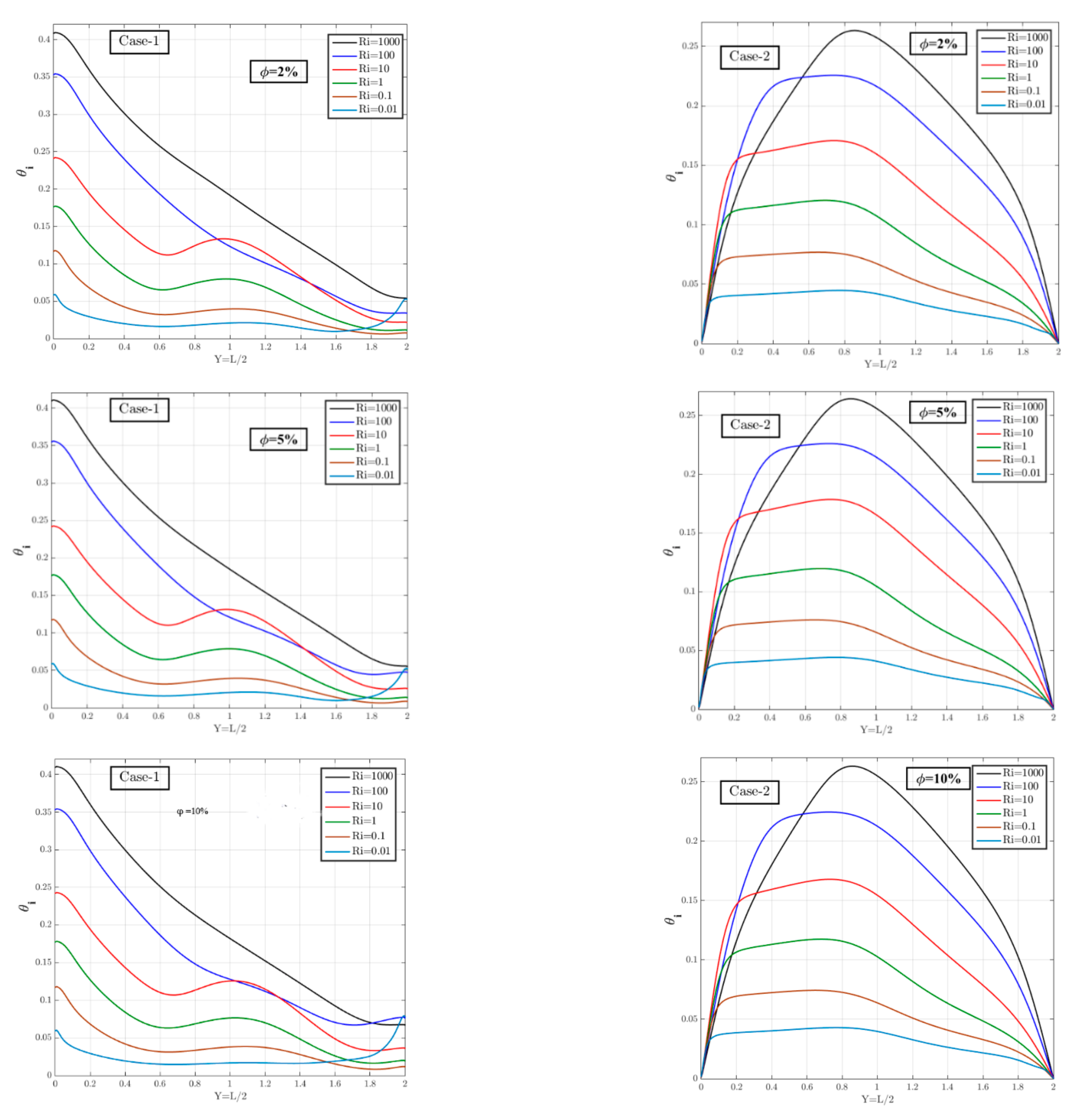
4.3. Temperature Evolution at the Interface

To characterize the thermal behavior of the interface between both fluid layers, the temperature evolution at this location has been presented as a function of the control parameters considered for both thermal gradient orientation cases (see Figure 7). It is clear from this figure that increasing the Richardson number leads to an increase in the interface temperature in both cases of temperature gradient orientation. This remark is valid whatever the value of the nanoparticles’ volume fraction. It is also important to note that in the case of vertical thermal gradients, the Richardson number effect is more noticeable on the right side of the cavity.

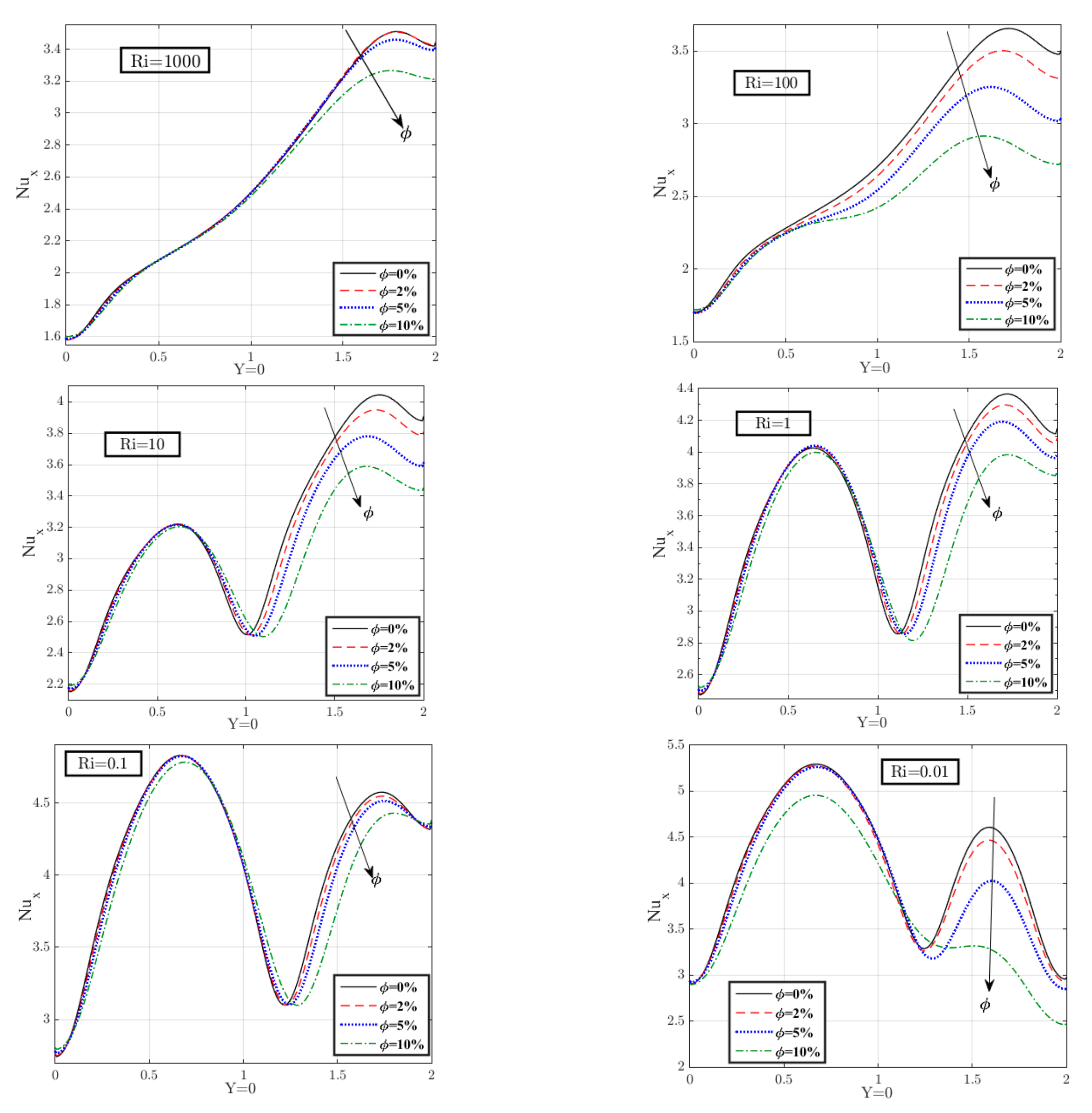
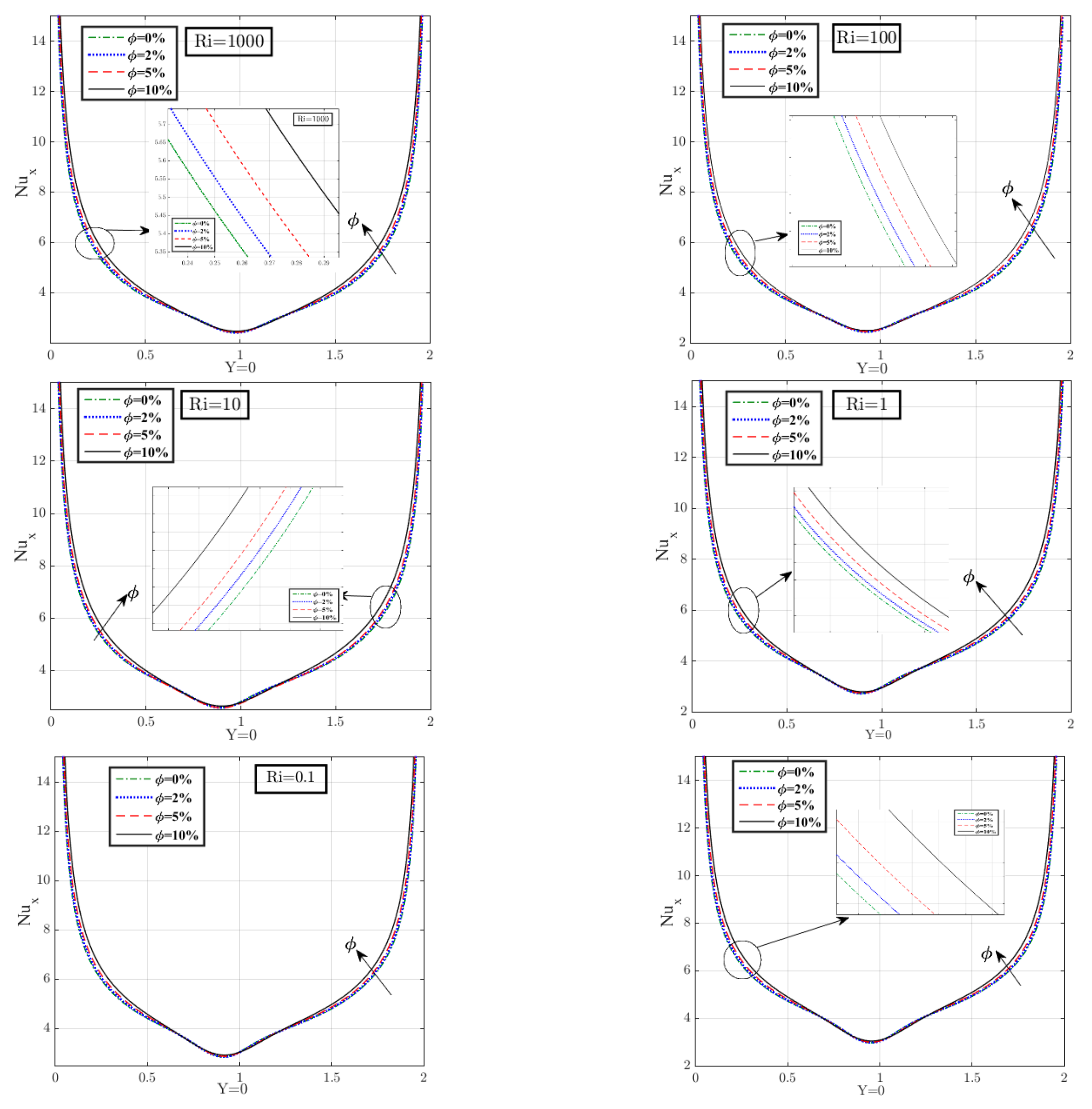
4.4. Local Heat Transfer Rate

Heat transfer rate in the cavity is evaluated by the local Nusselt number recorded along the hot bottom wall. The impact of percent addition of nanoparticles in the lower layer is shown in Figure 8, for each value of Richardson number for case 1. It is important to note that the mobile cover flows from left to right. For a high value of Richardson ( R i = 1000 ), there was a low speed of the mobile cover of the cavity, which generated a low circulation of the fluid, and ϕ effects were low since the conduction regime predominated the heat transfer.
When going to R i = 100 , we observed that ϕ effects were more significant. In these two cases, we saw an increasing evolution of the local Nusselt curve from left to right. This is a sign that the heat transfer is mainly done on the right side of the cavity. As R i takes lower values, forced convection effects predominate the flow and heat transfer in an upper layer, which helps the fluid movement in the lower part and the prevailing convective regime therein. This was reflected by the appearance of thermal plumes in the isothermal lines and local Nusselt curves with peaks. It is also interesting to note that when the temperature gradients are parallel to the gravity forces, the addition of nanoparticles to the lower layer contributes negatively to the improvement of the heat transfer rate. This is due to the increase in gravity forces due to the fluid weight, which are predominant in front of the buoyancy forces of the system.
Local Nusselt evolution curves are presented in Figure 9 depicting when the temperature gradients are perpendicular to the gravity forces. As shown in this figure, local Nusselt curves exhibit parabolic shapes with minimal values around the cavity center. In that case, the ϕ effects are weak regardless of the Richardson number value. Based on this figure, it was found that adding solid particles to the lower fluid improves the heat transfer rate in the cavity.

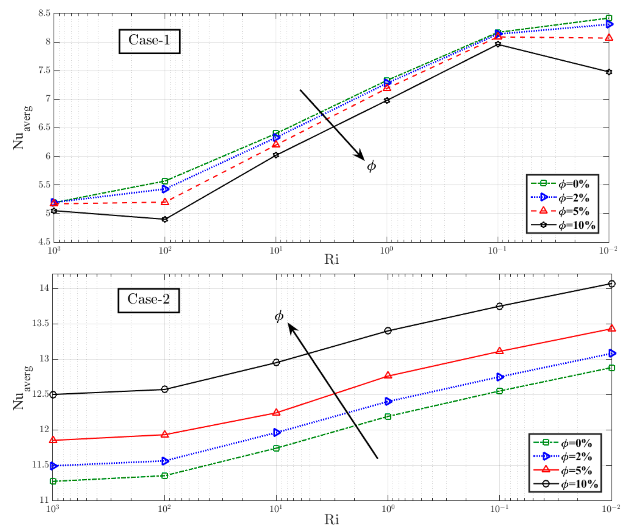
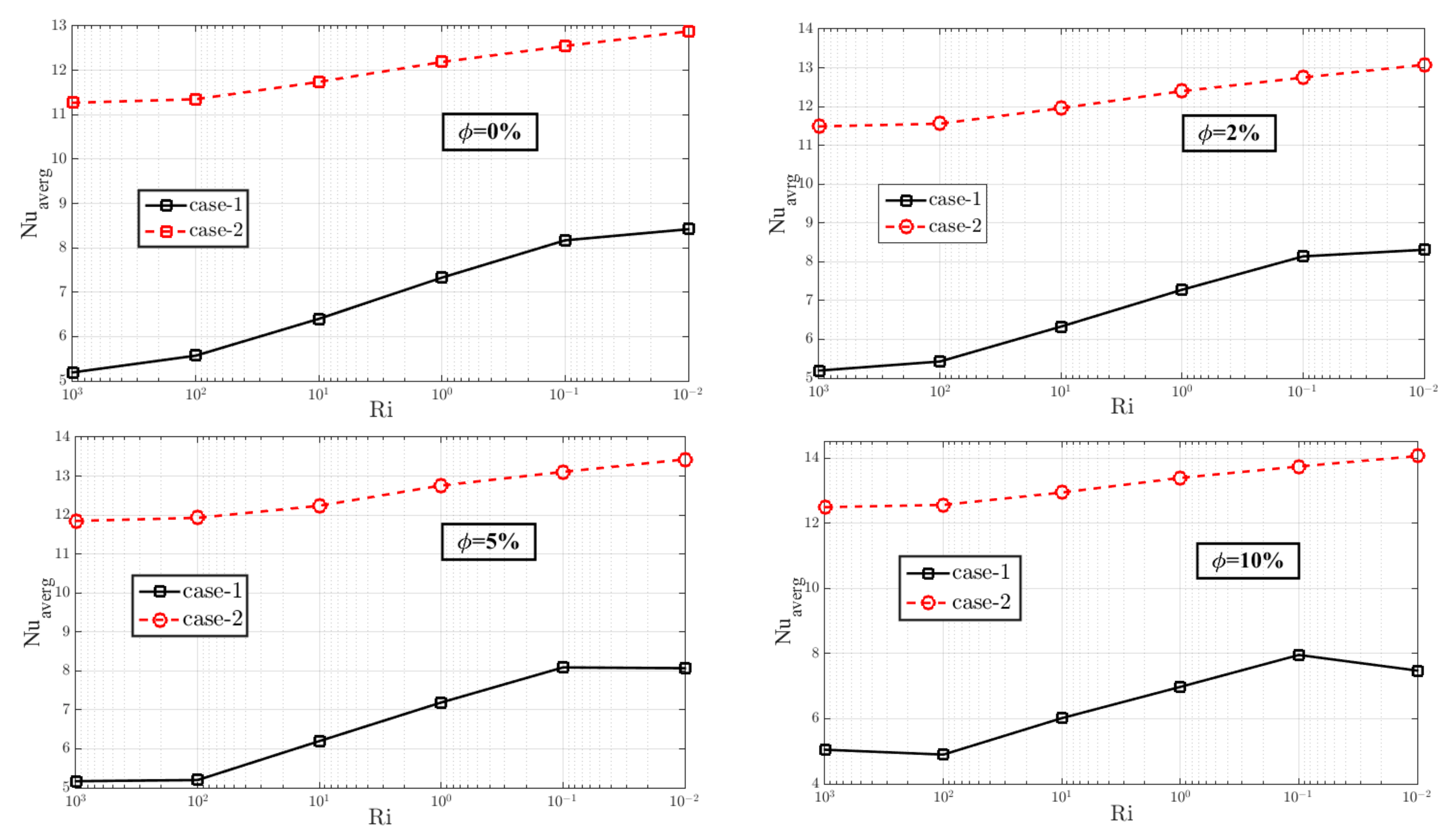
4.5. Overall Heat Transfer Rate

Global heat transfer is evaluated here by calculating the average Nusselt number at the cavity bottom. The results are presented in Figure 10 and Figure 11 according to the different parameters taken in this paper. Figure 10 displays the decreasing evolution of heat transfer rate as a function of Richardson number in the two cases of thermal gradient orientation. In a case where the thermal gradient is parallel to the gravity forces (case 1), global heat exchange decreases with the increase in ϕ value. On the opposite side, we notice that for a gradient perpendicular to the gravity forces (case 2), the heat transfer rate grows with an increasing percentage of nanoparticles. Figure 11 shows the comparison between the average Nusselt recorded with case 1 and case 2, as a function of R i and ϕ . In all these cases, it was found that the average N u is higher when the configuration of a perpendicular gradient to the gravity forces (case 2) is used.
To determine the variation rate of heat transfer in all cases treated, we opted to present the average N u variation rate defined by Equation (28). Figure 12 and Figure 13 show histograms of this variation rate. In these figures, each value of the Reynolds number is relative to a corresponding Richardson number with ( R i = R a / ( P r . R e 2 ), where R a = 10 5 and P r = 6.81 ). Figure 12, relative to the variation rate of average N u for case 1, reveals that as ϕ value increases, R i ’s contribution to the rise in average N u goes from 67.17% to 48.11%. On the other hand, it was found that the solid volume fraction contributes to the reduction of heat transfer rate with a moderate rate ranging from 2.73% to 12.09%. Another register, Figure 13, shows the average N u variation rate in case 2. This figure states that the two parameters R i and ϕ give heat exchange rate moderate percentages.

5. Conclusions

In this work a computational study based on the finite volume method was conducted to investigate the impact of the temperature gradient orientation on mixed convection induced in a cavity separated by a stiff wall of zero thickness and heated from below filled with two superposed layers: pure fluid and nanofluid. By looking at the various parameters, namely the Richardson number, the volume fraction of the solid, and the configuration of the thermal gradient, we were able to make the following findings:
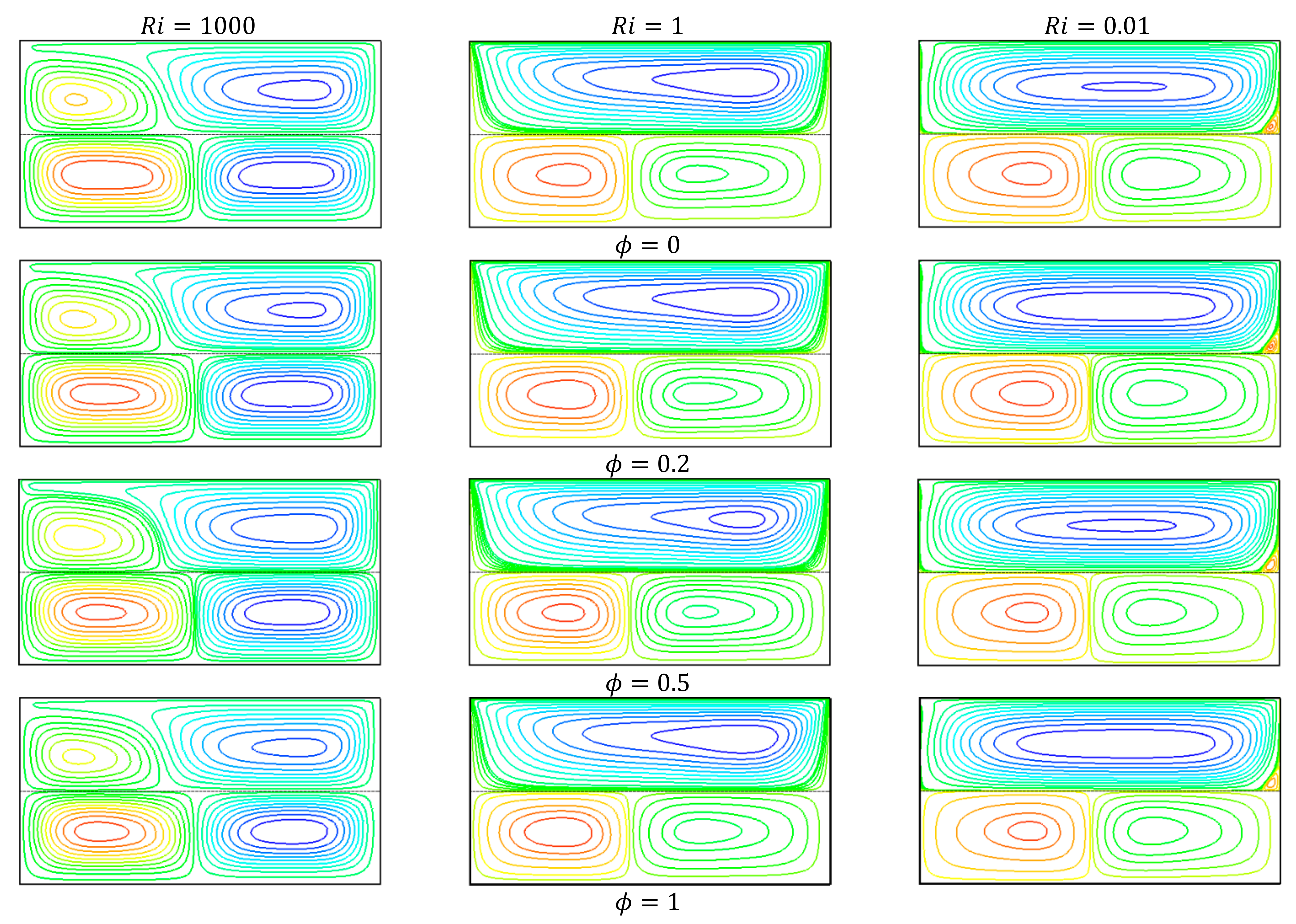
  • Both flow and thermal structure have been affected by Richardson number and temperature gradient orientation and insignificantly affected by the ϕ parameter.
  • Natural convection effects predominate the formation of flow pattern, and the temperature gradient effects are overestimated when Richardson number is 1000 or more.
  • Heat transfer rate can be improved by perpendicular orientation to gravity forces of thermal gradient
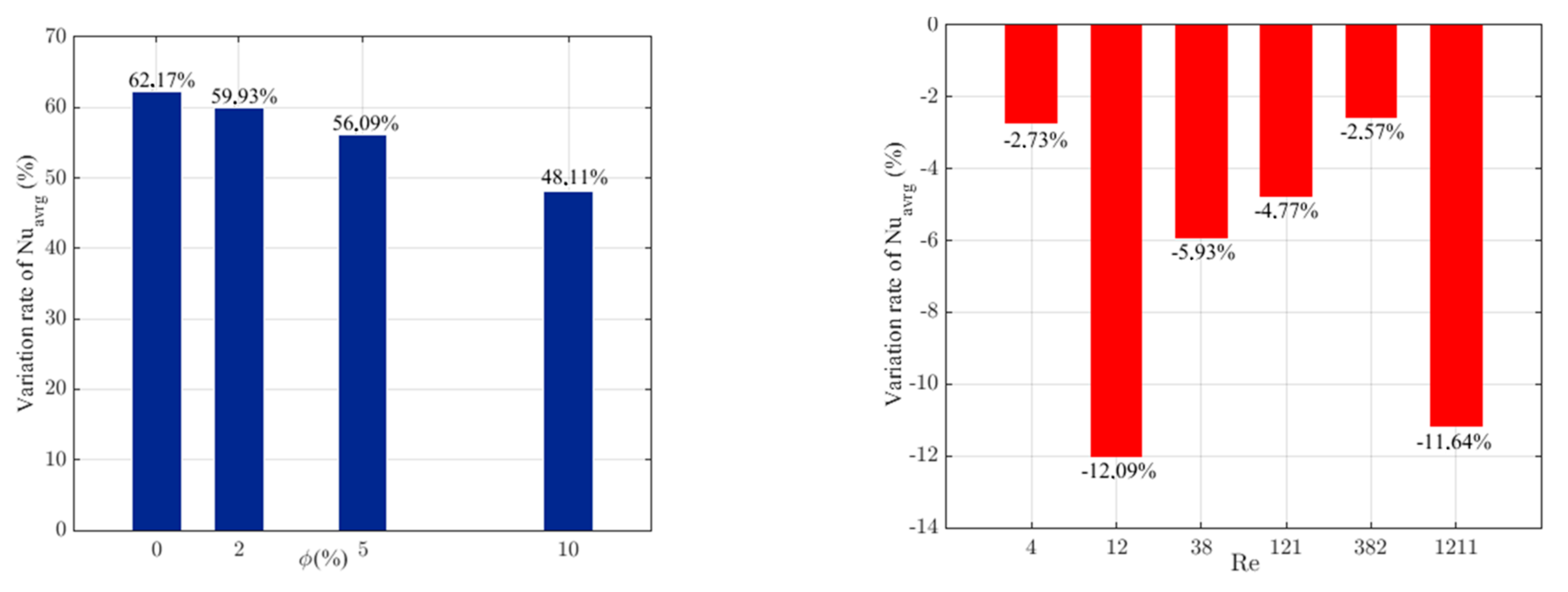
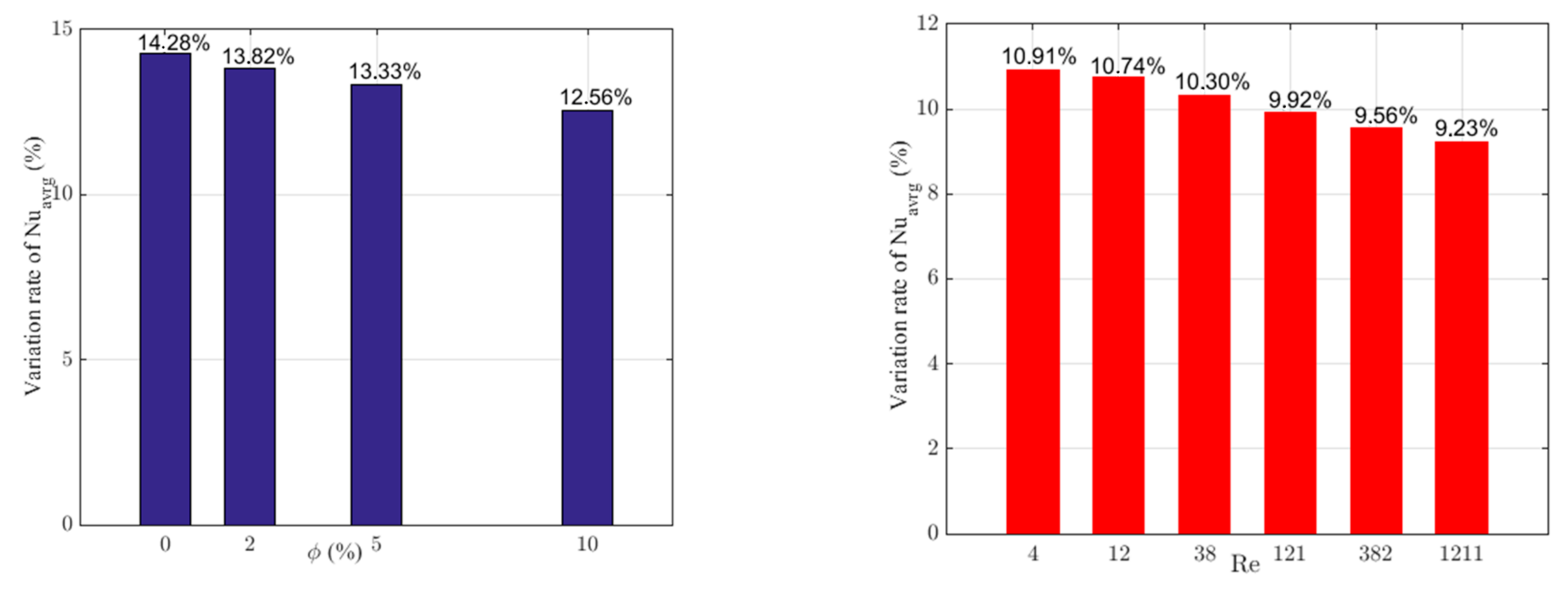
  • The rate of change of heat transfer is largely affected by the Richardson number and ϕ in case 1, and smaller variation with case 2 has been recorded.
  • In the case of a thermal gradient perpendicular to the gravity forces (case 2), overall heat transfer is improved with increasing solid volume fraction, but a significant decrease was recorded when the thermal gradient is parallel to the gravity forces (case 2).
Different combinations of hybrid nanofluid could be explored in the future to obtain heat transmission rates for specific challenges while considering additional physical surroundings and unsolved industrial problems. It is possible to introduce new boundary conditions to simulate the reality by linking this to the engineering and industrial field. In addition, the numerical method could be changed for more recent numerical simulation techniques.

Author Contributions

Conceptualization, A.K., W.J. and M.R.E.; methodology, A.K., W.J. and M.R.E.; software, A.K., A.A. (Aissa Abderrahmane), W.J. and M.R.E.; validation, A.K., W.J., S.M.H., K.S.N., A.A. (Abdel-Haleem Abdel-Aty), I.S.Y. and M.R.E.; formal analysis, A.K., A.A. (Aissa Abderrahmane), W.J. and M.R.E.; investigation, A.K., A.A. (Aissa Abderrahmane), W.J., A.A. (Abdel-Haleem Abdel-Aty), I.S.Y. and M.R.E.; resources, A.K., W.J., K.S.N. and M.R.E.; data curation, A.K., W.J., S.M.H., K.S.N. and M.R.E.; writing—original draft preparation, A.K., W.J., S.M.H., K.S.N., A.A. (Aissa Abderrahmane), I.S.Y. and M.R.E.; writing—review and editing, A.K., W.J., S.M.H., K.S.N., A.A. (Abdel-Haleem Abdel-Aty), I.S.Y. and M.R.E.; visualization, A.K., W.J., S.M.H., K.S.N., A.A. (Aissa Abderrahmane), I.S.Y. and M.R.E.; funding acquisition, I.S.Y. All authors have read and agreed to the published version of the manuscript.

Funding

This research was funded by the Deanship of Scientific Research at King Khalid University grant number R.G.P.2/110/41 and the Deputyship for Research & Innovation, Ministry of Education, in Saudi Arabia, through the project number: (IFP-KKU-2020/10).

Institutional Review Board Statement

Not Applicable.

Informed Consent Statement

Not Applicable.

Data Availability Statement

The results of this study are available only within the paper to support the data.

Acknowledgments

The authors express their appreciation to the Deanship of Scientific Research at King Khalid University for funding this work through the research groups program under Grant No. R.G.P.2/110/41. Also, the authors extend their appreciation to the Deputyship for Research & Innovation, Ministry of Education, in Saudi Arabia for funding this research work through the project number: (IFP-KKU-2020/10).

Conflicts of Interest

Concerning this manuscript, we have no conflict of interest.

Nomenclature

C p specific heat J   K 1 Greek symbols
g ,   b velocity components ms 1 α thermal diffusivity m 2 s 1
G r Grashof number β thermal expansion coefficient
h heat flux W θ dimensionless temperature
k thermal conductance Wm 1 K 1 μ dynamic viscosity kgm 1 s 1
L height m ρ density kgm 3  
p dimensional pressure Pa ϕ nanoparticle size
P dimensionless pressure v kinematic viscosity m 2 s 1  
P r Prandtl number χ scalar transit quantity
q ˙ thermal heat flux   W · m 2 Subscripts
R a Rayleigh number 0 initial case
R e Reynolds number 1 pure fluid region
R i Richardson number 2 nanofluid region
T temperature K c ,   h cold and hot side
U ,   V dimensionless velocity components n f nanofluid
N u Nusselt number p solid nanoparticles
W width m a v e r g average
c cell position --
e , w , n , s west, east, north, and south faces of the control volume--

References

  1. Richter, F.M.; McKenzie, D.P. On some consequences and possible causes of layered mantle convection. J. Geophys. Res. 1981, 86, 6133–6142. [Google Scholar] [CrossRef]
  2. Renardy, Y.; Joseph, D.D. Oscillatory instability in a Bénard problem of two fluids. Phys. Fluids 1985, 28, 788–793. [Google Scholar] [CrossRef]
  3. Cserepes, L.; Rabinowicz, M. Gravity and convection in a two-layer mantle. Earth Planet. Sci. Lett. 1985, 76, 193–207. [Google Scholar] [CrossRef]
  4. Someya, S.; Munakata, T.; Nishio, M.; Okamoto, K. Flow observation in two immiscible liquid layers subject to a horizontal temperature gradient. J. Cryst. Growth 2002, 235, 626–632. [Google Scholar] [CrossRef]
  5. Liu, Q.S.; Roux, B.; Velarde, M.G. Thermocapillary convection in two-layer systems. Int. J. Heat Mass Transf. 1998, 41, 1499–1511. [Google Scholar] [CrossRef]
  6. Doi, T.; Koster, J.N. Thermocapillary convection in two immiscible liquid layers with free surface. Phys. Fluids A 1992, 5, 1914–1927. [Google Scholar] [CrossRef]
  7. Langlois, W.E. Buoyancy-driven flows in crystal-growth melts. Annu. Rev. Fluid Mech. 1985, 17, 191–215. [Google Scholar] [CrossRef]
  8. Oztop, H.F.; Varol, Y.; Koca, A. Natural convection in a vertically divided square enclosure by a solid partition into air and water regions. Int. J. Heat Mass Transf. 2009, 52, 5909–5921. [Google Scholar] [CrossRef]
  9. Selimefendigil, F.; Öztop, H.F. Conjugate natural convection in a cavity with a conductive partition and filled with different nanofluids on different sides of the partition. J. Mol. Liq. 2016, 216, 67–77. [Google Scholar] [CrossRef]
  10. Koulali, A.; Meziani, B.; Sadaoui, D.; Sahi, A.; Adnani, M. Numerical investigation of conjugate heat transfer in the presence of two fluid separated by a rigid wall. Heat Transf. 2020, 49, 4981–5001. [Google Scholar] [CrossRef]
  11. Villers, D.; Platten, J.K. Thermal convection in superposed immiscible liquid layers. Appl. Sci. Res. 1988, 45, 145–152. [Google Scholar] [CrossRef]
  12. Prakash, A.; Koster, J.; Hill, M. Natural and thermocapillary convection in multiple liquid layers. In Proceedings of the 31st Aerospace Sciences Meeting, Reno, NV, USA, 11 January 1993–14 January 1993. [Google Scholar] [CrossRef]
  13. Koster, J.N.; Nguyen, K.Y. Steady natural convection in a double layer of immiscible liquids with density inversion. Int. J. Heat Mass Transf. 1996, 39, 467–478. [Google Scholar] [CrossRef]
  14. Koulali, A.; Sahi, A.; Meziani, B.; Aissa, A.; Sadaoui, D.; Ali, H.M. CFD analysis of natural convection between two superposed fluids: Role of corrugated bottoms. Chem. Eng. Commun. 2021. [Google Scholar] [CrossRef]
  15. Oueslati, F.S.; Bennacer, R.; Sammouda, H.; El Ganaoui, M. Analytical and numerical solutions for natural convection in a shallow cavity filled with two immiscible fluids: Shear stress action. Numer. Heat Transf. Part A Appl. 2012, 62, 605–623. [Google Scholar] [CrossRef]
  16. Oueslati, F.S.; Bennacer, R.; El Ganaoui, M. Analytical and numerical solution to the convection problem in a shallow cavity filled with two immiscible superposed fluids. Int. J. Therm. Sci. 2015, 90, 303–310. [Google Scholar] [CrossRef]
  17. Chamkha, A.J.; Umavathi, J.C.; Mateen, A. Oscillatory Flow and Heat Transfer in Two Immiscible Fluids. Int. J. Fluid Mech. Res. 2004, 31, 13–36. [Google Scholar] [CrossRef] [Green Version]
  18. Hisham, M.D.; Rauf, A.; Vieru, D.; Awan, A.U. Analytical and semi-analytical solutions to flows of two immiscible Maxwell fluids between moving plates. Chin. J. Phys. 2018, 56, 3020–3032. [Google Scholar] [CrossRef]
  19. Umavathi, J.C.; Shekar, M. Mixed convective flow of immiscible fluids in a vertical corrugated channel with traveling thermal waves. J. King Saud Univ.-Eng. Sci. 2014, 26, 49–68. [Google Scholar] [CrossRef] [Green Version]
  20. Stamenković, Ž.; Nikodijević, D.; Milenković, D.; Blagojević, B.; Nikodijevic, J. Flow and heat transfer of two immiscible fluids in the presence of uniform inclined magnetic field. Math. Probl. Eng. 2011, 2011. [Google Scholar] [CrossRef]
  21. Qu, X.; Fang, D.; Qi, X. Direct contact heat transfer enhancement between two stratified immiscible fluids by artificial interface oscillations. Int. J. Heat Mass Transf. 2019, 138, 226–234. [Google Scholar] [CrossRef]
  22. Sarris, I.; Kakarantzas, S.; Grecos, A.; Vlachos, N. MHD natural convection in a laterally and volumetrically heated square cavity. Int. J. Heat Mass Transf. 2005, 48, 3443–3453. [Google Scholar] [CrossRef]
  23. Kakarantzas, S.; Sarris, I.; Grecos, A.; Vlachos, N. Magnetohydrodynamic natural convection in a vertical cylindrical cavity with sinusoidal upper wall temperature. Int. J. Heat Mass Transf. 2009, 52, 250–259. [Google Scholar] [CrossRef]
  24. Benos, L.T.; Kakarantzas, S.; Sarris, I.; Grecos, A.; Vlachos, N. Analytical and numerical study of MHD natural convection in a horizontal shallow cavity with heat generation. Int. J. Heat Mass Transf. 2014, 75, 19–30. [Google Scholar] [CrossRef]
  25. Benos, L.; Sarris, I. Analytical study of the magnetohydrodynamic natural convection of a nanofluid filled horizontal shallow cavity with internal heat generation. Int. J. Heat Mass Transf. 2019, 130, 862–873. [Google Scholar] [CrossRef]
  26. Hemmat Esfe, M.; Saedodin, S.; Hasani Malekshah, E.; Babaie, A.; Rostamian, H. Mixed Convection Inside Lid-Driven Cavities Filled with Nanofluids: A Comprehensive Review; Springer International Publishing: Cham, Switzerland, 2019; Volume 135, ISBN 0123456789. [Google Scholar]
  27. Selimefendigil, F. Mixed convection in a lid-driven cavity filled with single and multiple-walled carbon nanotubes nanofluid having an inner elliptic obstacle. Propuls. Power Res. 2019, 8, 128–137. [Google Scholar] [CrossRef]
  28. Taamneh, Y.; Bataineh, K. Mixed convection heat transfer in a square lid-driven cavity filled with Al2O3-Water Nanofluid. Stroj. Vestn./J. Mech. Eng. 2017, 63, 383–393. [Google Scholar] [CrossRef] [Green Version]
  29. Ali, I.R.; Alsabery, A.I.; Bakar, N.A.; Roslan, R. Mixed convection in a double lid-driven cavity filled with hybrid nanofluid by using finite volume method. Symmetry 2020, 12, 1–1977. [Google Scholar] [CrossRef]
  30. Sheremet, M.A.; Pop, I. Mixed convection in a chamber saturated with MWCNT-Fe3O4/water hybrid nanofluid under the upper wall velocity modulation. Eur. Phys. J. Plus 2021, 123. [Google Scholar] [CrossRef]
  31. Alotaibi, H.; Eid, M.R. Thermal analysis of 3D electromagnetic radiative nanofluid flow with suction/blowing: Darcy–Forchheimer scheme. Micromachines 2021, 12, 1395. [Google Scholar] [CrossRef]
  32. Benos, L.T.; Polychronopoulos, N.D.; Mahabaleshwar, U.S.; Lorenzini, G.; Sarris, I.E. Thermal and flow investigation of MHD natural convection in a nanofluid-saturated porous enclosure: An asymptotic analysis. J. Therm. Anal. Calorim. 2021, 143, 751–765. [Google Scholar] [CrossRef]
  33. Alsabery, A.I. Natural Convection Flow of a Nanofluid in an Inclined Square Enclosure Partially Filled with a Porous Medium. Sci. Rep. 2017, 7, 2357. [Google Scholar] [CrossRef]
  34. Salari, M.; Malekshah, E.H.; Malekshah, M.H. Natural convection in a rectangular enclosure filled by two immiscible fluids of air and Al2O3-water nanofluid heated partially from side walls. Alex. Eng. J. 2018, 57, 1401–1412. [Google Scholar] [CrossRef]
  35. Koulali, A.; Meziani, B.; Sadaoui, D.; Adnani, M.; Sahi, A. Mixed Convection in Lid-Driven “T” Shallow Cavity Heated From Bottom and Filled by Two Immiscible Fluids of Air and Al2O3-Water Nanofluid. MATEC Web Conf. 2020, 330, 01008. [Google Scholar] [CrossRef]
  36. Abd Elmaboud, Y. Two layers of immiscible fluids in a vertical semi-corrugated channel with heat transfer: Impact of nanoparticles. Results Phys. 2018, 9, 1643–1655. [Google Scholar] [CrossRef]
  37. Al-Srayyih, B.M.; Gao, S.; Hussain, S.H. Natural convection flow of a hybrid nanofluid in a square enclosure partially filled with a porous medium using a thermal non-equilibrium model. Phys. Fluids 2019, 31, 043609. [Google Scholar] [CrossRef]
  38. Niazi, M.D.K.; Xu, H. Modelling two-layer nanofluid flow in a micro-channel with electro-osmotic effects by means of Buongiorno ’ s model. Appl. Math. Mech. 2020, 41, 83–104. [Google Scholar] [CrossRef]
  39. Sarkar, S.; Ganguly, S.; Dalal, A. Buoyancy driven flow and heat transfer of nanofluids past a square cylinder in vertically upward flow. Int. J. Heat Mass Transf. 2013, 59, 433–450. [Google Scholar] [CrossRef]
  40. Khorasanizadeh, H.; Nikfar, M.; Amani, J. Entropy generation of Cu-water nanofluid mixed convection in a cavity. Eur. J. Mech. B/Fluids 2013, 37, 143–152. [Google Scholar] [CrossRef]
  41. Abu-Nada, E.; Chamkha, A.J. Mixed convection flow in a lid-driven inclined square enclosure filled with a nanofluid. Eur. J. Mech. B/Fluids 2010, 29, 472–482. [Google Scholar] [CrossRef]
  42. Patankar, S.V. Numerical Heat Transfer and Fluid Flow; CRC Press: Boca Raton, FL, USA, 1980. [Google Scholar]
Figure 1. Physical Model and Boundary Conditions (Case 1 in the (Right), Case 2 in the (Left)).
Coatings 11 01481 g001
Figure 2. Comparison between our result and those presented by Salari et al. [34].
Coatings 11 01481 g002
Figure 3. Streamlines for different values of R i and φ with case 1.
Coatings 11 01481 g003
Figure 4. Isotherms for different values of R i and ϕ with case 1.
Coatings 11 01481 g004aCoatings 11 01481 g004b
Figure 5. Streamlines for different values of R i and φ for case 2.
Coatings 11 01481 g005
Figure 6. Isotherms for different values of Ri and ϕ for case 2.
Coatings 11 01481 g006aCoatings 11 01481 g006b
Figure 7. Effect of R i   on dimensionless temperature evolution at the interface, on the left for case 1 and on the right for case 2.
Coatings 11 01481 g007aCoatings 11 01481 g007b
Figure 8. Effect of φ on N u x for different R i using case 1 configuration.
Coatings 11 01481 g008
Figure 9. Effect of φ on N u x for different R i using case 2 configuration.
Coatings 11 01481 g009
Figure 10. Average Nusselt number vs. Richardson number for various ϕ in both cases (1 and 2).
Coatings 11 01481 g010
Figure 11. Configuration effect on N u a v e r g for with various R i and different ϕ .
Coatings 11 01481 g011
Figure 12. Effect of ϕ in the left and R e in the right on variation rate of N u a v r g with case 1.
Coatings 11 01481 g012
Figure 13. Effect of ϕ in the left and R e   in the right on variation rate of N u a v r g with case 2.
Coatings 11 01481 g013
Table 1. Thermophysical characteristics of H2O and solid particles [34].
ρ C p k β
Pure Fluid997.141790.61321 × 10−5
Al2O33970765400.85 × 10−5
Table 2. Dimensional Boundary Conditions.
BoundaryCase 1Case 2
At the Cavity Bottom T y = q , g 2 = b 2 = 0 T y = q , g 2 = b 2 = 0
At Side-Walls of Cavity T 1 x = T 2 x = 0 , g 2 = b 2 = g 1 = b 1 = 0 T 1 = T 2 = T c , g 2 = b 2 = g 1 = b 1 = 0
At the Upper of Cavity T 1 = T c ;   g 1 = g 0   ;   b 1 = 0 T 1 y = 0 , g 1 = g 0 ;   b 1 = 0
At the Fluid-Nanofluid Interface k 1 T 1 y = k 2 T 2 y ; T 1 = T 2 ; g 1 = b 2 = g 1 = b 2 = 0
Table 3. Dimensionless Boundary Conditions.
BoundaryCase 1Case 2
At the Cavity Bottom θ 1 Y = 1 , U 2 = V 2 = 0 θ 1 Y = 1 , U 2 = V 2 = 0
At Side-Walls of Cavity θ 1 X = θ 2 X = 0 , U 2 = V 2 = U 1 = V 1 = 0 θ 1 = θ 2 = 0 , U 2 = V 2 = U 1 = V 1 = 0
At the Upper of Cavity θ 1 = 0 ;   U 1 = 1 ; V 1 = 0 θ 1 Y = 0 , U 1 = 1 ; V 1 = 0
At the Fluid-Nanofluid Interface θ 1 Y = k n f k 1 θ 2 Y ; θ 1 = θ 2 ; U 1 = U 2 = V 1 = V 2 = 0
Table 4. Sensitivity of the mean Nusselt number to mesh size for R i = 0.01 , ϕ = 0.05 in both cases.
Mesh Grid40 × 4060 × 6080 × 80100 × 100120 × 120140 × 140160 × 160
Case 17.9918.0458.0548.0568.07188.07218.0723
Case 213.37013.39613.42413.43113.4313.43313.433
Publisher’s Note: MDPI stays neutral with regard to jurisdictional claims in published maps and institutional affiliations.

