The Effect of Hybridized Carbon Nanotubes, Silica Nanoparticles, and Core-Shell Rubber on Tensile, Fracture Mechanics and Electrical Properties of Epoxy Nanocomposites


Abstract
:1. Introduction
2. Materials and Methods
3. Experimental Methods
3.1. Differential Scanning Calorimetry
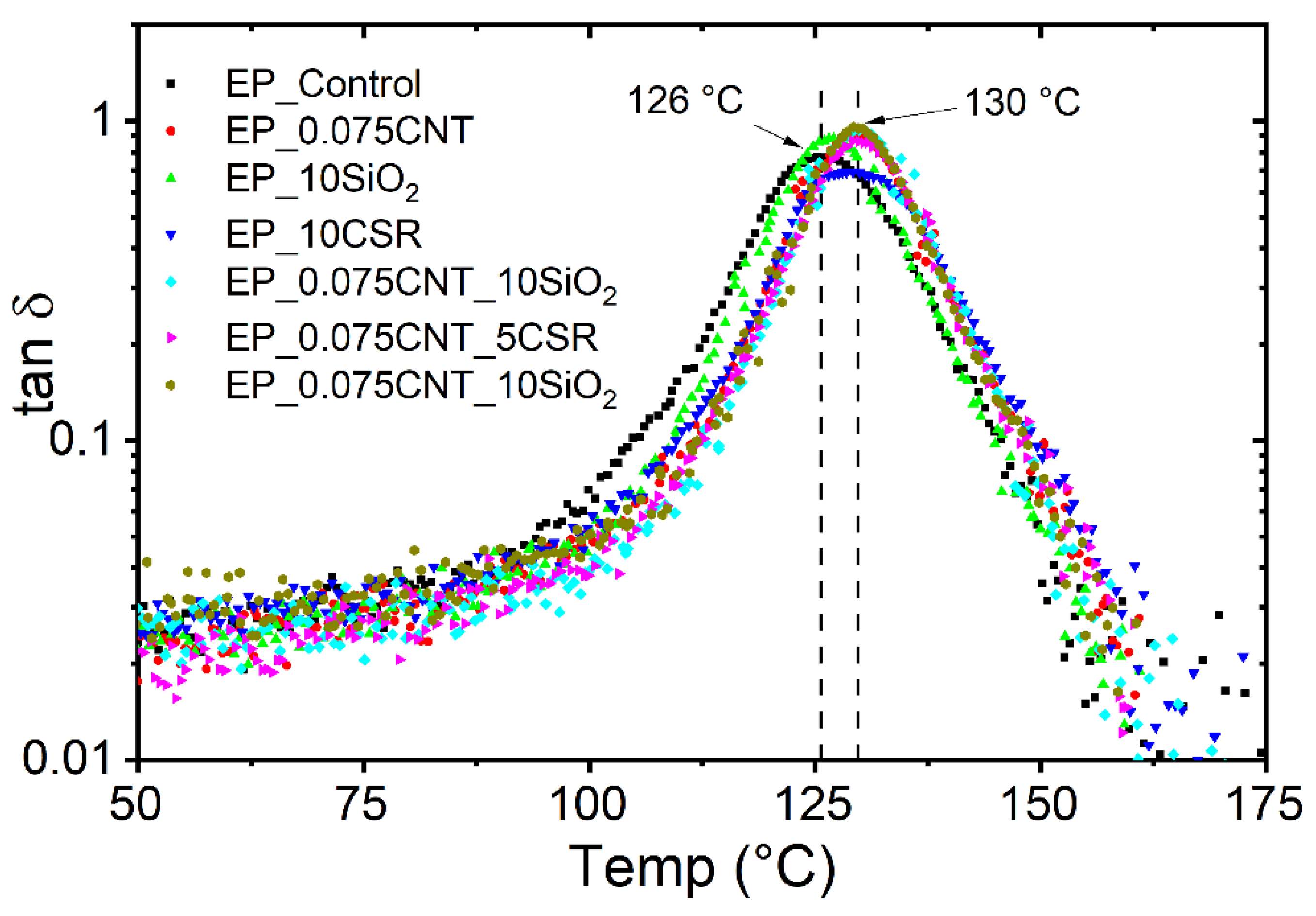
3.2. Dynamic Mechanical Thermal Analysis
3.3. Electrical Conductivity
3.4. Tensile Properties
3.5. Fracture Tests
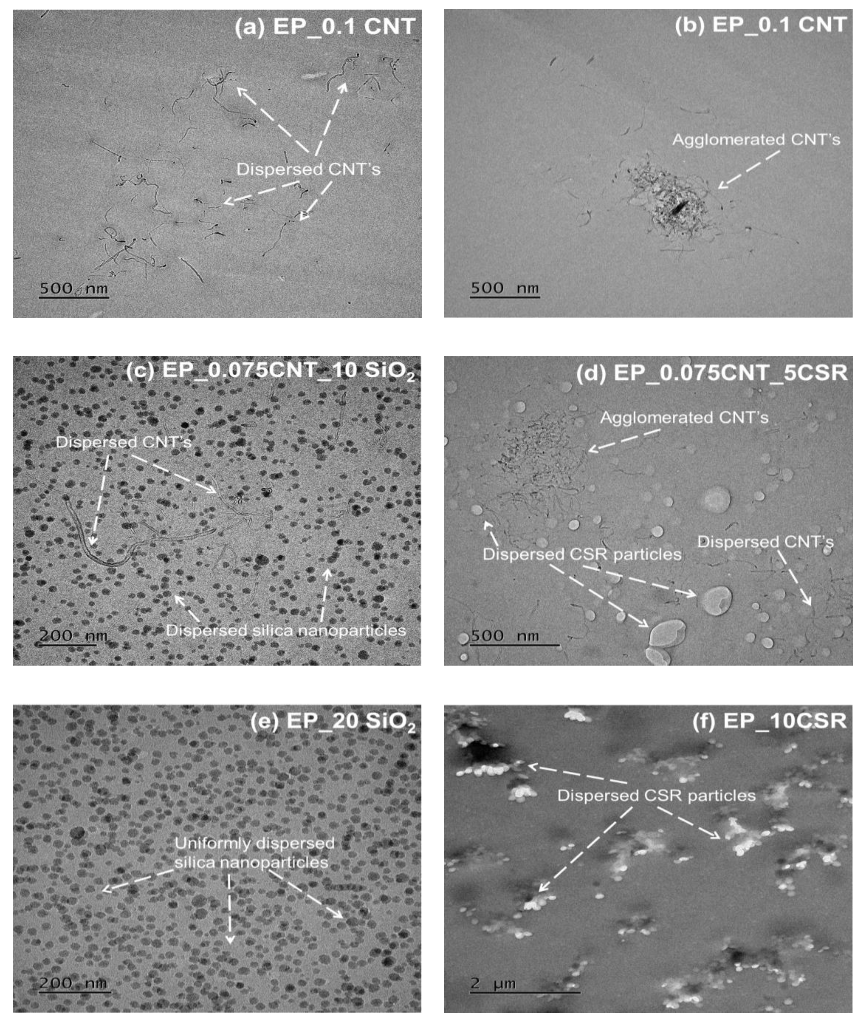
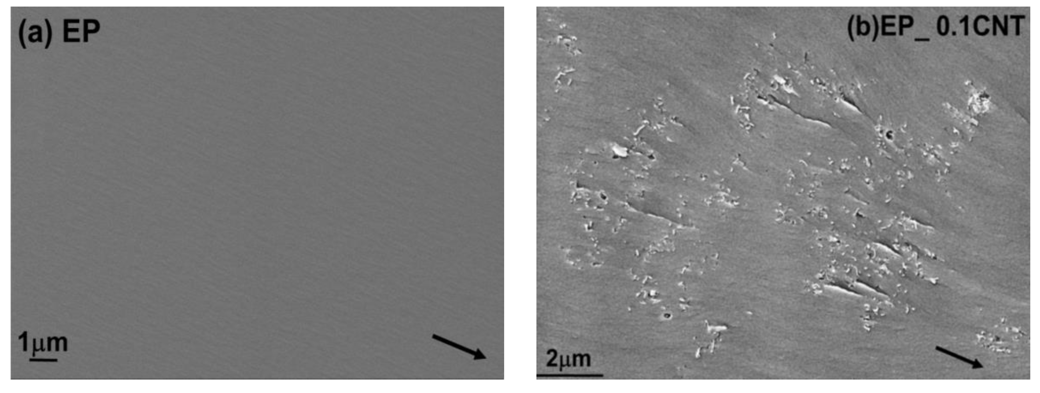
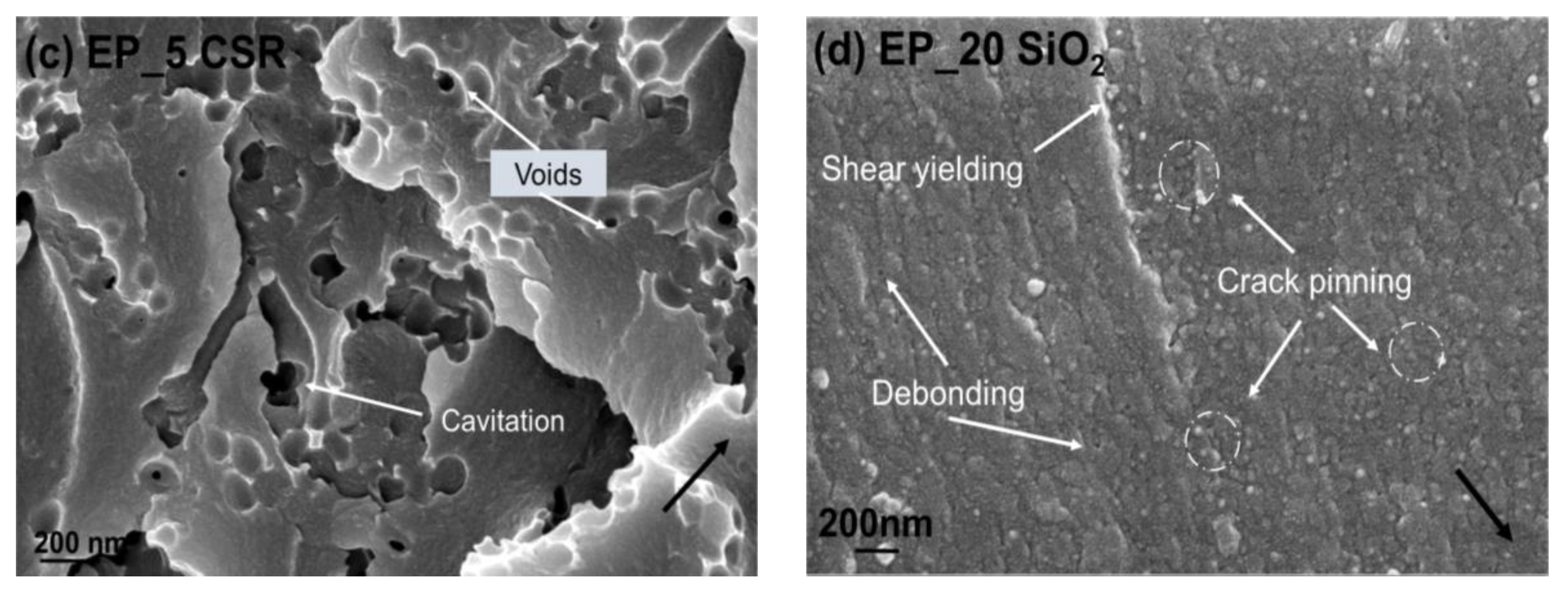
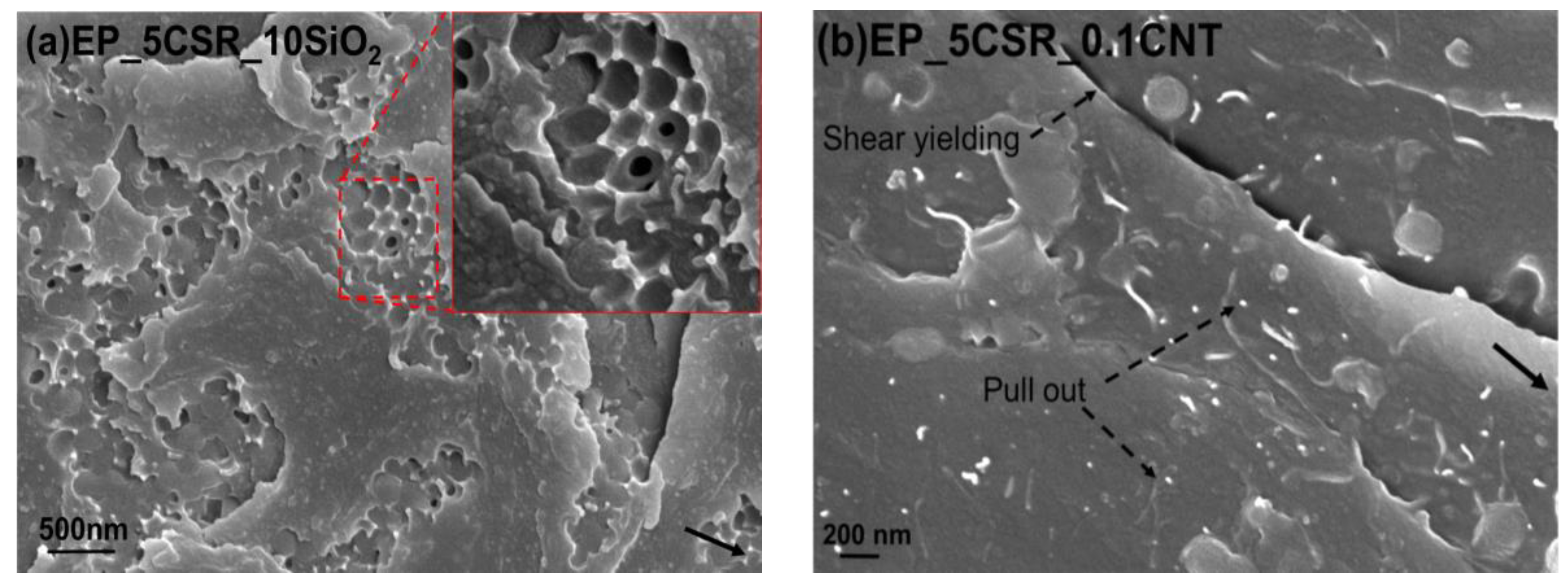
3.6. Microscopy Studies
4. Results
5. Conclusions
Author Contributions
Funding
Acknowledgments
Conflicts of Interest
References
- Breuer, P.U. Commercial Aircraft Composite Technology; Springer: Berlin/Heidelberg, Germany, 2016. [Google Scholar]
- Kunz, S.C.; Syre, J.A.; Assink, R.A. Morphology and toughness characterization of epoxy resins modified with amine and carboxyl terminated rubbers. Polymer 1982, 23, 1897–1906. [Google Scholar] [CrossRef]
- Sultan, J.N.; McGarry, F. Effect of rubber particle size on deformation mechanisms in glassy epoxy. Polym. Eng. Sci. 1973, 13, 29–34. [Google Scholar] [CrossRef]
- Pearson, R.A.; Yee, A.F. Toughening mechanisms in elastomer-modified epoxies. J. Mater. Sci. 1989, 24, 2571–2580. [Google Scholar] [CrossRef] [Green Version]
- Yee, A.F.; Pearson, R.A. Toughening mechanisms in elastomer-modified epoxies Part 1 Mechanical studies. J. Mater. Sci. 1986, 21, 2462–2474. [Google Scholar] [CrossRef]
- Lin, K.F.; Shieh, Y.D. Core-shell particles designed for toughening the epoxy resins. II. Core-shell-particle-toughened epoxy resins. J. Appl. Polym. Sci. 1998, 70, 2313–2322. [Google Scholar] [CrossRef]
- Klingler, A.; Bajpai, A.; Wetzel, B. The effect of block copolymer and core-shell rubber hybrid toughening on morphology and fracture of epoxy-based fibre reinforced composites. Eng. Fract. Mech. 2018, 203, 81–101. [Google Scholar] [CrossRef]
- Bajpai, A.; Alapati, A.K.; Wetzel, B. Toughening and Mechanical Properties of Epoxy Modified with Block Co-polymers and MWCNTs. Procedia Struct. Integr. 2016, 2, 104–111. [Google Scholar] [CrossRef] [Green Version]
- Bajpai, A.; Alapati, A.; Klingler, A.; Wetzel, B. Tensile Properties, Fracture Mechanics Properties and Toughening Mechanisms of Epoxy Systems Modified with Soft Block Copolymers, Rigid TiO2 Nanoparticles and Their Hybrids. J. Compos. Sci. 2018, 2, 72. [Google Scholar] [CrossRef]
- Wetzel, B.; Rosso, P.; Haupert, F.; Friedrich, K. Epoxy nanocomposites—Fracture and toughening mechanisms. Eng. Fract. Mech. 2006, 73, 2375–2398. [Google Scholar] [CrossRef]
- Lee, J.; Yee, A.F. Fracture of glass bead/epoxy composites: On micro-mechanical deformations. Polymer 2000, 41, 8363–8373. [Google Scholar] [CrossRef]
- Hsieh, T.H.; Kinloch, A.J.; Masania, K.; Taylor, A.C.; Sprenger, S. The mechanisms and mechanics of the toughening of epoxy polymers modified with silica nanoparticles. Polymer 2010, 51, 6284–6294. [Google Scholar] [CrossRef] [Green Version]
- Liang, Y.L.; Pearson, R.A. The toughening mechanism in hybrid epoxy-silica-rubber nanocomposites. Polymer 2010, 51, 4880–4890. [Google Scholar] [CrossRef]
- Hsieh, T.H.; Kinloch, A.J.; Masania, K.; Lee, J.S.; Taylor, A.C.; Sprenger, S. The toughness of epoxy polymers and fibre composites modified with rubber microparticles and silica nanoparticles. J. Mater. Sci. 2011, 46, 4092. [Google Scholar] [CrossRef]
- Duke, C.B. Metal-filled polymers—properties and applications, Swapan, K. Bhattacharya, Ed.; Marcel Dekker. J. Polym. Sci. C Polym. Lett. 1987, 25, 263. [Google Scholar] [CrossRef]
- Mamunya, Y.P.; Muzychenko, Y.V.; Pissis, P.; Lebedev, E.V.; Shut, M.I. Percolation phenomena in polymers containing dispersed iron. Polym. Eng. Sci. 2002, 42, 90–100. [Google Scholar] [CrossRef]
- Zhou, Y.X.; Wu, P.X.; Cheng, Z.Y.; Ingram, J.; Jeelani, S. Improvement in electrical, thermal and mechanical properties of epoxy by filling carbon nanotube. Express Polym. Lett. 2008, 2, 40–48. [Google Scholar] [CrossRef]
- Ma, P.C.; Kim, J.K.; Tang, B.Z. Effects of silane functionalization on the properties of carbon nanotube/epoxy nanocomposites. Compos. Sci. Technol. 2007, 67, 2965–2972. [Google Scholar] [CrossRef] [Green Version]
- Fiedler, B.; Gojny, F.H.; Wichmann, M.H.; Nolte, M.C.; Schulte, K. Fundamental aspects of nano-reinforced composites. Compos. Sci. Technol. 2006, 66, 3115–3125. [Google Scholar] [CrossRef]
- Hsieh, T.H.; Kinloch, A.J.; Taylor, A.C.; Kinloch, I.A. The effect of carbon nanotubes on the fracture toughness and fatigue performance of a thermosetting epoxy polymer. J. Mater. Sci. 2011, 46, 7525–7535. [Google Scholar] [CrossRef]
- Gojny, F.H.; Wichmann, M.; Köpke, U.; Fiedler, B.; Schulte, K. Carbon nanotube-reinforced epoxy-composites: Enhanced stiffness and fracture toughness at low nanotube content. Compos. Sci. Technol. 2004, 64, 2363–2371. [Google Scholar] [CrossRef]
- Sika GmbH. Product specifications for Biresin CR144 and Technical Data Sheet; Sika GmbH: Stuttgart, Germany, 2017. [Google Scholar]
- Kaneka Belgium NV Technical Data Sheet—Kane Ace Trade Mark; Brussels, Belgium. 2015.
- Plastics—Determination of Fracture Toughness (GIc and KIc)—Linear Elastic Fracture Mechanics (LEFM) Approach; ISO 13586:2000(E); ISO (The International Organization for Standardization): Geneva, Switzerland, 2000.
- Kinloch, A.J. Stresses in Adhesive Joints. In Adhesion and Adhesives: Science and Technology; Springer: Berlin/Heidelberg, Germany, 1987; p. 209. [Google Scholar]
- Demain, A.; Issi, J.P. The Effect of Fiber Concentration on the Thermal Conductivity of a Polycarbonate/Pitch-Based. J. Compos. Mater. 1993, 27, 668–683. [Google Scholar] [CrossRef]
- Grossiord, N.; Loos, J.; Laake, L.C.; Maugey, M.; Zakri, C.; Koning, C.E.; Hart, A.J. High conductivity polymer nanocomposites obtained by tailoring the characteristics of carbon nanotube fillers. Adv. Funct. Mater. 2008, 20, 3226–3234. [Google Scholar] [CrossRef]
- Ma, P.; Mo, S.; Tang, B.; Kim, J. Dispersion, interfacial interaction and re-agglomeration of functionalized carbon nanotubes in epoxy composites. Carbon 2010, 48, 1824–1834. [Google Scholar] [CrossRef]
- Pearson, R.A.; Yee, A.F. Influence of particle size and particle size distribution on toughening mechanisms in rubber-modified epoxies. J. Mater. Sci. 1991, 26, 3828–3844. [Google Scholar] [CrossRef] [Green Version]
- Bagheri, R.; Pearson, R.A. Role of plastic cavitation in rubber toughened epoxies. Polymer 1996, 37, 5597–5600. [Google Scholar] [CrossRef]
- Kinloch, A.J.; Young, R.J. Fracture Behaviour of Polymers; Elsevier: New York, NY, USA, 1983. [Google Scholar]
- Dittanet, P.; Pearson, R.A. Effect of bimodal particle size distributions on the toughening mechanisms in silica nanoparticle filled epoxy resin. Polymer 2013, 54, 1832–1845. [Google Scholar] [CrossRef]
- Quan, D.; Pearson, R.A.; Ivankovic, A. Interaction of toughening mechanisms in ternary nanocomposites. Polym. Compos. 2018, 39, 3482–3496. [Google Scholar] [CrossRef]


| System | L1100 (gm) | Hardener 943 (gm) | Modifier (gm) |
|---|---|---|---|
| EP_Ref | 142 | 33 | - |
| EP_0.075CNT | 116 | 28 | 5.65 |
| EP_0.1 CNT | 114 | 28 | 7.5 |
| EP_10SiO2 | 87 | 26 | 38 |
| EP_20SiO2 | 51.5 | 24 | 76.13 |
| EP_5CSR | 103 | 27 | 20.68 |
| EP_10CSR | 83.5 | 26 | 41.35 |
| EP_0.075CNT_10 SiO2 | 81.78 | 26 | 5.51/37.73 |
| EP_0.075 CNT_5 CSR | 96.74 | 27 | 5.51/20.68 |
| EP_5CSR_10SiO2 | 66.66 | 25 | 20.6/37.73 |
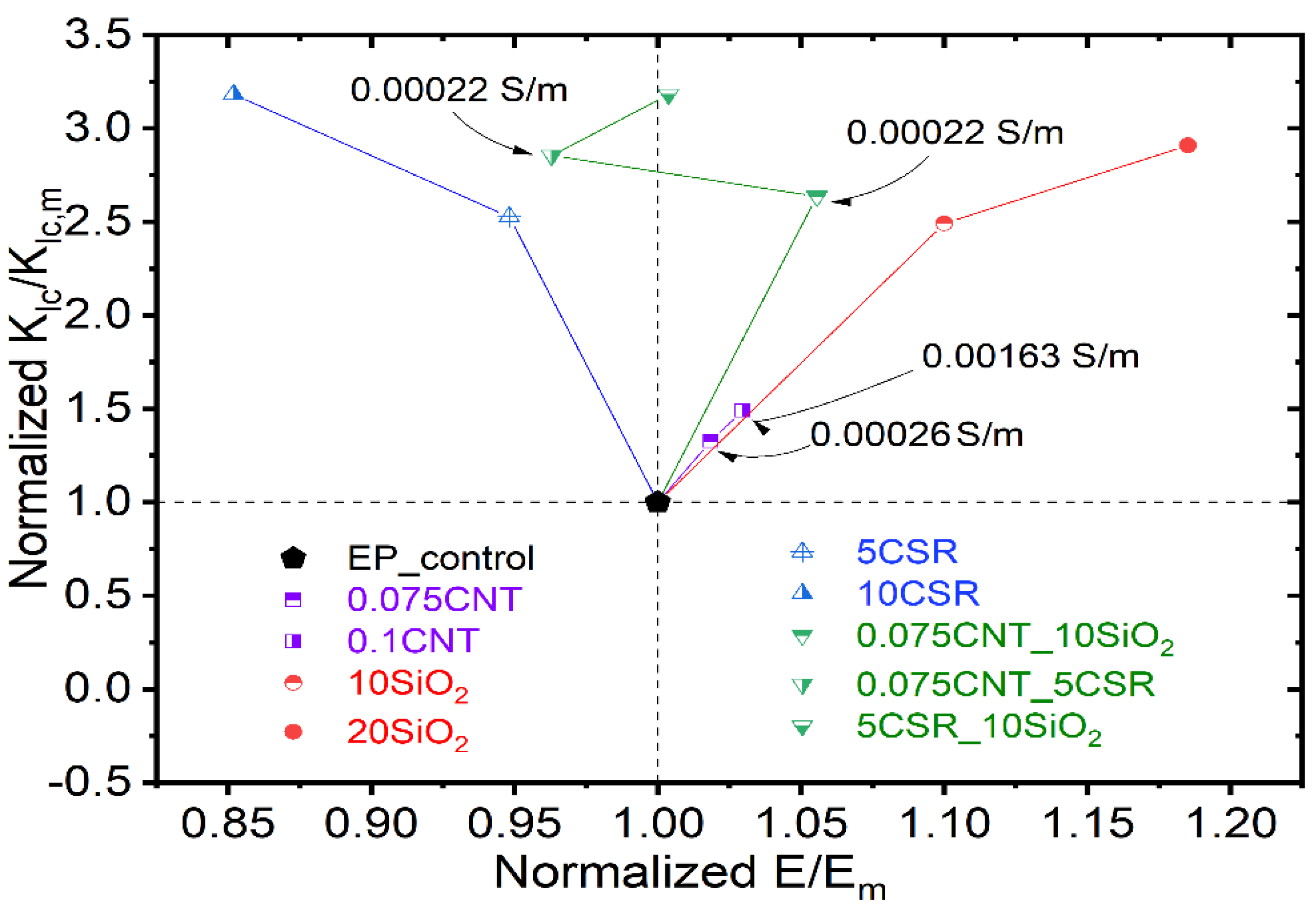
| Samples | Conductivity (S/m) |
|---|---|
| EP_Ref. | - |
| EP_0.05CNT | - |
| EP_0.075CNT | 0.00026 |
| EP_0.1CNT | 0.00163 |
| EP_0.075 CNT_10 SiO2 | 0.00022 |
| EP_0.075 CNT_5 CSR | 0.00021 |
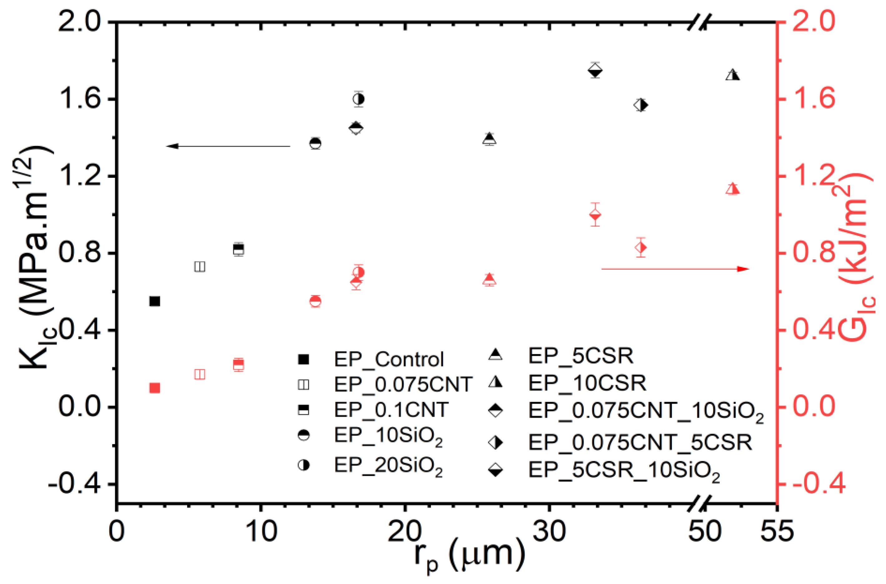
| Systems | Et [MPa] | σm [MPa] | εm [%] | KIc [MPa·m1/2] | GIc [kJ/m2] |
|---|---|---|---|---|---|
| EP | 2700 (±15) | 78 (±0.5) | 6.8 (±0.1) | 0.55 (±0.08) | 0.10 (±0.07) |
| EP_0.075CNT | 2750 (±35) | 70 (±0.6) | 6.2 (±0.2) | 0.73 (±0.12) | 0.17 (±0.06) |
| EP_0.1CNT | 2730 (±45) | 65 (±0.7) | 5.9 (±0.1) | 0.82 (±0.07) | 0.22 (±0.05) |
| EP_10SiO2 | 2970 (±17) | 85 (±0.9) | 6.3 (±0.2) | 1.37 (±0.08) | 0.55 (±0.06) |
| EP_20SiO2 | 3200 (±10) | 90 (±0.4) | 6.1 (±0.3) | 1.60 (±0.10) | 0.70 (±0.07) |
| EP_5CSR | 2560 (±12) | 63 (±0.6) | 5.2 (±0.4) | 1.39 (±0.05) | 0.66 (±0.03) |
| EP_10CSR | 2300 (±24) | 55 (±0.6) | 4.7 (±0.2) | 1.72 (±0.07) | 1.13 (±0.04) |
| EP_0.075CNT_10SiO2 | 2850 (±25) | 82 (±0.6) | 6.1 (±0.3) | 1.45 (±0.06) | 0.65 (±0.04) |
| EP_0.075CNT_5CSR | 2600 (±27) | 60 (±0.6) | 4.5 (±0.2) | 1.57 (±0.04) | 0.83 (±0.05) |
| EP_5CSR_10SiO2 | 2710 (±17) | 70 (±0.8) | 4.8 (±0.3) | 1.75 (±0.08) | 1.00 (±0.06) |
© 2019 by the authors. Licensee MDPI, Basel, Switzerland. This article is an open access article distributed under the terms and conditions of the Creative Commons Attribution (CC BY) license (http://creativecommons.org/licenses/by/4.0/).
Share and Cite
Bajpai, A.; Carlotti, S. The Effect of Hybridized Carbon Nanotubes, Silica Nanoparticles, and Core-Shell Rubber on Tensile, Fracture Mechanics and Electrical Properties of Epoxy Nanocomposites. Nanomaterials 2019, 9, 1057. https://doi.org/10.3390/nano9071057
Bajpai A, Carlotti S. The Effect of Hybridized Carbon Nanotubes, Silica Nanoparticles, and Core-Shell Rubber on Tensile, Fracture Mechanics and Electrical Properties of Epoxy Nanocomposites. Nanomaterials. 2019; 9(7):1057. https://doi.org/10.3390/nano9071057
Chicago/Turabian StyleBajpai, Ankur, and Stéphane Carlotti. 2019. "The Effect of Hybridized Carbon Nanotubes, Silica Nanoparticles, and Core-Shell Rubber on Tensile, Fracture Mechanics and Electrical Properties of Epoxy Nanocomposites" Nanomaterials 9, no. 7: 1057. https://doi.org/10.3390/nano9071057