Article

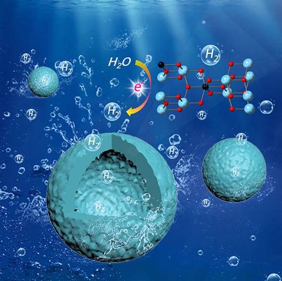
Surface Modification of Hollow Structure TiO2 Nanospheres for Enhanced Photocatalytic Hydrogen Evolution

1
School of New Energy, Nanjing University of Science and Technology, Fuxing Road 8, Jiangyin 214000, China
2
College of Science & School of Plant Protection, Anhui Agricultural University, Hefei 230036, China
3
State Key Laboratory of Catalysis, Dalian Institute of Chemical Physics, Chinese Academy of Sciences, 457 Zhongshan Road, Dalian 116023, China
4
Dalian National Laboratory for Clean Energy, 457 Zhongshan Road, Dalian 116023, China
5
College of Chemistry and Chemical Engineering, Inner Mongolia University (Inner Mongolia), Hohhot 010021, China
6
DICP-Surrey Joint Centre for Future Materials, Department of Chemical and Process Engineering, and Advanced Technology Institute, University of Surrey, Guildford GU2 7XH, Surrey, UK
*
Authors to whom correspondence should be addressed.
These authors contributed equally to this work.
Nanomaterials 2023, 13(5), 926; https://doi.org/10.3390/nano13050926
Submission received: 12 January 2023 / Revised: 27 February 2023 / Accepted: 1 March 2023 / Published: 3 March 2023
(This article belongs to the Special Issue Synthesis of TiO2 Nanoparticles and Their Catalytic Activity)

Abstract

:
Engineering the surface structure of semiconductor is one of the most promising strategies for improving the separation and transfer efficiency of charge, which is a key issue in photocatalysis. Here, we designed and fabricated the C decorated hollow TiO2 photocatalysts (C–TiO2), in which 3-aminophenol-formaldehyde resin (APF) spheres were used as template and carbon precursor. It was determined that the C content can be easily controlled by calcinating the APF spheres with different time. Moreover, the synergetic effort between the optimal C content and the formed Ti–O–C bonds in C–TiO2 were determined to increase the light absorption and greatly promote the separation and transfer of charge in the photocatalytic reaction, which is verified from UV–vis, PL, photocurrent, and EIS characterizations. Remarkably, the activity of the C–TiO2 is 5.5-fold higher than that of TiO2 in H2 evolution. A feasible strategy for rational design and construction of surface-engineered hollow photocatalysts to improve the photocatalytic performance was provided in this study.

Graphical Abstract

1. Introduction

With the development of human society and rampant industrial growth, the need for renewable hydrogen energy has become increasingly urgent due to the non-renewability of fossil fuels. Sunlight as an inexhaustible source of energy can be converted into electricity and chemical energy by catalysis technologies [1,2,3]. Photocatalytic H2 evolution from water splitting has attracted particular interest for the sustainable survival and development of mankind [4,5,6], whereupon semiconductors as photocatalysts are one of the most important and indispensable elements in photocatalytic reaction system [7]. In a wide variety of semiconductor catalysts, Titanium oxide (TiO2) as a promising photocatalyst has been widely studied for photocatalytic H2 production due to low toxicity and high stability [8,9,10]. Nevertheless, its photocatalytic application is still restricted owing to the rapid recombination of photogenerated charge carriers [11,12,13]. Consequently, it is highly desired to develop TiO2-based photocatalysts with superior photogenerated charge separation.
A lot of strategies have been developed to enhance the photocatalytic performance, including the structural design and modification [11,12,13]. The fabrication of the hollow structure [14,15,16,17] has been extensively proved to increase the light absorption due to multiple reflection and refraction of light in the super-large cavity [18,19,20], and shorten the transfer distance of photogenerated charges [21]. In addition, element doping provides a unique opportunity to improve the photocatalytic performance by tuning the energy band and photogenerated charge separation efficiency [22,23]. For instance, Yang et al. reported that P doping efficiently improves photocatalytic H2 evolution of TiO2 photocatalyst by enhancing light harvesting and charge separation [24]. Reddy et al. prepared the N-doped TiO2 photocatalysts, and new levels of N atoms were generated near the valence band maximum of TiO2 to enhance the optical properties and increase the charge separation [25]. Incorporating dopants into the TiO2 not only effectively overcomes the drawback of low solar energy utilization capacity of pure TiO2, but also promotes the transfer of holes and photogenerated electrons. By affecting the electronic environment of O anion and Ti ion, the utilization of light under C doping was promoted and the sensitization of TiO2 was also increased. For instance, Zheng et al. reported that photocatalytic reactions were performed using light, and the performance of TiO2 toward H2 production was greatly improved by C doping [26].
Here, we fabricated the C modified hollow TiO2 photocatalysts (hollow C–TiO2) by hard-template method, in which the 3-aminophenol-formaldehyde resin (APF) nanospheres were selected as growth templates as well as carbon source for the hollow C–TiO2 photocatalysts. The hollow structure and the carbon content of the hollow C–TiO2 can be tunned by finely modulating the calcination conditions. Interestingly, the formation of Ti-O-C bonds on C–TiO2 photocatalysts via FTIR and XPS characterization resulted in a remarkable improvement for photocatalytic H2 evolution compared with bare TiO2. This enhancement is mainly due to improving separation and transfer of the charge, and it is verified by PL, SPV, and EIS characterizations. A common and effective method to construct the hollow photocatalysts with C doping for efficient photocatalytic H2 evolution is provided in this work.

2. Experimental

2.1. Materials

All reagents were used as received without further purification. 3-Aminophenol (3-AP, 99.0%) (Adamas Reagent Co., LTD, Shanghai, China). Tetrabutyl orthotitanate (TBOT, 98.0%) (Aladdin Co., LTD, Fengxian District, Shanghai, China). Ammonia aqueous solution (25.0–28.0%), absolute ethanol (EtOH, 99.7%), formaldehyde aqueous solution (37.0–40.0%), and acetonitrile (99.8%) were obtained from (Sinopharm Chemical Reagent Co. Ltd., Shanghai, China). Deionized (DI) water was used in the experiments.
Synthesis of the 3-aminophenol-formaldehyde resin spheres (APF spheres) and the carbon spheres (C spheres) was conducted. APF spheres were synthesized according to a previously reported procedure [27]. Typically, we mixed ammonia aqueous solution (0.2 mL) with a solution containing EtOH (16 mL) and deionized water (40 mL), then the mixed solution was stirred for 3 min. Subsequently, 3-AP (0.8 g) was added in the mixed solution and continually stirred for more than 30 min. Then, we added the formaldehyde aqueous solution (1.12 mL) to the above reaction solution and stirred for 24 h at 30 °C, and under a static condition the solution was subsequently heated at 100 °C for 24 h in a Teflon-lined autoclave. We recovered the solid product by centrifugation which was washed with ethanol three times. The resulting APF was heated for 2 h under N2 atmosphere at 700 °C to obtain pure carbon (C) sample.
Coating APF with TiO2 (APF@TiO2) was performed. The as-prepared APF (0.5 g) was dispersed in EtOH (100 mL) in an ice bath and vigorous stirring. Acetonitrile (35 mL) and ammonia aqueous solution (0.75 mL), TBOT (2 mL) in a mixed solvent of EtOH (15 mL) and acetonitrile (5 mL) were injected into the mixture. After 5 h, the composite was washed with ethanol and separated by centrifugation to obtain APF@TiO2 core–shell composites.
Synthesis of the C modified TiO2 photocatalysts (C–TiO2) was performed. The resulting APF@TiO2 core–shell composites were heated under air atmosphere at 450 °C with a heating rate of 5 °C/min, and maintained at 450 °C for 1 h, 2 h or 5 h to obtain APF-TiO2-x samples (x = 1, 2, 3, respectively). Then, the APF-TiO2-x composites were heated with a heating rate of 2 °C/min at 700 °C in N2 atmosphere for 2 h and cooled to room temperature, and the resulting samples were labelled, respectively, as C–TiO2–1, C–TiO2–2 and C–TiO2–3.
Synthesis of pure TiO2 was performed. Pure TiO2 was prepared under the above experimental conditions except for adding APF.

2.2. Characterization

The morphology features of the products were characterized using transmission electron microscope (TEM, HT7700, HHT Inc., Tokyo, Japan), scanning electron microscopy (SEM, FEI QUANTA 200 F, FEI inc., Hillsboro, NK, USA) and high-resolution transmission electron microscopy (HRTEM, JEM-F200, JEOL Inc., Tokyo, Japan)). The structural characteristics of catalyst were carried out by X-ray diffraction (XRD, D/Max2500PC (Rigaku Inc., Tokyo, Japan) analysis which used a Rigaku D/Max2500PC diffractometer. We used a home-assembled Raman spectrograph (DL-3 UV Raman spectroscopy with operando system) and excited the Raman spectra at 532 nm with spectral resolution of 2 cm−1. In the range of 4000–400 cm−1, a Nicolet Nexus 470 spectrometer using KBr pellet was used to record the Fourier-transform infrared (FTIR) spectra (Nicolet Inc., Mountain, WI, USA). We collected N2 adsorption–desorption isotherms on Micromeritics Tristar II 3020 automated analyzer at 77 K, and the surface areas were determined according to the Brunauer–Emmett–Teller (BET) method: Tristar II 3020 (Micromeritics Inc. Atlanta, GA, USA). X-ray photoelectron spectroscopy (XPS) was characterized on a Thermo ScientificTM K-AlphaTM+ spectrometer (Thermo Scientific Inc., Waltham, MA, USA). We collected UV–vis diffuse reflectance spectra (DRS) on a UV-2700 spectrophotometer (SGLC Inc., Shanghai, China). Photoluminescence spectra (PL) (λex = 325 nm, λem = 340–600 nm) were measured using a JASCO fluorescence spectrometer (FP-8500) (JASCO China Inc., Shanghai, China) with a Xe lamp as the excitation light source at room temperature. Surface photovoltage (SPV) spectra were measured with a home-assembled surface photovoltage with a SR830 DSP lock-in amplifier of Stanford Research Systems at room temperature. TGA (Mettler-Toledo Inc., Zurich, Switzerland) analyses were performed on a TGA/DSC-1 thermogravimetric analyzer provided by the Mettler-Toledo Instrument.

2.3. Photoelectrochemical Measurements

The C–TiO2 samples (0.05 g) were dispersed in 2 mL of ethanol and 10 μL of 5% nafion reagent. Then, the above mixed solution was sonicated for 30 min. Finally, the given 50 μL solution was dropped on the conductive glass (FTO) and dried in order to use it as working electrodes. A platinum electrode was used as the counter electrode, and a saturated Ag/AgCl electrode was selected as the reference electrode. Electrochemical impedance spectroscopy (EIS) and the photocurrent-time curves of the samples were evaluated in 1 M Na2SO4 electrolyte in a three-electrode quartz cell, and performed by an electrochemical workstation (CH Instruments Inc, Shanghai, China). A 300w Xe lamp was used as the light source. Mott–Schottky (M-S) plots were measured in 0.1 M Na2SO4 electrolyte from 1 V to −1 V at 1000 Hz.

2.4. Photocatalytic Activity

Photocatalytic H2 evolution was carried out using a 300 W Xe lamp (prefect light) in a closed gas circulation and inhalation system. The 20.0 mg of the C–TiO2 photocatalyst was dispersed in solution containing H2O (80 mL) and CH3OH (20 mL), which was conducted by venting away the internal air to achieve complete degassing. We decided to evolve the amount of H2 by an online gas chromatograph (GC-7900, Shanghai Techcomp. TCD, Ar carrier, Shanghai, China).

3. Results and Discussion

The schematic representation of the synthesis of the hollow C–TiO2 photocatalysts is presented in Figure 1a. The synthesis steps involved the preparation of 3-aminophenol-formaldehyde resin (APF) spheres templates (Figure S1), TiO2 coating on APF surface (APF@TiO2), and transformation of APF@TiO2 into hollow C–TiO2 photocatalysts through controlling the calcination conditions. Specifically, the TiOx shells through the hydrolysis, oligomerization, and condensation of tetrabutyl orthotitanate (TBOT) coated on APF spheres surface to fabricate APF@TiO2 (Figure S2). The C–TiO2 hollow sphere was synthesized by heating APF@TiO2 in air atmosphere at 450 °C at different times to modulate the C content (APF-TiO2), followed by heating at 700 °C under N2 atmosphere to carbonize APF. The resulting hollow C–TiO2 samples were labelled as C–TiO2–1, C–TiO2–2 and C–TiO2–3, respectively. SEM images of a representative sample, C–TiO2–2, show uniform microsphere morphologies with a diameter of approximately 750 nm (Figure S3), among which a broken sphere (Figure 1b) clearly indicates the hollow sphere structure. As shown in Figure 1c, the hollow microsphere is uniform and regular. The average particle sizes calculated by TEM images were 750 nm, which is in agreement with SEM results. HRTEM further investigated the crystal structure of the synthesized C–TiO2–2 (Figure 1d). It can be seen that the lattice spacing of C–TiO2–2 is 0.35 nm, which can be well directed to the (101) flat of anatase type TiO2 [28]. The EDS elemental mapping of the energy spectrum in Figure 1f–i, confirms that Ti, O, and C are distributed very uniformly in the hollow spheres of C–TiO2–2, indicating the successful incorporation of C.
To clarify the formation process of hollow C–TiO2 photocatalysts, several samples obtained by controlling the calcination condition are described in detail. Figure 2a–c displays the morphological evolution of APF@TiO2 calcined at 450 °C under air atmosphere at different durations. Yolk–shell APF@TiO2 sphere and hollow APF@TiO2 sphere could be fabricated at a calcination of 1 h and 5 h, respectively. All the C–TiO2 samples by carbonization APF@TiO2 samples at 700 °C for 2 h under N2 atmosphere show the monodisperse nanospheres (Figure 2g–i) with hollow structure (Figure 2d–f).Notably, the C contents estimated by TGA method were approximately 9.1 wt.%, 0.65 wt.%, and 0.085 wt.% for C–TiO2–1, C–TiO2–2, and C–TiO2–3, respectively, indicating that the C contents in the C–TiO2 photocatalyst can be easily tuned by altering the calcination conditions (Table S1). As shown in Figure S4, all the C–TiO2–1, C–TiO2–2 and C–TiO2–3 samples exhibit type IV N2 adsorption–desorption isotherms with a H1 hysteresis loop, which corresponds to the microporous structure. Table S2 shows that the specific surface area of C–TiO2–1, C–TiO2–2 and C–TiO2–3 is 98, 19 and 14 m2/g, respectively, proving that the C content has significant effect on the specific surface area of the hollow C–TiO2.
Furthermore, the structure and composition of C–TiO2 samples were studied by XRD, FTIR and Raman spectroscopy. As shown in Figure 3a, the main diffraction peaks (25.3°, 37.8°, 48.1°, 53.9°, 55.1° and 62.7°) of all the hollow C–TiO2 samples can be indicated as anatase phase. They correspond to (101), (004), (200), (105), (211) and (204) crystal flats. (JCPDS, No. 21–1272). Nevertheless, the peaks increased in intensity with rising of the annealing time under air atmosphere, which is primarily due to the reduced shielding impact of carbonaceous species in the TiO2 hollow structures as well as the grain growth of TiO2 [29]. FTIR spectroscopy also confirmed successful introduction of C into TiO2, with characteristic bands of C appearing at ∼1393 cm−1 corresponding to O–C=O vibrations (Figure 3b). Furthermore, compared with pure TiO2, an extra FTIR band at 1090 cm−1 in connection with Ti–O–C stretching is observed for all the hollow C–TiO2 samples, indicating that Ti–O–C covalent bonds are formed in the C–TiO2 (Figure S5) [30].
The Raman spectra of hollow C–TiO2 photocatalysts with the excitation line at 532 nm are shown in Figure 3c,d. For all the C–TiO2 samples, Raman bands at 144, 198, 394, 515, and 638 cm−1 are observed, which is ascribed to the Eg, Eg, B1g, A1g + B1g, and Eg modes of anatase phase TiO2. Obviously, the stronger Raman bands in intensity are observed for the C–TiO2–3 sample compared with C–TiO2–1 and C–TiO2–2, suggesting that C–TiO2–3 sample displays higher crystallinity. The results are consistent with the XRD. Furthermore, the characteristic Raman bands of the D and G vibration modes of C at 1353 cm−1 and 1588 cm−1 are obviously observed in the C–TiO2–1, indicating that the C element is incorporated into hollow TiO2 photocatalyst. However, the D and G bands decreased in intensity in the C–TiO2–2 sample, while these two Raman bands disappeared nearly in the C–TiO2–3 sample, suggesting that the C content gradually decreased when the calcination time for APF@TiO2 under air atmosphere was increased from 1 h to 5 h, which is consistent with that from Table S1.
More detailed information regarding chemical properties of pure carbon spheres (denoted as C) formed by calcination of APF and the hollow C–TiO2 photocatalyst were obtained by XPS. On the basis of the XPS spectroscopic analysis, it was determined that Ti, O and C existed in the hollow C–TiO2–2 photocatalyst (Figure 4a). In the high resolution C1s XPS of hollow C–TiO2–2 photocatalyst (Figure 4b), the fitted peaks centred at 284.8, 286.1, and 287.0 eV, which were ascribed to the sp2 hybridized C (C–C bonds), the oxygen-bound substance C–O and C=O bonds [31,32,33]. Compared with pure C spheres, the emerging peak in C–TiO2–2 at 288.3 eV is ascribed to the formation of the Ti–O–C covalent band [34]. In Figure 4c, the high-resolution Ti 2p spectra, the two peaks centring at 458.5 eV and 464.2 eV were due to Ti 2p3/2 and Ti 2p1/2. It is reported that C enters the lattice and generates a Ti–O–C covalent bonds and hybrid orbital is formed above the valence band, which enhances visible light adsorption capacity of TiO2 [35]. Compared with pure TiO2, the characteristic peak of C–TiO2–2 at 458.4 eV occurs blue-shifted, which could be related to the change in the environment around Ti4+ species in carbon-doped sample. As shown in Figure 4d, the O1s peak can be decomposed into two peaks, in which the peak at 529.7 eV can be ascribed to lattice oxygen in oxides, and the peak at 531.2 eV was ascribed to hydroxyl (-OH) group [36]. At the same time, we also conducted XPS for C–TiO2–1 and C–TiO2–3 samples (Figure S11).
DRS and M-S measurements were used to study the optical absorption characteristics and electronic bands of the hollow C–TiO2 samples. As displayed in Figure 5a, all the hollow C–TiO2 samples show similar light absorbance in the range of 200–390 nm. In the visible region (400–800 nm), the C–TiO2–1 sample shows the strong absorption due to its high C content, while C–TiO2–3 does not absorb the visible light, which could be ascribed to its very low C content. We can calculate the band gap by (ahυ)1/2 curves of the photon energy (hυ) and the band gap energy (Eg) of C–TiO2–1, C–TiO2–2 and C–TiO2–3 is calculated to be 2.9, 3.0 and 3.2 eV (Figure 5b). The flat-band energy potential (EFB) of the C–TiO2 samples was investigated by M-S measurements. We calculated EFB values using the intercept of axes with potential values at −0.74, −0.56 and −0.28 V vs. NHE for C–TiO2–1, C–TiO2–2 and C–TiO2–3, respectively (Figure 5c). EFB is regarded as approximately 0.1 V below the conduction band (ECB) in many n-type semiconductors [37]. The ECB for C–TiO2–1, C–TiO2–2 and C–TiO2–3 were figured up to be −0.84, −0.66 and −0.38 V, vs. NHE (Figure 5d). Obviously, the hollow TiO2 with Ti-O-C bond resulted in the change in the electronic energy band, and the energy band structure of C–TiO2 can be easily adjusted by carbon doping amount.
To emphasize the important role of surface modification on TiO2 photocatalytic activity, the photocatalytic hydrogen production of C–TiO2 photocatalysts was evaluated in water/methanol solution under Xe lamp irradiation. The pure TiO2 showed low photocatalytic activity, while the C incorporation in TiO2 greatly increased the photocatalytic H2 evolution (Figure 6a and Figure S12). Moreover, the photocatalytic activity of hollow C–TiO2 is relevant to the C content, where C–TiO2–2 showed the highest activity and reached 5.5 times higher than that of pure TiO2. Furthermore, the specific H2 evolution rates (the overall H2 evolution rate was divided by the surface area) of C–TiO2 and TiO2 were also compared (Figure S6). Obviously, the specific H2 evolution rates for C–TiO2 exhibited similar trend to the overall H2 production rate. These results indicate that surface area is not the main factor to enhance of C–TiO2–2 photocatalytic activity. Though the C–TiO2–2 exhibits the weaker light absorption intensity in the visible region compared to C–TiO2–1, the remarkable enhancement for the photocatalytic H2 evolution rate highlights the importance of the optimal C content in the hollow C–TiO2 in photocatalysis. In the stability test, there was no serious inactivation for the C–TiO2–2 in the measurement process of 15 h (Figure 6b). Moreover, the C–TiO2–2 after the photocatalytic experiments were further characterized by SEM, XRD, Raman and XPS (Figures S7–S10). The hollow structure and crystal phase of the C–TiO2–2 were well preserved, suggesting that the C–TiO2 photocatalysts for photocatalytic activity exhibit good long-term durability.
To investigate the main reason for the strong photocatalytic performance on the C–TiO2–2, a series of characterizations were used. PL spectra were recorded to characterize the recombination efficiency of photogenerated electrons and holes from the C–TiO2 (Figure 7a). C–TiO2–1 exhibits a strong PL intensity, which is caused by the reorganization of the native carriers. C–TiO2–3 has a stronger trapping ability and a stronger carrier separation ability compared with pure C–TiO2–1. The PL intensity of C–TiO2–2 is significantly quenched compared with C–TiO2–1 and C–TiO2–3, implying that optimized C content is beneficial for charge separation. Moreover, under light irradiation, SPV spectroscopy was used to reveal the change in surface potential barrier of C–TiO2 samples (Figure 7b). Notably, the SPV signal of C–TiO2–2 is much stronger than that of the C–TiO2–1 and C–TiO2–3, which means that the separation of electrons and holes is greatly promoted in C–TiO2–2. As displayed in Figure 7c, the instantaneous photocurrent response results show that C–TiO2–2 have the highest photocurrent density compared to C–TiO2–1 and C–TiO2–3, indicating better charge separation and transfer ability of C–TiO2–2. The charge transfer resistance tested from the EIS with the fitted circuit diagram is displayed in Figure 7d. The results show that the smaller the radius, the smaller the interface charge transfer resistance. Obviously, in the EIS Nyquist plots, the arc radius of the C–TiO2–2 photocatalyst is smaller than that of the C–TiO2–1 and C–TiO2–3, explaining that the interfacial transfer charge resistance between the electrolyte and electrode of the C–TiO2–2 photocatalyst is much smaller [38]. These results demonstrate that the superior photocatalytic activity on C–TiO2–2 can be attributed to C modification as well as hollow TiO2 structure, promoting the charge separation and transfer ability. As shown in Figure 8, the mechanism of H2 generation by C–TiO2 photocatalysis is as follows: Photogenerated electron–hole pairs are generated from C–TiO2 under photoexcitation conditions. Then, CH3OH is used as sacrificial reagent to react with h+, and the e- reduces H+ to produce H2. Our work reports high activity compared to other related types of work at the same time (Table S3).

4. Conclusions

In summary, we constructed C-modified hollow TiO2 photocatalysts by calcinating APF spheres as template and carbon source. The formed Ti–O–C bonds on the surface of TiO2 shell are confirmed by FTIR and XPS spectra, which is of benefit to promote the fact that the photoexcited charge carriers separate and transfer. C-modified TiO2 exhibited improved performance for photocatalytic H2 evolution. Remarkably, the H2 evolution activity of C–TiO2–2 is 5.5-fold higher than that of bare TiO2. We believe that our study provides a typical case for the efficient conversion of solar energy by hollow photocatalysts.

Supplementary Materials

The following supporting information can be downloaded at: https://www.mdpi.com/article/10.3390/nano13050926/s1. Figure S1. SEM images of APF at different magnifications (a) 2 μm (b) 200 nm. Figure S2. SEM images of APF@TiO2 at different magnifications (a) 2 μm (b) 1 μm. Figure S3. TEM images of the (a) APF–TiO2–2 and (b) C–TiO2–2. Figure S4. Nitrogen adsorption-desorption isotherms of the prepared C–TiO2–1, C–TiO2–2 and C–TiO2–3 nanoreactors. Figure S5. FTIR spectrum of pure C sphere. Figure S6. Photocatalytic hydrogen evolution of pure TiO2, C–TiO2–1, C–TiO2–2 and C–TiO2–3 with normalized by their specific surface area separately under simulated solar light irradiation. Figure S7. SEM images of the C–TiO2–2 before (a) and after (b) three cycles of photocatalytic hydrogen evolution. Figure S8. XRD patterns of the C–TiO2–2 before and after three cycles of photocatalytic hydrogen evolution. Figure S9. (a) Raman spectra of C–TiO2–2 sample before and after three cycles of photocatalytic hydrogen evolution. (b) Partial enlargement of the selective area in (a). Figure S10. (a) XPS spectra of the C–TiO2–2 before and after three cycles of photocatalytic hydrogen evolution.(b–d) C 1s, Ti 2p, O 1s XPS spectra of the C–TiO2–2 before and after three cycles of photocatalytic hydrogen evolution. Figure S11. (a) XPS survey spectra of the prepared C–TiO2–1 and C–TiO2–3. (b) C 1s XPS spectra of the C–TiO2–1 and C–TiO2–3. (c) Ti 2p XPS spectra of the C–TiO2–1 and C–TiO2–3. (d) O 1s XPS spectra of the C–TiO2–1 and C–TiO2–3. Figure S12. Photocatalytic hydrogen evolution of sample C–TiO2–2 under simulated sunlight irradiation. Table S1. The estimated carbon content in C–TiO2–1, C–TiO2–2 and C–TiO2–3 by TGA method. Table S2. Summary parameters of related sample from the N2 adsorption dates. Table S3. Comparison of similar jobs [26,39,40,41,42,43,44].

Author Contributions

J.L. and J.Z. conceived and designed the experiment. G.N. and C.Z. performed the experimental measurements. Y.Z., F.C., W.G. and C.Z. carried out the data analysis. Y.Z. and C.S. wrote the paper. M.L., S.Y., J.L. and J.Z. carefully edited and amended the manuscript. All authors have read and agreed to the published version of the manuscript.

Funding

This research was funded by (the National Natural Science Foundation of China) Grant Number (21902157), (the National Natural Science Foundation of China) Grant Number (22172068), (Starting Fund for Scientific Research of High-Level Talents, Anhui Agricultural University) Grant Number (rc382108), (Key Research and Development Plan of Anhui Province) Grant Number (2022e07020037), and (Natural Science Foundation of Jiangsu Province) Grant Number (BK20221485).

Data Availability Statement

The original contributions presented in the study are included in the article/supplementary material, further inquiries can be directed to the corresponding author.

Conflicts of Interest

The authors declare no conflict of interest.

References

  1. Schultz, D.M.; Yoon, T.P. Solar synthesis: Prospects in visible light photocatalysis. Science 2014, 343, 1239176. [Google Scholar] [CrossRef] [PubMed] [Green Version]
  2. Tian, L.; Yue, L.; Wang, F.; Min, S.; Zhang, Z. CdS/Metallic Mo hybrid photocatalysts with highly active interfacial Mo–O–S active sites for efficient photocatalytic hydrogen evolution under visible light. J. Phys. Chem. C 2020, 124, 18911–18919. [Google Scholar] [CrossRef]
  3. Ye, S.; Ding, C.; Liu, M.; Wang, A.; Huang, Q.; Li, C. Water oxidation catalysts for artificial photosynthesis. Adv. Mater. 2019, 31, 1902069. [Google Scholar] [CrossRef]
  4. Zhang, Q.; Wang, W.; Zhang, J.; Zhu, X.; Zhang, Q.; Zhang, Y.; Ren, Z.; Song, S.; Wang, J.; Ying, Z.; et al. Highly efficient photocatalytic hydrogen evolution by ReS2 via a two-electron catalytic reaction. Adv. Mater. 2018, 30, 1707123. [Google Scholar] [CrossRef] [PubMed]
  5. Lin, S.; Huang, H.; Ma, T.; Zhang, Y. Photocatalytic oxygen evolution from water splitting. Adv. Sci. 2021, 8, 2002458. [Google Scholar] [CrossRef] [PubMed]
  6. Ye, S.; Ding, C.; Chen, R.; Fan, F.; Fu, P.; Yin, H.; Wang, X.; Wang, Z.; Du, P.; Li, C. Mimicking the key functions of photosystem II in artificial photosynthesis for photoelectrocatalytic water splitting. J. Am. Chem. Soc. 2018, 140, 3250–3256. [Google Scholar] [CrossRef]
  7. Hoang, S.; Gao, P.-X. Nanowire array structures for photocatalytic energy conversion and utilization: A review of design concepts, assembly and integration, and function enabling. Adv. Energy Mater. 2016, 6, 1600683. [Google Scholar] [CrossRef]
  8. Yang, H.G.; Sun, C.H.; Qiao, S.Z.; Zou, J.; Liu, G.; Smith, S.C.; Cheng, H.M.; Lu, G.Q. Anatase TiO2 single crystals with a large percentage of reactive facets. Nature 2008, 453, 638–641. [Google Scholar] [CrossRef] [Green Version]
  9. Guo, Q.; Zhou, C.; Ma, Z.; Yang, X. Fundamentals of TiO2 photocatalysis: Concepts, mechanisms, and challenges. Adv. Mater. 2019, 31, 1901997. [Google Scholar] [CrossRef]
  10. Shi, C.; Ye, S.; Wang, X.; Meng, F.; Liu, J.; Yang, T.; Zhang, W.; Wei, J.; Ta, N.; Lu, G.Q.; et al. Modular construction of prussian blue analog and TiO2 dual-compartment janus nanoreactor for efficient photocatalytic water splitting. Adv. Sci. 2021, 8, 2001987. [Google Scholar] [CrossRef]
  11. Lu, Y.; Liu, X.-L.; He, L.; Zhang, Y.-X.; Hu, Z.-Y.; Tian, G.; Cheng, X.; Wu, S.-M.; Li, Y.-Z.; Yang, X.-H.; et al. Spatial heterojunction in nanostructured TiO2 and its cascade effect for efficient photocatalysis. Nano Lett. 2020, 20, 3122–3129. [Google Scholar] [CrossRef] [PubMed]
  12. Rajaraman, T.S.; Parikh, S.P.; Gandhi, V.G. Black TiO2: A review of its properties and conflicting trends. Chem. Eng. J. 2020, 389, 123918. [Google Scholar] [CrossRef]
  13. Wang, K.; Peng, T.; Wang, Z.; Wang, H.; Chen, X.; Dai, W.; Fu, X. Correlation between the H2 response and its oxidation over TiO2 and N doped TiO2 under UV irradiation induced by Fermi level. Appl. Catal. B-Environ. 2019, 250, 89–98. [Google Scholar] [CrossRef]
  14. Sun, Q.; Wang, N.; Yu, J.; Yu, J.C. A hollow porous CdS photocatalyst. Adv. Mater. 2018, 30, 1804368. [Google Scholar] [CrossRef]
  15. Tian, H.; Huang, F.; Zhu, Y.; Liu, S.; Han, Y.; Jaroniec, M.; Yang, Q.; Liu, H.; Lu, G.Q.M.; Liu, J. The development of yolk–shell-structured Pd&ZnO@carbon submicroreactors with high selectivity and stability. Adv. Funct. Mater. 2018, 28, 1801737. [Google Scholar]
  16. Fan, S.; Li, X.; Yin, Z.; Qin, M.; Wang, L.; Gan, G.; Wang, X.; Xu, F.; Tadé, M.O.; Liu, S. Rational design of cobaltate MCo2O4−δ hierarchical nanomicrostructures with bunch of oxygen vacancies toward highly efficient photocatalytic fixing of carbon dioxide. J. Phys. Chem. C 2021, 125, 9782–9794. [Google Scholar] [CrossRef]
  17. Sousa-Castillo, A.; Couceiro, J.R.; Tomás-Gamasa, M.; Mariño-López, A.; López, F.; Baaziz, W.; Ersen, O.; Comesaña-Hermo, M.; Mascareñas, J.L.; Correa-Duarte, M.A. Remote activation of hollow nanoreactors for heterogeneous photocatalysis in biorelevant media. Nano Lett. 2020, 20, 7068–7076. [Google Scholar] [CrossRef]
  18. Zhang, P.; Lu, X.F.; Luan, D.; Lou, X.W. Fabrication of heterostructured Fe2TiO5–TiO2 nanocages with enhanced photoelectrochemical performance for solar energy conversion. Angew. Chem. Int. Ed. 2020, 59, 8128–8132. [Google Scholar] [CrossRef]
  19. Wu, H.; Wu, X.-L.; Wang, Z.-M.; Aoki, H.; Kutsuna, S.; Jimura, K.; Hayashi, S. Anchoring titanium dioxide on carbon spheres for high-performance visible light photocatalysis. Appl. Catal. B-Environ. 2017, 207, 255–266. [Google Scholar] [CrossRef]
  20. Hu, Z.; Li, X.; Zhang, S.; Li, Q.; Fan, J.; Qu, X.; Lv, K. Fe1/TiO2 hollow microspheres: Fe and Ti dual active sites boosting the photocatalytic oxidation of NO. Small 2020, 16, 2004583. [Google Scholar] [CrossRef]
  21. Wang, S.; Wang, Y.; Zang, S.-Q.; Lou, X.W. Hierarchical hollow heterostructures for photocatalytic CO2 reduction and water splitting. Small Methods 2020, 4, 1900586. [Google Scholar] [CrossRef]
  22. Wang, X.; Maeda, K.; Thomas, A.; Takanabe, K.; Xin, G.; Carlsson, J.M.; Domen, K.; Antonietti, M. A metal-free polymeric photocatalyst for hydrogen production from water under visible light. Nat. Mater. 2009, 8, 76–80. [Google Scholar] [CrossRef] [PubMed]
  23. Shi, R.; Ye, H.-F.; Liang, F.; Wang, Z.; Li, K.; Weng, Y.; Lin, Z.; Fu, W.-F.; Che, C.-M.; Chen, Y. Interstitial P-doped CdS with long-lived photogenerated electrons for photocatalytic water splitting without sacrificial agents. Adv. Mater. 2018, 30, 1705941. [Google Scholar] [CrossRef] [PubMed]
  24. Zhu, Y.; Li, J.; Dong, C.-L.; Ren, J.; Huang, Y.-C.; Zhao, D.; Cai, R.; Wei, D.; Yang, X.; Lv, C.; et al. Red phosphorus decorated and doped TiO2 nanofibers for efficient photocatalytic hydrogen evolution from pure water. Appl. Catal. B Environ. 2019, 255, 117764. [Google Scholar] [CrossRef]
  25. Divyasri, Y.V.; Lakshmana Reddy, N.; Lee, K.; Sakar, M.; Navakoteswara Rao, V.; Venkatramu, V.; Shankar, M.V.; Gangi Reddy, N.C. Optimization of N doping in TiO2 nanotubes for the enhanced solar light mediated photocatalytic H2 production and dye degradation. Environ. Pollut. 2021, 269, 116170. [Google Scholar] [CrossRef]
  26. Jia, G.; Wang, Y.; Cui, X.; Zheng, W. Highly carbon-doped TiO2 derived from MXene boosting the photocatalytic hydrogen evolution. ACS Sustain. Chem. Eng. 2018, 6, 13480–13486. [Google Scholar] [CrossRef]
  27. Liu, J.; Qiao, S.Z.; Liu, H.; Chen, J.; Orpe, A.; Zhao, D.; Lu, G.Q. Extension of the stober method to the preparation of monodisperse resorcinol-formaldehyde resin polymer and carbon spheres. Angew. Chem. Int. Ed. 2011, 50, 5947–5951. [Google Scholar] [CrossRef]
  28. Signoretto, M.; Ghedini, E.; Trevisan, V.; Bianchi, C.L.; Ongaro, M.; Cruciani, G. TiO2–MCM-41 for the photocatalytic abatement of NOx in gas phase. Appl. Catal. B-Environ. 2010, 95, 130–136. [Google Scholar] [CrossRef]
  29. Shao, J.; Sheng, W.; Wang, M.; Li, S.; Chen, J.; Zhang, Y.; Cao, S. In situ synthesis of carbon-doped TiO2 single-crystal nanorods with a remarkably photocatalytic efficienc. Appl. Catal. B Environ. 2017, 209, 311–319. [Google Scholar] [CrossRef]
  30. Wang, M.; Han, J.; Hu, Y.; Guo, R.; Yin, Y. Carbon-incorporated NiO/TiO2 mesoporous shells with p–n heterojunctions for efficient visible light photocatalysis. ACS Appl. Mater. Interfaces 2016, 8, 29511–29521. [Google Scholar] [CrossRef]
  31. Wei, Q.; Yang, X.; Zhang, G.; Wang, D.; Zuin, L.; Banham, D.; Yang, L.; Ye, S.; Wang, Y.; Mohamedi, M.; et al. An active and robust Si-Fe/N/C catalyst derived from waste reed for oxygen reduction. Appl. Catal. B Environ. 2018, 237, 85–93. [Google Scholar] [CrossRef]
  32. Huo, Q.; Li, J.; Liu, G.; Qi, X.; Zhang, X.; Ning, Y.; Zhang, B.; Fu, Y.; Liu, S. Adsorption desulfurization performances of Zn/Co porous carbons derived from bimetal-organic frameworks. Chem. Eng. J. 2019, 362, 287–297. [Google Scholar] [CrossRef]
  33. Iqbal, S.; Amjad, A.; Javed, M.; Alfakeer, M.; Mushtaq, M.; Rabea, S.; Elkaeed, E.B.; Pashameah, R.A.; Alzahrani, E.; Farouk, A.-E. Boosted spatial charge carrier separation of binary ZnFe2O4/S-g-C3N4 heterojunction for visible-light-driven photocatalytic activity and antimicrobial performance. Front. Chem. 2022, 10, 975355. [Google Scholar] [CrossRef]
  34. Zou, Y.; Shi, J.-W.; Ma, D.; Fan, Z.; Lu, L.; Niu, C. In situ synthesis of C-doped TiO2@g-C3N4 core-shell hollow nanospheres with enhanced visible-light photocatalytic activity for H2 evolution. Chem. Eng. J. 2017, 322, 435–444. [Google Scholar] [CrossRef] [Green Version]
  35. Li, W.; Liang, R.; Zhou, N.Y.; Pan, Z. Carbon black-doped anatase TiO2 nanorods for solar light-induced photocatalytic degradation of methylene blue. ACS Omega 2020, 5, 10042–10051. [Google Scholar] [CrossRef] [Green Version]
  36. Hoang, S.; Berglund, S.P.; Hahn, N.T.; Bard, A.J.; Mullins, C.B. Enhancing visible light photo-oxidation of water with TiO2 nanowire arrays via cotreatment with H2 and NH3: Synergistic effects between Ti3+ and N. J. Am. Chem. Soc. 2012, 134, 3659–3662. [Google Scholar] [CrossRef] [PubMed]
  37. Zhang, T.; Meng, F.; Cheng, Y.; Dewangan, N.; Ho, G.W.; Kawi, S. Z-scheme transition metal bridge of Co9S8/Cd/CdS tubular heterostructure for enhanced photocatalytic hydrogen evolution. Appl. Catal. B-Environ. 2021, 286, 119853. [Google Scholar] [CrossRef]
  38. Shen, Y.; Yuan, Z.; Cheng, F.; Cui, Z.; Ma, D.; Bai, Y.; Zhao, S.; Deng, J.; Li, E. Preparation and characterization of ZnO/graphene/graphene oxide/multi-walled carbon nanotube composite aerogels. Front. Chem. 2022, 10, 992482. [Google Scholar] [CrossRef]
  39. Yi, L.; Lan, F.; Li, J.; Zhao, C. Efficient noble-metal-free Co-NG/TiO2 photocatalyst for H2 evolution: Synergistic effect between single-atom Co and N-doped graphene for enhanced photocatalytic activity. ACS. Sustain. Chem. Eng. 2018, 10, 12766–12775. [Google Scholar] [CrossRef]
  40. Yu, J.; Hai, Y.; Cheng, B. Enhanced Photocatalytic H2-Production Activity of TiO2 by Ni(OH)2 Cluster Modification. J. Phys. Chem. C 2011, 11, 4953–4958. [Google Scholar] [CrossRef]
  41. Si, J.; Wang, Y.; Xia, X.; Peng, S.; Wang, Y.; Xiao, S.; Gao, Y. Novel quantum dot and nano-sheet TiO2 (B) composite for enhanced photocatalytic H2 – Production without Co-Catalyst. J. Power Sources 2017, 360, 353–359. [Google Scholar] [CrossRef]
  42. Zhu, Y.; Zhang, Z.; Lu, N.; Hua, R.; Dong, B. Prolonging charge-separation states by doping lanthanide-ions into {001}/{101} facets-coexposed TiO2 nanosheets for enhancing photocatalytic H2 evolution. Chin. J. Cata. 2019, 3, 413–423. [Google Scholar] [CrossRef]
  43. Zahid Hussain, M.; Yang, Z.; Van der Linden, B.; Huang, Z.; Jia, Q.; Cerrato, E.; Xia, Y. Surface functionalized N-C–TiO2/C nanocomposites derived from metal-organic framework in water vapour for enhanced photocatalytic H2 generation. J. Energy. Chem. 2021, 57, 485–495. [Google Scholar]
  44. Bai, H.; Liu, Z.; Sun, D.D. Facile Fabrication of TiO2/SrTiO3 Composite Nanofibers by Electrospinning for High Efficient H2 Generation. J. Am. Ceram. Soc. 2012, 3, 942–949. [Google Scholar] [CrossRef]
Figure 1. (a) Schematics showing the processes of synthesizing C-modified hollow photocatalysts (C–TiO2–2). (bd) SEM, TEM and HRTEM images of the C–TiO2–2 photocatalyst. (ei) EDS mapping images of C–TiO2–2 photocatalyst.
Nanomaterials 13 00926 g001
Figure 2. (ac) TEM images of the obtained APF–TiO2–1, APF–TiO2–2 and APF–TiO2–3 photocatalysts under air calcining. (df) TEM images of the obtained C–TiO2–1, C–TiO2–2 and C–TiO2–3 under N2 carbonization for 2 h and (gi) the corresponding SEM images. The scale bar is 500 nm.
Nanomaterials 13 00926 g002
Figure 3. (a) Powder XRD patterns of the obtained C–TiO2–1, C–TiO2–2 and C–TiO2–3 photocatalysts. (b) FTIR spectra of the corresponding samples. (c,d) Raman spectra of the corresponding samples.
Nanomaterials 13 00926 g003
Figure 4. (a) XPS survey spectra of the prepared C–TiO2–2. (b) C 1s XPS spectra of the C and C–TiO2–2. (c) Ti 2p XPS spectra of the TiO2 and C–TiO2–2. (d) O 1s XPS spectra of the TiO2 and C–TiO2–2.
Nanomaterials 13 00926 g004
Figure 5. (a,b) Diffuse reflectance spectrum of the prepared C–TiO2–1, C–TiO2–2 and C–TiO2–3 photocatalysts and Tauc plots. (c) Mott–Schottky plots and (d) Electronic band diagram of the C–TiO2–1, C–TiO2–2 and C–TiO2–3.
Nanomaterials 13 00926 g005
Figure 6. (a) Photocatalytic hydrogen evolution under simulated solar light irradiation over different samples. (b) Cycling tests of photocatalytic hydrogen evolution of the C–TiO2–2 photocatalysts under simulated solar light irradiation (methanol as a sacrificial agent).
Nanomaterials 13 00926 g006
Figure 7. (a) Photoluminescence spectra. (b) Surface photovoltage (SPV) amplitude spectra at the nanoscale level under illumination from 300 to 460 nm. (c) Photocurrent responses and (d) Nyquist plots of as-prepared samples under light irradiation.
Nanomaterials 13 00926 g007
Figure 8. Schematic illustration for the photocatalytic H2 production mechanism over the C–TiO2 sample under light irradiation.
Nanomaterials 13 00926 g008
Disclaimer/Publisher’s Note: The statements, opinions and data contained in all publications are solely those of the individual author(s) and contributor(s) and not of MDPI and/or the editor(s). MDPI and/or the editor(s) disclaim responsibility for any injury to people or property resulting from any ideas, methods, instructions or products referred to in the content.

