
Electric Resistance of Elastic Strain Sensors—Fundamental Mechanisms and Experimental Validation


Abstract
:1. Background
2. Methods
2.1. Theory
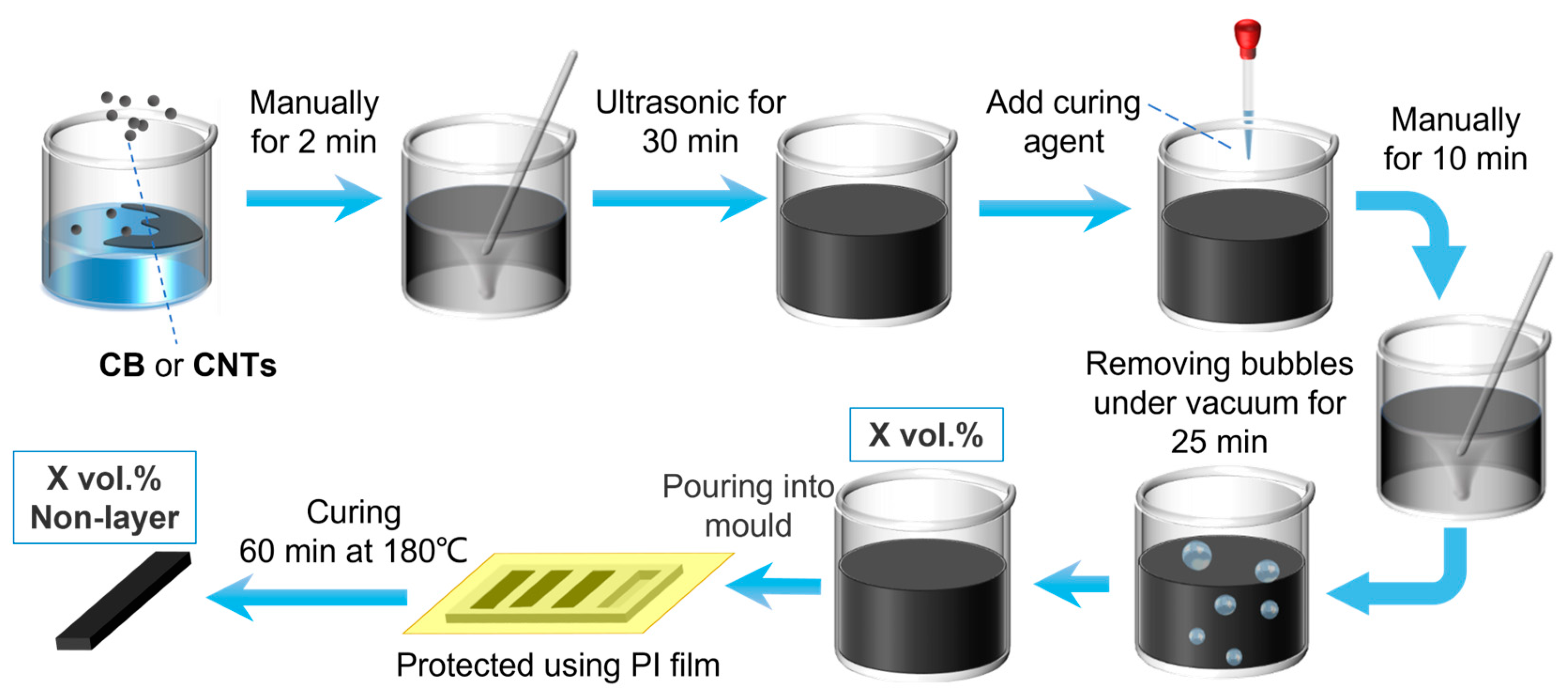
2.2. Experimental
3. Results and Discussion
3.1. Theory Results
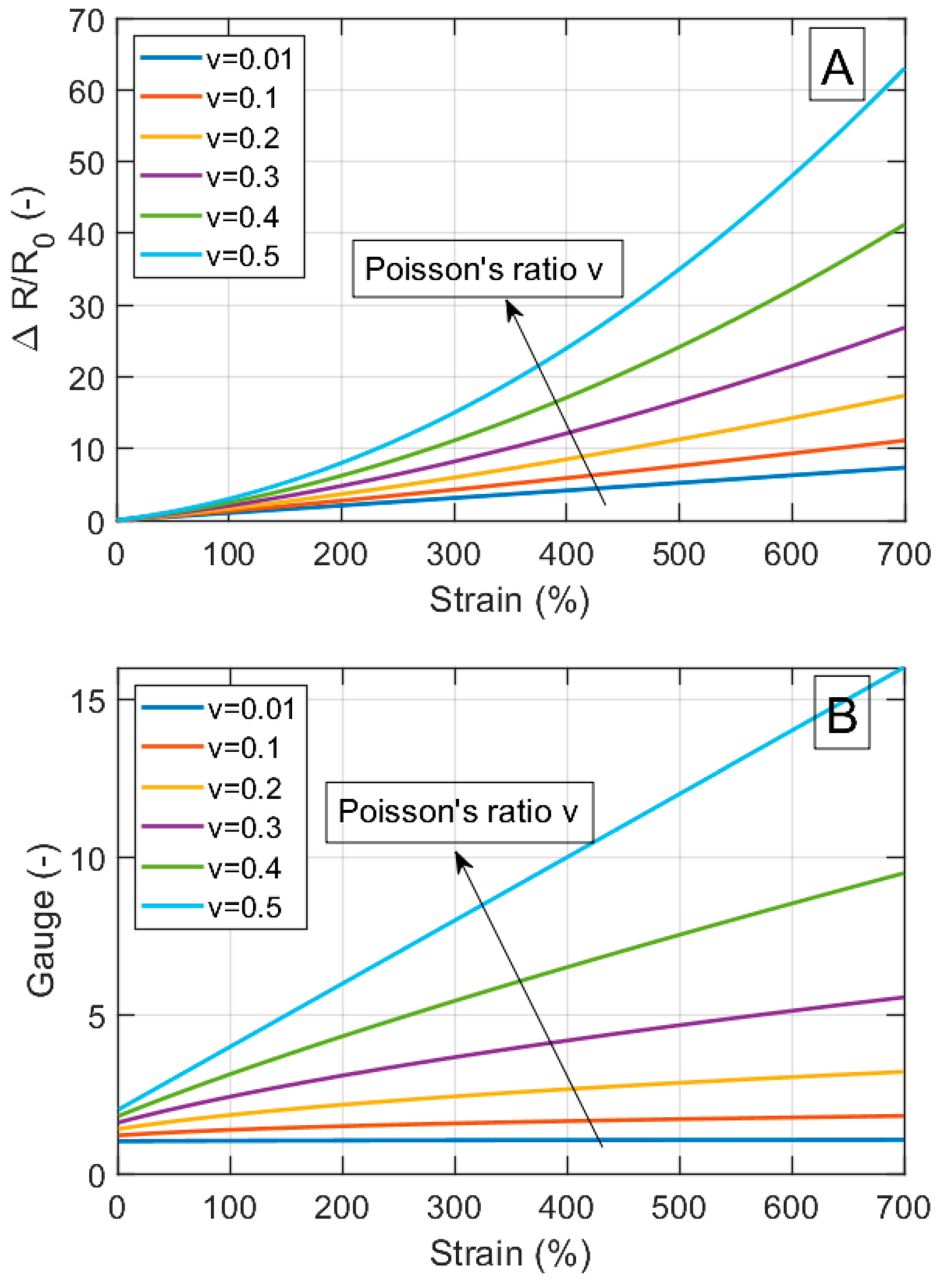
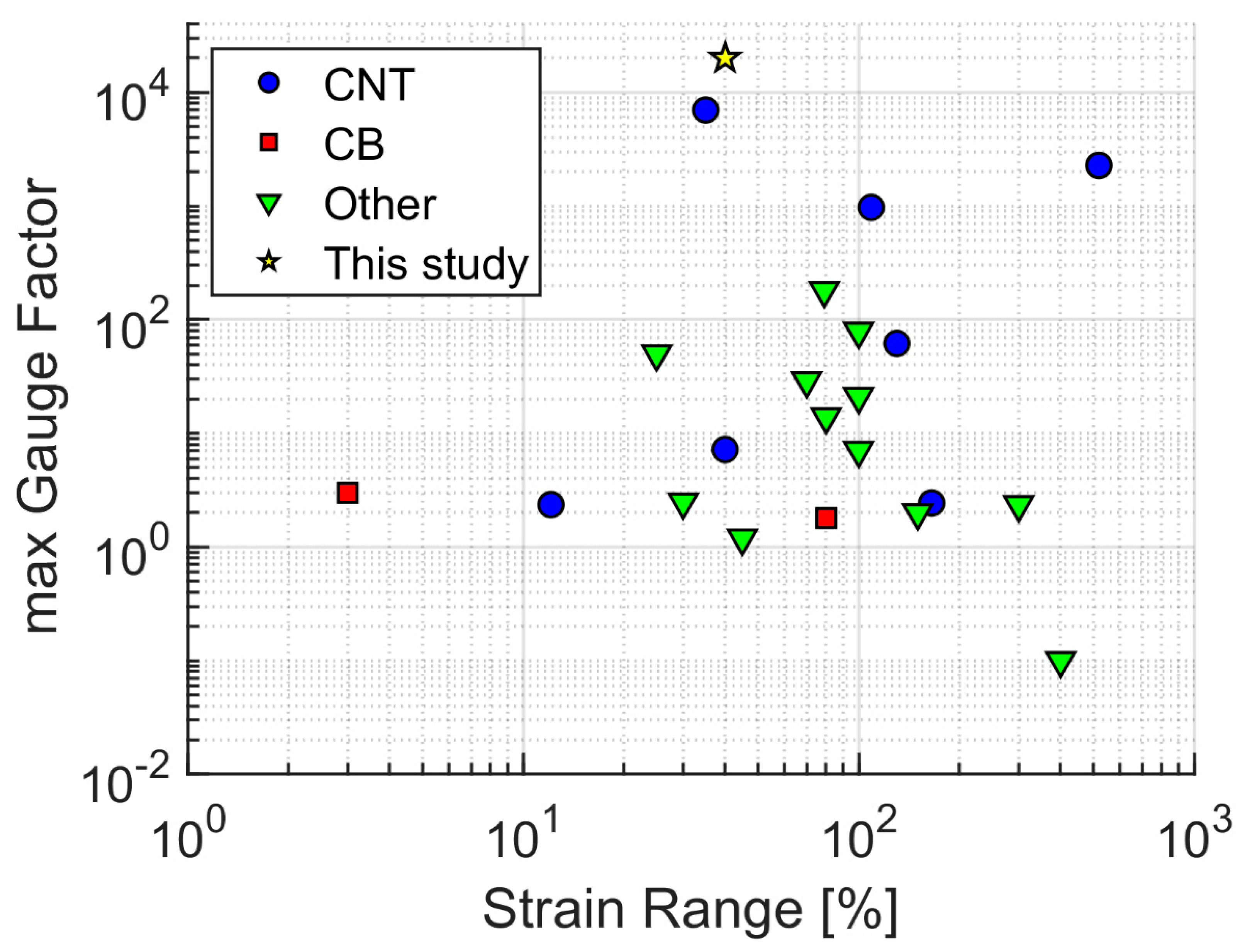
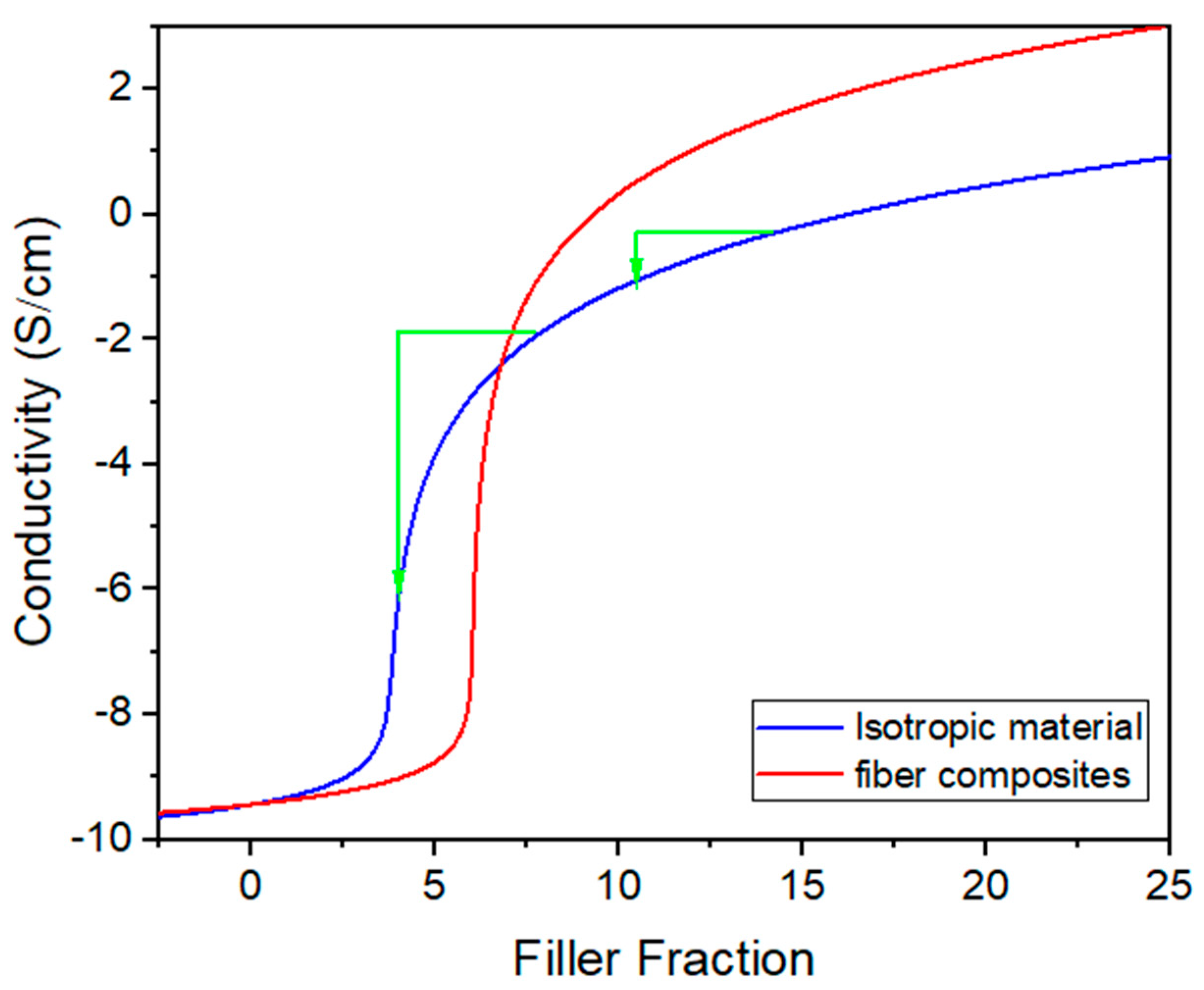
3.1.1. Geometrical Effects and Comparison with Literature Data
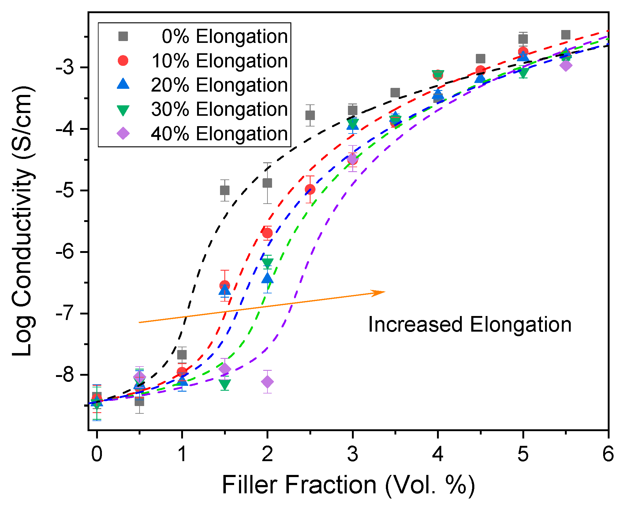
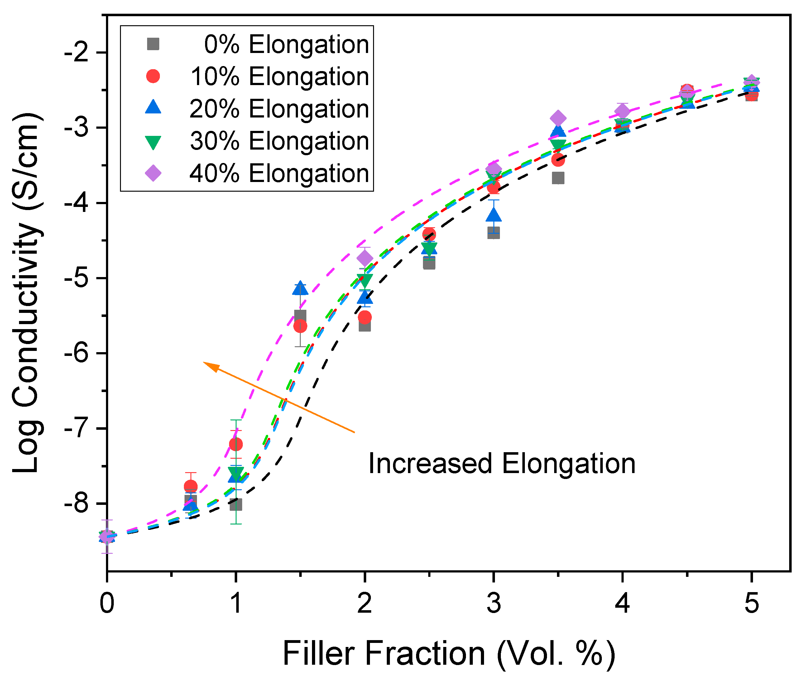
3.1.2. Strain Dependent Resistivity of Mixture Composites
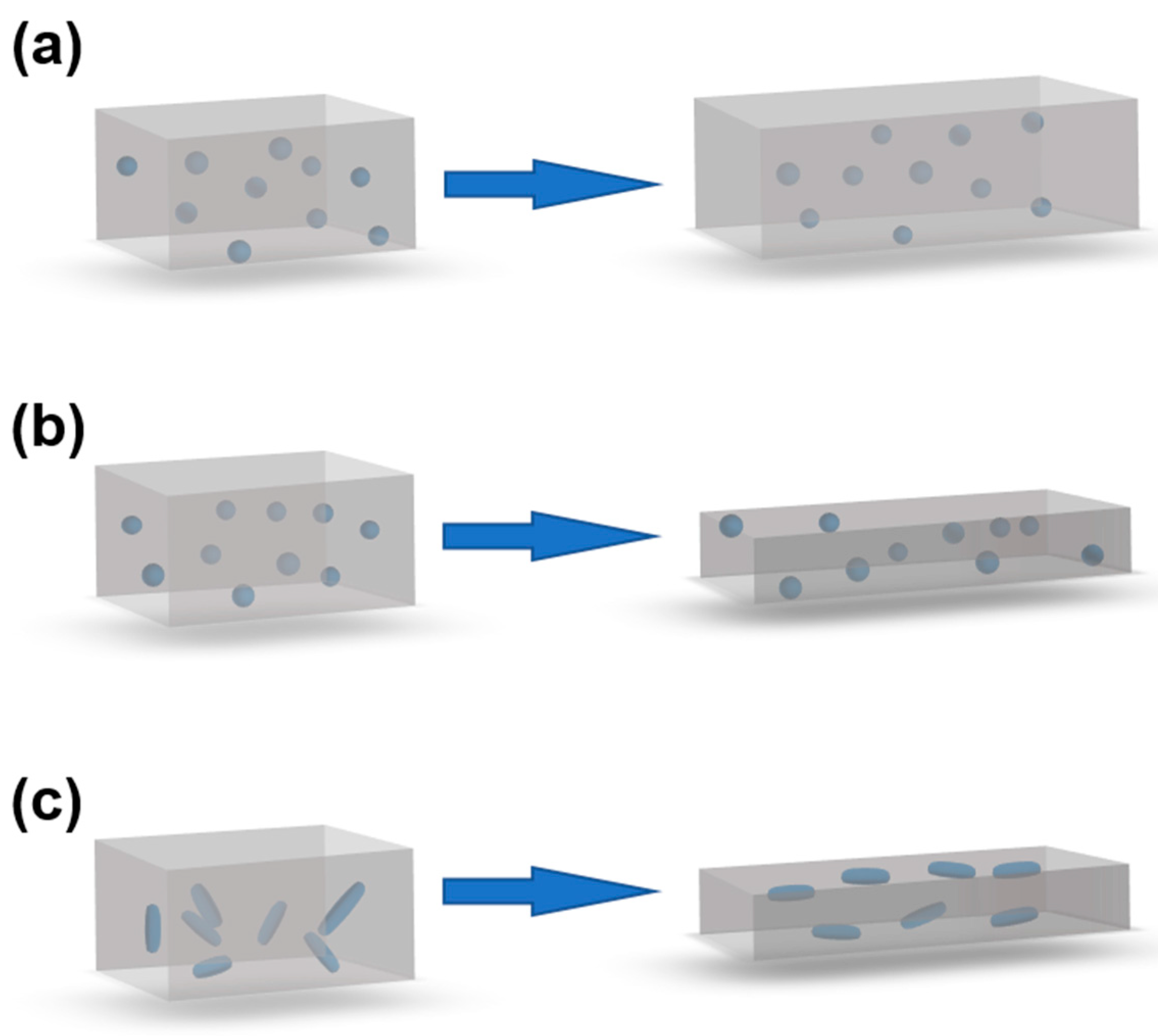
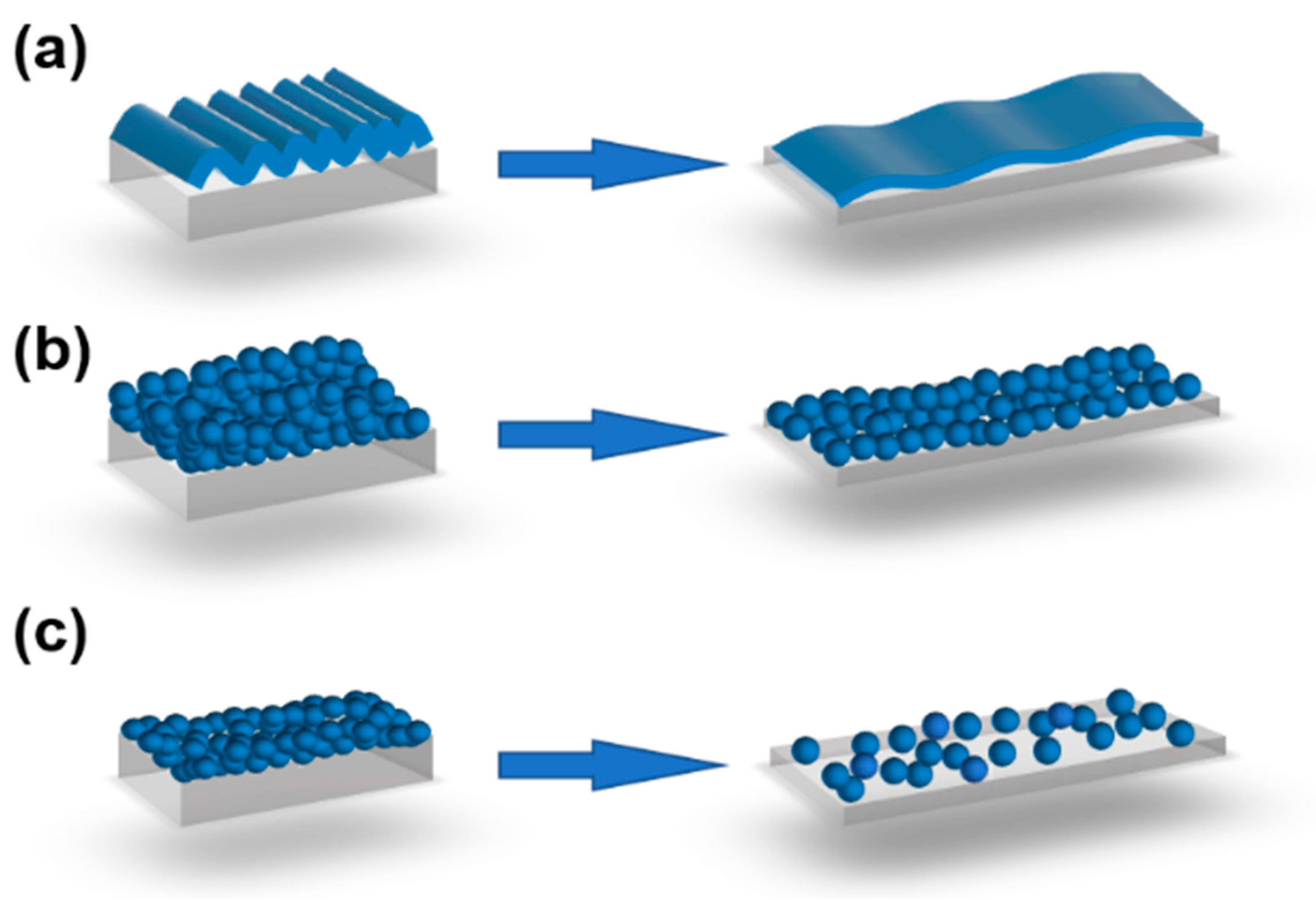
3.1.3. Strain Dependent Resistivity of Layered Composites
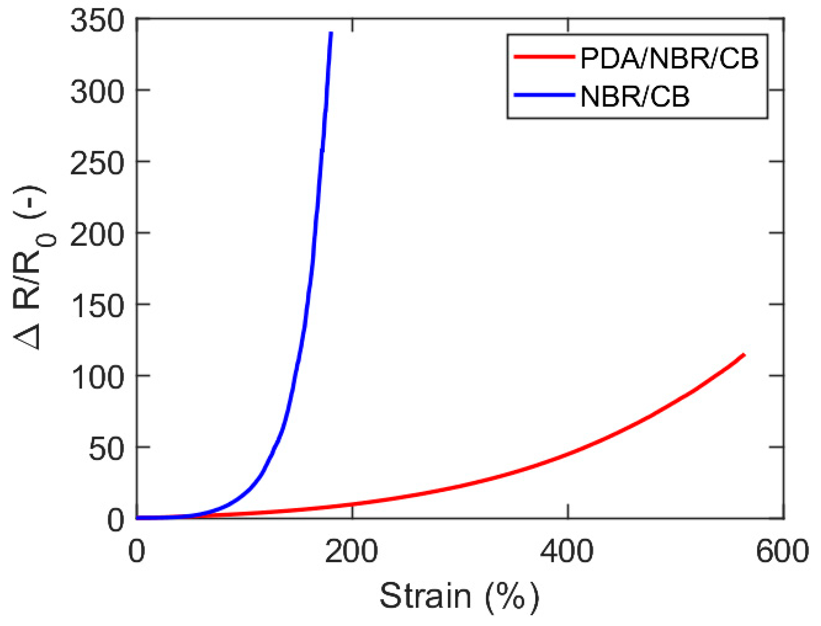
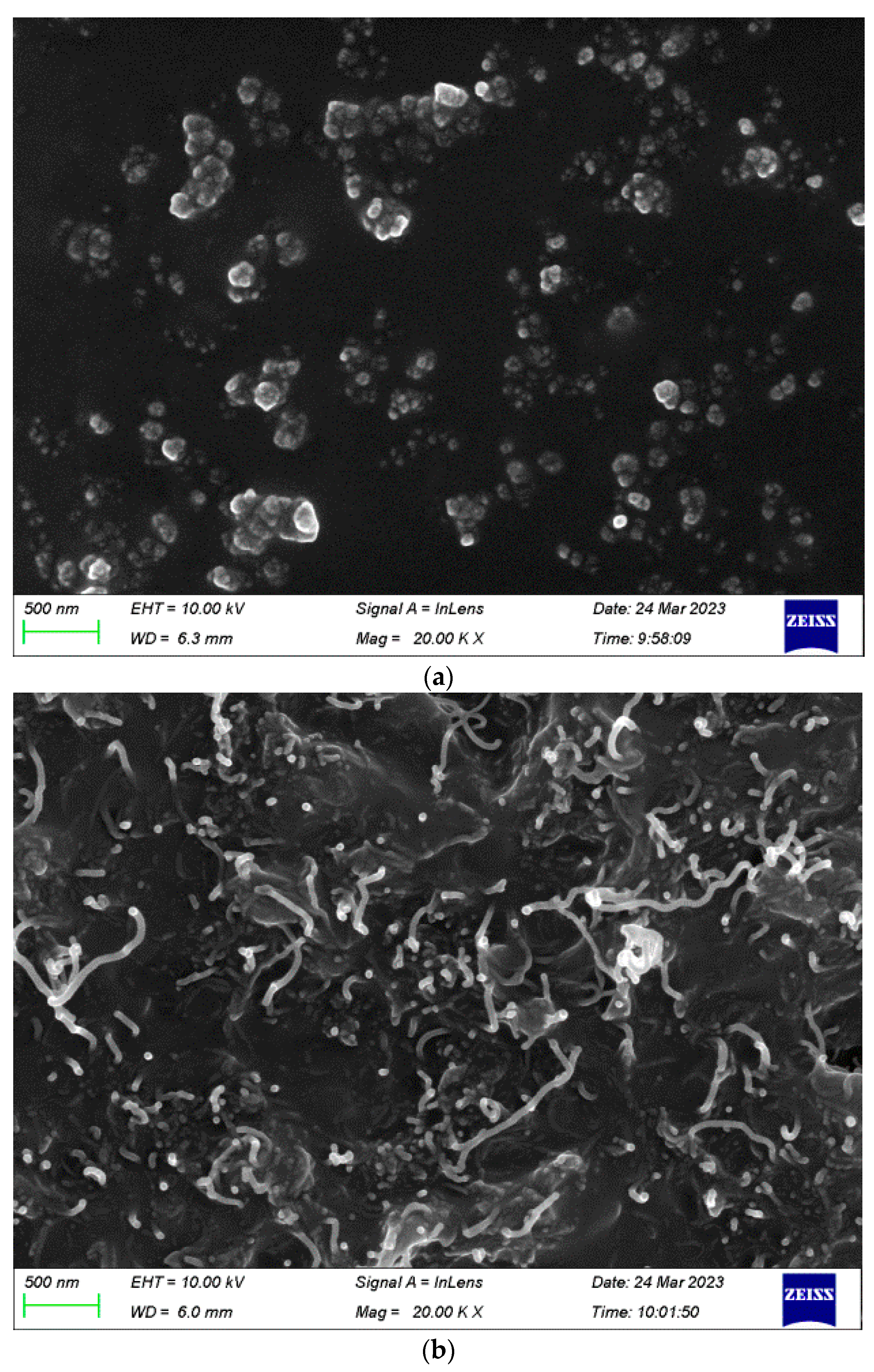
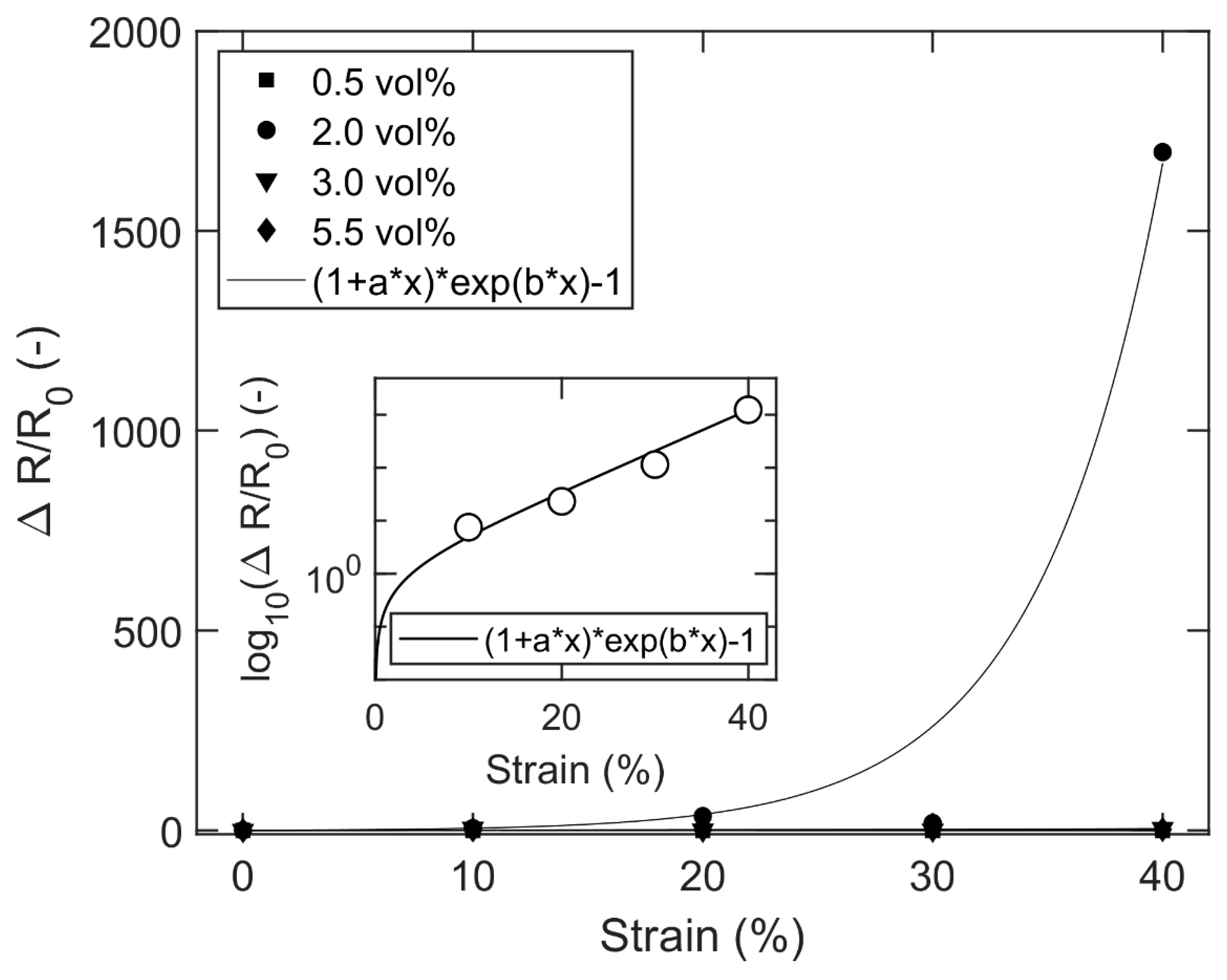
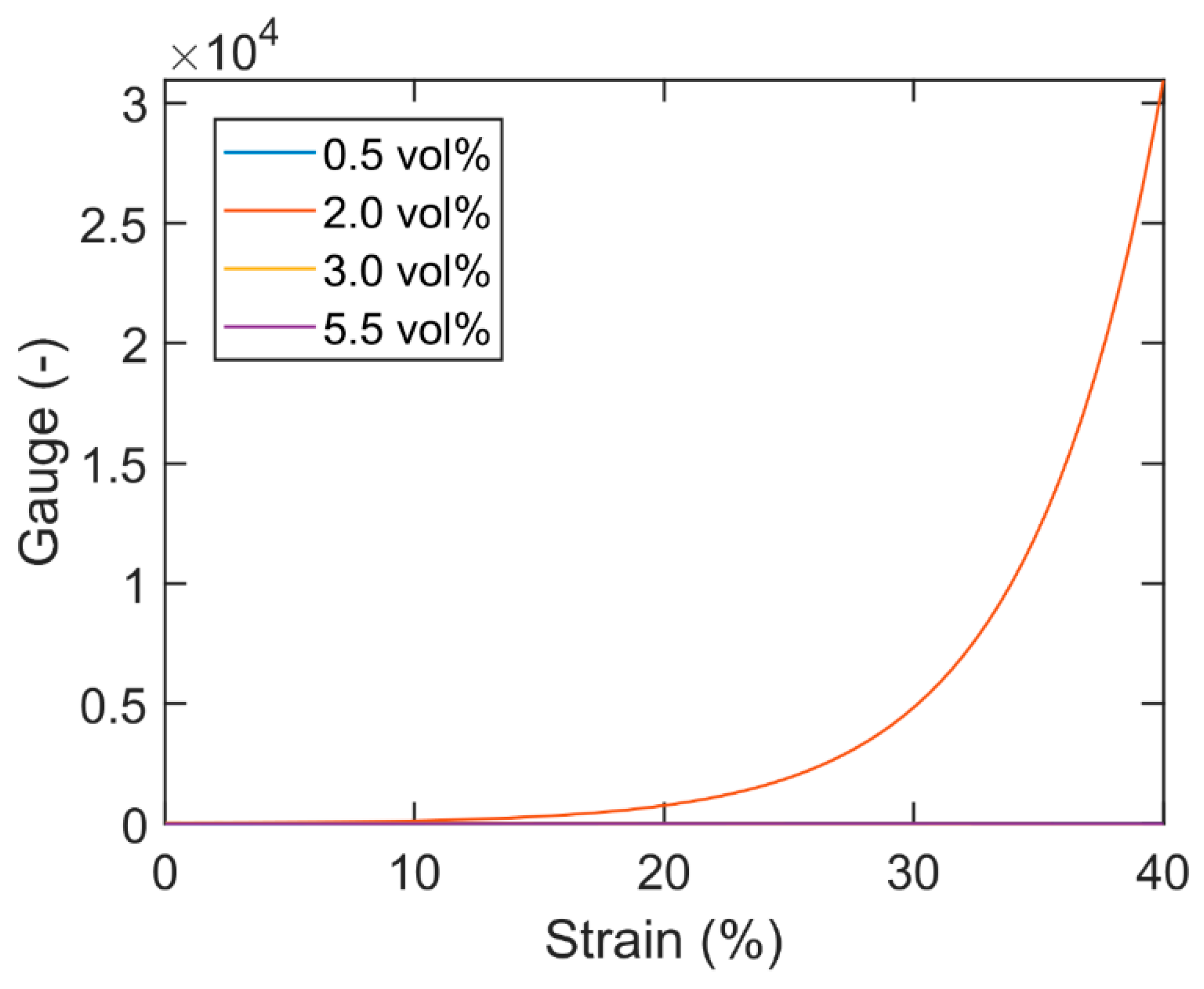
3.2. Experimental Results
4. Conclusions
Author Contributions
Funding
Data Availability Statement
Acknowledgments
Conflicts of Interest
References
- Xiang, S.; Chen, S.; Yao, M.; Zheng, F.; Lu, Q. Strain sensor based on a flexible polyimide ionogel for application in high-and low-temperature environments. J. Mater. Chem. C 2019, 7, 9625–9632. [Google Scholar] [CrossRef]
- Zou, Y.; Zhang, Y.; Hu, J. The Influence of the Initial Position and Length of Strain Sensing Yarn on the Sensing Performance of RFID-Based Textile Strain Sensor. In Proceedings of the Sino-Africa International Symposium on Textiles and Apparel, Shanghai, China, 3 November 2021; pp. 282–288. [Google Scholar]
- Zhao, K.; Niu, W.; Zhang, S. Highly stretchable, breathable and negative resistance variation textile strain sensor with excellent mechanical stability for wearable electronics. J. Mater. Sci. 2020, 55, 2439–2453. [Google Scholar] [CrossRef]
- Singh, R.; Singh, B.P.; Singh, A.P.; Kumar, V.; Kumar, R.; Bodaghi, M.; Serjouei, A.; Wei, Y. On 3D printing of low-cost sensors using recycled PET. Sādhanā 2022, 47, 260. [Google Scholar] [CrossRef]
- Sousa, E.A.; Lima, T.H.C.; Arlindo, E.P.S.; Sanches, A.O.; Sakamoto, W.K.; Fuzari-Junior, G.d.C. Multicomponent polyurethane–carbon black composite as piezoresistive sensor. Polym. Bull. 2020, 77, 3017–3031. [Google Scholar] [CrossRef]
- Li, X.; Koh, K.H.; Xue, J.; So, C.H.; Xiao, N.; Tin, C.; Wai, K.; Lai, C. 1D-2D nanohybrid-based textile strain sensor to boost multiscale deformative motion sensing performance. Nano Res. 2022, 15, 8398–8409. [Google Scholar] [CrossRef]
- Han, W.; Wu, Y.; Gong, H.; Liu, L.; Yan, J.; Li, M.; Long, Y.; Shen, G. Reliable sensors based on graphene textile with negative resistance variation in three dimensions. Nano Res. 2021, 14, 2810–2818. [Google Scholar] [CrossRef]
- Li, S.; Liu, G.; Wen, H.; Liu, G.; Wang, H.; Ye, M.; Yang, Y.; Guo, W.; Liu, Y. A Skin-Like Pressure-and Vibration-Sensitive Tactile Sensor Based on Polyacrylamide/Silk Fibroin Elastomer. Adv. Funct. Mater. 2022, 32, 2111747. [Google Scholar] [CrossRef]
- Liu, X.; Guo, R.; Li, R.; Liu, H.; Fan, Z.; Yang, Y.; Lin, Z. Effect of the Processing on the Resistance–Strain Response of Multiwalled Carbon Nanotube/Natural Rubber Composites for Use in Large Deformation Sensors. Nanomaterials 2021, 11, 1845. [Google Scholar] [CrossRef]
- Fan, M.; Wu, L.; Hu, Y.; Qu, M.; Yang, S.; Tang, P.; Pan, L.; Wang, H.; Bin, Y. A highly stretchable natural rubber/buckypaper/natural rubber (NR/N-BP/NR) sandwich strain sensor with ultrahigh sensitivity. Adv. Compos. Hybrid Mater. 2021, 4, 1039–1047. [Google Scholar] [CrossRef]
- Ding, H.; Luo, Z.; Kong, N.; Li, Z.; Zhao, P.; Zhang, J.; Tao, J. Constructing conductive titanium carbide nanosheet (MXene) network on natural rubber foam framework for flexible strain sensor. J. Mater. Sci. Mater. Electron. 2022, 33, 15563–15573. [Google Scholar] [CrossRef]
- Qu, M.; Qin, Y.; Sun, Y.; Xu, H.; Schubert, D.W.; Zheng, K.; Xu, W.; Nilsson, F. Biocompatible, flexible strain sensor fabricated with polydopamine-coated nanocomposites of nitrile rubber and carbon black. ACS Appl. Mater. Interfaces 2020, 12, 42140–42152. [Google Scholar] [CrossRef]
- Qu, M.; Li, D.; Qin, T.; Luo, Z.; Liu, X.; Nilsson, F.; Gao, Q.; Zheng, Z.; Qin, Y. Carbon Black Nanoparticle/Polydopamine-Coated Core-Spun Yarns for Flexible Strain Sensors. ACS Appl. Nano Mater. 2022, 5, 16996–17003. [Google Scholar] [CrossRef]
- Azizkhani, M.; Kadkhodapour, J.; Rastgordani, S.; Anaraki, A.; Shirkavand Hadavand, B. Highly sensitive, stretchable chopped carbon fiber/silicon rubber based sensors for human joint motion detection. Fibers Polym. 2019, 20, 35–44. [Google Scholar] [CrossRef]
- Zhao, C.; Xia, Z.; Wang, X.; Nie, J.; Huang, P.; Zhao, S. 3D-printed highly stable flexible strain sensor based on silver-coated-glass fiber-filled conductive silicon rubber. Mater. Des. 2020, 193, 108788. [Google Scholar] [CrossRef]
- Luo, W.; Xia, Z.; Zhou, W.; Wei, X.; Huang, P. An embedded printed flexible strain resistance sensor via micro-structure design on graphene-filled conductive silicon rubber. Smart Mater. Struct. 2022, 31, 115017. [Google Scholar] [CrossRef]
- Zhang, K.; Wang, Z.; Liu, Y.; Zhao, H.; Gao, C.; Wu, Y. Cephalopods-inspired repairable MWCNTs/PDMS conductive elastomers for sensitive strain sensor. Chin. J. Polym. Sci. 2022, 40, 384–393. [Google Scholar] [CrossRef]
- Ryu, C.; Park, J.; Jung, S.I.; Jang, I.R.; Kim, H.J. Measurement of Pulsating Flow Using a Self-Attachable Flexible Strain Sensor Based on Adhesive PDMS and CNT. Chemosensors 2022, 10, 187. [Google Scholar] [CrossRef]
- Liu, L.; Zhang, X.; Xiang, D.; Wu, Y.; Sun, D.; Shen, J.; Wang, M.; Zhao, C.; Li, H.; Li, Z. Highly stretchable, sensitive and wide linear responsive fabric-based strain sensors with a self-segregated carbon nanotube (CNT)/Polydimethylsiloxane (PDMS) coating. Prog. Nat. Sci. Mater. Int. 2022, 32, 34–42. [Google Scholar] [CrossRef]
- Zhang, M.; Wang, M.; Zhang, M.; Gao, Q.; Feng, X.; Zhang, Y.; Hu, J.; Wu, G. Stretchable conductive Ni@ Fe3O4@ Polyester fabric strain sensor with negative resistance variation and electromagnetic interference shielding. Org. Electron. 2020, 81, 105677. [Google Scholar] [CrossRef]
- Qin, Y.; Qu, M.; Pan, Y.; Zhang, C.; Schubert, D.W. Fabrication, characterization and modelling of triple hierarchic PET/CB/TPU composite fibres for strain sensing. Compos. Part A Appl. Sci. Manuf. 2020, 129, 105724. [Google Scholar] [CrossRef]
- Wang, H.; Zhao, Z.; Liu, P.; Guo, X. Laser-induced porous graphene on Polyimide/PDMS composites and its kirigami-inspired strain sensor. Theor. Appl. Mech. Lett. 2021, 11, 100240. [Google Scholar] [CrossRef]
- Huang, Y.; Wang, Y.; Gao, L.; He, X.; Liu, P.; Liu, C. Characterization of stretchable SWCNTs/Lycra fabric electrode with dyeing process. J. Mater. Sci. Mater. Electron. 2017, 28, 4279–4287. [Google Scholar] [CrossRef]
- Siavashani, V.S.; Gursoy, N.C.; Montazer, M.; Altay, P. Stretchable Electromagnetic Interference Shielding Textile Using Conductive Polymers and Metal Nanoparticles. Fibers Polym. 2022, 23, 2748–2759. [Google Scholar] [CrossRef]
- Wang, H.; Xue, P.; Zhu, W. An Integrated Numerical Method to Predict the Strain Sensing Behavior of Flexible Conductive Fibers under Electric–Thermal Conditions. J. Mater. Eng. Perform. 2019, 28, 3309–3319. [Google Scholar] [CrossRef]
- Grammatikos, S.A.; Dahl, M.M.; Brøndbo, V.S.; La Rosa, A.D. On the Use of Carbon Nanotubes to Develop Durable Structural Electrodes for Self-Sensing Applications. In Key Engineering Materials; Trans Tech Publications Ltd.: Bäch, Switzerland, 2020; pp. 458–463. [Google Scholar]
- He, Y.; Zhou, M.; Mahmoud, M.; Lu, X.; He, G.; Zhang, L.; Huang, M.; Elnaggar, A.Y.; Lei, Q.; Liu, H. Multifunctional wearable strain/pressure sensor based on conductive carbon nanotubes/silk nonwoven fabric with high durability and low detection limit. Adv. Compos. Hybrid Mater. 2022, 5, 1939–1950. [Google Scholar] [CrossRef]
- Chu, J.-M.; Claus, B.; Chen, W. Mechanical properties of transgenic silkworm silk under high strain rate tensile loading. J. Dyn. Behav. Mater. 2017, 3, 538–547. [Google Scholar] [CrossRef]
- Zhang, L.; Wang, J.; Zhang, J.; Hou, L.; Ye, D.; Jiang, X. Preparation of tough and anti-freezing hybrid double-network carboxymethyl chitosan/poly (acrylic amide) hydrogel and its application for flexible strain sensor. J. Mater. Sci. 2022, 57, 19666–19680. [Google Scholar] [CrossRef]
- Guo, Z.; Liu, Z.; Liu, W.; Tang, A.; Chen, W.; Luo, S. Multifunctional flexible polyvinyl alcohol nanocomposite hydrogel for stress and strain sensor. J. Nanoparticle Res. 2021, 23, 222. [Google Scholar] [CrossRef]
- Bai, J.; Wang, R.; Ju, M.; Zhou, J.; Zhang, L.; Jiao, T. Facile preparation and high performance of wearable strain sensors based on ionically cross-linked composite hydrogels. Sci. China Mater. 2020, 64, 942–952. [Google Scholar] [CrossRef]
- Chang, J.; Zhang, Z.; Jia, F.; Gao, G. Ionic conductive hydrogels toughened by latex particles for strain sensors. Sci. China Technol. Sci. 2021, 64, 827–835. [Google Scholar] [CrossRef]
- Wang, X.; Liu, X.; Schubert, D.W. Highly sensitive ultrathin flexible thermoplastic polyurethane/carbon black fibrous film strain sensor with adjustable scaffold networks. Nano-Micro Lett. 2021, 13, 64. [Google Scholar] [CrossRef] [PubMed]
- Qu, M.; Qin, Y.; Xu, W.; Zheng, Z.; Xu, H.; Schubert, D.W.; Gao, Q. Electrically conductive NBR/CB flexible composite film for ultrastretchable strain sensors: Fabrication and modeling. Appl. Nanosci. 2021, 11, 429–439. [Google Scholar] [CrossRef]
- Hu, M.; Gao, Y.; Jiang, Y.; Zeng, H.; Zeng, S.; Zhu, M.; Xu, G.; Sun, L. High-performance strain sensors based on bilayer carbon black/PDMS hybrids. Adv. Compos. Hybrid Mater. 2021, 4, 514–520. [Google Scholar] [CrossRef]
- Chavali, M.S.; Nikolova, M.P. Metal oxide nanoparticles and their applications in nanotechnology. SN Appl. Sci. 2019, 1, 607. [Google Scholar] [CrossRef] [Green Version]
- Patial, P.; Deshwal, M. Selectivity and sensitivity property of metal oxide semiconductor based gas sensor with dopants variation: A review. Trans. Electr. Electron. Mater. 2021, 23, 6–18. [Google Scholar] [CrossRef]
- Singh, K.; Singh, R.C. Highly sensitive and selective ethanol gas sensor based on Ga-doped NiO nanoparticles. J. Mater. Sci. Mater. Electron. 2021, 32, 11274–11290. [Google Scholar]
- Yang, W.; Qin, Y.; Wang, Z.; Yu, T.; Ge, Z. Recent Advances in the Development of Flexible Sensors: Mechanisms, Materials, Performance Optimization, and Applications. J. Electron. Mater. 2022, 51, 6735–6769. [Google Scholar] [CrossRef]
- Shukla, P.; Saxena, P. Polymer nanocomposites in sensor applications: A review on present trends and future scope. Chin. J. Polym. Sci. 2021, 39, 665–691. [Google Scholar] [CrossRef]
- Lee, J.; Choi, Y.; Park, B.J.; Han, J.W.; Lee, H.-S.; Park, J.H.; Lee, W. Precise control of surface oxygen vacancies in ZnO nanoparticles for extremely high acetone sensing response. J. Adv. Ceram. 2022, 11, 769–783. [Google Scholar] [CrossRef]
- Xiong, C.; Xu, J.; Han, Q.; Qin, C.; Dai, L.; Ni, Y. Construction of flexible cellulose nanofiber fiber@ graphene quantum dots hybrid film applied in supercapacitor and sensor. Cellulose 2021, 28, 10359–10372. [Google Scholar] [CrossRef]
- Chen, X.; Wang, T.; Shi, J.; Lv, W.; Han, Y.; Zeng, M.; Yang, J.; Hu, N.; Su, Y.; Wei, H. A novel artificial neuron-like gas sensor constructed from CuS quantum dots/Bi 2 S 3 nanosheets. Nano-Micro Lett. 2022, 14, 8. [Google Scholar] [CrossRef] [PubMed]
- Li, B.; Zhang, J.; Luo, Z.; Duan, X.; Huang, W.-Q.; Hu, W.; Huang, G. Amorphous B-doped graphitic carbon nitride quantum dots with high photoluminescence quantum yield of near 90% and their sensitive detection of Fe2+/Cd2+. Sci. China Mater. 2021, 64, 3037–3050. [Google Scholar] [CrossRef]
- Ahmed, F.; Soomro, A.M.; Ashraf, H.; Rahim, A.; Asif, A.; Jawed, B.; Waqas, M.; Choi, K.H. Robust ultrasensitive stretchable sensor for wearable and high-end robotics applications. J. Mater. Sci. Mater. Electron. 2022, 33, 26447–26463. [Google Scholar] [CrossRef]
- Xu, X.; Chen, Y.; He, P.; Wang, S.; Ling, K.; Liu, L.; Lei, P.; Huang, X.; Zhao, H.; Cao, J. Wearable CNT/Ti3C2T x MXene/PDMS composite strain sensor with enhanced stability for real-time human healthcare monitoring. Nano Res. 2021, 14, 2875–2883. [Google Scholar] [CrossRef]
- Xiang, D.; Liu, L.; Xu, F.; Li, Y.; Harkin-Jones, E.; Wu, Y.; Zhao, C.; Li, H.; Li, Z.; Wang, P. Highly Sensitive Flexible Strain Sensor Based on a Double-percolation Structured Elastic Fiber of Carbon Nanotube (CNT)/Styrene Butadiene Styrene (SBS)@ Thermoplastic Polyurethane (TPU) for Human Motion and Tactile Recognition. Appl. Compos. Mater. 2023, 30, 307–322. [Google Scholar] [CrossRef]
- Singh, K.; Gupta, M.; Tripathi, C. Fabrication of flexible and sensitive laser-patterned serpentine-structured graphene–CNT paper for strain sensor applications. Appl. Phys. A 2022, 128, 1131. [Google Scholar] [CrossRef]
- Wang, Q.; Liu, J.; Ran, X.; Zhang, D.; Shen, G.; Miao, M. High-performance flexible self-powered strain sensor based on carbon nanotube/ZnSe/CoSe 2 nanocomposite film electrodes. Nano Res. 2022, 15, 170–178. [Google Scholar] [CrossRef]
- Kang, D.-H.; Lee, J.-H.; Lee, J.-W.; Cho, H.-S.; Park, S.-H.; Lee, K.-H.; Kang, S.-J. Conditions for CNT–Coated Textile Sensors Applied to Wearable Platforms to Monitor Limb Joint Motion. J. Med. Syst. 2021, 45, 41. [Google Scholar] [CrossRef]
- Bi, P.; Zhang, M.; Li, S.; Lu, H.; Wang, H.; Liang, X.; Liang, H.; Zhang, Y. Ultra-sensitive and wide applicable strain sensor enabled by carbon nanofibers with dual alignment for human machine interfaces. Nano Res. 2022, 16, 4093–4099. [Google Scholar] [CrossRef]
- Cha, S.; Kim, I.; Lee, E.; Jang, E.; Cho, G. AgNW treated PU nanofiber/PDMS composites as wearable strain sensors for joint flexion monitoring. Fibers Polym. 2020, 21, 2479–2484. [Google Scholar] [CrossRef]
- Yan, T.; Wu, Y.; Pan, Z. Anisotropy of resistance-type strain sensing networks based on aligned carbon nanofiber membrane. J. Mater. Sci. 2021, 56, 6292–6305. [Google Scholar] [CrossRef]
- Luo, W.; Charara, M.; Saha, M.C.; Liu, Y. Fabrication and characterization of porous CNF/PDMS nanocomposites for sensing applications. Appl. Nanosci. 2019, 9, 1309–1317. [Google Scholar] [CrossRef]
- Zhang, F.; Hu, H.; Hu, S.; Yue, J. Significant strain-rate dependence of sensing behavior in TiO2@ carbon fibre/PDMS composites for flexible strain sensors. J. Adv. Ceram. 2021, 10, 1350–1359. [Google Scholar] [CrossRef]
- Zhu, J.; Song, Y.; Xue, X.; Liu, Z.; Mao, Q.; Jia, Z. An eco-friendly and highly sensitive loofah@ CF/CNT 3D piezoresistive sensor for human activity monitoring and mechanical control. Sci. China Technol. Sci. 2022, 65, 2667–2674. [Google Scholar] [CrossRef]
- Zhang, X.M.; Yang, X.-L.; Wang, B. Flexible and stretchable sensors composited by carbon fiber/silver nanopowders and PDMS for strain detection. J. Mater. Sci. Mater. Electron. 2022, 33, 13426–13434. [Google Scholar] [CrossRef]
- Huang, Y.; Xiang, Y.; Ren, W.; Li, F.; Li, C.; Yang, T. Enhancing the sensitivity of crack-based strain sensor assembled by functionalized graphene for human motion detection. Sci. China Technol. Sci. 2021, 64, 1805–1813. [Google Scholar] [CrossRef]
- Lu, S.; Ma, J.; Ma, K.; Wang, X.; Wang, S.; Yang, X.; Tang, H. Highly sensitive graphene platelets and multi-walled carbon nanotube-based flexible strain sensor for monitoring human joint bending. Appl. Phys. A 2019, 125, 471. [Google Scholar] [CrossRef]
- Nie, M.; Xia, Y.-H.; Yang, H.-S. A flexible and highly sensitive graphene-based strain sensor for structural health monitoring. Clust. Comput. 2019, 22, 8217–8224. [Google Scholar] [CrossRef]
- Htwe, Y.; Mariatti, M.; Chin, S. Fabrication of graphene by electrochemical intercalation method and performance of graphene/PVA composites as stretchable strain sensor. Arab. J. Sci. Eng. 2020, 45, 7677–7689. [Google Scholar] [CrossRef]
- Hieu, N.H.; Nhiem, L.T. Utilization of Multilayered Structure of Gold Nanoparticles and Graphene Oxide as Highly Sensitive Strain Sensor. J. Electron. Mater. 2022, 51, 5601–5608. [Google Scholar] [CrossRef]
- Yang, Y.; Shen, H.; Yang, Z.; Yang, J.; Wang, Z.; Gao, K. Highly flexible and sensitive wearable strain and pressure sensor based on porous graphene paper for human motion. J. Mater. Sci. Mater. Electron. 2022, 33, 17637–17648. [Google Scholar] [CrossRef]
- Sun, T.; Jiang, Y.; Duan, Z.; Yuan, Z.; Wang, Y.; Tai, H. Wearable and washable textile-based strain sensors via a single-step, environment-friendly method. Sci. China Technol. Sci. 2021, 64, 441–450. [Google Scholar] [CrossRef]
- Yang, Y.; Shen, H.; Yang, Z.; Yang, J.; Wang, Z.; Gao, K. Macroporous and free-shape reduced graphene oxide paper as sensitive wearable pressure and strain sensors. Appl. Phys. A 2022, 128, 948. [Google Scholar] [CrossRef]
- Sun, Q.J.; Lai, Q.T.; Tang, Z.; Tang, X.G.; Zhao, X.H.; Roy, V.A. Advanced Functional Composite Materials toward E-Skin for Health Monitoring and Artificial Intelligence. Adv. Mater. Technol. 2023, 8, 2201088. [Google Scholar] [CrossRef]
- Sekine, T.; Abe, M.; Muraki, K.; Tachibana, S.; Wang, Y.F.; Hong, J.; Takeda, Y.; Kumaki, D.; Tokito, S. Microporous induced fully printed pressure sensor for wearable soft robotics machine interfaces. Adv. Intell. Syst. 2020, 2, 2000179. [Google Scholar] [CrossRef]
- Sim, K.; Rao, Z.; Kim, H.J.; Thukral, A.; Shim, H.; Yu, C. Fully rubbery integrated electronics from high effective mobility intrinsically stretchable semiconductors. Sci. Adv. 2019, 5, eaav5749. [Google Scholar] [CrossRef] [Green Version]
- Peng, S.; Yu, Y.; Wu, S.; Wang, C.H. Conductive polymer nanocomposites for stretchable electronics: Material selection, design, and applications. ACS Appl. Mater. Interfaces 2021, 13, 43831–43854. [Google Scholar] [CrossRef]
- Wang, C.; Yokota, T.; Someya, T. Natural biopolymer-based biocompatible conductors for stretchable bioelectronics. Chem. Rev. 2021, 121, 2109–2146. [Google Scholar] [CrossRef]
- Kim, D.C.; Shim, H.J.; Lee, W.; Koo, J.H.; Kim, D.H. Stretchable Electronics: Material-Based Approaches for the Fabrication of Stretchable Electronics (Adv. Mater. 15/2020). Adv. Mater. 2020, 32, 2070118. [Google Scholar] [CrossRef] [Green Version]
- Li, W.; Xu, F.; Liu, W.; Gao, Y.; Zhang, K.; Zhang, X.; Qiu, Y. Flexible strain sensor based on aerogel-spun carbon nanotube yarn with a core-sheath structure. Compos. Part A Appl. Sci. Manuf. 2018, 108, 107–113. [Google Scholar] [CrossRef]
- Kong, J.-H.; Jang, N.-S.; Kim, S.-H.; Kim, J.-M. Simple and rapid micropatterning of conductive carbon composites and its application to elastic strain sensors. Carbon 2014, 77, 199–207. [Google Scholar] [CrossRef]
- Zhao, J.; Dai, K.; Liu, C.; Zheng, G.; Wang, B.; Liu, C.; Chen, J.; Shen, C. A comparison between strain sensing behaviors of carbon black/polypropylene and carbon nanotubes/polypropylene electrically conductive composites. Compos. Part A Appl. Sci. Manuf. 2013, 48, 129–136. [Google Scholar] [CrossRef]
- Wu, J.; Wang, Z.; Liu, W.; Wang, L.; Xu, F. Bioinspired superelastic electroconductive fiber for wearable electronics. ACS Appl. Mater. Interfaces 2019, 11, 44735–44741. [Google Scholar] [CrossRef]
- Luo, J.; Gao, S.; Luo, H.; Wang, L.; Huang, X.; Guo, Z.; Lai, X.; Lin, L.; Li, R.K.; Gao, J. Superhydrophobic and breathable smart MXene-based textile for multifunctional wearable sensing electronics. Chem. Eng. J. 2021, 406, 126898. [Google Scholar] [CrossRef]
- Zheng, Y.; Li, Y.; Zhou, Y.; Dai, K.; Zheng, G.; Zhang, B.; Liu, C.; Shen, C. High-performance wearable strain sensor based on graphene/cotton fabric with high durability and low detection limit. ACS Appl. Mater. Interfaces 2019, 12, 1474–1485. [Google Scholar] [CrossRef]
- Zhang, W.; Liu, Q.; Chen, P. Flexible strain sensor based on carbon black/silver nanoparticles composite for human motion detection. Materials 2018, 11, 1836. [Google Scholar] [CrossRef] [Green Version]
- Li, T.; Li, J.; Zhong, A.; Han, F.; Sun, R.; Wong, C.-P.; Niu, F.; Zhang, G.; Jin, Y. A flexible strain sensor based on CNTs/PDMS microspheres for human motion detection. Sens. Actuators A Phys. 2020, 306, 111959. [Google Scholar] [CrossRef]
- Wang, Y.; Hao, J.; Huang, Z.; Zheng, G.; Dai, K.; Liu, C.; Shen, C. Flexible electrically resistive-type strain sensors based on reduced graphene oxide-decorated electrospun polymer fibrous mats for human motion monitoring. Carbon 2018, 126, 360–371. [Google Scholar] [CrossRef]
- Zhang, P.; Chen, Y.; Li, Y.; Zhang, Y.; Zhang, J.; Huang, L. A flexible strain sensor based on the porous structure of a carbon black/carbon nanotube conducting network for human motion detection. Sensors 2020, 20, 1154. [Google Scholar] [CrossRef] [Green Version]
- Li, M.; Li, H.; Zhong, W.; Zhao, Q.; Wang, D. Stretchable conductive polypyrrole/polyurethane (PPy/PU) strain sensor with netlike microcracks for human breath detection. ACS Appl. Mater. Interfaces 2014, 6, 1313–1319. [Google Scholar] [CrossRef]
- Yu, Y.; Luo, Y.; Guo, A.; Yan, L.; Wu, Y.; Jiang, K.; Li, Q.; Fan, S.; Wang, J. Flexible and transparent strain sensors based on super-aligned carbon nanotube films. Nanoscale 2017, 9, 6716–6723. [Google Scholar] [CrossRef] [PubMed]
- Park, J.J.; Hyun, W.J.; Mun, S.C.; Park, Y.T.; Park, O.O. Highly stretchable and wearable graphene strain sensors with controllable sensitivity for human motion monitoring. ACS Appl. Mater. Interfaces 2015, 7, 6317–6324. [Google Scholar] [CrossRef] [PubMed]
- Jeong, Y.R.; Park, H.; Jin, S.W.; Hong, S.Y.; Lee, S.S.; Ha, J.S. Highly stretchable and sensitive strain sensors using fragmentized graphene foam. Adv. Funct. Mater. 2015, 25, 4228–4236. [Google Scholar] [CrossRef]
- Yan, C.; Wang, J.; Kang, W.; Cui, M.; Wang, X.; Foo, C.Y.; Chee, K.J.; Lee, P.S. Highly stretchable piezoresistive graphene–nanocellulose nanopaper for strain sensors. Adv. Mater. 2014, 26, 2022–2027. [Google Scholar] [CrossRef]
- Qu, M.; Nilsson, F.; Schubert, D.W. Effect of filler orientation on the electrical conductivity of carbon Fiber/PMMA composites. Fibers 2018, 6, 3. [Google Scholar] [CrossRef] [Green Version]


| Resin | Poisson Ratios |
|---|---|
| PDMS | 0.498 |
| Polypropylene | 0.43 |
| TPU | 0.3897 |
| Natural rubber | 0.48 |
| PVC | 0.38 |
| Polycarbonate | 0.36 |
| Resin | Filler | Strain Range | Max. GF | Reference |
|---|---|---|---|---|
| Polyimide/PDMS | Graphene | 79 | 181 | 22 |
| Silk | CNT | 35 | 7000 | 27 |
| Aerogel | CNT | 12.1 | 2.36 | 72 |
| PDMS | CB | 80 | 1.8 | 73 |
| Polypropylene | CB | 3 | 3 | 74 |
| PDMS | CNT | 165 | 2.44 | 75 |
| PDMS | MXene | 45 | 1.2 | 76 |
| PDMS | Graphene | 30 | 2.49 | 77 |
| TPU | CB/AgNWs | 100 | 21.12 | 78 |
| PDMS | MWCNTs | 40 | 7.22 | 79 |
| TPU | RGO | 100 | 79 | 80 |
| PDMS | CB/CNT | 130 | 61.82 | 71 |
| PU | PPy | 300 | 2.36 | 82 |
| PDMS | SACNT | 400 | 0.1 | 83 |
| PDMS | Graphene | 150 | 2 | 84 |
| PDMS | FGF | 70 | 29 | 85 |
| PDMS | Nanopaper | 100 | 7.1 | 86 |
| Polyester fabric | Ni@Fe₃O₄ | 40 | - | 20 |
| Natural rubber | CNT | 109 | 974.2 | 9 |
| Natural rubber | CNT | 520 | 2280 | 10 |
| Natural rubber | MXene | 80 | 14 | 11 |
| Silicon Rubber | CCF | 25 | 50 | 14 |
| PDMS | CB (2.0 vol.%) | 40 | >20,000 | This study |
Disclaimer/Publisher’s Note: The statements, opinions and data contained in all publications are solely those of the individual author(s) and contributor(s) and not of MDPI and/or the editor(s). MDPI and/or the editor(s) disclaim responsibility for any injury to people or property resulting from any ideas, methods, instructions or products referred to in the content. |
© 2023 by the authors. Licensee MDPI, Basel, Switzerland. This article is an open access article distributed under the terms and conditions of the Creative Commons Attribution (CC BY) license (https://creativecommons.org/licenses/by/4.0/).
Share and Cite
Qu, M.; Xie, Z.; Liu, S.; Zhang, J.; Peng, S.; Li, Z.; Lin, C.; Nilsson, F. Electric Resistance of Elastic Strain Sensors—Fundamental Mechanisms and Experimental Validation. Nanomaterials 2023, 13, 1813. https://doi.org/10.3390/nano13121813
Qu M, Xie Z, Liu S, Zhang J, Peng S, Li Z, Lin C, Nilsson F. Electric Resistance of Elastic Strain Sensors—Fundamental Mechanisms and Experimental Validation. Nanomaterials. 2023; 13(12):1813. https://doi.org/10.3390/nano13121813
Chicago/Turabian StyleQu, Muchao, Zixin Xie, Shuiyan Liu, Jinzhu Zhang, Siyao Peng, Zhitong Li, Cheng Lin, and Fritjof Nilsson. 2023. "Electric Resistance of Elastic Strain Sensors—Fundamental Mechanisms and Experimental Validation" Nanomaterials 13, no. 12: 1813. https://doi.org/10.3390/nano13121813