
Measurement of Slips at Contact Interfaces Using a Self-Powered Sensor Based on Triboelectric Nanogenerators

Abstract
:1. Introduction
2. Materials and Methods
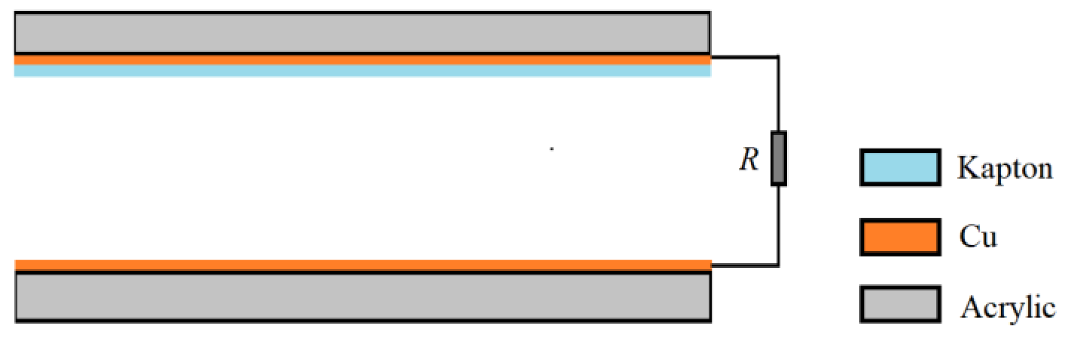
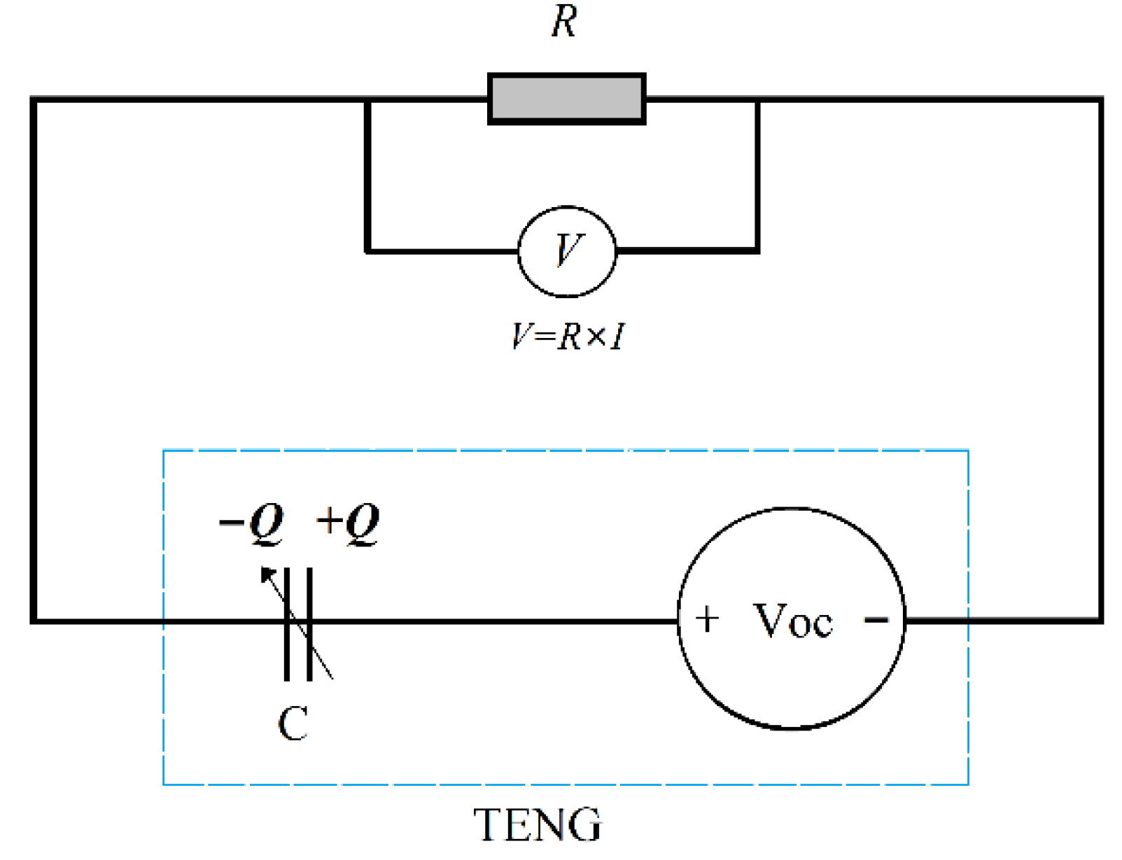
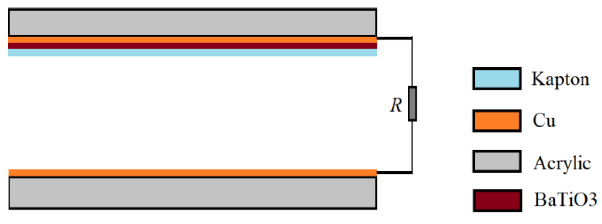
2.1. Principle of Self-Powered Sensor
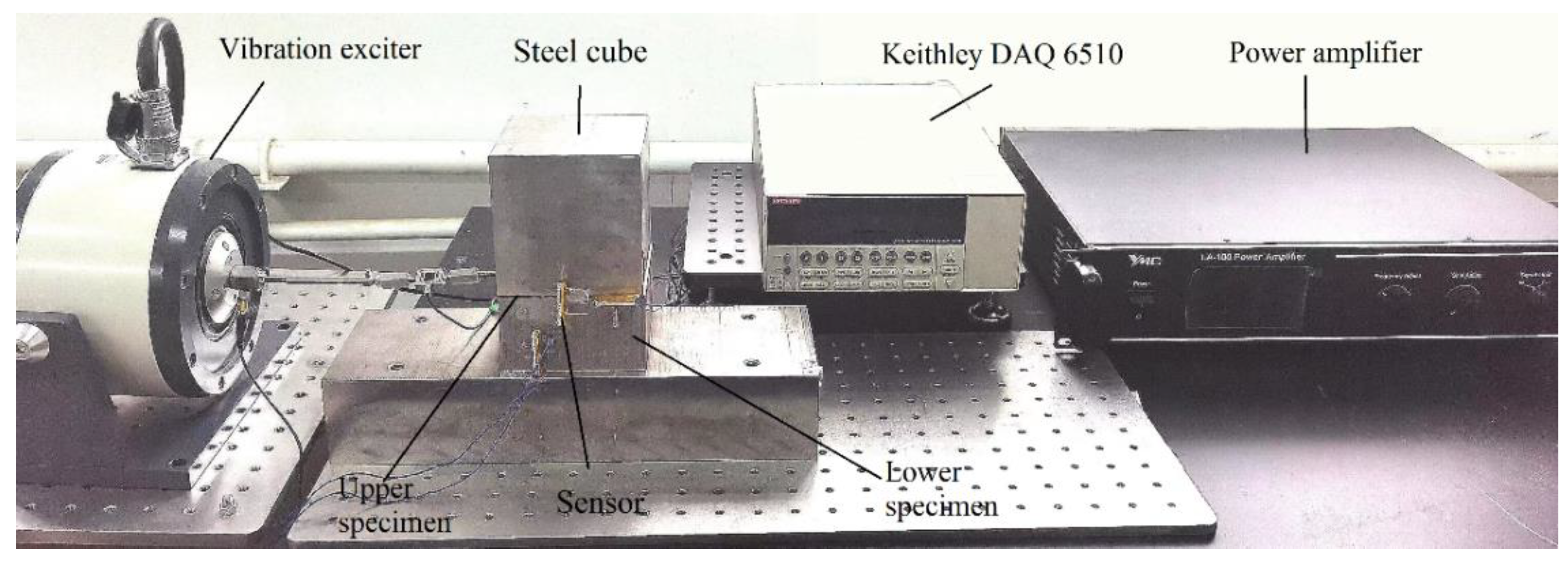
2.2. Test Bench
2.3. Signal Analysis and Test Instrument
3. Results
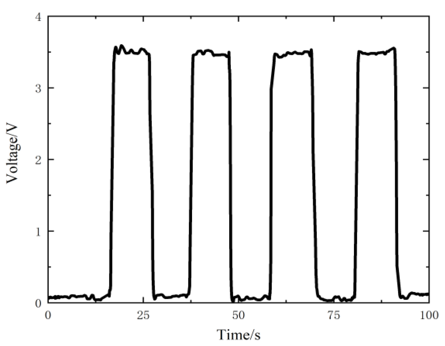
3.1. Calibration of the Sensor
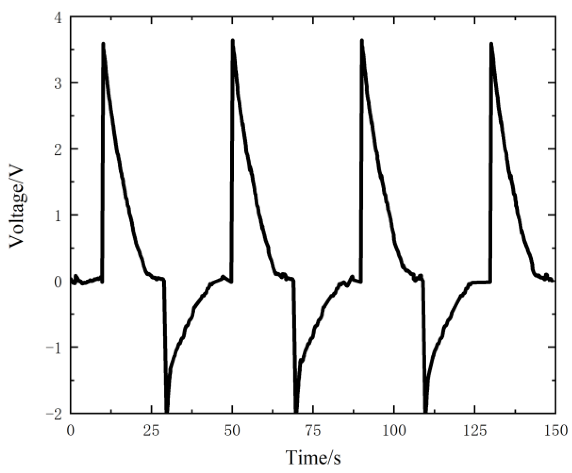
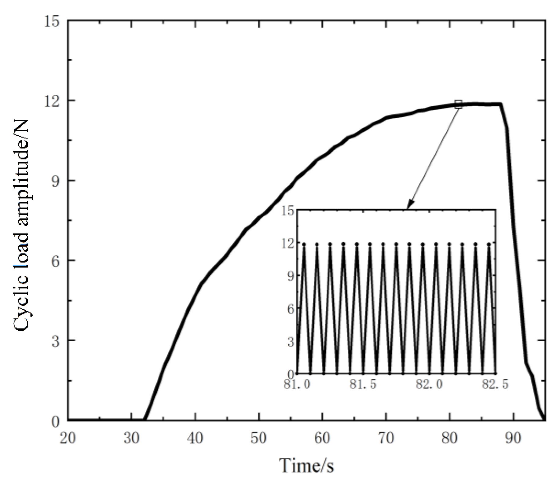
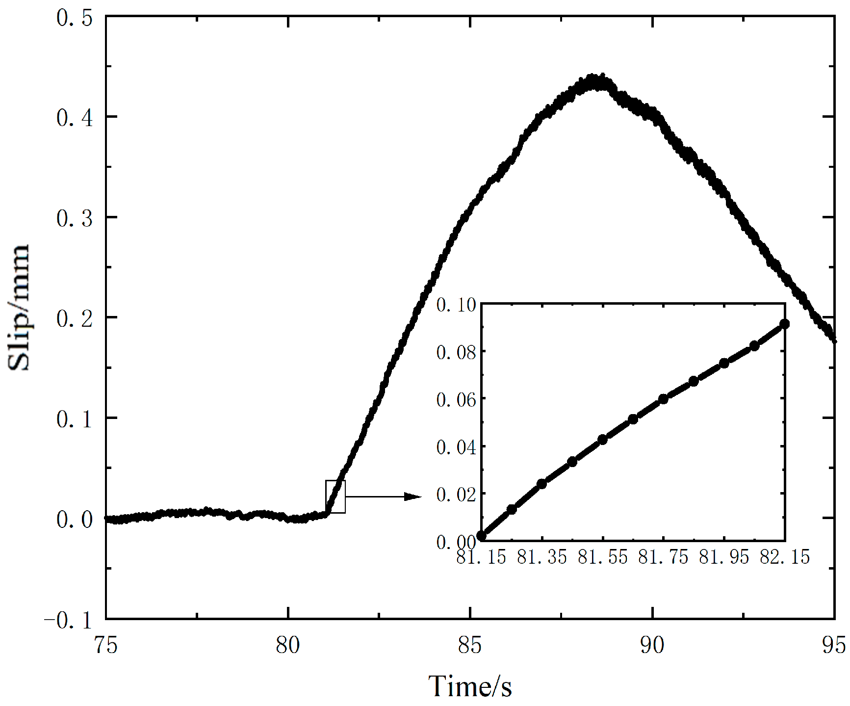
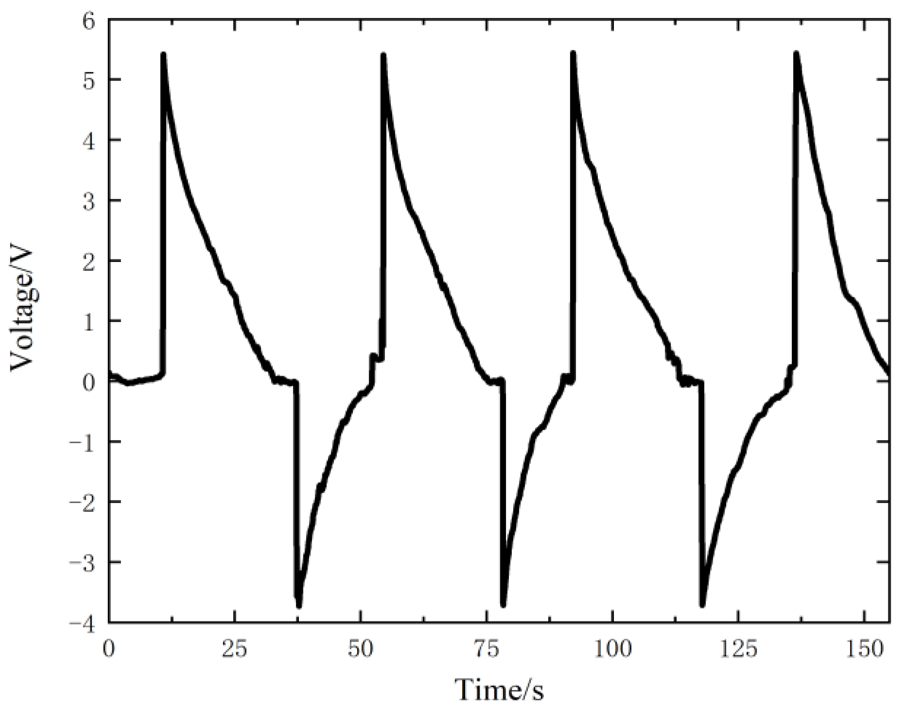
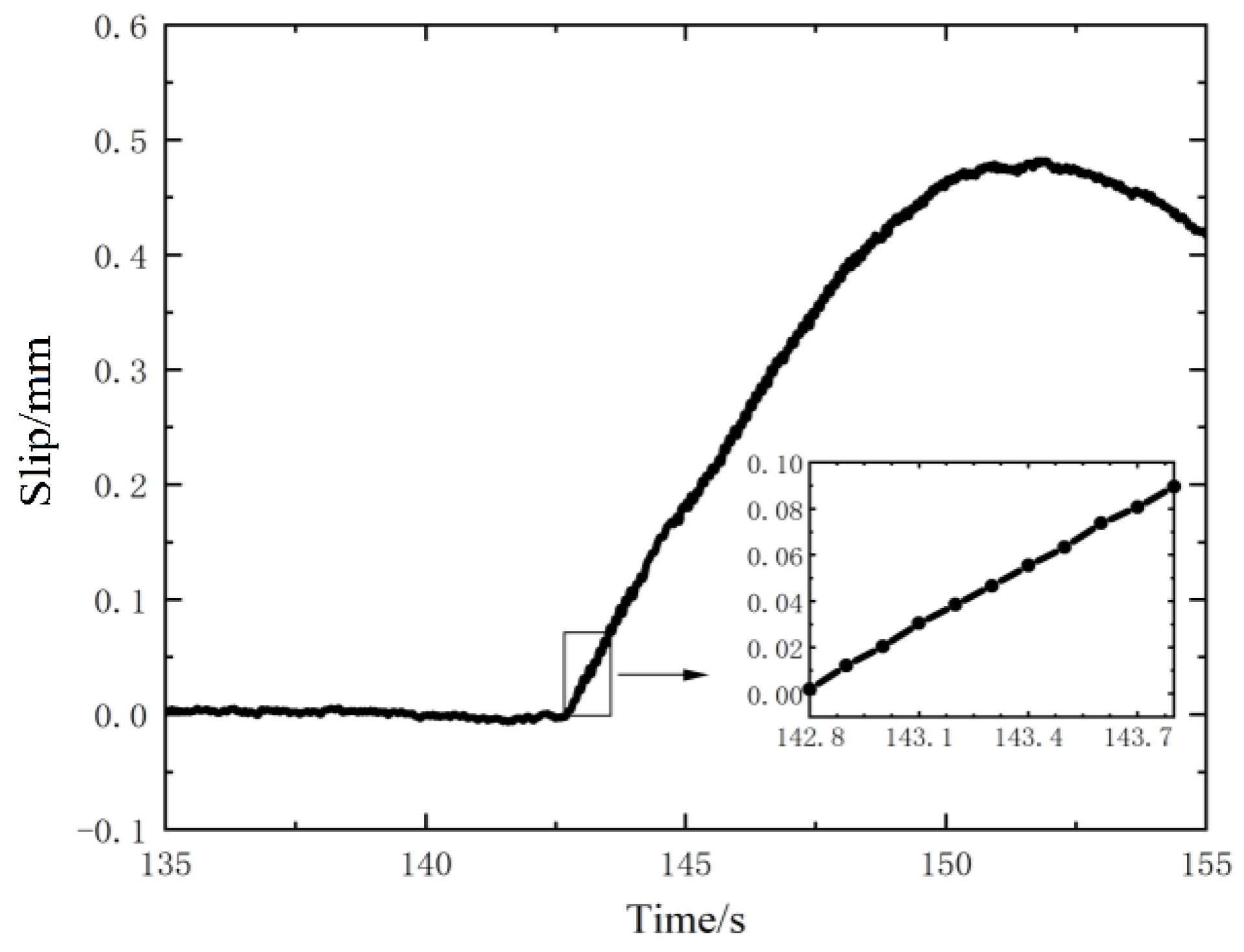
3.2. Dynamic Slip Test Results of Contact Surface under Cyclic Load
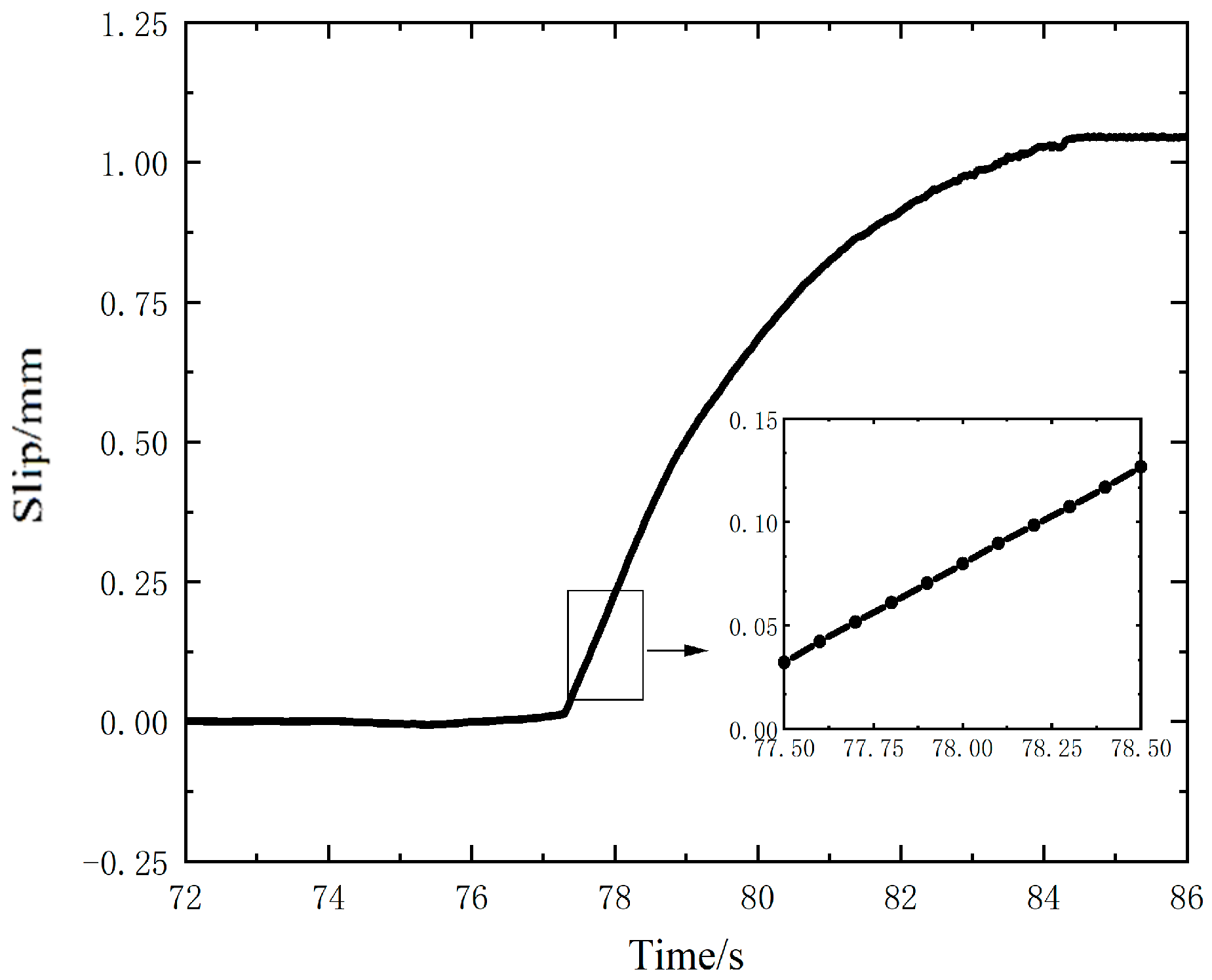
3.3. Verification of the Test Accuracy Using Keithley 6514 Electrometer
4. Performance Enhancement of Sensor by Thin Film
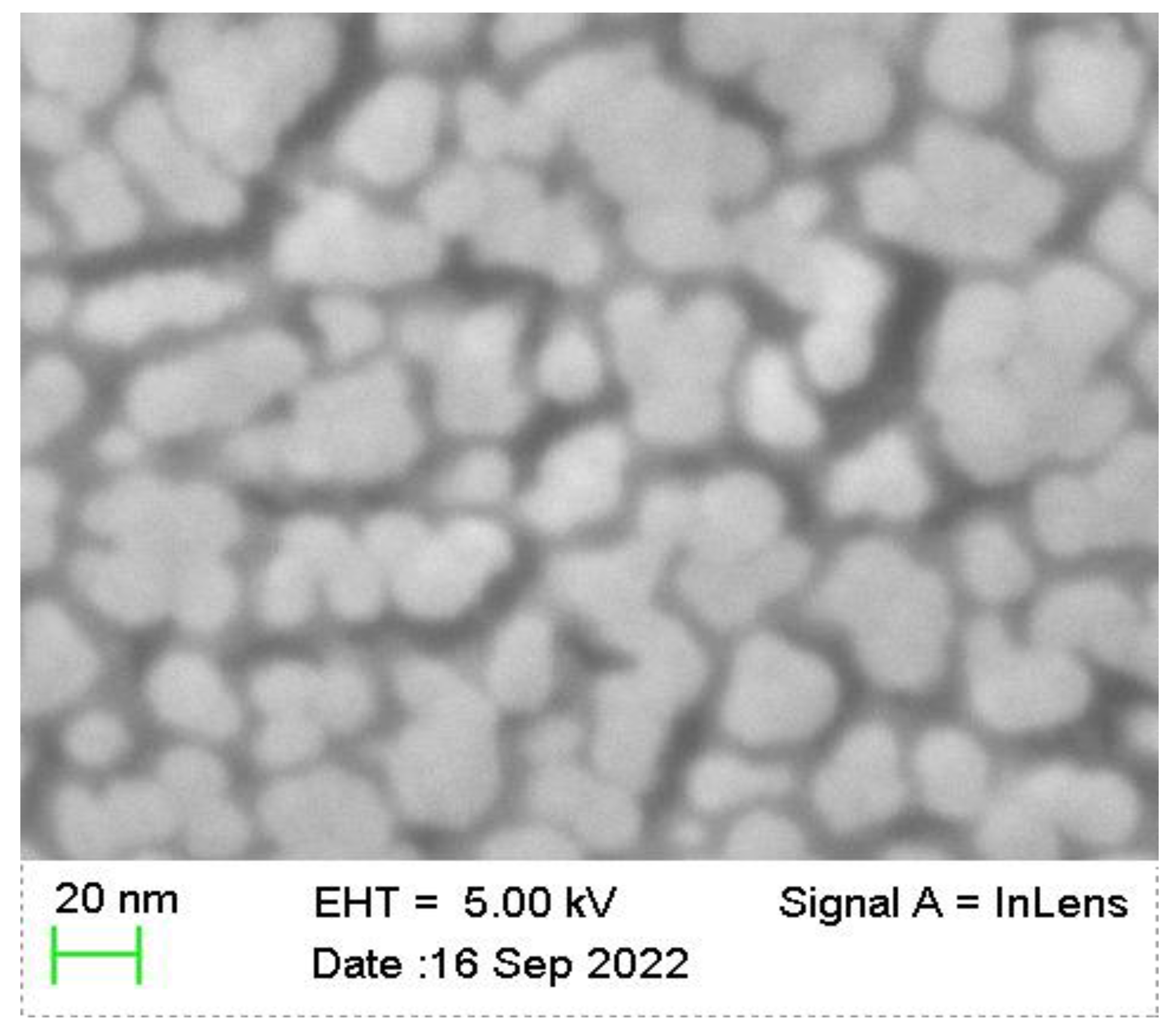
4.1. Role of Thin Film
4.2. Measurement Results Using the Self-Powered Sensor with Thin Film
5. Conclusions
Author Contributions
Funding
Institutional Review Board Statement
Informed Consent Statement
Data Availability Statement
Acknowledgments
Conflicts of Interest
References
- Antoni, N.; Nguyen, Q.-S.; Ligier, J.-L.; Saffré, P.; Pastor, J. On the cumulative microslip phenomenon. Eur. J. Mech. A-Solid 2007, 26, 626–646. [Google Scholar] [CrossRef]
- Gong, H.; Liu, J. Some factors affecting the loosening failure of bolted joints under vibration using finite element analysis. Proc. Inst. Mech. Eng. Part C: J. Mech. Eng. Sci. 2018, 232, 3942–3953. [Google Scholar] [CrossRef]
- Li, W.; Wang, H.; Feng, Z. Non-contact online thickness measurement system for metal films based on eddy current sensing with distance tracking technique. Rev. Sci. Instrum. 2016, 87, 045005. [Google Scholar] [CrossRef] [Green Version]
- Wang, X.; Gao, J.; Wang, L. Survey on the Laser Triangulation. Yiqi Yibiao Xuebao 2004, 25, 601–604+608. [Google Scholar]
- Warmuth, A.R.; Shipway, P.H.; Sun, W. Fretting wear mapping: The influence of contact geometry and frequency on debris formation and ejection for a steel-on-steel pair. Proc. R. Soc. A 2015, 471, 20140291. [Google Scholar] [CrossRef] [Green Version]
- Chen, M.; Li, X.; Lin, L.; Du, W.; Han, X.; Zhu, J.; Pan, C.; Wang, Z.L. Triboelectric nanogenerators as a self-powered motion tracking system. Adv. Funct. Mater. 2014, 24, 5059–5066. [Google Scholar] [CrossRef]
- Jing, Q.; Xie, Y.; Zhu, G.; Han, R.P.; Wang, Z.L. Self-powered thin-film motion vector sensor. Nat. Commun. 2015, 6, 8031. [Google Scholar] [CrossRef] [Green Version]
- Zhang, X.; Zheng, Y.; Wang, D.; Zhou, F. Solid-liquid triboelectrification in smart U-tube for multifunctional sensors. Nano Energy 2017, 40, 95–106. [Google Scholar] [CrossRef]
- Liu, H.; Wang, H.; Lyu, Y. A novel triboelectric nanogenerator based on carbon fiber reinforced composite lamina and as a self-powered displacement sensor. Nano Energy 2020, 224, 111231. [Google Scholar] [CrossRef]
- Wang, S.; Lin, L.; Wang, Z.L. Triboelectric nanogenerators as self-powered active sensors. Nano Energy 2015, 11, 436–462. [Google Scholar] [CrossRef] [Green Version]
- Zhou, Y.S.; Zhu, G.; Niu, S.; Liu, Y.; Bai, P.; Jing, Q.; Wang, Z.L. Nanometer resolution self-powered static and dynamic motion sensor based on micro-grated triboelectrification. Adv. Mater. 2014, 26, 1719–1724. [Google Scholar] [CrossRef] [PubMed]
- Li, C.; Wang, Z.; Shu, S.; Tang, W. A Self-Powered Vector Angle/Displacement Sensor Based on Triboelectric Nanogenerator. Micromachines 2021, 12, 231. [Google Scholar] [CrossRef]
- Yang, H.; Liu, W.; Xi, Y.; Lai, M.; Guo, H.; Liu, G.; Wang, M.; Li, T.; Ji, X.; Li, X. Rolling friction contact-separation mode hybrid triboelectric nanogenerator for mechanical energy harvesting and self-powered multifunctional sensors. Nano Energy 2018, 47, 539–546. [Google Scholar] [CrossRef]
- Wang, S.; Lin, L.; Wang, Z.L. Nanoscale triboelectric-effect-enabled energy conversion for sustainably powering portable electronics. Nano Lett. 2012, 12, 6339–6346. [Google Scholar] [CrossRef] [PubMed] [Green Version]
- Wang, S.; Lin, L.; Xie, Y.; Jing, Q.; Niu, S.; Wang, Z.L. Sliding-triboelectric nanogenerators based on in-plane charge-separation mechanism. Nano Lett. 2013, 13, 2226–2233. [Google Scholar] [CrossRef] [PubMed] [Green Version]
- Yang, Y.; Zhou, Y.S.; Zhang, H.; Liu, Y.; Lee, S.; Wang, Z.L. A single-electrode based triboelectric nanogenerator as self-powered tracking system. Adv. Mater. 2013, 25, 6594–6601. [Google Scholar] [CrossRef]
- Wang, S.; Xie, Y.; Niu, S.; Lin, L.; Wang, Z.L. Freestanding triboelectric-layer-based nanogenerators for harvesting energy from a moving object or human motion in contact and non-contact modes. Adv. Mater. 2014, 26, 2818–2824. [Google Scholar] [CrossRef]
- Zhu, G.; Pan, C.; Guo, W.; Chen, C.Y.; Zhou, Y.; Yu, R.; Wang, Z.L. Triboelectric-generator-driven pulse electrodeposition for micropatterning. Nano Lett. 2012, 12, 4960–4965. [Google Scholar] [CrossRef]
- Niu, S.; Wang, S.; Lin, L.; Liu, Y.; Zhou, Y.S.; Hu, F.; Wang, Z.L.; Wang, Z.L. Theoretical study of contact-mode triboelectric nanogenerators as an effective power source. Energy Environ. Sci. 2013, 6, 3576–3583. [Google Scholar] [CrossRef]
- Niu, S.; Liu, Y.; Wang, S.; Lin, L.; Zhou, Y.S.; Hu, Y.; Wang, Z.L. Theory of sliding-mode triboelectric nanogenerators. Adv. Mater. 2013, 25, 6184–6193. [Google Scholar] [CrossRef]
- Bai, P.; Zhu, G.; Jing, Q.; Wu, Y.; Yang, J.; Chen, J.; Ma, J.; Zhang, G.; Wang, Z.L. Transparent and flexible barcode based on sliding electrification for self-powered identification systems. Nano Energy 2015, 12, 278–286. [Google Scholar] [CrossRef]
- Chen, J.; Pu, X.; Guo, H.; Tang, Q.; Feng, L.; Wang, X.; Hu, C. A self-powered 2D barcode recognition system based on sliding mode triboelectric nanogenerator for personal identification. Nana Energy 2018, 43, 253–258. [Google Scholar] [CrossRef]
- Niu, S.; Wang, Z.L. Theoretical systems of triboelectric nanogenerators. Nano Energy 2015, 14, 161–192. [Google Scholar] [CrossRef] [Green Version]
- Wang, J.; Wu, C.; Dai, Y.; Zhao, Z.; Wang, A.; Zhang, T.; Wang, Z.L. Achieving ultrahigh triboelectric charge density for efficient energy harvesting. Nat. Commun. 2017, 8, 88. [Google Scholar] [CrossRef]


Publisher’s Note: MDPI stays neutral with regard to jurisdictional claims in published maps and institutional affiliations. |
© 2022 by the authors. Licensee MDPI, Basel, Switzerland. This article is an open access article distributed under the terms and conditions of the Creative Commons Attribution (CC BY) license (https://creativecommons.org/licenses/by/4.0/).
Share and Cite
Zhao, W.; Qin, W.; Ba, M.; Sun, Y. Measurement of Slips at Contact Interfaces Using a Self-Powered Sensor Based on Triboelectric Nanogenerators. Nanomaterials 2022, 12, 3510. https://doi.org/10.3390/nano12193510
Zhao W, Qin W, Ba M, Sun Y. Measurement of Slips at Contact Interfaces Using a Self-Powered Sensor Based on Triboelectric Nanogenerators. Nanomaterials. 2022; 12(19):3510. https://doi.org/10.3390/nano12193510
Chicago/Turabian StyleZhao, Wangjia, Wenjie Qin, Mingsen Ba, and Yu Sun. 2022. "Measurement of Slips at Contact Interfaces Using a Self-Powered Sensor Based on Triboelectric Nanogenerators" Nanomaterials 12, no. 19: 3510. https://doi.org/10.3390/nano12193510