
Efficient and Facile Synthetic Route of MoO3:MoS2 Hybrid Thin Layer via Oxidative Reaction of MoS2 Nanoflakes
 , , , ,
Abstract
:1. Introduction
2. Materials and Methods
2.1. Experimental Method
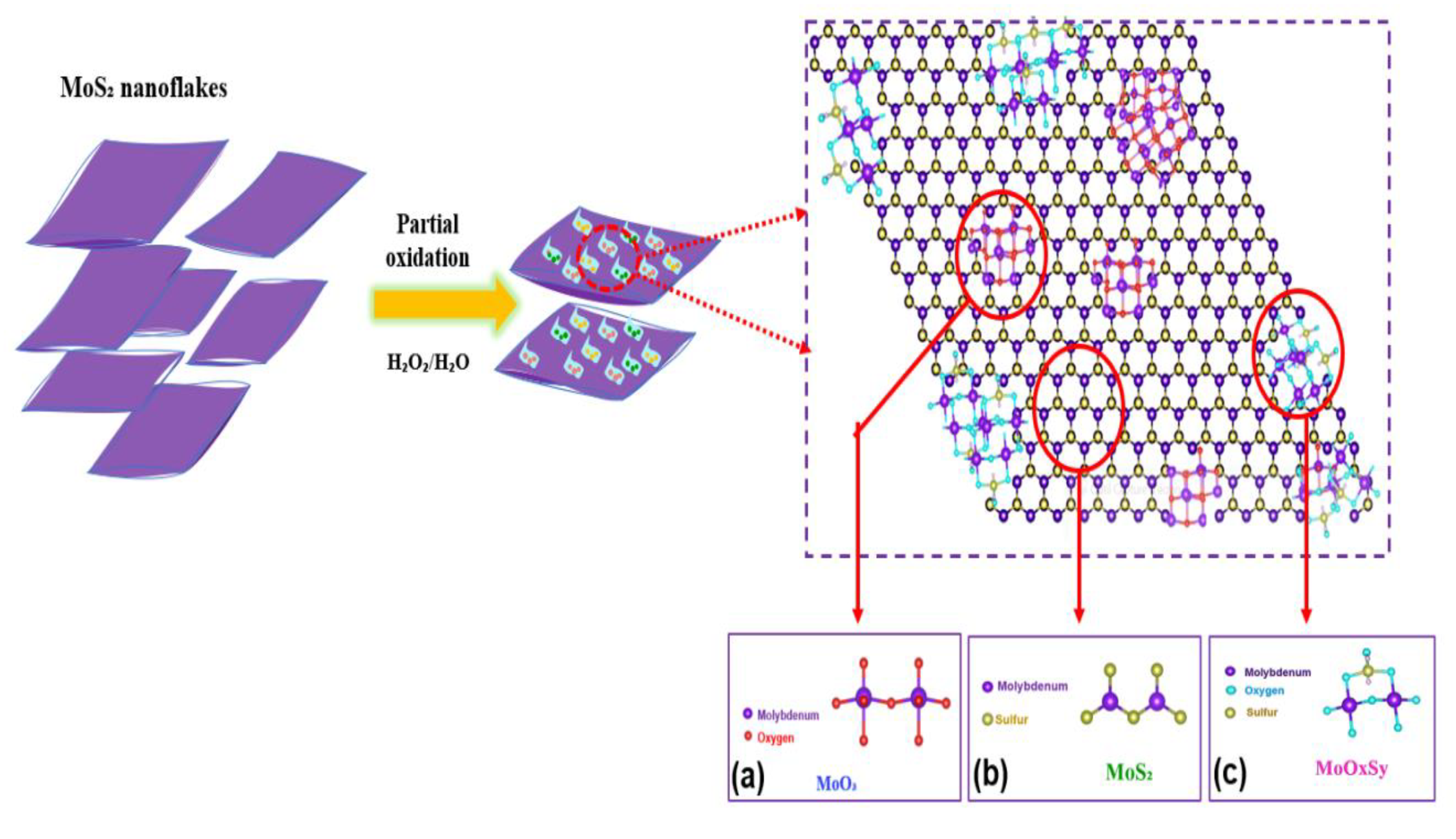
2.1.1. Partial Oxidation of Nanodispersed MoS2
2.1.2. Preparation of MoS2 and MoO3:MoS2 Hybrid Thin Films
3. Results

| Components | Binding Energies (eV) | References | |
|---|---|---|---|
| MoS2 | Mo 3d 5/2 | 229 | [23] |
| Mo 3d 3/2 | 233 | ||
| MoO3 | Mo 3d 5/2 | 233 | [27,28] |
| Mo 3d 3/2 | 236 | ||
| MoOxSy | Mo 3d 5/2 | 232 | [26] |
| Mo 3d 3/2 | 235 | ||
4. Conclusions
Author Contributions
Funding
Data Availability Statement
Acknowledgments
Conflicts of Interest
Appendix A
References
- Nakano, K.; Tajima, K. Organic Planar Heterojunctions: From Models for Interfaces in Bulk Heterojunctions to High-Performance Solar Cells. Adv. Mater. 2017, 29, 1603269. [Google Scholar] [CrossRef] [PubMed]
- Gupta, A.; Arunachalam, V.; Vasudevan, S. Liquid-Phase Exfoliation of MoS 2 Nanosheets: The Critical Role of Trace Water. J. Phys. Chem. Lett. 2016, 7, 4884–4890. [Google Scholar] [CrossRef] [PubMed]
- Singh, E.; Kim, K.S.; Yeom, G.Y.; Nalwa, H.S. Atomically Thin-Layered Molybdenum Disulfide (MoS2) for Bulk-Heterojunction Solar Cells. ACS Appl. Mater. Interfaces 2017, 9, 3223–3245. [Google Scholar] [CrossRef] [PubMed]
- Loiacono, A.; Gomez, M.J.; Negreiros, F.R.; Olmos-Asar, J.A.; Mariscal, M.M.; Lacconi, G.I.; Franceschini, E.A. MoS2 Effect on Nickel Electrochemical Activation: An Atomistic/Experimental Approach. J. Phys. Chem. C 2021, 125, 18640–18652. [Google Scholar] [CrossRef]
- Pesci, F.M.; Sokolikova, M.S.; Grotta, C.; Sherrell, P.C.; Reale, F.; Sharda, K.; Ni, N.; Palczynski, P.; Mattevi, C. MoS2/WS2 Heterojunction for Photoelectrochemical Water Oxidation. ACS Catal. 2017, 7, 4990–4998. [Google Scholar] [CrossRef]
- Duraisamy, S.; Ganguly, A.; Sharma, P.K.; Benson, J.; Davis, J.; Papakonstantinou, P. One-Step Hydrothermal Synthesis of Phase-Engineered MoS2/MoO3 Electrocatalysts for Hydrogen Evolution Reaction. ACS Appl. Nano Mater. 2021, 4, 2642–2656. [Google Scholar] [CrossRef]
- Yin, Z.; Zhang, X.; Cai, Y.; Chen, J.; Wong, J.I.; Tay, Y.-Y.; Chai, J.; Wu, J.; Zeng, Z.; Zheng, B.; et al. Preparation of MoS2-MoO3 Hybrid Nanomaterials for Light-Emitting Diodes. Angew. Chem. Int. Ed. 2014, 53, 12560–12565. [Google Scholar] [CrossRef]
- Martinez-Rojas, F.; Hssein, M.; El Jouad, Z.; Armijo, F.; Cattin, L.; Louarn, G.; Stephant, N.; del Valle, M.A.; Addou, M.; Soto, J.P.; et al. Mo(SxOy) thin films deposited by electrochemistry for application in organic photovoltaic cells. Mater. Chem. Phys. 2017, 201, 331–338. [Google Scholar] [CrossRef]
- Seynstahl, A.; Krauß, S.; Bitzek, E.; Meyer, B.; Merle, B.; Tremmel, S. Microstructure, Mechanical Properties and Tribological Behavior of Magnetron-Sputtered MoS2 Solid Lubricant Coatings Deposited under Industrial Conditions. Coatings 2021, 11, 455. [Google Scholar] [CrossRef]
- Lei, D.; Shang, W.; Zhang, X.; Li, Y.; Qiao, S.; Zhong, Y.; Deng, X.; Shi, X.; Zhang, Q.; Hao, C.; et al. Facile Synthesis of Heterostructured MoS2–MoO3 Nanosheets with Active Electrocatalytic Sites for High-Performance Lithium–Sulfur Batteries. ACS Nano 2021, 15, 20478–20488. [Google Scholar] [CrossRef]
- Zhang, Y.; Kuwahara, Y.; Mori, K.; Qian, X.; Zhao, Y.; Yamashita, H. Hybrid Phase MoS2 as a Noble Metal-Free Photocatalyst for Conversion of Nitroaromatics to Aminoaromatics. J. Phys. Chem. C 2021, 125, 20887–20895. [Google Scholar] [CrossRef]
- Kim, J.; Jung, M.; Lim, D.U.; Rhee, D.; Jung, S.H.; Cho, H.K.; Kim, H.-K.; Cho, J.H.; Kang, J. Area-Selective Chemical Doping on Solution-Processed MoS2 Thin-Film for Multi-Valued Logic Gates. Nano Lett. 2022, 22, 570–577. [Google Scholar] [CrossRef] [PubMed]
- Liu, C.; Wang, C.; Liao, C.; Golder, J.; Tsai, M.; Young, H.; Chen, C.; Wu, C.-I. Solution Processable Mixed-Solvent Exfoliated MoS 2 Nanosheets for Efficient and Robust Organic Light-Emitting Diodes. AIP Adv. 2018, 8, 045006. [Google Scholar] [CrossRef]
- Park, M.; Nguyen, T.P.; Choi, K.S.; Park, J.; Ozturk, A.; Kim, S.Y. MoS2-Nanosheet/Graphene-Oxide Composite Hole Injection Layer in Organic Light-Emitting Diodes. Electron. Mater. Lett. 2017, 13, 344–350. [Google Scholar] [CrossRef]
- Dasgupta, U.; Chatterjee, S.; Pal, A.J. Thin-Film Formation of 2D MoS2 and Its Application as a Hole-Transport Layer in Planar Perovskite Solar Cells. Sol. Energy Mater. Sol. Cells 2017, 172, 353–360. [Google Scholar] [CrossRef]
- Lin, Y.; Adilbekova, B.; Firdaus, Y.; Yengel, E.; Faber, H.; Sajjad, M.; Zheng, X.; Yarali, E.; Seitkhan, A.; Bakr, O.M.; et al. 17% Efficient Organic Solar Cells Based on Liquid Exfoliated WS2 as a Replacement for PEDOT:PSS. Adv. Mater. 2019, 31, 1902965. [Google Scholar] [CrossRef]
- Ma, H.; Shen, Z.; Ben, S. Understanding the exfoliation and dispersion of MoS2 nanosheets in pure water. J. Colloid Interface Sci. 2018, 517, 204–212. [Google Scholar] [CrossRef]
- Rakibuddin, M.; Shinde, M.A.; Kim, H. Facile sol–gel fabrication of MoS2 bulk, flake and quantum dot for electrochromic device and their enhanced performance with WO3. Electrochim. Acta 2020, 349, 136403. [Google Scholar] [CrossRef]
- Li, X.; Zhang, W.; Wu, Y.; Min, C.; Fang, J. Solution-Processed MoSx as an Efficient Anode Buffer Layer in Organic Solar Cells. ACS Appl. Mater. Interfaces 2013, 5, 8823–8827. [Google Scholar] [CrossRef]
- Tsigkourakos, M.; Kainourgiaki, M.; Skotadis, E.; Giannakopoulos, K.P.; Tsoukalas, D.; Raptis, Y.S. Capping technique for chemical vapor deposition of large and uniform MoS2 flakes. Thin Solid Film. 2021, 733, 138808. [Google Scholar] [CrossRef]
- Hu, L.; Ren, Y.; Yang, H.; Xu, Q. Fabrication of 3D Hierarchical MoS2/Polyaniline and MoS2/C Architectures for Lithium-Ion Battery Applications. ACS Appl. Mater. Interfaces 2014, 6, 14644–14652. [Google Scholar] [CrossRef] [PubMed]
- Ramasamy, M.S.; Ryu, K.Y.; Lim, J.W.; Bibi, A.; Kwon, H.; Lee, J.; Kim, D.H.; Kim, K. Solution-Processed PEDOT:PSS/MoS2 Nanocomposites as Efficient Hole-Transporting Layers for Organic Solar Cells. Nanomaterials 2019, 9, 1328. [Google Scholar] [CrossRef] [PubMed]
- Yun, J.; Noh, Y.; Lee, C.-H.; Na, S.; Lee, S.; Jo, S.M.; Joh, H.; Kim, D. Exfoliated and Partially Oxidized MoS2 Nanosheets by One-Pot Reaction for Efficient and Stable Organic Solar Cells. Small 2014, 10, 2319–2324. [Google Scholar] [CrossRef]
- Ftouhi, H.; Lamkaouane, H.; Louarn, G.; Diani, M.; Bernède, J.C.; Addou, M.; Cattin, L. Low temperature synthesis of MoS2 and MoO3: MoS2 hybrid thin films via the use of an original hybrid sulfidation technique. Surf. Interfaces 2022, 32, 102120. [Google Scholar] [CrossRef]
- Kim, Y.; Yassitepe, E.; Voznyy, O.; Comin, R.; Walters, G.; Gong, X.; Kanjanaboos, P.; Nogueira, A.F.; Sargent, E.H. Efficient Luminescence from Perovskite Quantum Dot Solids. ACS Appl. Mater. Interfaces 2015, 7, 25007–25013. [Google Scholar] [CrossRef]
- Song, S.H.; Kim, B.H.; Choe, D.-H.; Kim, J.; Kim, D.C.; Lee, D.J.; Kim, J.M.; Chang, K.J.; Jeon, S. Bandgap Widening of Phase Quilted, 2D MoS2 by Oxidative Intercalation. Adv. Mater. 2015, 27, 3152–3158. [Google Scholar] [CrossRef]
- Bortoti, A.A.; de Freitas Gavanski, A.; Velazquez, Y.R..; Galli, A.; de Castro, E.G. Facile and low cost oxidative conversion of MoS2 in α-MoO3: Synthesis, characterization and application. J. Solid State Chem. 2017, 252, 111–118. [Google Scholar] [CrossRef]
- Hwang, M.-J.; Han, S.W.; Nguyen, T.-B.; Hong, S.C.; Ryu, K.-S. Preparation of MoO3/MoS2/TiO2 Composites for Catalytic Degradation of Methylene Blue. J. Nanosci. Nanotechnol. 2012, 12, 5884–5891. [Google Scholar] [CrossRef]
- Kejzlar, P.; Švec, M.; Macajová, E. The Usage of Backscattered Electrons in Scanning Electron Microscopy. Manuf. Technol. 2014, 14, 333–336. [Google Scholar] [CrossRef]
- Dong, L.; Lin, S.; Yang, L.; Zhang, J.; Yang, C.; Yang, D.; Lu, H. Spontaneous exfoliation and tailoring of MoS2 in mixed solvents. Chem. Commun. 2014, 50, 15936–15939. [Google Scholar] [CrossRef]
- Kim, J.; Kwon, S.; Cho, D.-H.; Kang, B.; Kwon, H.; Kim, Y.; Park, S.O.; Jung, G.Y.; Shin, E.; Kim, W.-G.; et al. Direct Exfoliation and Dispersion of Two-Dimensional Materials in Pure Water via Temperature Control. Nat. Commun. 2015, 6, 8294. [Google Scholar] [CrossRef] [PubMed]
- Rodriguez, C.L.C.; Muñoz, P.A.R.; Donato, K.Z.; Seixas, L.; Donato, R.K.; Fechine, G.J.M. Understanding the Unorthodox Stabilization of Liquid Phase Exfoliated Molybdenum Disulfide (MoS2) in Water Medium. Phys. Chem. Chem. Phys. 2020, 22, 1457–1465. [Google Scholar] [CrossRef] [PubMed]
- Walia, S.; Balendhran, S.; Wang, Y.; Ab Kadir, R.; Sabirin Zoolfakar, A.; Atkin, P.; Zhen Ou, J.; Sriram, S.; Kalantar-zadeh, K.; Bhaskaran, M. Characterization of metal contacts for two-dimensional MoS2 nanoflakes. Appl. Phys. Lett. 2013, 103, 232105. [Google Scholar] [CrossRef]
- Yang, X.; Fu, W.; Liu, W.; Hong, J.; Cai, Y.; Jin, C.; Xu, M.; Wang, H.; Yang, D.; Chen, H. Engineering crystalline structures of two-dimensional MoS2 sheets for high-performance organic solar cells. J. Mater. Chem. A 2014, 2, 7727–7733. [Google Scholar] [CrossRef]
- Wang, J.; Huang, C.; You, Y.; Guo, Q.; Xue, G.; Hong, H.; Jiao, Q.; Yu, D.; Du, L.; Zhao, Y.; et al. Monitoring the Material Quality of Two-Dimensional Transition Metal Dichalcogenides. J. Phys. Chem. C 2022, 126, 3797–3810. [Google Scholar] [CrossRef]
- Mandal, D.; Routh, P.; Nandi, A.K. Quantum-Dot-Mediated Controlled Synthesis of Dual Oxides of Molybdenum from MoS2: Quantification of Supercapacitor Efficacy. Chem. Asian J. 2018, 13, 3871–3884. [Google Scholar] [CrossRef]
- Iqbal, N.; Khan, I.; Ali, A.; Qurashi, A. A sustainable molybdenum oxysulphide-cobalt phosphate photocatalyst for effectual solar-driven water splitting. J. Adv. Res. 2022, 36, 15–26. [Google Scholar] [CrossRef]
- Shin, S.; Jin, Z.; Ham, S.-Y.; Lee, S.; Shin, D.-S.; Min, Y.-S. Effect of oxygen incorporation in amorphous molybdenum sulfide on electrochemical hydrogen evolution. Appl. Surf. Sci. 2019, 487, 981–989. [Google Scholar] [CrossRef]
- Afanasiev, P.; Lorentz, C. Oxidation of Nanodispersed MoS2 in Ambient Air: The Products and the Mechanistic Steps. J. Phys. Chem. C 2019, 123, 7486–7494. [Google Scholar] [CrossRef]
- Muscuso, L.; Cravanzola, S.; Cesano, F.; Scarano, D.; Zecchina, A. Optical, Vibrational, and Structural Properties of MoS2 Nanoparticles Obtained by Exfoliation and Fragmentation via Ultrasound Cavitation in Isopropyl Alcohol. J. Phys. Chem. C 2015, 119, 3791–3801. [Google Scholar] [CrossRef]
- Shi, Y.; Li, H.; Wong, J.I.; Zhang, X.; Wang, Y.; Song, H.; Yang, H.Y. MoS2 Surface Structure Tailoring via Carbonaceous Promoter. Sci. Rep. 2015, 5, 10378. [Google Scholar] [CrossRef] [PubMed]
- Stadelmann, P. JEMS Electron Microscopy Simulation Software (Version V4) [Software]. 2019. Available online: www.jems-swiss.ch (accessed on 7 September 2022).
- Coleman, J.N.; Lotya, M.; O’Neill, A.; Bergin, S.D.; King, P.J.; Khan, U.; Young, K.; Gaucher, A.; De, S.; Smith, R.J.; et al. Two-Dimensional Nanosheets Produced by Liquid Exfoliation of Layered Materials. Science 2011, 331, 568–571. [Google Scholar] [CrossRef] [PubMed]
- Fernandes Cauduro, A.L.; Fabrim, Z.E.; Ahmadpour, M.; Fichtner, P.F.P.; Hassing, S.; Rubahn, H.-G.; Madsen, M. Tuning the optoelectronic properties of amorphous MoOx films by reactive sputtering. Appl. Phys. Lett. 2015, 106, 202101. [Google Scholar] [CrossRef] [Green Version]


| Experimental Conditions | MoS2 (at%) | MoO3 (at%) | MoOxSy (at%) |
|---|---|---|---|
| To light | 17 | 71 | 12 |
| To darkness | 30 | 60 | 10 |
| Sample | MoS2 (at%) | MoO3 (at%) | MoOxSy (at%) |
|---|---|---|---|
| N°1 | 18 | 62 | 20 |
| N°2 | 17 | 56 | 27 |
| N°3 | 16 | 66 | 17 |
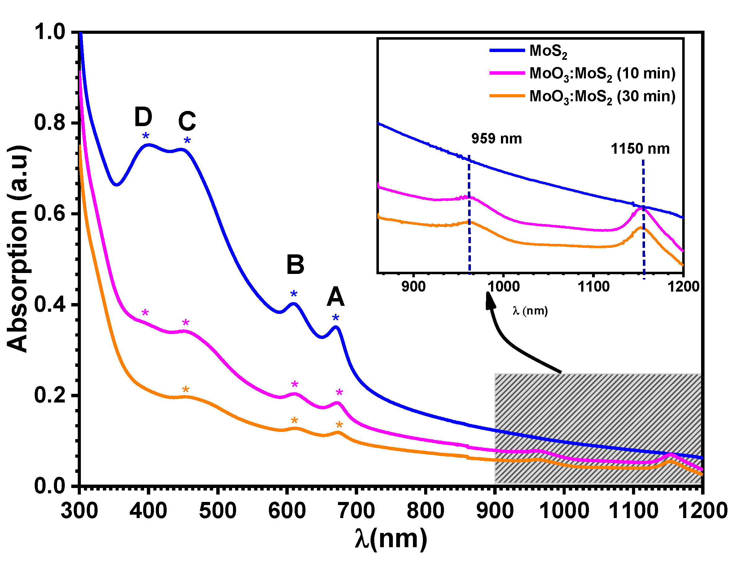
| Excitonic Transition | Exfoliated MoS2 | Hybrid MoO3:MoS2 | |
|---|---|---|---|
| 10 min | 30 min | ||
| A | 670 | 673 | 673 |
| B | 607 | 610 | 610 |
| C | 448 | 454 | 454 |
| D | 398 | 398 | ----- |
| Reaction Duration (min) | MoS2 (at%) | MoO3 (at%) | MoOxSy (at%) |
|---|---|---|---|
| 5 | 25 | 56 | 19 |
| 10 | 17 | 60 | 23 |
| 15 | 5 | 52 | 43 |
| 30 | 4 | 66 | 30 |
| 45 | 2.5 | 75 | 23 |
Publisher’s Note: MDPI stays neutral with regard to jurisdictional claims in published maps and institutional affiliations. |
© 2022 by the authors. Licensee MDPI, Basel, Switzerland. This article is an open access article distributed under the terms and conditions of the Creative Commons Attribution (CC BY) license (https://creativecommons.org/licenses/by/4.0/).
Share and Cite
Lamkaouane, H.; Ftouhi, H.; Richard-Plouet, M.; Gautier, N.; Stephant, N.; Zazoui, M.; Addou, M.; Cattin, L.; Bernède, J.C.; Mir, Y.; et al. Efficient and Facile Synthetic Route of MoO3:MoS2 Hybrid Thin Layer via Oxidative Reaction of MoS2 Nanoflakes. Nanomaterials 2022, 12, 3171. https://doi.org/10.3390/nano12183171
Lamkaouane H, Ftouhi H, Richard-Plouet M, Gautier N, Stephant N, Zazoui M, Addou M, Cattin L, Bernède JC, Mir Y, et al. Efficient and Facile Synthetic Route of MoO3:MoS2 Hybrid Thin Layer via Oxidative Reaction of MoS2 Nanoflakes. Nanomaterials. 2022; 12(18):3171. https://doi.org/10.3390/nano12183171
Chicago/Turabian StyleLamkaouane, Hind, Hajar Ftouhi, Mireille Richard-Plouet, Nicolas Gautier, Nicolas Stephant, Mimoun Zazoui, Mohammed Addou, Linda Cattin, Jean Christian Bernède, Yamina Mir, and et al. 2022. "Efficient and Facile Synthetic Route of MoO3:MoS2 Hybrid Thin Layer via Oxidative Reaction of MoS2 Nanoflakes" Nanomaterials 12, no. 18: 3171. https://doi.org/10.3390/nano12183171