Effects of SiC and Resorcinol–Formaldehyde (RF) Carbon Coatings on Silicon-Flake-Based Anode of Lithium Ion Battery


Abstract
:1. Introduction
1.1. High-Capacity Long-Cycling-Life Anode for Lithium Ion Battery
1.2. Silicon-Based Anode
1.3. Carbon Coatings
1.4. Silicon Oxide for Silicon-Based Anode
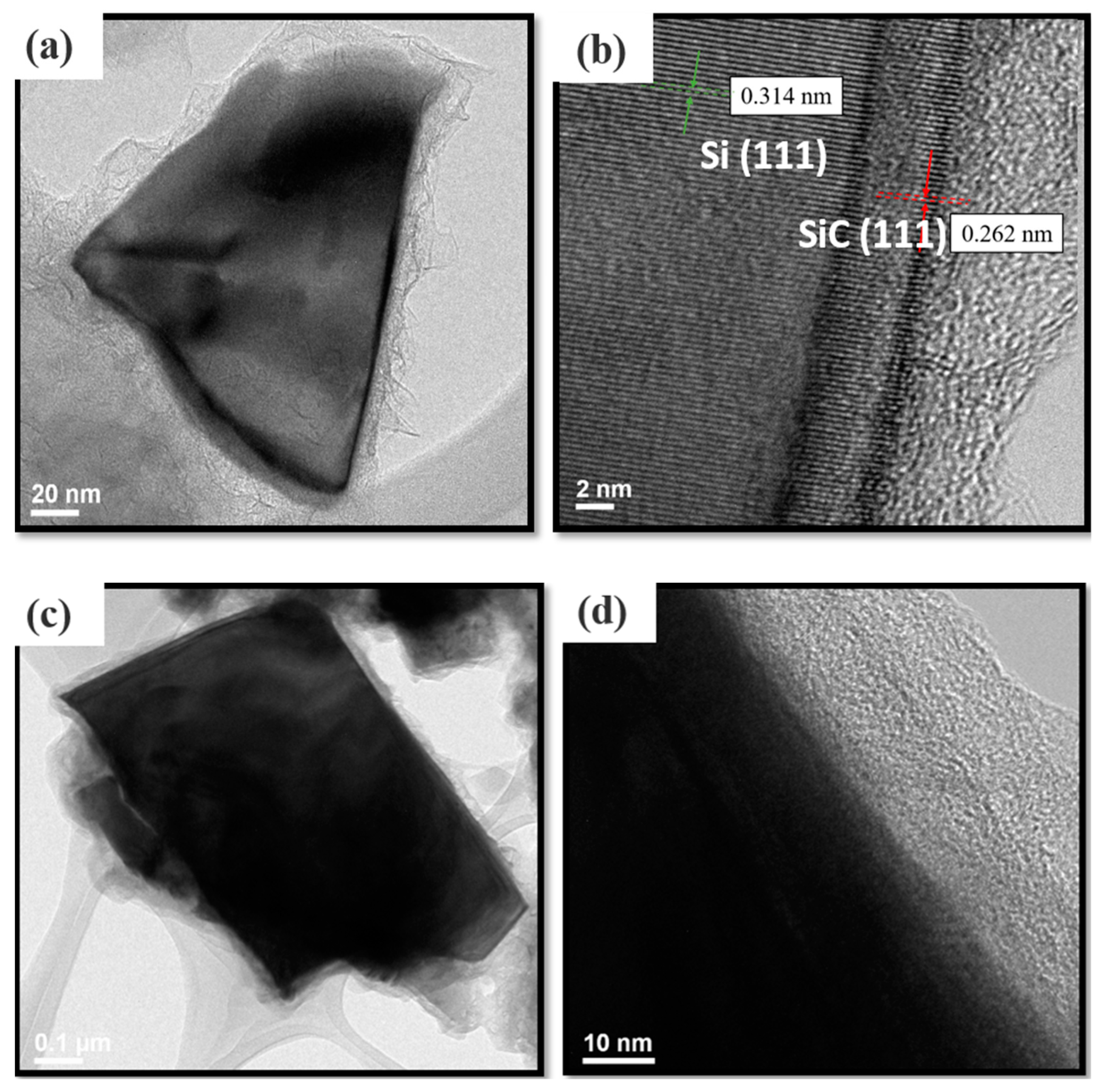
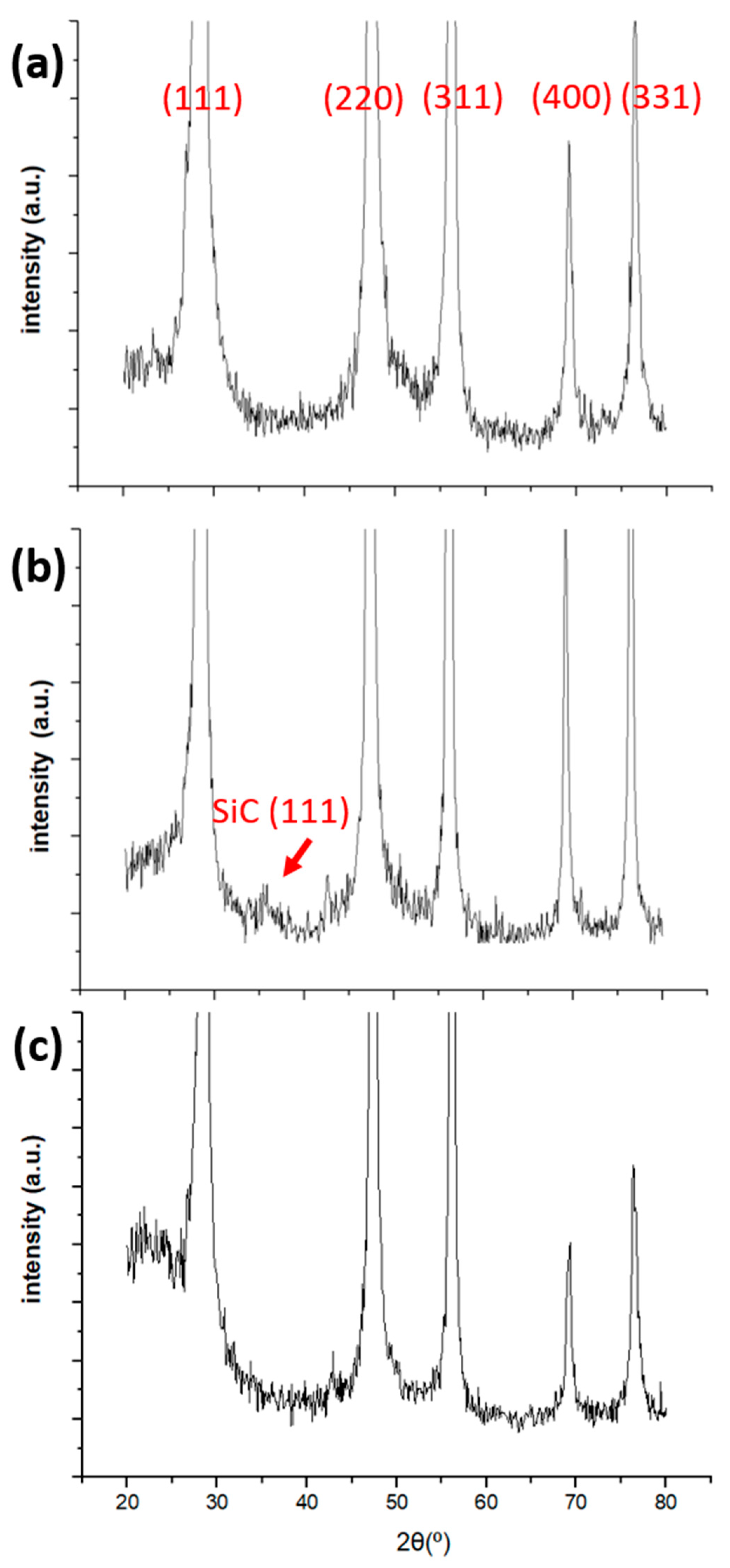
1.5. Silicon Carbide for Silicon-Based Anode
2. Materials and Methods
2.1. Chemicals
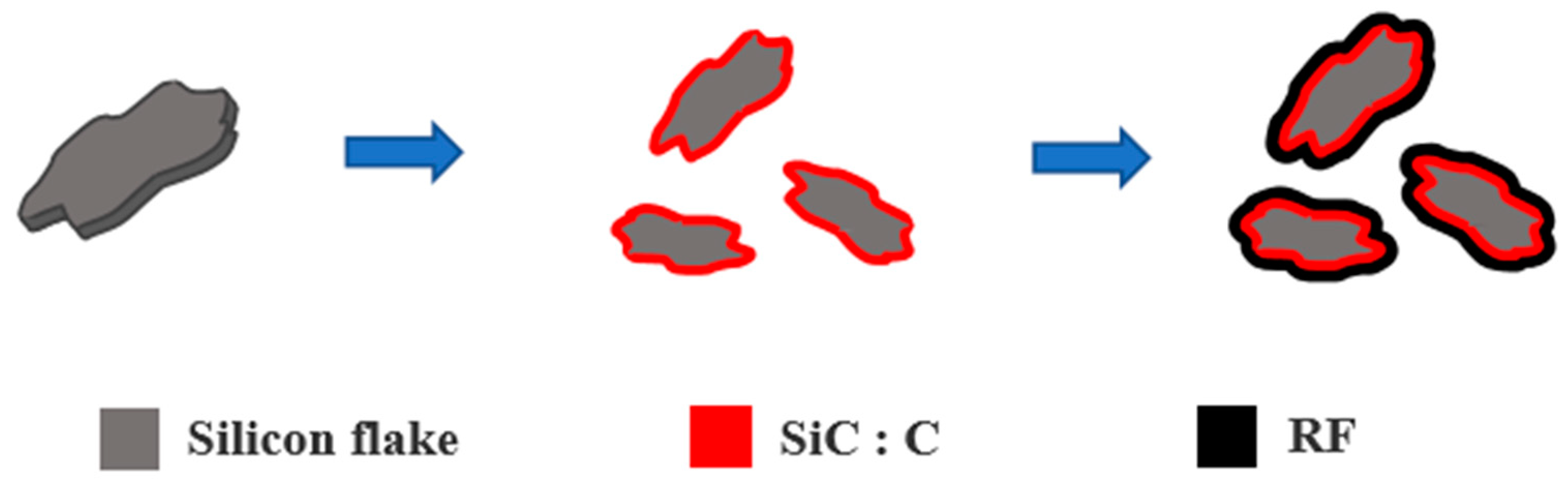
2.2. Synthesis of SiC
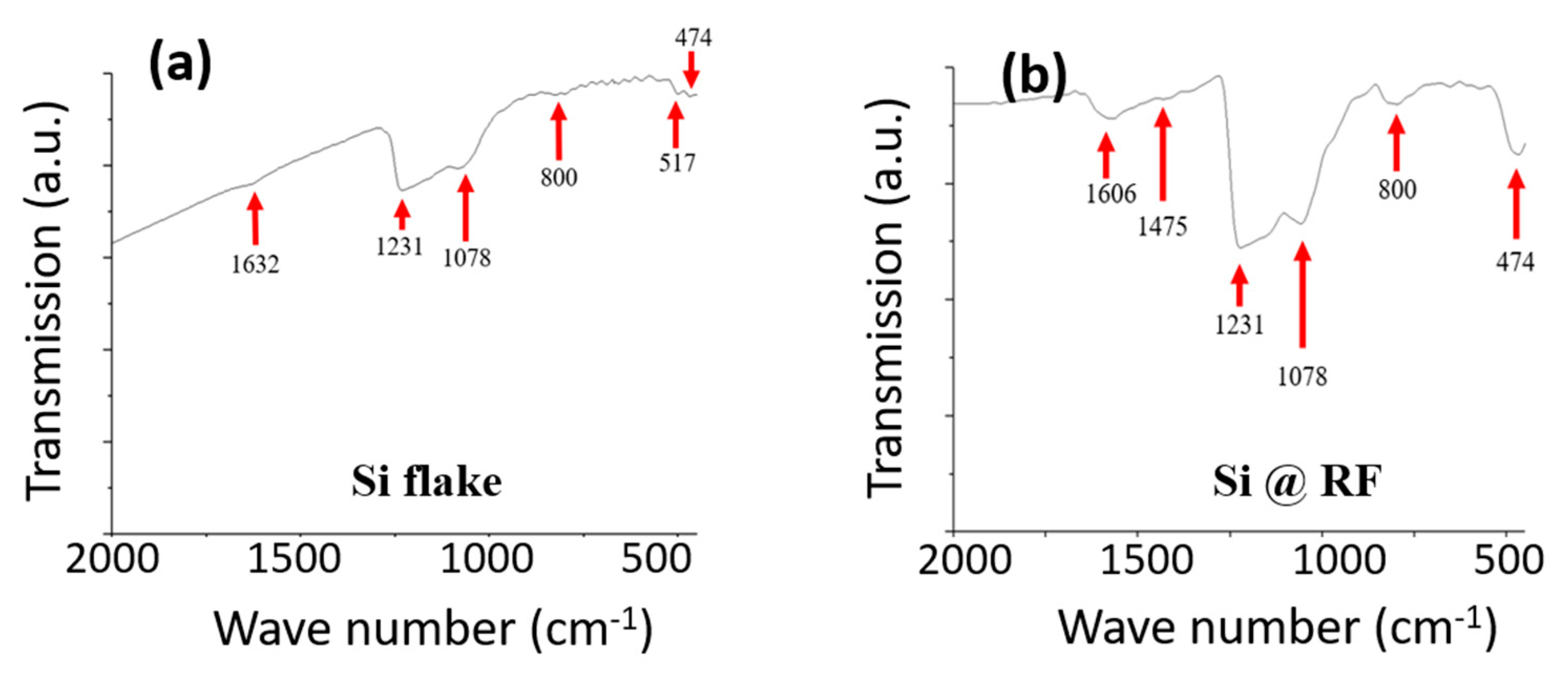
2.3. Deposition of RF Carbon Coatings
2.4. Materials Characterization
2.5. Resistance Measurements
2.6. Test Cells
2.7. Characterization of Test Cells
3. Results and Discussion
4. Conclusions
Author Contributions
Funding
Institutional Review Board Statement
Informed Consent Statement
Conflicts of Interest
References
- Chiang, Y.-M. Building a Better Battery. Science 2010, 330, 1485–1486. [Google Scholar]
- Armand, M.; Tarascon, J.-M. Building better batteries. Nature 2008, 451, 652–657. [Google Scholar]
- Bruce, P.G.; Freunberger, S.A.; Hardwick, L.J.; Tarascon, J.-M. Li-O2 and Li-S batteries with high energy storage. Nat. Mater. 2011, 11, 19–229. [Google Scholar]
- Amine, K.; Kanno, R.; Tzeng, Y. Rechargeable Lithium Batteries and Beyond: Progress, Challenges, and Future Directions. MRS Bull. 2014, 39, 395–401. [Google Scholar]
- Xie, J.; Lu, Y.-C. A retrospective on lithium-ion batteries. Nat. Commun. 2020, 11, 2499. [Google Scholar]
- Whittingham, M.S. Lithium Batteries and Cathode Materials. Chem. Rev. 2004, 104, 4271–4302. [Google Scholar]
- Kovalenko, I.; Zdyrko, B.; Magasinski, A.; Hertzberg, B.; Milicev, Z. A major constituent of brown algae for use in high-capacity Li-ion batteries. Science 2011, 334, 75–79. [Google Scholar]
- Chan, C.K.; Peng, H.; Liu, G.; McIlwrath, K.; Zhang, X.F. High-performance lithium battery anodes using silicon nanowires. Nat. Nanotechnol. 2008, 3, 31–35. [Google Scholar]
- Magasinski, A.; Dixon, P.; Hertzberg, B.; Kvit, A. High-performance lithium-ion anodes using a hierarchical bottom-up approach. Nat. Mater. 2010, 9, 353–358. [Google Scholar]
- Dahn, J.R.; Zheng, T.; Liu, Y.; Xue, J.S. Mechanisms for Lithium Insertion in Carbonaceous Materials. Science 1995, 270, 590–593. [Google Scholar]
- Terranova, M.L.; Orlanducci, S.; Tamburri, E.; Guglielmotti, V.; Rossi, M. Si/C hybrid nanostructures for Li-ion anodes: An overview. J. Power Sources 2014, 246, 167–177. [Google Scholar]
- Wang, B.; Li, X.; Qiu, T.; Luo, B.; Ning, J.; Li, J.; Zhang, X.; Liang, M.; Zhi, L. High Volumetric Capacity Silicon-Based Lithium Battery Anodes by Nanoscale System Engineering. Nano Lett. 2013, 13, 5578–5584. [Google Scholar]
- Ge, M.; Fang, X.; Rong, J.; Zhou, C. Review of porous silicon preparation and its application for lithium-ion battery anodes. Nanotechnology 2013, 24, 422001. [Google Scholar]
- Cho, J.-H.; Picraux, S.T. Enhanced lithium ion battery cycling of silicon nanowire anodes by template growth to eliminate silicon underlayer islands. Nano Lett. 2013, 13, 5740. [Google Scholar]
- Tzeng, Y.; Chen, C.-A. Composite Electrode Material and Method for Manufacturing the Same. U.S. Patent #10,411,253, 10 September 2019. [Google Scholar]
- Pan, Y.-T.; Tzeng, Y. Silicon Nanoparticles in Graphene Sponge for Long-Cycling-Life and High-Capacity Anode of Lithium Ion Battery. IEEE Trans. Nanotechnol. 2019, 18, 1097–1102. [Google Scholar]
- Ge, M.; Rong, J.; Fang, X.; Zhou, C. Porous Doped Silicon Nanowires for Lithium Ion Battery Anode with Long Cycle Life. Nano Lett. 2012, 12, 2318–2323. [Google Scholar]
- Jeong, Y.K.; Huang, W.; Vilá, R.A.; Huang, W.; Wang, J.; Kim, S.C.; Kim, Y.S.; Zhao, J.; Cui, Y. Microclusters of Kinked Silicon Nanowires Synthesized by a Recyclable Iodide Process for High-Performance Lithium-Ion Battery Anodes. Adv. Energy Mater. 2020, 10, 2002108. [Google Scholar]
- Liu, X.H.; Zhong, L.; Huang, S.; Mao, S.X.; Zhu, T.; Yu, J.; Liu, H. Size-Dependent Fracture of Silicon Nanoparticles During Lithiation. ACS Nano 2012, 6, 1522–1531. [Google Scholar]
- Qi, W.; Shapter, J.G.; Wu, Q.; Yin, T.; Gao, G.; Cui, D. Nanostructured anode materials for lithium-ion batteries: Principle, recent progress and future perspectives. J. Mater. Chem. A 2017, 5, 19521. [Google Scholar]
- Roselin, L.S.; Juang, R.-S.; Hsieh, C.-T.; Sagadevan, S.; Umar, A.; Selvin, R.; Hegazy, H.H. Recent Advances and Perspectives of Carbon-Based Nanostructures as Anode Materials for Li-ion Batteries. Materials 2019, 12, 1229. [Google Scholar]
- Wong, D.P.; Tseng, H.-P.; Chen, Y.-T.; Hwang, B.-J.; Chen, L.-C.; Chen, K.-H. A stable silicon/graphene composite using solvent exchange method as anode materialfor lithium ion batteries. Carbon 2013, 63, 397–403. [Google Scholar]
- Xu, B.; Lin, C.X.; Wang, B.; Zhang, Z.; Zhao, X.S. Stablilization of silicon nanoparticles in graphene aerogel framework for lithium ion storage. RSC Adv. 2015, 5, 30624. [Google Scholar]
- Ikonen, T.; Kalidas, N.; Lahtinen, K.; Isoniemi, T.; Toppari, J.J.; Vazquez, E.; Herrero-Chamorro, M.A.M.; Fierro, J.L.G.; Kallio, T.; Lehto, V.-P. Conjugation with carbon nanotubes improves the performance of mesoporous silicon as Li-ion battery anode. Sci. Rep. 2020, 10, 5589. [Google Scholar]
- Li, X.; Zhang, G.; Zhang, L.; Zhong, M.; Yuan, X. Silicon/Graphite/Carbon Nanotubes Composites as Anode for Lithium Ion Battery. Int. J. Electrochem. Sci. 2015, 10, 2801–2811. [Google Scholar]
- Ng, S.H.; Wang, J.; Wexler, D.; Chew, S.Y.; Liu, H.K. Amorphous Carbon-Coated Silicon Nanocomposites: A Low-Temperature Synthesis via Spray Pyrolysis and Their Application as High-Capacity Anodes for Lithium Ion Batteries. J. Phys. Chem. C 2007, 111, 11131–11138. [Google Scholar]
- Wu, J.; Cao, Y.; Zhao, H.; Mao, J.; Guo, Z. The critical role of carbon in marrying silicon and graphite anodes for high-energy lithium-ion batteries. Carbon Energy 2019, 1, 57–76. [Google Scholar] [CrossRef] [Green Version]
- Xiong, Z.; Yun, Y.S.; Jin, H.-J. Applications of Carbon Nanotubes for Lithium Ion Battery Anodes. Materials 2013, 6, 1138–1158. [Google Scholar]
- Cheng, Y.W.; Pandey, R.K.; Li, Y.C.; Chen, C.H.; Peng, B.L.; Huang, J.H.; Chen, Y.X.; Liu, C.P. Conducting nitrogen-incorporated ultrananocrystalline diamond coating for highly structural stable anode materials in lithium ion battery. Nano Energy 2020, 74, 104811. [Google Scholar]
- Cheng, Y.W.; Lin, C.-K.; Chu, Y.-C.; Abouimrane, A.; Chen, Z.; Ren, Y.; Liu, C.-P.; Tzeng, Y.; Auciello, O. Electrically conductive ultrananocrystalline diamond-coated natural graphite-copper anode for new long life lithium-ion battery. Adv. Mater. 2014, 26, 3724–3729. [Google Scholar]
- Kumar, M.; Ando, Y. Chemical vapor deposition of carbon nanotubes: A review on growth mechanism and mass production. J. Nanosci. Nanotechnol. 2010, 10, 3739–3758. [Google Scholar]
- Manawi, Y.M.; Samara, A.; Al-Ansari, T.; Atieh, M.A. A review of carbon nanomaterials’ synthesis via the chemical vapor deposition (CVD) method. Materials 2018, 11, 822. [Google Scholar]
- Shamsudin, M.S.; Asli, N.A.; Abdullah, S.; Yahya, S.Y.S.; Rusop, M. Effect of Synthesis Temperature on the Growth Iron-Filled Carbon Nanotubes as Evidenced by Structural, Micro-Raman, and Thermogravimetric Analyses. Adv. Condens. Matter Phys. 2012, 2012, 420619. [Google Scholar]
- Dong, L.; Park, J.G.; Leonhardt, B.E.; Zhang, S.; Liang, R. Continuous Synthesis of Double-Walled Carbon Nanotubes with Water-Assisted Floating Catalyst Chemical Vapor Deposition. Nanomaterials 2020, 10, 365. [Google Scholar]
- Kim, K.; Kim, K.; Jung, W.S.; Bae, S.Y.; Park, J.; Choi, J.; Choo, J. Investigation on the temperature-dependent growth rate of carbon nanotubes using chemical vapor deposition of ferrocene and acetylene. Chem. Phys. Lett. 2005, 401, 459–464. [Google Scholar]
- Roy, S.; David-Pur, M.; Hanein, Y. Carbon nanotube growth inhibition in floating catalyst based chemical vapor deposition and its application in flexible circuit fabrication. Carbon 2017, 116, 40–49. [Google Scholar]
- Tzeng, Y.; Chen, R.; He, J.-L. Silicon-Based Anode of Lithium Ion Battery Made of Nano Silicon Flakes Partially Encapsulated by Silicon Dioxide. Nanomaterials 2020, 10, 2467. [Google Scholar]
- Liu, Z.; Yu, Q.; Zhao, Y.; He, R.; Xu, M.; Feng, S.; Li, S.; Zhou, L.; Mai, L. Silicon oxides: A promising family of anode materials for lithium-ion batteries. Chem. Soc. Rev. 2019, 48, 285. [Google Scholar]
- Hirata, A.; Kohara, S.; Asada, T.; Arao, M.; Yogi, C.; Imai, H.; Tan, Y.; Fujita, T.; Chen, M. Atomic-scale disproportionation in amorphous silicon monoxide. Nat. Commun. 2016, 7, 11591. [Google Scholar]
- Yang, J.; Takeda, Y.; Imanishi, N.; Capiglia, C.; Xie, J.Y.; Yamamoto, O. SiOx-based anodes for secondary lithium batteries. Solid State Ion. 2002, 152, 125–129. [Google Scholar]
- Tu, J.; Yuan, Y.; Zhan, P.; Jiao, H.; Wang, X.; Zhu, H.; Jiao, S. Straightforward approach toward SiO2 nanospheres and their superior lithium storage performance. J. Phys. Chem. C 2014, 118, 7357–7362. [Google Scholar]
- Liang, C.; Zhou, L.; Zhou, C.; Huang, H.; Liang, S.; Xia, Y.; Gan, Y.; Tao, X.; Zhang, J.; Zhang, W. Submicron silica as high-capacity lithium storage material with superior cycling performance. Mater. Res. Bull. 2017, 96, 347–353. [Google Scholar]
- Lindsay, M.J. Data Analysis and Anode Materials for Lithium Ion Batteries. Ph.D. Thesis, University of Wollongong, Wollongong, NSW, Australia, 2004. Chapter 10. [Google Scholar]
- Timmons, A.; Todd, A.D.W.; Mead, S.D.; Carey, G.H.; Sanderson, R.J.; Timmons, A.; Mar, R.E.; Dahn, J.R. Studies of Si1—x Cx Electrode Materials Prepared by High-Energy Mechanical Milling and Combinatorial Sputter Deposition. J. Electrochem. Soc. 2007, 154, A865–A874. [Google Scholar]
- Zhang, H.; Xua, H. Nanocrystalline silicon carbide thin film electrodes for lithium-ion batteries. Solid State Ion. 2014, 263, 23–26. [Google Scholar]
- Huang, X.D.; Zhang, F.; Gan, X.F.; Huang, Q.A.; Yang, J.Z.; Lai, P.T.; Tang, W.M. Electrochemical characteristics of amorphous silicon carbide film as a lithium-ion battery anode. RSC Adv. 2018, 8, 5189. [Google Scholar]
- Kumari, T.S.D.; Jeyakumara, D.; Kumar, T.P. Nano silicon carbide: A new lithium-insertion anode material on the horizon. RSC Adv. 2013, 3, 15028. [Google Scholar]
- Sun, X.; Shao, C.; Zhang, F.; Li, Y.; Wu, Q.; Yang, Y. SiC Nanofibers as Long-Life Lithium-Ion Battery Anode Materials. Front. Chem. 2018, 6, 166. [Google Scholar]
- Yu, C.; Chen, X.; Xiao, Z.; Lei, C.; Zhang, C.; Lin, X.; Shen, B.; Zhang, R.; Wei, F. Silicon Carbide as a Protective Layer to Stabilize Si-Based Anodes by Inhibiting Chemical Reactions. Nano Lett. 2019, 19, 5124–5132. [Google Scholar]
- Luo, W.; Wang, Y.; Chou, S.; Xu, Y.; Li, W.; Kong, B. Xu S.; Xu, S.; Hua, D.; Liu, K.; Yang, J. Critical thickness of phenolic resin-based carbon interfacial layer for improving long cycling stability of silicon nanoparticle anodes. Nano Energy 2016, 27, 255–264. [Google Scholar]
- Na Li, N.; Zhang, Q.; Liu, J.; Joo, J.; Lee, A.; Gan, Y.; Yin, Y. Sol–gel coating of inorganic nanostructures with resorcinol–formaldehyde resin. Chem. Commun. 2013, 49, 5135. [Google Scholar]
- Dragomir, M.; Valant, M.; Fanettia, M.; Mozharivsky, Y. A facile chemical method for the synthesis of 3C–SiC nanoflakes. RSC Adv. 2016, 6, 21795. [Google Scholar]
- Komura, Y.; Tabata, A.; Narita, T.; Kondo, A. Influence of gas pressure on low-temperature preparation and film properties of nanocrystalline 3C-SiC thin films by HW-CVD using SiH4/CH4/H2 system. Thin Solid Films 2008, 516, 633–636. [Google Scholar]
- Ferrari, A.C.; Meyer, J.C.; Scardaci, V.; Casiraghi, C.; Lazzeri, M.; Mauri, F.; Piscanec, S.; Jiang, D.; Novoselov, K.S.; Roth, S.; et al. Raman spectrum of graphene and graphene layers. Phys. Rev. Lett. 2006, 97, 187401. [Google Scholar]
- Kastner, J.; Pichler, T.; Kuzmany, H.; Curran, S.; Blau, W.; Weldon, D.N.; Delamesiere, M.; Draper, S.; Zandbergen, H. Resonance Raman and infrared spectroscopy of carbon nanotubes. Chem. Phys. Lett. 1994, 221, 53–58. [Google Scholar]
- Xu, Z.; He, Z.; Song, Y.; Fu, X.; Rommel, M.; Luo, X.; Fartmaier, A.; Zhang, J.; Fang, F. Topic Review: Application of Raman Spectroscopy Characterization in Micro/Nano-machining. Micromachines 2018, 9, 361. [Google Scholar]
- Feng, Z.C.; Mascarenhas, A.J.; Choyke, W.J.; Powell, J.A. Raman scattering studies of chemical-vapor deposited cubic SiC films of (100) Si. J. Appl. Phys. 1988, 64, 3176. [Google Scholar]
- Tuschel, D. Stress, Strain, and Raman Spectroscopy. Spectroscopy 2019, 34, 10–21. [Google Scholar]
- Iatsunskyi, I.; Jurga, S.; Smyntyna, V.; Pavlenko, M.; Myndru, V.; Zaleska, A. Raman spectroscopy of nanostructured silicon fabricated by metal-assisted chemical etching. Proc. SPIE 2014, 9132, 913217-1. [Google Scholar] [CrossRef]
- Lebedev, A.A.; Oganesyan, G.A.; Kozlovski, V.V.; Eliseyev, I.A.; Bulat, P.V. Radiation Defects in Heterostructures 3C-SiC/4H-SiC. Crystals 2019, 9, 115. [Google Scholar]
- Xie, J.; Tong, L.; Su, L.; Xu, Y.; Wang, L.; Wang, Y. Core-shell yolk-shell Si@C@Void@C nanohybrids as advanced lithium ion battery anodes with good electronic conductivity and corrosion resistance. J. Power Sources 2017, 342, 529–536. [Google Scholar]
- Ma, Y.; Tang, H.; Zhang, Y.; Li, Z.; Zhang, X.; Tang, Z. Facile synthesis of Si-C nanocomposites with yolk- shell structure as an anode for lithium-ion batteries. J. Alloys Compd. 2017, 704, 599–606. [Google Scholar]
- Kim, H.J.; Choi, S.; Lee, S.J.; Seo, M.W.; Lee, J.G.; Deniz, E.; Lee, Y.J.; Kim, E.K.; Choi, J.W. Controlled Prelithiation of Silicon Monoxide for High Performance Lithium-Ion Rechargeable Full Cells. Nano Lett. 2016, 16, 282–288. [Google Scholar]
- Schroder, K.; Alvarado, J.; Yersak, T.A.; Li, J.; Dudney, N.; Webb, L.J.; Meng, Y.S.; Stevenson, K.J. The Effect of Fluoroethylene Carbonate as an Additive on the SolidElectrolyte Interphase on Silicon Lithium-Ion Electrodes. Chem. Mater. 2015, 27, 5531–5542. [Google Scholar]
- Markevich, E.; Salitra, G.; Aurbach, D. Fluoroethylene Carbonate as an Important Component for the Formation of an Effective Solid Electrolyte Interphase on Anodes and Cathodes for Advanced Li-Ion Batteries. ACS Energy Lett. 2017, 2, 1337–1345. [Google Scholar]


| Anode Active | Current | Mass Loading | ICE | 100th Cycle | 150th Cycle |
|---|---|---|---|---|---|
| Material | (A/g) | (mg/cm2) | (%) | Capacity | Capacity |
| (mAh/g) | (mAh/g) | ||||
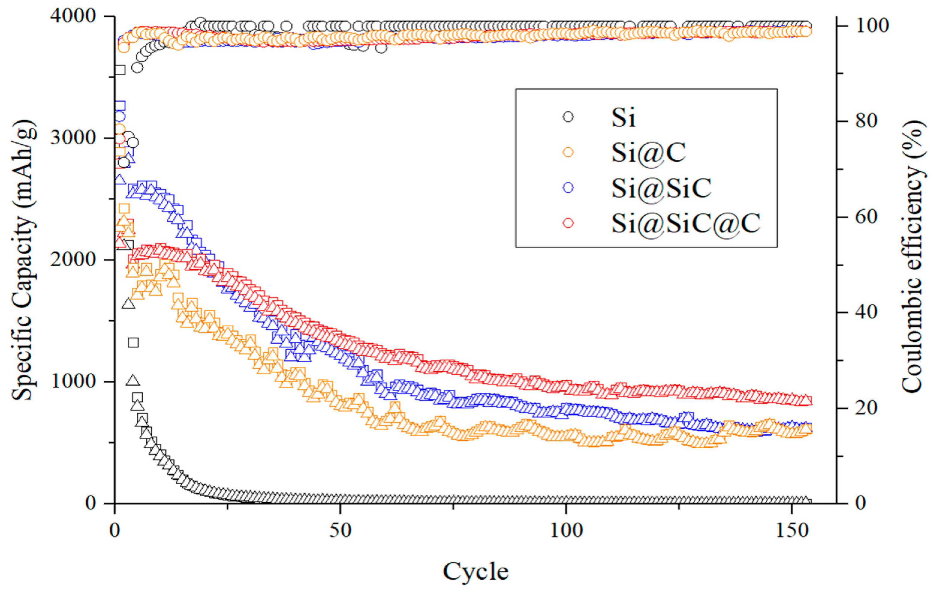
| Si | 0.2–0.5 | 2.03 | 78.3 | 9 | 6 |
| Si@RF | 0.2–0.5 | 1.68 | 78.9 | 665 | 474 |
| Si@SiC | 0.2–0.5 | 2.04 | 82.2 | 766 | 623 |
| Si@SiC@RF | 0.2–0.5 | 1.50 | 76.4 | 955 | 843 |
| Si@SiC@RF + Pre-Li | 0.2–0.5 | 1.50 | 97.1 | 970 | 774 |
Publisher’s Note: MDPI stays neutral with regard to jurisdictional claims in published maps and institutional affiliations. |
© 2021 by the authors. Licensee MDPI, Basel, Switzerland. This article is an open access article distributed under the terms and conditions of the Creative Commons Attribution (CC BY) license (http://creativecommons.org/licenses/by/4.0/).
Share and Cite
Tzeng, Y.; He, J.-L.; Jhan, C.-Y.; Wu, Y.-H. Effects of SiC and Resorcinol–Formaldehyde (RF) Carbon Coatings on Silicon-Flake-Based Anode of Lithium Ion Battery. Nanomaterials 2021, 11, 302. https://doi.org/10.3390/nano11020302
Tzeng Y, He J-L, Jhan C-Y, Wu Y-H. Effects of SiC and Resorcinol–Formaldehyde (RF) Carbon Coatings on Silicon-Flake-Based Anode of Lithium Ion Battery. Nanomaterials. 2021; 11(2):302. https://doi.org/10.3390/nano11020302
Chicago/Turabian StyleTzeng, Yonhua, Jia-Lin He, Cheng-Ying Jhan, and Yi-Hsuan Wu. 2021. "Effects of SiC and Resorcinol–Formaldehyde (RF) Carbon Coatings on Silicon-Flake-Based Anode of Lithium Ion Battery" Nanomaterials 11, no. 2: 302. https://doi.org/10.3390/nano11020302