Three-Dimensional Cathodes for Electrochemical Reduction of CO2: From Macro- to Nano-Engineering

Abstract
:1. Introduction
- (1)
- Overpotential, the difference between the thermodynamic and actual electrode reduction voltages. Overpotential is a measure of the energy efficiencies of the system.
- (2)
- Faradaic efficiency (FE), calculated by εFaraday = αnF/Q, where α is the number of electrons transferred, n is the number of moles for a given product, F is Faraday’s constant of 96,485 C mol−1, and Q is all the charge passed throughout the electrolysis process. FE describes the product selectivity in the reduction reaction, which is closely related to the reduction mechanism. Different reaction pathways are strongly affected by experimental conditions.
- (3)
- Current density (CD), obtained by dividing the total current by the surface area of the working electrode. CD reflects the rate of CO2 reaction.
- (4)
- Stability, degradation rate of CD over the period of system operation.
- (5)
- Tafel slope, derived from the plot of overpotential against the logarithm of partial CD, is an indicator for the reaction pathway and the rate-determining step.
- (1)
- Effective electrocatalysts to provide a low overpotential and high FE for the desired reactions;
- (2)
- A high electrical conductivity to minimize ohmic losses and a uniform current distribution (a mixed ionic and electronic conduction (MIEC) architecture benefits extension of reaction sites);
- (3)
- Porous architecture engineered from the macro- to nano-level to facilitate higher charge and mass transfer;
- (4)
- Mixed hydrophobic and hydrophilic properties for gas diffusion electrodes to avoid flooding while providing adsorptions;
- (5)
- Good mechanical and chemical stability to ensure an adequate lifetime;
- (6)
- Moderate costs.
- (1)
- Providing a larger number of electrochemical active sites;
- (2)
- Facilitating transport of reactants and even changing product distribution or selectivity;
- (3)
- Shortening ion and electron pathways;
- (4)
- Avoiding delamination of layered structures by free-standing design.
2. Self-Supported Nanocatalysts for 3D Cathodes
2.1. Nanocatalysts for CO2 Reduction
2.2. Advantages of Using Self-Supported Catalysts
- Excellent electron transfer and electrical conductivity due to interconnectedness of their structure;
- Maximal use of the active surface area due to absence of binder and inactive support particles covering a portion of active sites; and
- Enhanced mechanical stability due to absence of weak binder-catalyst-support interfaces.
2.3. Fabrication Techniques of Self-Supported Catalysts
2.4. Cases of Applications for CO2 Reduction
3. Nanofiber-Supported Nanocatalysts for 3D Cathodes
3.1. Polymer Nanofibers
3.2. Carbon Nanotubes and Nanofibers
3.3. Oxide Nanofibers
4. Graphene-Supported Nanocatalysts as Cathodes
- -
- Metal-free 3D graphene network (3DGNW);
- -
- Metal-free 3D graphene nanocompositions (3DGC);
- -
- Non-noble metal 3D graphene-based nanocomposite (NNM 3DGC); and
- -
- Noble metal 3D graphene-based nanocomposite (NM 3DGC).
4.1. Metal-Free 3D Graphene Network (3D-GNW)
4.2. Metal-Free 3D Graphene Nanocompositions (MF3DC)
4.3. Non-Noble Metal 3D Graphene-Based Nanocomposite (NNM3DGC)
4.4. Noble Metal 3D Graphene-Based Nanocomposite (NNM3DGC)
5. Porous Materials-Supported Nanocatalysts as 3D Cathodes
5.1. D Cathode with Metal-Based Catalysts
5.2. D Cathode with Carbon-Based Catalysts
5.3. D Cathode with MOFs/Single-Atom Metal Catalysts
6. Modeling and Simulation
6.1. Modeling Electrochemical CO2 Reduction
6.1.1. Intermediates and Reaction Pathway
6.1.2. Product Selectivity
6.2. Mass Transport Modeling in Nanostructured CO2RR Electrocatalysts
6.2.1. Modeling Mass Transport in a Porous CO2RR Gas Diffusion Electrode
6.2.2. Effect of Mass Transport of Catalyst Activity of 3D Nanowire Electrodes
7. Concluding Remarks
7.1. Current Status and Achievements
7.2. Remaining Challenges and Perspectives
Author Contributions
Funding
Acknowledgments
Conflicts of Interest
References
- Zhu, D.D.; Liu, J.L.; Qiao, S.Z. Recent advances in inorganic heterogeneous electrocatalysts for reduction of carbon dioxide. Adv. Mater. 2016, 28, 3423–3452. [Google Scholar] [CrossRef] [PubMed]
- Shi, J.; Jiang, Y.; Jiang, Z.; Wang, X.; Wang, X.; Zhang, S.; Han, P.; Yang, C. Enzymatic conversion of carbon dioxide. Chem. Soc. Rev. 2015, 44, 5981–6000. [Google Scholar] [CrossRef] [PubMed]
- Habisreutinger, S.N.; Schmidt-Mende, L.; Stolarczyk, J.K. Photocatalytic reduction of CO2 on TiO2 and other semiconductors. Angew. Chem. Int. Ed. 2013, 52, 7372–7408. [Google Scholar] [CrossRef] [PubMed]
- Grodkowski, J.; Neta, P. Copper-catalyzed radiolytic reduction of CO2 to CO in aqueous solutions. J. Phys. Chem. B 2001, 105, 4967–4972. [Google Scholar] [CrossRef]
- Wang, W.; Wang, S.; Ma, X.; Gong, J. Recent advances in catalytic hydrogenation of carbon dioxide. Chem. Soc. Rev. 2011, 40, 3703–3727. [Google Scholar] [CrossRef] [PubMed] [Green Version]
- Klankermayer, J.; Wesselbaum, S.; Beydoun, K.; Leitner, W. Selective catalytic synthesis using the combination of carbon dioxide and hydrogen: Catalytic chess at the interface of energy and chemistry. Angew. Chem. Int. Ed. 2016, 55, 7296–7343. [Google Scholar] [CrossRef]
- Singh, M.R.; Clark, E.L.; Bell, A.T. Thermodynamic and achievable efficiencies for solar-driven electrochemical reduction of carbon dioxide to transportation fuels. Proc. Natl. Acad. Sci. USA 2015, 112, E6111–E6118. [Google Scholar] [CrossRef] [Green Version]
- Olah, G.A.; Prakash, G.S.; Goeppert, A. Anthropogenic chemical carbon cycle for a sustainable future. J. Am. Chem. Soc. 2011, 133, 12881–12898. [Google Scholar] [CrossRef]
- Whipple, D.T.; Kenis, P.J. Prospects of CO2 utilization via direct heterogeneous electrochemical reduction. J. Phys. Chem. Lett. 2010, 1, 3451–3458. [Google Scholar] [CrossRef]
- Götz, M.; Lefebvre, J.; Mörs, F.; Koch, A.M.; Graf, F.; Bajohr, S.; Reimert, R.; Kolb, T. Renewable Power-to-Gas: A technological and economic review. Renew. Energy 2016, 85, 1371–1390. [Google Scholar] [CrossRef] [Green Version]
- Spurgeon, J.M.; Kumar, B. A comparative technoeconomic analysis of pathways for commercial electrochemical CO2 reduction to liquid products. Energy Environ. Sci. 2018, 11, 1536–1551. [Google Scholar] [CrossRef]
- Jouny, M.; Luc, W.; Jiao, F. General techno-economic analysis of CO2 electrolysis systems. Ind. Eng. Chem. Res. 2018, 57, 2165–2177. [Google Scholar] [CrossRef]
- Verma, S.; Kim, B.; Jhong, H.R.M.; Ma, S.; Kenis, P.J. A gross-margin model for defining technoeconomic benchmarks in the electroreduction of CO2. ChemSusChem 2016, 9, 1972–1979. [Google Scholar] [CrossRef] [PubMed]
- Ju, W.; Jiang, F.; Ma, H.; Pan, Z.; Zhao, Y.B.; Pagani, F.; Rentsch, D.; Wang, J.; Battaglia, C. Electrocatalytic Reduction of Gaseous CO2 to CO on Sn/Cu-Nanofiber-Based Gas Diffusion Electrodes. Adv. Energy Mater. 2019, 9, 1901514. [Google Scholar] [CrossRef]
- Oloman, C.; Li, H. Electrochemical processing of carbon dioxide. ChemSusChem 2008, 1, 385–391. [Google Scholar] [CrossRef] [PubMed]
- Nitopi, S.; Bertheussen, E.; Scott, S.B.; Liu, X.; Engstfeld, A.K.; Horch, S.; Seger, B.; Stephens, I.E.; Chan, K.; Hahn, C. Progress and perspectives of electrochemical CO2 reduction on copper in aqueous electrolyte. Chem. Rev. 2019, 119, 7610–7672. [Google Scholar] [CrossRef] [Green Version]
- Nwabara, U.O.; Cofell, E.R.; Verma, S.; Negro, E.; Kenis, P.J. Durable cathodes and electrolyzers for the efficient aqueous electrochemical reduction of CO2. ChemSusChem 2019, 13, 855–875. [Google Scholar] [CrossRef]
- Weekes, D.M.; Salvatore, D.A.; Reyes, A.; Huang, A.; Berlinguette, C.P. Electrolytic CO2 reduction in a flow cell. Acc. Chem. Res. 2018, 51, 910–918. [Google Scholar] [CrossRef]
- Perry, S.C.; Leung, P.-K.; Wang, L.; de León, C.P. Developments on carbon dioxide reduction: Their promise, achievements and challenges. Curr. Opin. Electrochem. 2020, 20, 88–98. [Google Scholar] [CrossRef]
- Song, Y.; Zhang, X.; Xie, K.; Wang, G.; Bao, X. High-Temperature CO2 Electrolysis in Solid Oxide Electrolysis Cells: Developments, Challenges, and Prospects. Adv. Mater. 2019, 31, 1902033. [Google Scholar] [CrossRef]
- Pander, J.E., III; Ren, D.; Huang, Y.; Loo, N.W.X.; Hong, S.H.L.; Yeo, B.S. Understanding the Heterogeneous Electrocatalytic Reduction of Carbon Dioxide on Oxide-Derived Catalysts. ChemElectroChem 2018, 5, 219–237. [Google Scholar] [CrossRef]
- Yang, K.D.; Lee, C.W.; Jang, J.H.; Ha, T.R.; Nam, K.T. Rise of nano effects in electrode during electrocatalytic CO2 conversion. Nanotechnology 2017, 28, 352001. [Google Scholar] [CrossRef] [PubMed]
- Kutz, R.B.; Chen, Q.; Yang, H.; Sajjad, S.D.; Liu, Z.; Masel, I.R. Sustainion Imidazolium-Functionalized Polymers for Carbon Dioxide Electrolysis. Energy Technol. 2017, 5, 929–936. [Google Scholar] [CrossRef] [Green Version]
- Fan, L.; Xia, C.; Yang, F.; Wang, J.; Wang, H.; Lu, Y. Strategies in catalysts and electrolyzer design for electrochemical CO2 reduction toward C2+ products. Sci. Adv. 2020, 6, eaay3111. [Google Scholar] [CrossRef] [Green Version]
- Kibria, M.G.; Edwards, J.P.; Gabardo, C.M.; Dinh, C.T.; Seifitokaldani, A.; Sinton, D.; Sargent, E.H. Electrochemical CO2 reduction into chemical feedstocks: From mechanistic electrocatalysis models to system design. Adv. Mater. 2019, 31, 1807166. [Google Scholar] [CrossRef]
- Zhang, S.; Fan, Q.; Xia, R.; Meyer, T.J. CO2 Reduction: From Homogeneous to Heterogeneous Electrocatalysis. Acc. Chem. Res. 2020, 53, 255–264. [Google Scholar] [CrossRef]
- Francke, R.; Schille, B.; Roemelt, M. Homogeneously catalyzed electroreduction of carbon dioxide—Methods, mechanisms, and catalysts. Chem. Rev. 2018, 118, 4631–4701. [Google Scholar] [CrossRef]
- Grills, D.C.; Matsubara, Y.; Kuwahara, Y.; Golisz, S.R.; Kurtz, D.A.; Mello, B.A. Electrocatalytic CO2 reduction with a homogeneous catalyst in ionic liquid: High catalytic activity at low overpotential. J. Phys. Chem. Lett. 2014, 5, 2033–2038. [Google Scholar] [CrossRef]
- Zhang, L.; Zhao, Z.J.; Gong, J. Nanostructured materials for heterogeneous electrocatalytic CO2 reduction and their related reaction mechanisms. Angew. Chem. Int. Ed. 2017, 56, 11326–11353. [Google Scholar] [CrossRef]
- Qiao, B.; Wang, A.; Yang, X.; Allard, L.F.; Jiang, Z.; Cui, Y.; Liu, J.; Li, J.; Zhang, T. Single-atom catalysis of CO oxidation using Pt1/FeOx. Nat. Chem. 2011, 3, 634–641. [Google Scholar] [CrossRef]
- He, H.; Jagvaral, Y. Electrochemical reduction of CO2 on graphene supported transition metals—Towards single atom catalysts. Phys. Chem. Chem. Phys. 2017, 19, 11436–11446. [Google Scholar] [CrossRef] [PubMed]
- Chen, Y.; Ji, S.; Chen, C.; Peng, Q.; Wang, D.; Li, Y. Single-atom catalysts: Synthetic strategies and electrochemical applications. Joule 2018, 2, 1242–1264. [Google Scholar] [CrossRef] [Green Version]
- Cui, X.; Li, W.; Ryabchuk, P.; Junge, K.; Beller, M. Bridging homogeneous and heterogeneous catalysis by heterogeneous single-metal-site catalysts. Nat. Catal. 2018, 1, 385–397. [Google Scholar] [CrossRef]
- Kim, D.; Resasco, J.; Yu, Y.; Asiri, A.M.; Yang, P. Synergistic geometric and electronic effects for electrochemical reduction of carbon dioxide using gold–copper bimetallic nanoparticles. Nat. Commun. 2014, 5, 1–8. [Google Scholar] [CrossRef] [Green Version]
- Liu, X.; Xiao, J.; Peng, H.; Hong, X.; Chan, K.; Nørskov, J.K. Understanding trends in electrochemical carbon dioxide reduction rates. Nat. Commun. 2017, 8, 1–7. [Google Scholar] [CrossRef] [PubMed]
- Mistry, H.; Reske, R.; Zeng, Z.; Zhao, Z.-J.; Greeley, J.; Strasser, P.; Cuenya, B.R. Exceptional size-dependent activity enhancement in the electroreduction of CO2 over Au nanoparticles. J. Am. Chem. Soc. 2014, 136, 16473–16476. [Google Scholar] [CrossRef]
- Reske, R.; Duca, M.; Oezaslan, M.; Schouten, K.J.P.; Koper, M.T.; Strasser, P. Controlling catalytic selectivities during CO2 electroreduction on thin Cu metal overlayers. J. Phys. Chem. Lett. 2013, 4, 2410–2413. [Google Scholar] [CrossRef]
- Zhu, W.; Zhang, Y.-J.; Zhang, H.; Lv, H.; Li, Q.; Michalsky, R.; Peterson, A.A.; Sun, S. Active and selective conversion of CO2 to CO on ultrathin Au nanowires. J. Am. Chem. Soc. 2014, 136, 16132–16135. [Google Scholar] [CrossRef]
- Zhu, W.; Michalsky, R.; Metin, O.N.; Lv, H.; Guo, S.; Wright, C.J.; Sun, X.; Peterson, A.A.; Sun, S. Monodisperse Au nanoparticles for selective electrocatalytic reduction of CO2 to CO. J. Am. Chem. Soc. 2013, 135, 16833–16836. [Google Scholar] [CrossRef]
- Liu, S.; Wang, X.-Z.; Tao, H.; Li, T.; Liu, Q.; Xu, Z.; Fu, X.-Z.; Luo, J.-L. Ultrathin 5-fold twinned sub-25 nm silver nanowires enable highly selective electroreduction of CO2 to CO. Nano Energy 2018, 45, 456–462. [Google Scholar] [CrossRef]
- Sen, S.; Liu, D.; Palmore, G.T.R. Electrochemical reduction of CO2 at copper nanofoams. ACS Catal. 2014, 4, 3091–3095. [Google Scholar] [CrossRef]
- Loiudice, A.; Lobaccaro, P.; Kamali, E.A.; Thao, T.; Huang, B.H.; Ager, J.W.; Buonsanti, R. Tailoring copper nanocrystals towards C2 products in electrochemical CO2 reduction. Angew. Chem. Int. Ed. 2016, 55, 5789–5792. [Google Scholar] [CrossRef] [PubMed] [Green Version]
- Hall, A.S.; Yoon, Y.; Wuttig, A.; Surendranath, Y. Mesostructure-Induced Selectivity in CO2 Reduction Catalysis. J. Am. Chem. Soc. 2015, 137, 14834–14837. [Google Scholar] [CrossRef] [PubMed] [Green Version]
- Min, X.; Kanan, M.W. Pd-Catalyzed Electrohydrogenation of Carbon Dioxide to Formate: High Mass Activity at Low Overpotential and Identification of the Deactivation Pathway. J. Am. Chem. Soc. 2015, 137, 4701–4708. [Google Scholar] [CrossRef]
- Cave, E.R.; Shi, C.; Kuhl, K.P.; Hatsukade, T.; Abram, D.N.; Hahn, C.; Chan, K.; Jaramillo, T.F. Trends in the Catalytic Activity of Hydrogen Evolution during CO2 Electroreduction on Transition Metals. ACS Catal. 2018, 8, 3035–3040. [Google Scholar] [CrossRef]
- Hong, X.; Chan, K.; Tsai, C.; Norskov, J.K. How Doped MoS2 Breaks Transition-Metal Scaling Relations for CO2 Electrochemical Reduction. ACS Catal. 2016, 6, 4428–4437. [Google Scholar] [CrossRef]
- Li, Y.; Sun, Q. Recent Advances in Breaking Scaling Relations for Effective Electrochemical Conversion of CO2. Adv. Energy Mater. 2016, 6, 1600463. [Google Scholar] [CrossRef]
- Schouten, K.J.P.; Gallent, E.P.; Koper, M.T.M. The influence of pH on the reduction of CO and CO2 to hydrocarbons on copper electrodes. J. Electroanal. Chem. 2014, 716, 53–57. [Google Scholar] [CrossRef]
- Pang, Y.; Burdyny, T.; Dinh, C.-T.; Kibria, G.; Fan, J.Z.; Liu, M.; Sargent, E.H.; Sinton, D. Joint tuning of nanostructured Cu-oxide morphology and local electrolyte programs high-rate CO2 reduction to C2H4. Green Chem. 2017, 19, 4023–4030. [Google Scholar] [CrossRef]
- Zhang, Y.; Zhang, X.; Bond, A.M.; Zhang, J. Identification of a new substrate effect that enhances the electrocatalytic activity of dendritic tin in CO2 reduction. Phys. Chem. Chem. Phys. 2018, 20, 5936–5941. [Google Scholar] [CrossRef]
- Lim, C.; Harrington, D.A.; Marshall, A. Effects of mass transfer on the electrocatalytic CO2 reduction on Cu. Electrochim. Acta 2017, 238, 56–63. [Google Scholar] [CrossRef]
- Kas, R.; Kortlever, R.; Yilmaz, H.; Koper, M.T.M.; Mul, G.; Yilmaz, H. Manipulating the Hydrocarbon Selectivity of Copper Nanoparticles in CO2 Electroreduction by Process Conditions. ChemElectroChem 2014, 2, 354–358. [Google Scholar] [CrossRef]
- Varela, A.S.; Kroschel, M.; Reier, T.; Strasser, P. Controlling the selectivity of CO2 electroreduction on copper: The effect of the electrolyte concentration and the importance of the local pH. Catal. Today 2016, 260, 8–13. [Google Scholar] [CrossRef]
- Resasco, J.; Chen, L.D.; Clark, E.L.; Tsai, C.; Hahn, C.; Jaramillo, T.F.; Chan, K.; Bell, A.T. Promoter Effects of Alkali Metal Cations on the Electrochemical Reduction of Carbon Dioxide. J. Am. Chem. Soc. 2017, 139, 11277–11287. [Google Scholar] [CrossRef] [Green Version]
- Ayemoba, O.; Cuesta, A. Spectroscopic Evidence of Size-Dependent Buffering of Interfacial pH by Cation Hydrolysis during CO2 Electroreduction. ACS Appl. Mater. Interfaces 2017, 9, 27377–27382. [Google Scholar] [CrossRef] [Green Version]
- Pérez-Gallent, E.; Marcandalli, G.; Figueiredo, M.C.; Calle-Vallejo, F.; Koper, M.T.M. Structure- and Potential-Dependent Cation Effects on CO Reduction at Copper Single-Crystal Electrodes. J. Am. Chem. Soc. 2017, 139, 16412–16419. [Google Scholar] [CrossRef]
- Singh, M.R.; Kwon, Y.; Lum, Y.; Ager, J.W.; Bell, A.T. Hydrolysis of Electrolyte Cations Enhances the Electrochemical Reduction of CO2 over Ag and Cu. J. Am. Chem. Soc. 2016, 138, 13006–13012. [Google Scholar] [CrossRef] [Green Version]
- Burdyny, T.; Smith, W.A. CO2 reduction on gas-diffusion electrodes and why catalytic performance must be assessed at commercially-relevant conditions. Energy Environ. Sci. 2019, 12, 1442–1453. [Google Scholar] [CrossRef] [Green Version]
- Su, T.; Li, Y.; Xue, S.; Xu, Z.; Zheng, M.; Xia, C. Kinetics of CO2 electrolysis on composite electrodes consisting of Cu and samaria-doped ceria. J. Mater. Chem. A 2019, 7, 1598–1606. [Google Scholar] [CrossRef]
- Bhattacharyya, B. Electrochemical Micromachining for Nanofabrication, MEMS and Nanotechnology; William Andrew: Norwich, NY, USA, 2015. [Google Scholar]
- Chmielowiec, B.; Fujimura, T.; Otani, T.; Aoyama, K.; Nohira, T.; Homma, T.; Fukunaka, Y.; Allanore, A. Experimental Measurement of Overpotential Sources during Anodic Gas Evolution in Aqueous and Molten Salt Systems. J. Electrochem. Soc. 2019, 166, E323–E329. [Google Scholar] [CrossRef]
- Cao, L.; Raciti, D.; Li, C.; Livi, K.J.T.; Rottmann, P.F.; Hemker, K.J.; Mueller, T.; Wang, C. Mechanistic Insights for Low-Overpotential Electroreduction of CO2 to CO on Copper Nanowires. ACS Catal. 2017, 7, 8578–8587. [Google Scholar] [CrossRef]
- Kumar, B.; Brian, J.P.; Atla, V.; Kumari, S.; Bertram, K.A.; White, R.T.; Spurgeon, J.M. New trends in the development of heterogeneous catalysts for electrochemical CO2 reduction. Catal. Today 2016, 270, 19–30. [Google Scholar] [CrossRef]
- Yu, F.; Wei, P.; Yang, Y.; Chen, Y.; Guo, L.; Peng, Z. Material design at nano and atomic scale for electrocatalytic CO2 reduction. Nano Mater. Sci. 2019, 1, 60–69. [Google Scholar] [CrossRef]
- Zhang, W.; Hu, Y.; Ma, L.; Zhu, G.; Wang, Y.; Xue, X.; Chen, R.; Yang, S.; Jin, Z. Progress and Perspective of Electrocatalytic CO2 Reduction for Renewable Carbonaceous Fuels and Chemicals. Adv. Sci. 2017, 5, 1700275. [Google Scholar] [CrossRef] [PubMed]
- Khezri, B.; Fisher, A.C.; Pumera, M. CO2reduction: The quest for electrocatalytic materials. J. Mater. Chem. A 2017, 5, 8230–8246. [Google Scholar] [CrossRef]
- Duan, X.; Xu, J.; Wei, Z.; Ma, J.; Guo, S.; Wang, Q.; Liu, H.; Dou, S.X. Metal-Free Carbon Materials for CO2Electrochemical Reduction. Adv. Mater. 2017, 29, 1701784. [Google Scholar] [CrossRef]
- He, J.; Johnson, N.J.; Huang, A.; Berlinguette, C.P. Electrocatalytic Alloys for CO2 Reduction. ChemSusChem 2017, 11, 48–57. [Google Scholar] [CrossRef]
- Raciti, D.; Wang, C. Recent Advances in CO2 Reduction Electrocatalysis on Copper. ACS Energy Lett. 2018, 3, 1545–1556. [Google Scholar] [CrossRef]
- Chang, Z.; Huo, S.; Zhang, W.; Fang, J.; Wang, H. The Tunable and Highly Selective Reduction Products on Ag@Cu Bimetallic Catalysts Toward CO2 Electrochemical Reduction Reaction. J. Phys. Chem. C 2017, 121, 11368–11379. [Google Scholar] [CrossRef]
- Weng, Z.; Zhang, X.; Wu, Y.; Huo, S.; Jiang, J.; Liu, W.; He, G.; Liang, Y.; Wang, H. Self-Cleaning Catalyst Electrodes for Stabilized CO2 Reduction to Hydrocarbons. Angew. Chem. 2017, 129, 13315–13319. [Google Scholar] [CrossRef]
- Reske, R.; Mistry, H.; Behafarid, F.; Cuenya, B.R.; Strasser, P. Particle Size Effects in the Catalytic Electroreduction of CO2 on Cu Nanoparticles. J. Am. Chem. Soc. 2014, 136, 6978–6986. [Google Scholar] [CrossRef]
- Gao, D.; Zhou, H.; Wang, J.; Miao, S.; Yang, F.; Wang, G.; Wang, J.; Bao, X. Size-Dependent Electrocatalytic Reduction of CO2over Pd Nanoparticles. J. Am. Chem. Soc. 2015, 137, 4288–4291. [Google Scholar] [CrossRef]
- Koh, J.H.; Won, D.H.; Eom, T.; Kim, N.-K.; Jung, K.D.; Kim, H.; Hwang, Y.J.; Min, B.K. Facile CO2 Electro-Reduction to Formate via Oxygen Bidentate Intermediate Stabilized by High-Index Planes of Bi Dendrite Catalyst. ACS Catal. 2017, 7, 5071–5077. [Google Scholar] [CrossRef]
- Song, J.T.; Ryoo, H.; Cho, M.; Kim, J.; Kim, J.-G.; Chung, S.-Y.; Oh, J. CO2 Reduction: Nanoporous Au Thin Films on Si Photoelectrodes for Selective and Efficient Photoelectrochemical CO2 Reduction. Adv. Energy Mater. 2017, 7, 1601103. [Google Scholar] [CrossRef]
- Feng, X.; Jiang, K.; Fan, S.; Kanan, M.W. Grain-Boundary-Dependent CO2 Electroreduction Activity. J. Am. Chem. Soc. 2015, 137, 4606–4609. [Google Scholar] [CrossRef] [PubMed]
- Fujita, T.; Guan, P.; McKenna, K.; Lang, X.; Hirata, A.; Zhang, L.; Tokunaga, T.; Arai, S.; Yamamoto, Y.; Tanaka, N.; et al. Atomic origins of the high catalytic activity of nanoporous gold. Nat. Mater. 2012, 11, 775–780. [Google Scholar] [CrossRef]
- Hossain, M.N.; Liu, Z.; Wen, J.; Chenb, A. Enhanced catalytic activity of nanoporous Au for the efficient electrochemical reduction of carbon dioxide. Appl. Catal. B Environ. 2018, 236, 483–489. [Google Scholar] [CrossRef]
- Yoon, Y.; Hall, A.S.; Surendranath, Y. Tuning of Silver Catalyst Mesostructure Promotes Selective Carbon Dioxide Conversion into Fuels. Angew. Chem. Int. Ed. 2016, 55, 15282–15286. [Google Scholar] [CrossRef] [Green Version]
- Abild-Pedersen, F.; Greeley, J.; Studt, F.; Rossmeisl, J.; Munter, T.R.; Moses, P.G.; Skúlason, E.; Bligaard, T.; Nørskov, J.K. Scaling Properties of Adsorption Energies for Hydrogen-Containing Molecules on Transition-Metal Surfaces. Phys. Rev. Lett. 2007, 99, 016105. [Google Scholar] [CrossRef] [Green Version]
- Koh, J.H.; Jeon, H.S.; Jee, M.S.; Nursanto, E.B.; Lee, H.; Hwang, Y.J.; Min, B.K. Oxygen Plasma Induced Hierarchically Structured Gold Electrocatalyst for Selective Reduction of Carbon Dioxide to Carbon Monoxide. J. Phys. Chem. C 2014, 119, 883–889. [Google Scholar] [CrossRef]
- Kim, C.; Eom, T.; Jee, M.S.; Jung, H.; Kim, H.; Min, B.K.; Hwang, Y.J. Insight into Electrochemical CO2 Reduction on Surface-Molecule-Mediated Ag Nanoparticles. ACS Catal. 2016, 7, 779–785. [Google Scholar] [CrossRef]
- Gao, S.; Lin, Y.; Jiao, X.; Sun, Y.; Luo, Q.; Zhang, W.H.; Li, D.; Yang, J.; Xie, Y. Partially oxidized atomic cobalt layers for carbon dioxide electroreduction to liquid fuel. Nat. 2016, 529, 68–71. [Google Scholar] [CrossRef] [PubMed]
- Sun, Y.; Lei, F.; Gao, S.; Pan, B.C.; Zhou, J.; Xie, Y. Atomically Thin Tin Dioxide Sheets for Efficient Catalytic Oxidation of Carbon Monoxide. Angew. Chem. 2013, 125, 10763–10766. [Google Scholar] [CrossRef]
- Jiang, K.; Kharel, P.; Peng, Y.; Gangishetty, M.K.; Lin, H.-Y.G.; Stavitski, E.; Attenkofer, K.; Wang, H. Silver Nanoparticles with Surface-Bonded Oxygen for Highly Selective CO2 Reduction. ACS Sustain. Chem. Eng. 2017, 5, 8529–8534. [Google Scholar] [CrossRef]
- Tan, Y.C.; Lee, K.B.; Song, H.; Oh, J. Modulating Local CO2 Concentration as a General Strategy for Enhancing C−C Coupling in CO2 Electroreduction. Joule 2020, 4, 1104–1120. [Google Scholar] [CrossRef]
- Walsh, F.C.; Arenas, L.F.; De León, C.P. Developments in electrode design: Structure, decoration and applications of electrodes for electrochemical technology. J. Chem. Technol. Biotechnol. 2018, 93, 3073–3090. [Google Scholar] [CrossRef] [Green Version]
- Sun, Z.; Ma, T.; Tao, H.; Fan, Q.; Han, B. Fundamentals and Challenges of Electrochemical CO2 Reduction Using Two-Dimensional Materials. Chem 2017, 3, 560–587. [Google Scholar] [CrossRef] [Green Version]
- König, M.; Vaes, J.; Klemm, E.; Pant, D. Solvents and Supporting Electrolytes in the Electrocatalytic Reduction of CO2. Science 2019, 19, 135–160. [Google Scholar] [CrossRef]
- Faggion, D.J.; Gonçalves, W.D.G.; Dupont, J. CO2 Electroreduction in Ionic Liquids. Front. Chem. 2019, 7, 102. [Google Scholar] [CrossRef] [Green Version]
- Feng, J.; Zeng, S.; Feng, J.; Dong, H.; Zhang, S. CO2 Electroreduction in Ionic Liquids: A Review. Chin. J. Chem. 2018, 36, 961–970. [Google Scholar] [CrossRef]
- Kas, R.; Hummadi, K.K.; Kortlever, R.; De Wit, P.; Milbrat, A.; Luiten-Olieman, M.W.J.; Benes, N.E.; Koper, M.T.M.; Mul, G. Three-dimensional porous hollow fibre copper electrodes for efficient and high-rate electrochemical carbon dioxide reduction. Nat. Commun. 2016, 7, 10748. [Google Scholar] [CrossRef] [PubMed] [Green Version]
- Lv, J.-J.; Jouny, M.; Luc, W.; Zhu, W.; Zhu, J.-J.; Jiao, F. A Highly Porous Copper Electrocatalyst for Carbon Dioxide Reduction. Adv. Mater. 2018, 30, 1803111. [Google Scholar] [CrossRef] [PubMed]
- Han, L.; Zhou, W.; Xiang, C. High-Rate Electrochemical Reduction of Carbon Monoxide to Ethylene Using Cu-Nanoparticle-Based Gas Diffusion Electrodes. ACS Energy Lett. 2018, 3, 855–860. [Google Scholar] [CrossRef] [Green Version]
- De Arquer, F.P.G.; Dinh, C.-T.; Ozden, A.; Wicks, J.; McCallum, C.; Kirmani, A.R.; Nam, D.-H.; Gabardo, C.M.; Seifitokaldani, A.; Wang, X.; et al. CO2 electrolysis to multicarbon products at activities greater than 1 A cm−2. Science 2020, 367, 661–666. [Google Scholar] [CrossRef] [PubMed]
- Dinh, C.-T.; Burdyny, T.; Kibria, G.; Seifitokaldani, A.; Gabardo, C.M.; De Arquer, F.P.G.; Kiani, A.; Edwards, J.P.; De Luna, P.; Bushuyev, O.S.; et al. CO2 electroreduction to ethylene via hydroxide-mediated copper catalysis at an abrupt interface. Science 2018, 360, 783–787. [Google Scholar] [CrossRef] [PubMed] [Green Version]
- Abe, T.; Yoshida, T.; Tokita, S.; Taguchi, F.; Imaya, H.; Kaneko, M. Factors affecting selective electrocatalytic CO2 reduction with cobalt phthalocyanine incorporated in a polyvinylpyridine membrane coated on a graphite electrode. J. Electroanal. Chem. 1996, 412, 125–132. [Google Scholar] [CrossRef]
- Li, F.; Macfarlane, D.R.; Zhang, J.; Macfarlane, D. Recent advances in the nanoengineering of electrocatalysts for CO2reduction. Nanoscale 2018, 10, 6235–6260. [Google Scholar] [CrossRef]
- Weng, L.-C.; Bell, A.T.; Weber, A.Z. Modeling gas-diffusion electrodes for CO2 reduction. Phys. Chem. Chem. Phys. 2018, 20, 16973–16984. [Google Scholar] [CrossRef] [Green Version]
- Salvatore, D.A.; Weekes, D.M.; He, J.; Dettelbach, K.E.; Li, Y.C.; Mallouk, T.E.; Berlinguette, C.P. Electrolysis of Gaseous CO2 to CO in a Flow Cell with a Bipolar Membrane. ACS Energy Lett. 2017, 3, 149–154. [Google Scholar] [CrossRef]
- Jeanty, P.; Scherer, C.; Magori, E.; Wiesner-Fleischer, K.; Hinrichsen, O.; Fleischer, M. Upscaling and continuous operation of electrochemical CO2 to CO conversion in aqueous solutions on silver gas diffusion electrodes. J. CO2 Util. 2018, 24, 454–462. [Google Scholar] [CrossRef]
- Dullien, F.A.L. Porous Media: Fluid Transport and Pore Structure; Academic Press: Cambridge, MA, USA, 1992; 574p. [Google Scholar]
- Jhong, H.-R.M.; Brushett, F.R.; Yin, L.; Stevenson, D.M.; Kenis, P.J.A. Combining Structural and Electrochemical Analysis of Electrodes Using Micro-Computed Tomography and a Microfluidic Fuel Cell. J. Electrochem. Soc. 2012, 159, B292–B298. [Google Scholar] [CrossRef] [Green Version]
- Hyun, G.; Song, J.T.; Ahn, C.; Ham, Y.; Cho, D.; Oh, J.; Jeon, S. Hierarchically porous Au nanostructures with interconnected channels for efficient mass transport in electrocatalytic CO2 reduction. Proc. Natl. Acad. Sci. USA 2020, 117, 5680–5685. [Google Scholar] [CrossRef] [PubMed]
- Flexer, V.; Jourdin, L. Purposely Designed Hierarchical Porous Electrodes for High Rate Microbial Electrosynthesis of Acetate from Carbon Dioxide. Acc. Chem. Res. 2020, 53, 311–321. [Google Scholar] [CrossRef] [PubMed]
- He, G.; Tang, H.; Wang, H.; Bian, Z. Highly Selective and Active Pd-In/three-dimensional Graphene with Special Structure for Electroreduction CO2 to Formate. Electroanalysis 2017, 30, 84–93. [Google Scholar] [CrossRef]
- Li, J.; Chen, G.; Zhu, Y.; Liang, Z.; Pei, A.; Wu, C.-L.; Wang, H.; Lee, H.R.; Liu, K.; Chu, S.; et al. Efficient electrocatalytic CO2 reduction on a three-phase interface. Nat. Catal. 2018, 1, 592–600. [Google Scholar] [CrossRef]
- Raciti, D.; Wang, Y.; Park, J.H.; Wang, C. Three-Dimensional Hierarchical Copper-Based Nanostructures as Advanced Electrocatalysts for CO2 Reduction. ACS Appl. Energy Mater. 2018, 1, 2392–2398. [Google Scholar] [CrossRef]
- Burdyny, T.; Graham, P.J.; Pang, Y.; Dinh, C.-T.; Liu, M.; Sargent, E.H.; Sinton, D. Nanomorphology-Enhanced Gas-Evolution Intensifies CO2 Reduction Electrochemistry. ACS Sustain. Chem. Eng. 2017, 5, 4031–4040. [Google Scholar] [CrossRef]
- Sacco, A.; Zeng, J.; Bejtka, K.; Chiodoni, A. Modeling of gas bubble-induced mass transport in the electrochemical reduction of carbon dioxide on nanostructured electrodes. J. Catal. 2019, 372, 39–48. [Google Scholar] [CrossRef]
- Arthur, T.S.; Bates, D.J.; Cirigliano, N.; Johnson, D.C.; Malati, P.; Mosby, J.M.; Perre, E.; Rawls, M.T.; Prieto, A.L.; Dunn, B. Three-dimensional electrodes and battery architectures. MRS Bull. 2011, 36, 523–531. [Google Scholar] [CrossRef] [Green Version]
- Liu, L.; Zhao, H.; Lei, Y. Advances on three-dimensional electrodes for micro-supercapacitors: A mini-review. InfoMat 2019, 1, 74–84. [Google Scholar] [CrossRef] [Green Version]
- Kauffman, D.R.; Thakkar, J.; Siva, R.; Matranga, C.; Ohodnicki, P.R.; Zeng, C.; Jin, R. Efficient Electrochemical CO2 Conversion Powered by Renewable Energy. ACS Appl. Mater. Interfaces 2015, 7, 15626–15632. [Google Scholar] [CrossRef] [PubMed]
- Lum, Y.; Yue, B.; Lobaccaro, P.; Bell, A.T.; Ager, J.W. Optimizing C–C Coupling on Oxide-Derived Copper Catalysts for Electrochemical CO2 Reduction. J. Phys. Chem. C 2017, 121, 14191–14203. [Google Scholar] [CrossRef] [Green Version]
- Raciti, D.; Mao, M.; Wang, C. Mass transport modelling for the electroreduction of CO2 on Cu nanowires. Nanotechnology 2017, 29, 044001. [Google Scholar] [CrossRef]
- Raciti, D.; Livi, K.J.; Wang, C. Highly Dense Cu Nanowires for Low-Overpotential CO2 Reduction. Nano Lett. 2015, 15, 6829–6835. [Google Scholar] [CrossRef]
- Haichao, L.; Haoyi, L.; Bubakir, M.M.; Weimin, Y.; Barhoum, A. Engineering Nanofibers as Electrode and Membrane Materials for Batteries, Supercapacitors, and Fuel Cells; Springer Science and Business Media: Berlin/Heidelberg, Germany, 2018; pp. 1–27. [Google Scholar]
- Yang, Z.; Ren, J.; Zhang, Z.; Chen, X.; Guan, G.; Qiu, L.; Zhang, Y.; Peng, H. Recent Advancement of Nanostructured Carbon for Energy Applications. Chem. Rev. 2015, 115, 5159–5223. [Google Scholar] [CrossRef]
- Li, J.; Liu, K.; Gao, X.; Yao, B.; Huo, K.; Cheng, Y.; Cheng, X.; Chen, D.; Wang, B.; Sun, W.; et al. Oxygen- and Nitrogen-Enriched 3D Porous Carbon for Supercapacitors of High Volumetric Capacity. ACS Appl. Mater. Interfaces 2015, 7, 24622–24628. [Google Scholar] [CrossRef] [PubMed]
- Duan, B.; Gao, X.; Yao, X.; Fang, Y.; Huang, L.; Zhou, J.; Zhang, L. Unique elastic N-doped carbon nanofibrous microspheres with hierarchical porosity derived from renewable chitin for high rate supercapacitors. Nano Energy 2016, 27, 482–491. [Google Scholar] [CrossRef]
- Hao, J.; Shi, W. Transition metal (Mo, Fe, Co, and Ni)-based catalysts for electrochemical CO2 reduction. Chin. J. Catal. 2018, 39, 1157–1166. [Google Scholar] [CrossRef]
- Verma, S.; Hamasaki, Y.; Kim, C.; Huang, W.; Lu, S.; Jhong, H.-R.M.; Gewirth, A.A.; Fujigaya, T.; Nakashima, N.; Kenis, P.J.A. Insights into the Low Overpotential Electroreduction of CO2 to CO on a Supported Gold Catalyst in an Alkaline Flow Electrolyzer. ACS Energy Lett. 2017, 3, 193–198. [Google Scholar] [CrossRef]
- Nursanto, E.B.; Jeon, H.S.; Kim, C.; Jee, M.S.; Koh, J.H.; Hwang, Y.J.; Min, B.K. Gold catalyst reactivity for CO2 electro-reduction: From nano particle to layer. Catal. Today 2016, 260, 107–111. [Google Scholar] [CrossRef]
- Dutta, A.; Rahaman, M.; Mohos, M.; Zanetti, A.; Broekmann, P. Electrochemical CO2 Conversion Using Skeleton (Sponge) Type of Cu Catalysts. ACS Catal. 2017, 7, 5431–5437. [Google Scholar] [CrossRef]
- Hori, Y.; Murata, A.; Takahashi, R. Formation of hydrocarbons in the electrochemical reduction of carbon dioxide at a copper electrode in aqueous solution. J. Chem. Soc. Faraday Trans. 1 Phys. Chem. Condens. Phases 1989, 85, 2309–2326. [Google Scholar] [CrossRef]
- Varela, A.S.; Ju, W.; Strasser, P. Molecular nitrogen—Carbon catalysts, solid metal organic framework catalysts, and solid metal/nitrogen-doped carbon (MNC) catalysts for the electrochemical CO2 reduction. Adv. Energy Mater. 2018, 8, 1703614. [Google Scholar] [CrossRef] [Green Version]
- Sreekanth, N.; Nazrulla, M.A.; Vineesh, T.V.; Sailaja, K.; Phani, K.L. Metal-free boron-doped graphene for selective electroreduction of carbon dioxide to formic acid/formate. Chem. Commun. 2015, 51, 16061–16064. [Google Scholar] [CrossRef]
- Han, P.; Yu, X.; Yuan, D.; Kuang, M.; Wang, Y.; Al-Enizi, A.M.; Zheng, G. Defective graphene for electrocatalytic CO2 reduction. J. Colloid Interface Sci. 2019, 534, 332–337. [Google Scholar] [CrossRef]
- Sharma, P.P.; Wu, J.; Yadav, T.; Liu, M.; Wright, C.J.; Tiwary, C.S.; Yakobson, B.I.; Lou, J.; Ajayan, P.M.; Zhou, X.-D. Nitrogen-Doped Carbon Nanotube Arrays for High-Efficiency Electrochemical Reduction of CO2: On the Understanding of Defects, Defect Density, and Selectivity. Angew. Chem. 2015, 127, 13905–13909. [Google Scholar] [CrossRef]
- Wu, J.; Yadav, T.; Liu, M.; Sharma, P.P.; Tiwary, C.S.; Ma, L.; Zou, X.; Zhou, X.-D.; Yakobson, B.I.; Lou, J.; et al. Achieving Highly Efficient, Selective, and Stable CO2 Reduction on Nitrogen-Doped Carbon Nanotubes. ACS Nano 2015, 9, 5364–5371. [Google Scholar] [CrossRef]
- Wanninayake, N.; Ai, Q.; Zhou, R.; Hoque, A.; Herrell, S.; Guzman, M.I.; Risko, C.; Kim, D.Y. Understanding the effect of host structure of nitrogen doped ultrananocrystalline diamond electrode on electrochemical carbon dioxide reduction. Carbon 2020, 157, 408–419. [Google Scholar] [CrossRef]
- Li, Y.; Zou, B.; Hu, C.; Cao, M. Nitrogen-doped porous carbon nanofiber webs for efficient CO2 capture and conversion. Carbon 2016, 99, 79–89. [Google Scholar] [CrossRef]
- Li, F.; Xue, M.; Knowles, G.P.; Chen, L.; Macfarlane, D.R.; Zhang, J. Porous nitrogen–doped carbon derived from biomass for electrocatalytic reduction of CO2 to CO. Electrochim. Acta 2017, 245, 561–568. [Google Scholar] [CrossRef]
- Hursán, D.; Samu, A.A.; Janovák, L.; Artyushkova, K.; Asset, T.; Atanassov, P.; Janáky, C. Morphological Attributes Govern Carbon Dioxide Reduction on N-Doped Carbon Electrodes. Joule 2019, 3, 1719–1733. [Google Scholar] [CrossRef] [PubMed] [Green Version]
- Liu, S.; Yang, H.; Huang, X.; Liu, L.; Cai, W.; Gao, J.; Li, X.; Zhang, T.; Huang, Y.; Liu, B. Identifying Active Sites of Nitrogen-Doped Carbon Materials for the CO2 Reduction Reaction. Adv. Funct. Mater. 2018, 28, 1800499. [Google Scholar] [CrossRef]
- Wu, J.; Liu, M.; Sharma, P.P.; Yadav, T.; Ma, L.; Yang, Y.; Zou, X.; Zhou, X.-D.; Vajtai, R.; Yakobson, B.I.; et al. Incorporation of Nitrogen Defects for Efficient Reduction of CO2 via Two-Electron Pathway on Three-Dimensional Graphene Foam. Nano Lett. 2015, 16, 466–470. [Google Scholar] [CrossRef]
- Wang, H.; Chen, Y.; Hou, X.; Ma, C.; Tan, T. Nitrogen-doped graphenes as efficient electrocatalysts for the selective reduction of carbon dioxide to formate in aqueous solution. Green Chem. 2016, 18, 3250–3256. [Google Scholar] [CrossRef]
- Jeong, H.Y.; Balamurugan, M.; Choutipalli, V.S.K.; Jo, J.; Baik, H.; Subramanian, V.; Kim, M.; Sim, U.; Nam, K.T. Tris (2-benzimidazolylmethyl) amine-directed synthesis of single-atom nickel catalysts for electrochemical CO production from CO2. Chem. A Eur. J. 2018, 24, 18444–18454. [Google Scholar] [CrossRef] [PubMed]
- Rong, X.; Wang, H.-J.; Lu, X.-L.; Si, R.; Lu, T.-B. Controlled Synthesis of a Vacancy-Defect Single-Atom Catalyst for Boosting CO2 Electroreduction. Angew. Chem. Int. Ed. 2020, 59, 1961–1965. [Google Scholar] [CrossRef]
- Zheng, T.; Jiang, K.; Ta, N.; Hu, Y.; Zeng, J.; Liu, J.; Wang, H. Large-Scale and Highly Selective CO2 Electrocatalytic Reduction on Nickel Single-Atom Catalyst. Joule 2019, 3, 265–278. [Google Scholar] [CrossRef] [Green Version]
- Allen, B.C.; Mote, M.W.; Sabroff, A.M. Method of Making Foamed Metal. U.S. Patent 3,087,807, 30 April 1963. [Google Scholar]
- Quadbeck, P.; Stephani, G.; Kümmel, K.; Adler, J.; Standke, G. Synthesis and Properties of Open-Celled Metal Foams. Mater. Sci. Forum 2007, 1005–1008. [Google Scholar] [CrossRef]
- Vereecken, P.M.; Binstead, R.A.; Deligianni, H.; Andricacos, P.C. The chemistry of additives in damascene copper plating. IBM J. Res. Dev. 2005, 49, 3–18. [Google Scholar] [CrossRef]
- Moffat, T.; Wheeler, D.; Josell, D. Electrodeposition of Copper in the SPS-PEG-Cl Additive System. J. Electrochem. Soc. 2004, 151, C262–C271. [Google Scholar] [CrossRef]
- Moffat, T.; Wheeler, D.; Kim, S.-K.; Josell, D. Curvature Enhanced Adsorbate Coverage Model for Electrodeposition. J. Electrochem. Soc. 2006, 153, C127–C132. [Google Scholar] [CrossRef] [Green Version]
- Kim, J.-H.; Kim, R.-H.; Kwon, H. Preparation of copper foam with 3-dimensionally interconnected spherical pore network by electrodeposition. Electrochem. Commun. 2008, 10, 1148–1151. [Google Scholar] [CrossRef]
- Jeon, S.; Ahn, C. Method of Fabricating 3d Nanostructured Metal Oxides Using Proximity-Field Nanopatterning and Atomic Layer Deposition. U.S. Patent App. 14/097,971, 27 November 2014. [Google Scholar]
- Jeon, S.; Park, J.-U.; Cirelli, R.; Yang, S.; Heitzman, C.E.; Braun, P.V.; Kenis, P.J.A.; Rogers, J.A. Fabricating complex three-dimensional nanostructures with high-resolution conformable phase masks. Proc. Natl. Acad. Sci. USA 2004, 101, 12428–12433. [Google Scholar] [CrossRef] [PubMed] [Green Version]
- Bottino, A.; Roda, G.C.; Capannelli, G.; Munari, S. The formation of microporous polyvinylidene difluoride membranes by phase separation. J. Membr. Sci. 1991, 57, 1–20. [Google Scholar] [CrossRef]
- Gates, B.D.; Yin, Y.; Xia, Y. Fabrication and Characterization of Porous Membranes with Highly Ordered Three-Dimensional Periodic Structures. Chem. Mater. 1999, 11, 2827–2836. [Google Scholar] [CrossRef]
- Chen, Z.; Ren, W.; Gao, L.; Liu, B.; Pei, S.; Cheng, H.-M. Three-dimensional flexible and conductive interconnected graphene networks grown by chemical vapour deposition. Nat. Mater. 2011, 10, 424–428. [Google Scholar] [CrossRef]
- Zhang, S.; Kang, P.; Ubnoske, S.M.; Brennaman, M.K.; Song, N.; House, R.L.; Glass, J.; Meyer, T.J. Polyethylenimine-Enhanced Electrocatalytic Reduction of CO2 to Formate at Nitrogen-Doped Carbon Nanomaterials. J. Am. Chem. Soc. 2014, 136, 7845–7848. [Google Scholar] [CrossRef]
- Liu, T.; Ali, S.; Lian, Z.; Li, B.; Su, D.S. CO2 electoreduction reaction on heteroatom-doped carbon cathode materials. J. Mater. Chem. A 2017, 5, 21596–21603. [Google Scholar] [CrossRef]
- Shao, Y.; Zhang, S.; Engelhard, M.H.; Li, G.; Shao, G.; Wang, Y.; Liu, J.; Aksay, I.A.; Lin, Y. Nitrogen-doped graphene and its electrochemical applications. J. Mater. Chem. 2010, 20, 7491–7496. [Google Scholar] [CrossRef]
- Guo, B.; Liu, Q.; Chen, E.; Zhu, H.; Fang, L.; Gong, J.R. Controllable N-Doping of Graphene. Nano Lett. 2010, 10, 4975–4980. [Google Scholar] [CrossRef]
- Geng, D.; Chen, Y.; Chen, Y.; Li, Y.; Li, R.; Sun, X.; Ye, S.; Knights, S. High oxygen-reduction activity and durability of nitrogen-doped graphene. Energy Environ. Sci. 2011, 4, 760–764. [Google Scholar] [CrossRef]
- Ju, W.; Bagger, A.; Hao, G.-P.; Varela, A.S.; Sinev, I.; Bon, V.; Cuenya, B.R.; Kaskel, S.; Rossmeisl, J.; Strasser, P. Understanding activity and selectivity of metal-nitrogen-doped carbon catalysts for electrochemical reduction of CO2. Nat. Commun. 2017, 8, 944. [Google Scholar] [CrossRef] [PubMed]
- Yuan, L.; Wang, Y.; Mema, R.; Zhou, G. Driving force and growth mechanism for spontaneous oxide nanowire formation during the thermal oxidation of metals. Acta Mater. 2011, 59, 2491–2500. [Google Scholar] [CrossRef]
- Allioux, F.-M.; Merhebi, S.; Tang, J.; Idrus-Saidi, S.A.; Abbasi, R.; Saborio, M.G.; Ghasemian, M.B.; Han, J.; Namivandi-Zangeneh, R.; O’Mullane, A.P.; et al. Catalytic Metal Foam by Chemical Melting and Sintering of Liquid Metal Nanoparticles. Adv. Funct. Mater. 2019, 30, 1907879. [Google Scholar] [CrossRef]
- Klingan, K.; Kottakkat, T.; Jovanov, Z.P.; Jiang, S.; Pasquini, C.; Scholten, F.; Kubella, P.; Bergmann, A.; Cuenya, B.R.; Roth, C.; et al. Reactivity Determinants in Electrodeposited Cu Foams for Electrochemical CO2 Reduction. ChemSusChem 2018, 11, 3449–3459. [Google Scholar] [CrossRef] [PubMed]
- Zhao, C.; Wang, Y.; Li, Z.; Chen, W.; Xu, Q.; He, D.; Xi, D.; Zhang, Q.; Yuan, T.; Qu, Y.; et al. Solid-Diffusion Synthesis of Single-Atom Catalysts Directly from Bulk Metal for Efficient CO2 Reduction. Joule 2019, 3, 584–594. [Google Scholar] [CrossRef] [Green Version]
- Popović, S.; Smiljanić, M.; Jovanovič, P.; Vavra, J.; Buonsanti, R.; Hodnik, N. Stability and degradation mechanisms of copper-based catalysts for electrochemical CO2 reduction. Angew. Chem. Int. Ed. 2020, 133, 14844–14854. [Google Scholar]
- Arán-Ais, R.M.; Rizo, R.; Grosse, P.; Algara-Siller, G.; Dembélé, K.; Plodinec, M.; Lunkenbein, T.; Chee, S.W.; Cuenya, B.R. Imaging electrochemically synthesized Cu2O cubes and their morphological evolution under conditions relevant to CO2 electroreduction. Nat. Commun. 2020, 11, 3489. [Google Scholar] [CrossRef]
- Sharma, S.; Pollet, B.G. Support materials for PEMFC and DMFC electrocatalysts—A review. J. Power Sources 2012, 208, 96–119. [Google Scholar] [CrossRef]
- Zhao, Y.; Liang, J.; Wang, C.; Ma, J.; Wallace, G.G. Tunable and Efficient Tin Modified Nitrogen-Doped Carbon Nanofibers for Electrochemical Reduction of Aqueous Carbon Dioxide. Adv. Energy Mater. 2018, 8, 1702524. [Google Scholar] [CrossRef] [Green Version]
- Fan, J.; Gao, Y. Nanoparticle-supported catalysts and catalytic reactions—A mini-review. J. Exp. Nanosci. 2006, 1, 457–475. [Google Scholar] [CrossRef]
- Schätz, A.; Reiser, O.; Stark, W.J. Nanoparticles as Semi-Heterogeneous Catalyst Supports. Chem. A Eur. J. 2010, 16, 8950–8967. [Google Scholar] [CrossRef] [PubMed]
- Perego, C.; Villa, P. Catalyst preparation methods. Catal. Today 1997, 34, 281–305. [Google Scholar] [CrossRef]
- Campanati, M.; Fornasari, G.; Vaccari, A. Fundamentals in the preparation of heterogeneous catalysts. Catal. Today 2003, 77, 299–314. [Google Scholar] [CrossRef]
- Wei, Q.; Xiong, F.; Tan, S.; Huang, L.; Lan, E.H.; Dunn, B.; Mai, L. Porous One-Dimensional Nanomaterials: Design, Fabrication and Applications in Electrochemical Energy Storage. Adv. Mater. 2017, 29, 1602300. [Google Scholar] [CrossRef]
- Chen, C.; Fan, Y.; Gu, J.; Wu, L.; Passerini, S.; Mai, L. One-dimensional nanomaterials for energy storage. J. Phys. D Appl. Phys. 2018, 51, 113002. [Google Scholar] [CrossRef] [Green Version]
- Weber, J.; Singhal, R.; Zekri, S.; Kumar, A. One-dimensional nanostructures: Fabrication, characterisation and applications. Int. Mater. Rev. 2008, 53, 235–255. [Google Scholar] [CrossRef]
- Zeng, J.; Bejtka, K.; Ju, W.; Castellino, M.; Chiodoni, A.M.; Sacco, A.; Farkhondehfal, M.A.; Hernández, S.; Rentsch, D.; Battaglia, C.; et al. Advanced Cu-Sn foam for selectively converting CO2 to CO in aqueous solution. Appl. Catal. B Environ. 2018, 236, 475–482. [Google Scholar] [CrossRef]
- Ju, W.; Zeng, J.; Bejtka, K.; Ma, H.; Rentsch, D.; Castellino, M.; Sacco, A.; Pirri, F.; Battaglia, C. Sn-Decorated Cu for Selective Electrochemical CO2 to CO Conversion: Precision Architecture beyond Composition Design. ACS Appl. Energy Mater. 2018, 2, 867–872. [Google Scholar] [CrossRef]
- Vasileff, A.; Xu, C.; Ge, L.; Zheng, Y.; Qiao, S.-Z. Bronze alloys with tin surface sites for selective electrochemical reduction of CO2. Chem. Commun. 2018, 54, 13965–13968. [Google Scholar] [CrossRef]
- Feaster, J.T.; Shi, C.; Cave, E.R.; Hatsukade, T.; Abram, D.N.; Kuhl, K.P.; Hahn, C.; Nørskov, J.K.; Jaramillo, T.F. Understanding Selectivity for the Electrochemical Reduction of Carbon Dioxide to Formic Acid and Carbon Monoxide on Metal Electrodes. ACS Catal. 2017, 7, 4822–4827. [Google Scholar] [CrossRef]
- Winter, M.; Brodd, R.J. What are batteries, fuel cells, and supercapacitors? Chem. Rev. 2004, 4245–4270. [Google Scholar] [CrossRef] [PubMed] [Green Version]
- Takeuchi, K.; Hayashi, T.; Kim, Y.; Fujisawa, K.; Endo, M. The state-of-the-art science and applications of carbon nanotubes. Нанoсистемы Физика Химия Математика 2014, 5. [Google Scholar] [CrossRef] [Green Version]
- Feng, L.; Xie, N.; Zhong, J. Carbon Nanofibers and Their Composites: A Review of Synthesizing, Properties and Applications. Materials 2014, 7, 3919–3945. [Google Scholar] [CrossRef] [PubMed]
- Serp, P.; Corrias, M.; Kalck, P. Carbon nanotubes and nanofibers in catalysis. Appl. Catal. A Gen. 2003, 253, 337–358. [Google Scholar] [CrossRef]
- Jhong, H.-R.M.; Tornow, C.E.; Kim, C.; Verma, S.; Oberst, J.L.; Anderson, P.S.; Gewirth, A.A.; Fujigaya, T.; Nakashima, N.; Kenis, P.J.A. Gold Nanoparticles on Polymer-Wrapped Carbon Nanotubes: An Efficient and Selective Catalyst for the Electroreduction of CO2. ChemPhysChem 2017, 18, 3274–3279. [Google Scholar] [CrossRef] [Green Version]
- Zuloaga, J.; Prodan, E.; Nordlander, P. Quantum Description of the Plasmon Resonances of a Nanoparticle Dimer. Nano Lett. 2009, 9, 887–891. [Google Scholar] [CrossRef]
- Verma, S.; Lu, X.; Ma, S.; Masel, R.I.; Kenis, P.J.A. The effect of electrolyte composition on the electroreduction of CO2 to CO on Ag based gas diffusion electrodes. Phys. Chem. Chem. Phys. 2016, 18, 7075–7084. [Google Scholar] [CrossRef]
- Ma, S.; Luo, R.; Gold, J.I.; Yu, A.Z.; Kim, B.; Kenis, P.J.A. Carbon nanotube containing Ag catalyst layers for efficient and selective reduction of carbon dioxide. J. Mater. Chem. A 2016, 4, 8573–8578. [Google Scholar] [CrossRef]
- Wu, H.-C.; Chang, X.-L.; Liu, L.; Zhao, F.; Zhao, Y. Chemistry of carbon nanotubes in biomedical applications. J. Mater. Chem. 2010, 20, 1036–1052. [Google Scholar] [CrossRef]
- Sitko, R.; Zawisza, B.; Malicka, E. Modification of carbon nanotubes for preconcentration, separation and determination of trace-metal ions. TrAC Trends Anal. Chem. 2012, 37, 22–31. [Google Scholar] [CrossRef]
- Zhao, C.; Wang, J.; Goodenough, J.B. Comparison of electrocatalytic reduction of CO2 to HCOOH with different tin oxides on carbon nanotubes. Electrochem. Commun. 2016, 65, 9–13. [Google Scholar] [CrossRef]
- Bashir, S.; Hossain, S.S.; ur Rahman, S.; Ahmed, S.; Al-Ahmed, A.; Hossain, M.M. Electrocatalytic reduction of carbon dioxide on SnO2/MWCNT in aqueous electrolyte solution. J. CO2 Util. 2016, 16, 346–353. [Google Scholar] [CrossRef]
- Kohlmeyer, R.R.; Lor, M.; Deng, J.; Liu, H.; Chen, J. Preparation of stable carbon nanotube aerogels with high electrical conductivity and porosity. Carbon 2011, 49, 2352–2361. [Google Scholar] [CrossRef]
- Bryning, M.B.; Milkie, D.E.; Islam, M.F.; Hough, L.A.; Kikkawa, J.M.; Yodh, A.G. Carbon Nanotube Aerogels. Adv. Mater. 2007, 19, 661–664. [Google Scholar] [CrossRef]
- Chen, Z.; Yao, S.; Liu, L. 3D hierarchical porous structured carbon nanotube aerogel-supported Sn spheroidal particles: An efficient and selective catalyst for electrochemical reduction of CO2 to formate. J. Mater. Chem. A 2017, 5, 24651–24656. [Google Scholar] [CrossRef]
- Sumpter, B.G.; Huang, J.; Meunier, V.; Romo-Herrera, J.M.; Cruz-Silva, E.; Terrones, H.; Terrones, M. A theoretical and experimental study on manipulating the structure and properties of carbon nanotubes using substitutional dopants. Int. J. Quantum Chem. 2009, 109, 97–118. [Google Scholar] [CrossRef]
- Wang, H.; Jia, J.; Song, P.; Wang, Q.; Li, D.; Min, S.; Qian, C.; Wang, L.; Li, Y.F.; Ma, C.; et al. Efficient Electrocatalytic Reduction of CO2 by Nitrogen-Doped Nanoporous Carbon/Carbon Nanotube Membranes: A Step Towards the Electrochemical CO2 Refinery. Angew. Chem. 2017, 129, 7955–7960. [Google Scholar] [CrossRef] [Green Version]
- Czerw, R.; Terrones, M.; Charlier, J.-C.; Blase, X.; Foley, B.; Kamalakaran, R.; Grobert, N.; Terrones, H.; Tekleab, D.; Ajayan, P.M.; et al. Identification of Electron Donor States in N-Doped Carbon Nanotubes. Nano Lett. 2001, 1, 457–460. [Google Scholar] [CrossRef] [Green Version]
- Wei, Q.; Tong, X.; Zhang, G.; Qiao, J.; Gong, Q.; Sun, S. Nitrogen-Doped Carbon Nanotube and Graphene Materials for Oxygen Reduction Reactions. Catalyst 2015, 5, 1574–1602. [Google Scholar] [CrossRef] [Green Version]
- Zhang, W.; Zeng, J.; Liu, H.; Shi, Z.; Tang, Y.; Gao, Q. CoxNi1−x nanoalloys on N-doped carbon nanofibers: Electronic regulation toward efficient electrochemical CO2 reduction. J. Catal. 2019, 372, 277–286. [Google Scholar] [CrossRef]
- Zhang, S.; Kang, P.; Meyer, T.J. Nanostructured Tin Catalysts for Selective Electrochemical Reduction of Carbon Dioxide to Formate. J. Am. Chem. Soc. 2014, 136, 1734–1737. [Google Scholar] [CrossRef] [PubMed]
- Lei, F.; Liu, W.; Sun, Y.; Xu, J.; Liu, K.; Liang, L.; Yao, T.; Pan, B.; Wei, S.; Xie, Y. Metallic tin quantum sheets confined in graphene toward high-efficiency carbon dioxide electroreduction. Nat. Commun. 2016, 7, 12697. [Google Scholar] [CrossRef] [PubMed]
- Cœuret, F.; Vilar, E.O.; Cavalcanti, E.B. Carbon fibre cloth as an electrode material: Electrical conductivity and mass transfer. J. Appl. Electrochem. 2002, 32, 1175–1182. [Google Scholar] [CrossRef]
- Li, F.; Chen, L.; Knowles, G.P.; Macfarlane, D.R.; Zhang, J. Hierarchical Mesoporous SnO2 Nanosheets on Carbon Cloth: A Robust and Flexible Electrocatalyst for CO2 Reduction with High Efficiency and Selectivity. Angew. Chem. 2016, 129, 520–524. [Google Scholar] [CrossRef]
- Lai, J.; Nsabimana, A.; Luquebc, R.; Xu, G. 3D Porous Carbonaceous Electrodes for Electrocatalytic Applications. Joule 2018, 2, 76–93. [Google Scholar] [CrossRef] [Green Version]
- Zhou, Z.; Liu, T.; Khan, A.U.; Liu, G. Block copolymer–based porous carbon fibers. Sci. Adv. 2019, 5, eaau6852. [Google Scholar] [CrossRef] [Green Version]
- Yamamoto, T.; Tryk, D.A.; Hashimoto, K.; Fujishima, A.; Okawa, M.; Torres-Gómez, G.; Skaarup, S.; West, K.; Gomez-Romero, P. Electrochemical Reduction of CO2 in the Micropores of Activated Carbon Fibers. J. Electrochem. Soc. 2000, 147, 3393. [Google Scholar] [CrossRef]
- Tryk, D.A.; Yamamoto, T.; Kokubun, M.; Hirota, K.; Hashimoto, K.; Okawa, M.; Fujishima, A. Recent developments in electrochemical and photoelectrochemical CO2 reduction: Involvement of the (CO2) 2.—Dimer radical anion. Appl. Organomet. Chem. 2001, 15, 113–120. [Google Scholar] [CrossRef]
- Magdesieva, T.V.; Yamamoto, T.; Tryk, D.A.; Fujishima, A. Electrochemical Reduction of CO2 with Transition Metal Phthalocyanine and Porphyrin Complexes Supported on Activated Carbon Fibers. J. Electrochem. Soc. 2002, 149, D89. [Google Scholar] [CrossRef]
- Kaneko, K.; Cracknell, R.; Nicholson, D. Nitrogen Adsorption in Slit Pores at Ambient Temperatures: Comparison of Simulation and Experiment. Langmuir 1994, 10, 4606–4609. [Google Scholar] [CrossRef]
- Zhao, Y.; Wang, C.; Wallace, G.G. Tin nanoparticles decorated copper oxide nanowires for selective electrochemical reduction of aqueous CO2 to CO. J. Mater. Chem. A 2016, 4, 10710–10718. [Google Scholar] [CrossRef]
- Chaplin, R.; Wragg, A. Effects of process conditions and electrode material on reaction pathways for carbon dioxide electroreduction with particular reference to formate formation. J. Appl. Electrochem. 2003, 33, 1107–1123. [Google Scholar] [CrossRef]
- Bagger, A.; Ju, W.; Varela, A.S.; Strasser, P.; Rossmeisl, J. Electrochemical CO2 Reduction: A Classification Problem. ChemPhysChem 2017, 18, 3266–3273. [Google Scholar] [CrossRef] [PubMed] [Green Version]
- Hori, Y.; Wakebe, H.; Tsukamoto, T.; Koga, O. Electrocatalytic process of CO selectivity in electrochemical reduction of CO2 at metal electrodes in aqueous media. Electrochim. Acta 1994, 39, 1833–1839. [Google Scholar] [CrossRef]
- Gao, D.; Zhang, Y.; Zhou, Z.; Cai, F.; Zhao, X.; Huang, W.; Li, Y.; Zhu, J.; Liu, P.; Yang, F.; et al. Enhancing CO2 Electroreduction with the Metal–Oxide Interface. J. Am. Chem. Soc. 2017, 139, 5652–5655. [Google Scholar] [CrossRef] [PubMed]
- Zong, X.; Zhang, J.; Zhang, J.; Luo, W.; Züttel, A.; Xiong, Y. Synergistic Cu/CeO2 carbon nanofiber catalysts for efficient CO2 electroreduction. Electrochem. Commun. 2020, 114, 106716. [Google Scholar] [CrossRef]
- Huo, S.; Weng, Z.; Wu, Z.; Zhong, Y.; Wu, Y.; Fang, J.; Wang, H. Coupled Metal/Oxide Catalysts with Tunable Product Selectivity for Electrocatalytic CO2 Reduction. ACS Appl. Mater. Interfaces 2017, 9, 28519–28526. [Google Scholar] [CrossRef]
- Li, X.; Song, T.; Chen, Z.; Shi, X.; Chen, C.; Zhang, Z. A Universal Fast Colorimetric Method for DNA Signal Detection with DNA Strand Displacement and Gold Nanoparticles. J. Nanomater. 2015, 2015, 407184. [Google Scholar] [CrossRef]
- Min, Z.; Wen-Long, W.; Xue-Dong, B. Preparing three-dimensional graphene architectures: Review of recent developments. Chin. Phys. B 2013, 22, 098105. [Google Scholar]
- Shehzad, K.; Xu, Y.; Gao, C.; Duan, X. Three-dimensional macro-structures of two-dimensional nanomaterials. Chem. Soc. Rev. 2016, 45, 5541–5588. [Google Scholar] [CrossRef]
- Chen, W.; Yan, L. In situ self-assembly of mild chemical reduction graphene for three-dimensional architectures. Nanoscale 2011, 3, 3132. [Google Scholar] [CrossRef] [PubMed]
- Xu, Z.; Li, Z.; Holt, C.M.B.; Tan, X.; Wang, H.; Amirkhiz, B.S.; Stephenson, T.; Mitlin, D. Electrochemical Supercapacitor Electrodes from Sponge-like Graphene Nanoarchitectures with Ultrahigh Power Density. J. Phys. Chem. Lett. 2012, 3, 2928–2933. [Google Scholar] [CrossRef] [PubMed]
- Zhao, Y.; Hu, C.; Hu, Y.; Cheng, H.; Shi, G.; Qu, L. A versatile, ultralight, nitrogen-doped graphene framework. Angew. Chem. Int. Ed. 2012, 51, 11371–11375. [Google Scholar] [CrossRef]
- Chen, S.; Duan, J.; Jaroniec, M.; Qiao, S.-Z. Nitrogen and Oxygen Dual-Doped Carbon Hydrogel Film as a Substrate-Free Electrode for Highly Efficient Oxygen Evolution Reaction. Adv. Mater. 2014, 26, 2925–2930. [Google Scholar] [CrossRef]
- Shi, Y.; Zhang, J.; Pan, L.; Shi, Y.; Yu, G. Energy gels: A bio-inspired material platform for advanced energy applications. Nano Today 2016, 11, 738–762. [Google Scholar] [CrossRef] [Green Version]
- Yao, X.; Zhao, Y. Three-Dimensional Porous Graphene Networks and Hybrids for Lithium-Ion Batteries and Supercapacitors. Chem 2017, 2, 171–200. [Google Scholar] [CrossRef]
- Xu, Y.; Sheng, K.; Li, C.; Shi, G. Self-Assembled Graphene Hydrogel via a One-Step Hydrothermal Process. ACS Nano 2010, 4, 4324–4330. [Google Scholar] [CrossRef]
- Chen, S.; Duan, J.; Ran, J.; Jaroniec, M.; Qiao, S.-Z. N-doped graphene film-confined nickel nanoparticles as a highly efficient three-dimensional oxygen evolution electrocatalyst. Energy Environ. Sci. 2013, 6, 3693–3699. [Google Scholar] [CrossRef]
- Tao, H.; Yan, C.; Robertson, A.W.; Gao, Y.; Ding, J.; Zhang, Y.; Ma, T.; Sun, Z. N-Doping of graphene oxide at low temperature for the oxygen reduction reaction. Chem. Commun. 2017, 53, 873–876. [Google Scholar] [CrossRef] [Green Version]
- Zhu, Q.; Ma, J.; Kang, X.; Sun, X.; Hu, J.; Yang, G.; Han, B. Electrochemical reduction of CO2 to CO using graphene oxide/carbon nanotube electrode in ionic liquid/acetonitrile system. Sci. China Ser. B Chem. 2016, 59, 551–556. [Google Scholar] [CrossRef]
- Choi, J.; Kim, J.; Wagner, P.; Gambhir, S.; Jalili, R.; Byun, S.; Sayyar, S.; Lee, Y.M.; Macfarlane, D.R.; Wallace, G.G.; et al. Energy efficient electrochemical reduction of CO2 to CO using a three-dimensional porphyrin/graphene hydrogel. Energy Environ. Sci. 2019, 12, 747–755. [Google Scholar] [CrossRef]
- Wang, M.; Zhang, B.; Ding, J.; Xu, N.; Bernards, M.T.; He, Y.; Shi, Y. Three-Dimensional Nitrogen-Doped Graphene Aerogel-Supported MnO Nanoparticles as Efficient Electrocatalysts for CO2 Reduction to CO. ACS Sustain. Chem. Eng. 2020, 8, 4983–4994. [Google Scholar] [CrossRef]
- Cheng, Y.; Zhao, S.; Li, H.; He, S.; Veder, J.-P.; Johannessen, B.; Xiao, J.; Luc, S.; Pan, J.; Chisholm, M.F.; et al. Unsaturated edge-anchored Ni single atoms on porous microwave exfoliated graphene oxide for electrochemical CO2. Appl. Catal. B: Environ. 2019, 243, 294–303. [Google Scholar] [CrossRef]
- Zhang, M.; Cheng, J.; Xuan, X.; Zhou, J.; Cen, K. Pt/graphene aerogel deposited in Cu foam as a 3D binder-free cathode for CO 2 reduction into liquid chemicals in a TiO2 photoanode-driven photoelectrochemical cell. Chem. Eng. J. 2017, 322, 22–32. [Google Scholar] [CrossRef]
- Sun, Q.; Wang, N.; Guo, G.; Yu, J. Ultrafast synthesis of nano-sized zeolite SAPO-34 with excellent MTO catalytic performance. Chem. Commun. 2015, 51, 16397–16400. [Google Scholar] [CrossRef]
- Zhong, W.; Liu, H.; Bai, C.; Liao, S.; Li, Y. Base-Free Oxidation of Alcohols to Esters at Room Temperature and Atmospheric Conditions using Nanoscale Co-Based Catalysts. ACS Catal. 2015, 5, 1850–1856. [Google Scholar] [CrossRef]
- Liu, J.; Jiang, G.; Liu, Y.; Di, J.; Wang, Y.; Zhao, Z.; Sun, Q.; Xu, C.; Gao, J.; Duan, A.; et al. Hierarchical Macro-meso-microporous ZSM-5 Zeolite Hollow Fibers With Highly Efficient Catalytic Cracking Capability. Sci. Rep. 2014, 4, 7276. [Google Scholar] [CrossRef]
- Collins, G.; Blömker, M.; Osiak, M.; Holmes, J.D.; Bredol, M.; O’Dwyer, C. Three-Dimensionally Ordered Hierarchically Porous Tin Dioxide Inverse Opals and Immobilization of Palladium Nanoparticles for Catalytic Applications. Chem. Mater. 2013, 25, 4312–4320. [Google Scholar] [CrossRef]
- Tian, N.; Zhou, Z.-Y.; Sun, S.-G.; Ding, Y.; Wang, Z.L. Synthesis of tetrahexahedral platinum nanocrystals with high-index facets and high electro-oxidation activity. Science 2007, 316, 732–735. [Google Scholar] [CrossRef]
- Jiang, B.; Li, C.; Malgras, V.; Imura, M.; Tominaka, S.; Yamauchi, Y. Mesoporous Pt nanospheres with designed pore surface as highly active electrocatalyst. Chem. Sci. 2016, 7, 1575–1581. [Google Scholar] [CrossRef] [Green Version]
- Wang, H.; Jeong, H.Y.; Imura, M.; Wang, L.; Radhakrishnan, L.; Fujita, N.; Castle, T.; Terasaki, O.; Yamauchi, Y. Shape- and Size-Controlled Synthesis in Hard Templates: Sophisticated Chemical Reduction for Mesoporous Monocrystalline Platinum Nanoparticles. J. Am. Chem. Soc. 2011, 133, 14526–14529. [Google Scholar] [CrossRef] [PubMed]
- Yang, X.-Y.; Chen, L.-H.; Li, Y.; Rooke, J.; Sanchez, C.; Su, B.-L. Hierarchically porous materials: Synthesis strategies and structure design. Chem. Soc. Rev. 2017, 46, 481–558. [Google Scholar] [CrossRef] [PubMed] [Green Version]
- Arenas, L.; De León, C.P.; Walsh, F. Three-dimensional porous metal electrodes: Fabrication, characterisation and use. Curr. Opin. Electrochem. 2019, 16, 1–9. [Google Scholar] [CrossRef]
- Wu, J.; Sharifi, T.; Gao, Y.; Zhang, T.; Ajayan, P.M. Emerging Carbon-Based Heterogeneous Catalysts for Electrochemical Reduction of Carbon Dioxide into Value-Added Chemicals. Adv. Mater. 2018, 31, e1804257. [Google Scholar] [CrossRef] [PubMed]
- Zhang, X.; Huang, B.; Sun, C.; Lu, W.; Tian, Z.Q.; Shen, P.K.; Wang, H.; Zhao, D.; Macfarlane, D.R. Hierarchically Ordered Nanochannel Array Membrane Reactor with Three-Dimensional Electrocatalytic Interfaces for Electrohydrogenation of CO2 to Alcohol. ACS Energy Lett. 2018, 3, 2649–2655. [Google Scholar] [CrossRef]
- Snyder, J.; Fujita, T.; Chen, M.W.; Erlebacher, J. Oxygen reduction in nanoporous metal–ionic liquid composite electrocatalysts. Nat. Mater. 2010, 9, 904–907. [Google Scholar] [CrossRef]
- Strasser, P.; Koh, S.; Anniyev, T.; Greeley, J.; More, K.L.; Yu, C.; Liu, Z.; Kaya, S.; Nordlund, D.; Ogasawara, H.; et al. Lattice-strain control of the activity in dealloyed core–shell fuel cell catalysts. Nat. Chem. 2010, 2, 454–460. [Google Scholar] [CrossRef]
- Oezaslan, M.; Heggen, M.; Strasser, P. Size-Dependent Morphology of Dealloyed Bimetallic Catalysts: Linking the Nano to the Macro Scale. J. Am. Chem. Soc. 2011, 134, 514–524. [Google Scholar] [CrossRef]
- Wittstock, A.; Zielasek, V.; Biener, J.; Friend, C.M.; Bäumer, M. Nanoporous Gold Catalysts for Selective Gas-Phase Oxidative Coupling of Methanol at Low Temperature. Science 2010, 327, 319–322. [Google Scholar] [CrossRef] [Green Version]
- Lü, Q.; Rosen, J.; Zhou, Y.; Hutchings, G.S.; Kimmel, Y.C.; Chen, J.G.; Jiao, F. A selective and efficient electrocatalyst for carbon dioxide reduction. Nat. Commun. 2014, 5, 3242. [Google Scholar] [CrossRef] [PubMed]
- Ye, K.; Zhou, Z.; Shao, J.; Lin, L.; Gao, D.; Ta, N.; Si, R.; Wang, G.; Bao, X. In Situ Reconstruction of a Hierarchical Sn-Cu/SnOx Core/Shell Catalyst for High-Performance CO2 Electroreduction. Angew. Chem. Int. Ed. 2020, 59, 4814–4821. [Google Scholar] [CrossRef] [PubMed]
- Chen, J.; Minett, A.I.; Liu, Y.; Lynam, C.; Sherrell, P.C.; Wang, C.; Wallace, G.G. Direct Growth of Flexible Carbon Nanotube Electrodes. Adv. Mater. 2008, 20, 566–570. [Google Scholar] [CrossRef]
- Chung, J.; Lee, K.-H.; Lee, J.; Ruoff, R.S. Toward Large-Scale Integration of Carbon Nanotubes. Langmuir 2004, 20, 3011–3017. [Google Scholar] [CrossRef]
- Du, C.; Pan, N. Supercapacitors using carbon nanotubes films by electrophoretic deposition. J. Power Sources 2006, 160, 1487–1494. [Google Scholar] [CrossRef]
- Ni, W.; Xue, Y.; Zang, X.; Li, C.; Wang, H.; Yang, Z.; Yan, Y.-M. Fluorine Doped Cagelike Carbon Electrocatalyst: An Insight into the Structure-Enhanced CO Selectivity for CO2 Reduction at High Overpotential. ACS Nano 2020, 14, 2014–2023. [Google Scholar] [CrossRef]
- Li, D.; Liu, T.; Huang, L.; Wu, J.; Li, J.; Zhen, L.; Feng, Y. Selective CO2-to-formate electrochemical conversion with core-shell structured Cu2O/Cu@C composites immobilized on nitrogen-doped graphene sheets. J. Mater. Chem. A 2020, 8. [Google Scholar] [CrossRef]
- Zhao, C.; Dai, X.; Yao, T.; Chen, W.; Wang, X.; Wang, J.; Yang, J.; Wei, S.; Wu, Y.; Li, Y.D. Ionic Exchange of Metal–Organic Frameworks to Access Single Nickel Sites for Efficient Electroreduction of CO2. J. Am. Chem. Soc. 2017, 139, 8078–8081. [Google Scholar] [CrossRef]
- Yang, H.; Lin, Q.; Wu, Y.; Li, G.; Hu, Q.; Chai, X.; Ren, X.; Zhang, Q.; Liu, J.; He, C. Highly efficient utilization of single atoms via constructing 3D and free-standing electrodes for CO2 reduction with ultrahigh current density. Nano Energy 2020, 70, 104454. [Google Scholar] [CrossRef]
- Lee, C.W.; Cho, N.H.; Im, S.W.; Jee, M.S.; Hwang, Y.J.; Min, B.K.; Nam, K.T. New challenges of electrokinetic studies in investigating the reaction mechanism of electrochemical CO2 reduction. J. Mater. Chem. A 2018, 6, 14043–14057. [Google Scholar] [CrossRef]
- Garg, S.; Li, M.; Weber, A.Z.; Ge, L.; Li, L.; Rudolph, V.; Wang, G.; Rufford, T.E. Advances and challenges in electrochemical CO2 reduction processes: An engineering and design perspective looking beyond new catalyst materials. J. Mater. Chem. A 2020, 8, 1511–1544. [Google Scholar] [CrossRef]
- Goyal, A.; Marcandalli, G.; Mints, V.A.; Koper, M.T.M. Competition between CO2 Reduction and Hydrogen Evolution on a Gold Electrode under Well-Defined Mass Transport Conditions. J. Am. Chem. Soc. 2020, 142, 4154–4161. [Google Scholar] [CrossRef] [PubMed] [Green Version]
- Alfath, M.; Lee, C.W. Recent Advances in the Catalyst Design and Mass Transport Control for the Electrochemical Reduction of Carbon Dioxide to Formate. Catalyst 2020, 10, 859. [Google Scholar] [CrossRef]
- Rosen, J.; Hutchings, G.S.; Lu, Q.; Rivera, S.; Zhou, Y.; Vlachos, D.G.; Jiao, F. Mechanistic Insights into the Electrochemical Reduction of CO2 to CO on Nanostructured Ag Surfaces. ACS Catal. 2015, 5, 4293–4299. [Google Scholar] [CrossRef]
- Singh, M.R.; Clark, E.L.; Bell, A.T. Effects of electrolyte, catalyst, and membrane composition and operating conditions on the performance of solar-driven electrochemical reduction of carbon dioxide. Phys. Chem. Chem. Phys. 2015, 17, 18924–18936. [Google Scholar] [CrossRef] [Green Version]
- Birdja, Y.Y.; Pérez-Gallent, E.; Figueiredo, M.C.; Göttle, A.J.; Calle-Vallejo, F.; Koper, M.T.M. Advances and challenges in understanding the electrocatalytic conversion of carbon dioxide to fuels. Nat. Energy 2019, 4, 732–745. [Google Scholar] [CrossRef]
- Nguyen, D.L.T.; Lee, C.W.; Na, J.; Kim, M.-C.; Tu, N.D.K.; Lee, S.Y.; Sa, Y.J.; Won, D.H.; Oh, H.-S.; Kim, H.; et al. Mass Transport Control by Surface Graphene Oxide for Selective CO Production from Electrochemical CO2 Reduction. ACS Catal. 2020, 10, 3222–3231. [Google Scholar] [CrossRef]
- Gupta, N.; Gattrell, M.; MacDougall, B. Calculation for the cathode surface concentrations in the electrochemical reduction of CO2 in KHCO3 solutions. J. Appl. Electrochem. 2005, 36, 161–172. [Google Scholar] [CrossRef] [Green Version]
- Ooka, H.; Figueiredo, M.C.; Koper, M.T.M. Competition between Hydrogen Evolution and Carbon Dioxide Reduction on Copper Electrodes in Mildly Acidic Media. Langmuir 2017, 33, 9307–9313. [Google Scholar] [CrossRef]
- Cave, E.R.; Montoya, J.H.; Kuhl, K.P.; Abram, D.N.; Hatsukade, T.; Shi, C.; Hahn, C.; Nørskov, J.K.; Jaramillo, T.F. Electrochemical CO2 reduction on Au surfaces: Mechanistic aspects regarding the formation of major and minor products. Phys. Chem. Chem. Phys. 2017, 19, 15856–15863. [Google Scholar] [CrossRef]
- Rodriguez, P.; Garcia-Araez, N.; Koverga, A.; Frank, S.; Koper, M.T.M. CO Electroxidation on Gold in Alkaline Media: A Combined Electrochemical, Spectroscopic, and DFT Study. Langmuir 2010, 26, 12425–12432. [Google Scholar] [CrossRef] [PubMed]
- Firet, N.J.; Smith, W.A. Probing the Reaction Mechanism of CO2 Electroreduction over Ag Films via Operando Infrared Spectroscopy. ACS Catal. 2016, 7, 606–612. [Google Scholar] [CrossRef]
- Lee, C.W.; Hong, J.S.; Yang, K.D.; Jin, K.; Lee, J.H.; Ahn, H.-Y.; Seo, H.; Sung, N.-E.; Nam, K.T. Selective Electrochemical Production of Formate from Carbon Dioxide with Bismuth-Based Catalysts in an Aqueous Electrolyte. ACS Catal. 2018, 8, 931–937. [Google Scholar] [CrossRef]
- Ogura, K.; Oohara, R.; Kudo, Y. Reduction of CO2 to Ethylene at Three-Phase Interface Effects of Electrode Substrate and Catalytic Coating. J. Electrochem. Soc. 2005, 152, D213. [Google Scholar] [CrossRef]
- Du, X.; Liu, H.; Mai, Y.-W. Ultrafast Synthesis of Multifunctional N-Doped Graphene Foam in an Ethanol Flame. ACS Nano 2015, 10, 453–462. [Google Scholar] [CrossRef] [PubMed]
- Vyatskikh, A.; Delalande, S.; Kudo, A.; Zhang, X.; Portela, C.M.; Greer, J.R. Additive manufacturing of 3D nano-architected metals. Nat. Commun. 2018, 9, 593. [Google Scholar] [CrossRef] [Green Version]
- Oran, D.; Rodriques, S.G.; Gao, R.; Asano, S.; Skylar-Scott, M.A.; Chen, F.; Tillberg, P.W.; Marblestone, A.; Boyden, E.S. 3D nanofabrication by volumetric deposition and controlled shrinkage of patterned scaffolds. Science 2018, 362, 1281–1285. [Google Scholar] [CrossRef] [Green Version]
- Saleh, M.S.; Hu, C.; Panat, R.P. Three-dimensional microarchitected materials and devices using nanoparticle assembly by pointwise spatial printing. Sci. Adv. 2017, 3, e1601986. [Google Scholar] [CrossRef] [Green Version]
- Litster, S.; McLean, G. PEM fuel cell electrodes. J. Power Sources 2004, 130, 61–76. [Google Scholar] [CrossRef]
- Yu, Y.-Y.; Zhai, D.-D.; Si, R.-W.; Sun, J.; Liu, X.; Yong, Y.-C. Three-Dimensional Electrodes for High-Performance Bioelectrochemical Systems. Int. J. Mol. Sci. 2017, 18, 90. [Google Scholar] [CrossRef] [Green Version]
- Hui, S.R.; de Luna, P. Toward proton and electron conducting electrocatalysts for CO2 reduction. 2020; under preparation. [Google Scholar]


| Reaction | Eo (V vs. RHE) | Product |
|---|---|---|
| 2H2O → O2 + 4H+ + 4e− | 1.23 | Oxygen Evolution Reaction (OER) |
| 2H+ + 2e− → H2 | 0 | Hydrogen Evolution Reaction (HER) |
| xCO2 + nH+ + ne− → product + yH2O | – | CO2 Reduction (CO2R) |
| CO2 + 2H+ + 2e− → HCOOH(aq) | −0.12 | Formic acid |
| CO2 + 2H+ + 2e− → CO(g) + H2O | −0.10 | Carbon monoxide |
| CO2 + 6H+ + 6e− → CH3OH(aq) + H2O | 0.03 | Methanol (MeOH) |
| CO2 + 4H+ + 4e− → C(s) + 2H2O | 0.21 | Graphite |
| CO2 + 8H+ + 8e− → CH4(g) + 2H2O | 0.17 | Methane |
| 2CO2 + 2H+ + 2e− → (COOH)2(s) | −0.47 | Oxalic acid |
| 2CO2+ 8H+ + 8e− → CH3COOH(aq) + 2H2O | 0.11 | Acetic acid |
| 2CO2 + 10H+ + 10e− → CH3CHO(aq) + 3H2O | 0.06 | Acetaldehyde |
| 2CO2 + 12H+ + 12e− → C2H5OH(aq) + 3H2O | 0.09 | Ethanol (EtOH) |
| 2CO2 12H+ + 12e− → C2H4(g) + 4H2O | 0.08 | Ethylene |
| 2CO2 + 14H+ + 14e− → C2H6(g) + 4H2O | 0.14 | Ethane |
| 3CO2 16H+ + 16e− → C2H5CHO(aq) + 5H2O | 0.09 | Propionaldehyde |
| 3CO2 + 18H+ + 18e− → C3H7OH(aq) + 5H2O | 0.10 | Propanol (PrOH) |
| xCO + nH+ + ne− → product + yH2O | – | CO Reduction (COR) |
| CO + 6H+ + 6e− → CH4(g) + H2O | 0.26 | Methane |
| 2CO + 8H+ + 8e− → CH3CH2OH(aq) + H2O | 0.19 | Ethanol (EtOH) |
| 2CO + 8H+ + 8e− → C2H4(g) + 2H2O | 0.17 | Ethylene |
| Supporting Materials | Catalysts | Fabrication Techniques | Cell and Performance | Ref. | |
|---|---|---|---|---|---|
| Self-supported | Dense Cu nanowires on Cu mesh | Electrodeposition/oxidation/reduction | CO, 1 mA cm−2, 60% FE, −0.3 V | [116] | |
| Dense Cu nanowires on commercial Cu foam | Electrodeposition/oxidation/reduction | For specimen oxidized at 600 °C: 10 mA cm−2, CO/CHOO-, 80%, −0.5 V | [108] | ||
| 3D structured Au | PnP + electrodeposition | CO, 6.8 mA cm−2, 89% FE, −0.57 V | [104] | ||
| Field’s metal-based | Chemical melting and sintering of metal nanoparticles | CHOO-, 12 mA cm−2, 80% FE, −0.8 V | [159] | ||
| Cu foam (containing Cu2O) | Electrodeposition | CO + CHOO- + C2H4, 37.5 mA cm−2, (37% + 34% + 18% = 89%) FE, −1.1 V | [160] | ||
| N doped porous carbon | Template-assisted chemical polymerization and carbonization | For 27 nm pore size: CO, 1.2 mA cm−2, 90% FE, −0.6 V, FE decays to 70% after 100 min | [134] | ||
| N doped 3D graphene foam | CVD graphene deposition on Ni foam/doped with N by graphitic C3N4 at 800 °C | CO, 1.8 mA cm−2, 85% FE, −0.58 V, 5 h | [136] | ||
| N doped carbon paper with atomically dispersed Ni | Carbonizing N-C precursor sprayed on Ni foil at 1000 °C | CO, 49 mA cm−2, 97% FE, −1.0 V | [161] | ||
| 1D Building Blocks | PVDF nanofiber | Sb/Cu | Sn-decorated Cu-coated electrospun PVDF nanofiber | AEM assembly, CO, CD 104 mA cm−2, FE 82%, overpotential 0.9 V vs. RHE, 135 h | [164] |
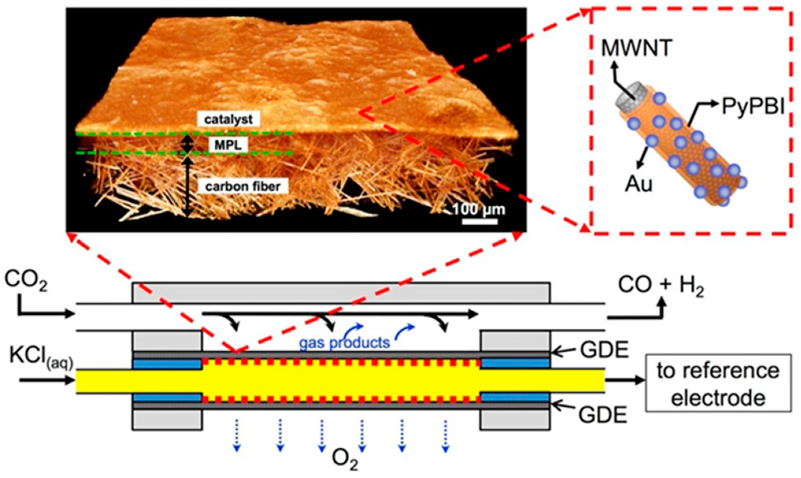
| MWNT/PyPBI | Au | Wet chemistry process with CNTs | 1.0 M KCl, CO, CD 160 mA cm−2, FE 60%, overpotential 1.78 V vs. Ag/AgCl | [181] | |
| MWNT/PyPBI | Au | Wet chemistry process with CNTs | 2.0 M KOH, CO, CD 158 mA cm−2, FE 49.4%, overpotential 0.94 V vs. SHE, 8 h | [122] | |
| MWNT on SS | SnOx | in situ or hydrothermal method | 0.1 M KHCO3, formate, CD 5 mA cm−2, FE 64%, overpotential 1.4 V vs. SCE, 20 h | [187] | |
| MWNT on carbon paper | SnO2 | Wet impregnation | 0.5 M NaHCO3, formate, CD 80 mA cm−2, FE 27.2%, overpotential 1.7 V vs. SCE | [188] | |
| CNT Aerogel | Sn | Wet chemistry + calcination in H2 | 0.5 M KHCO3, formate, CD 24 mA cm−2, FE 82.7%, overpotential 0.96 V vs. RHE, 5.6 h | [191] | |
| CNT | HNCM | Wet chemistry + pyrolysis | 0.1 M KHCO3, formate, CD 8 mA cm−2, FE 81%, overpotential 0.8 V vs. RHE, 36 h | [193] | |
| NCNT | Co0.75Ni0.25 | Electrospinning + pyrolysis | 0.5 M NaHCO3, CO, CD 13.4 mA cm−2, FE 85%, overpotential 0.9 V vs. RHE | [196] | |
| NCNT | Sn | Electrospinning + pyrolysis | 0.5 KHCO3, formate, CD 11 mA cm−2, FE 62%, overpotential 0.69 V vs. RHE | [165] | |
| CC | SnO2 | Hydrothermal reaction + calcination | 0.5 M NaHCO3, formate, CD 45 mA cm−2, FE 87.2%, overpotential 0.88 V vs. Ag/AgCl | [200] | |
| ACF | Metal complexes | Wet chemistry | 0.1 M KHCO3, CO, CD 70 mA cm−2, FE 70%, overpotential 1.5 V vs. SCE | [205] | |
| CuxO NW | Sn-CuxO | Anodizing, dehydration reduction, electroless deposition | 0.1 M KHCO3, CO, CD 4.5 mA cm−2, FE 90%, overpotential 0.69 V vs. RHE | [207] | |
| CNF | Cu-CeOx | Electrospinning + pyrolysis | 1.0 M KOH, CO, CD 100 mA cm−2, FE 59.2%, overpotential 0.60 V vs. RHE | [212] | |
| CNT | Cu-6.2%SnOx | Electrospinning + pyrolysis | 0.1 M KHCO3, CO, CD 11.3 mA cm−2, FE 89%, overpotential 0.99 V vs. RHE | [213] | |
| CNT | Cu-30.2%SnOx | Electrospinning + pyrolysis | 0.1 M KHCO3, formate, CD 4.0 mA cm−2, FE 77%, overpotential 0.99 V vs. RHE | [213] | |
| 2D Building Blocks | 3D graphene | N doped 3D-GNE | CVD | FE 85% at −0.47 V, 5 h for CO2RR into CO | [136] |
| 3D graphene | Iron porphyrin/graphene hydrogel (FePGH | Hydrothermal with ascorbic acid | FE 96.2% at −0.39V and i = 0.42A/cm2, 19 h for CO2RR into CO | [227] | |
| NGA (N doped 3D graphene) | MnO | Hydrothermal | FE of 86% at −0.82 (RHE), 10 h for CO2RR into CO | [228] | |
| N-doped MEGO | Ni-N-MEGO | Microwave exfoliated 3D rGO | FE of 92% at –0.7V, 21 h for CO2RR into CO | [229] | |
| 3D reduced GO | Pd0.5-In0.5/3D rGO | Chemical and hydrothermal | FE of 85.3% at −1.6V (Ag/AgCl) for CO2RR into CO | [106] | |
| 3D Building Blocks | Pt | Dual-templating approach | FE and yield for alcohol: 23.9% and 2.1 × 10⁻⁸ mol s−1 cm−2 at 51 mA cm−2, respectively. −2.05 V (vs. RHE) over 10 h | [241] | |
| Ag | Dealloy method | Overpotential <500 mV, FE 92% CO | [246] | ||
| Cu Foam | SnOx@Sn-Cu/Sn core-shell | Electrodeposition Technique | 406.7 +/− 14.4 mA cm−2 with C1 FE 98.0 +/− 0.9% at −0.70 V vs. RHE, 243.1 +/− 19.2 mA cm−2 with C1 FE 99.0 +/− 0.5% for 40 h at −0.55 V vs. RHE | [247] | |
| Carbon cloth | SnO2 | Hydrothermal method | 45 mA cm−2 at overpotential (−0.88 V), FE (87 +/− 2%), formate | [200] | |
| Graphene | SnO2 | Hydrothermal method | 10 mA cm−2, overpotential (−0.88 V) FE 93% for 18 h, formate | [197] | |
| CNT | RVC | CVD and EPD | 200 mA cm−2 FE 100%, acetate | [105] | |
| CNT | N-doped carbon | MOF | Formate, −0.9 V vs. RHE, FE 81% | [193] | |
| F-doped carbon | Template method | FE 88.3% for CO at −1.0 V vs. RHE at 37.5 mA·cm−2 for 12 h | [251] | ||
| PTFE | Cu | Sputtering method | 7m KOH for 150 h −0.55 V vs. RHE, FE for ethylene 70%. | [96] | |
| N doped carbon | Cu/CuO | MOF | Formate FE 70.5% at −0.68 V. 30 h of 4.4 mA cm−2 | [252] | |
| N-doped carbon | Ni | MOF | FE, CO over 71.9% at 10.48 mA cm−2 at overpotential −0.89 V. of 60 h | [253] | |
| CNT | Co | Electrospin | FE over 90% CO at 200 mA cm−2 | [254] | |
© 2020 by the authors. Licensee MDPI, Basel, Switzerland. This article is an open access article distributed under the terms and conditions of the Creative Commons Attribution (CC BY) license (http://creativecommons.org/licenses/by/4.0/).
Share and Cite
Hui, S.; Shaigan, N.; Neburchilov, V.; Zhang, L.; Malek, K.; Eikerling, M.; Luna, P.D. Three-Dimensional Cathodes for Electrochemical Reduction of CO2: From Macro- to Nano-Engineering. Nanomaterials 2020, 10, 1884. https://doi.org/10.3390/nano10091884
Hui S, Shaigan N, Neburchilov V, Zhang L, Malek K, Eikerling M, Luna PD. Three-Dimensional Cathodes for Electrochemical Reduction of CO2: From Macro- to Nano-Engineering. Nanomaterials. 2020; 10(9):1884. https://doi.org/10.3390/nano10091884
Chicago/Turabian StyleHui, Shiqiang (Rob), Nima Shaigan, Vladimir Neburchilov, Lei Zhang, Kourosh Malek, Michael Eikerling, and Phil De Luna. 2020. "Three-Dimensional Cathodes for Electrochemical Reduction of CO2: From Macro- to Nano-Engineering" Nanomaterials 10, no. 9: 1884. https://doi.org/10.3390/nano10091884