A Review about the Recent Advances in Selected NonThermal Plasma Assisted Solid–Gas Phase Chemical Processes


Abstract
:1. Introduction
1.1. Electron Beam
1.2. Corona Discharges
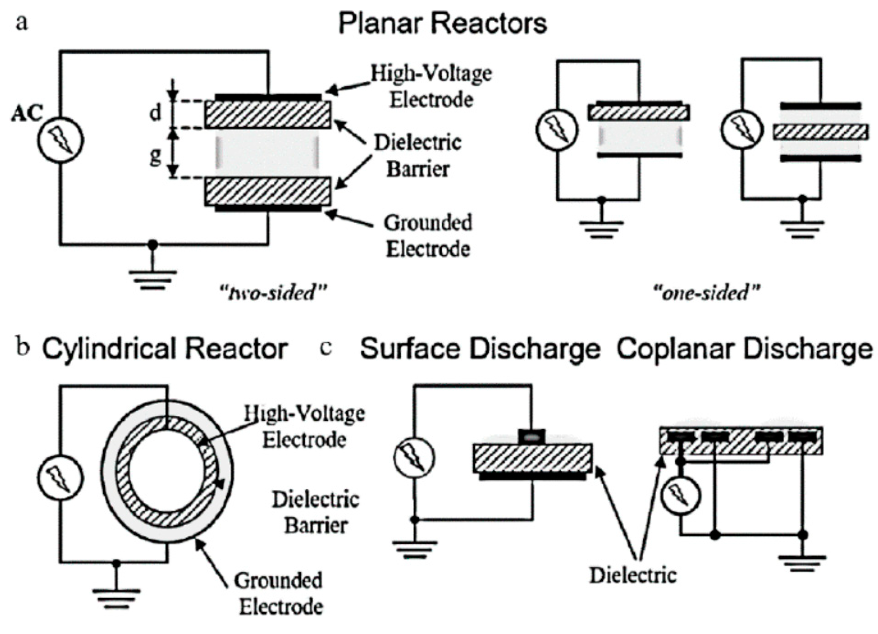
1.3. Dielectric Barrier Discharge
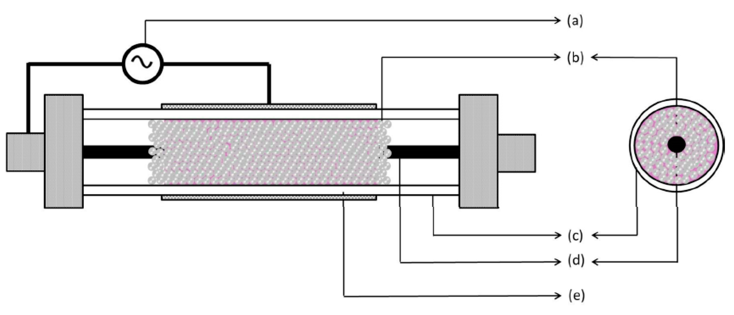
1.4. Dielectric Packed Bed Reactor
1.5. Surface Plasma Discharge
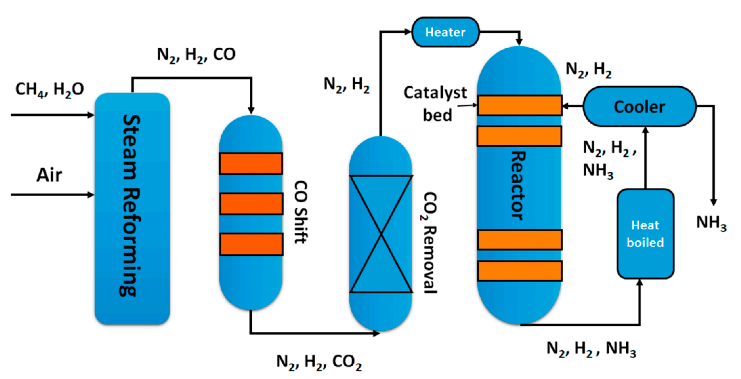
2. Ammonia Production via NTP Technology
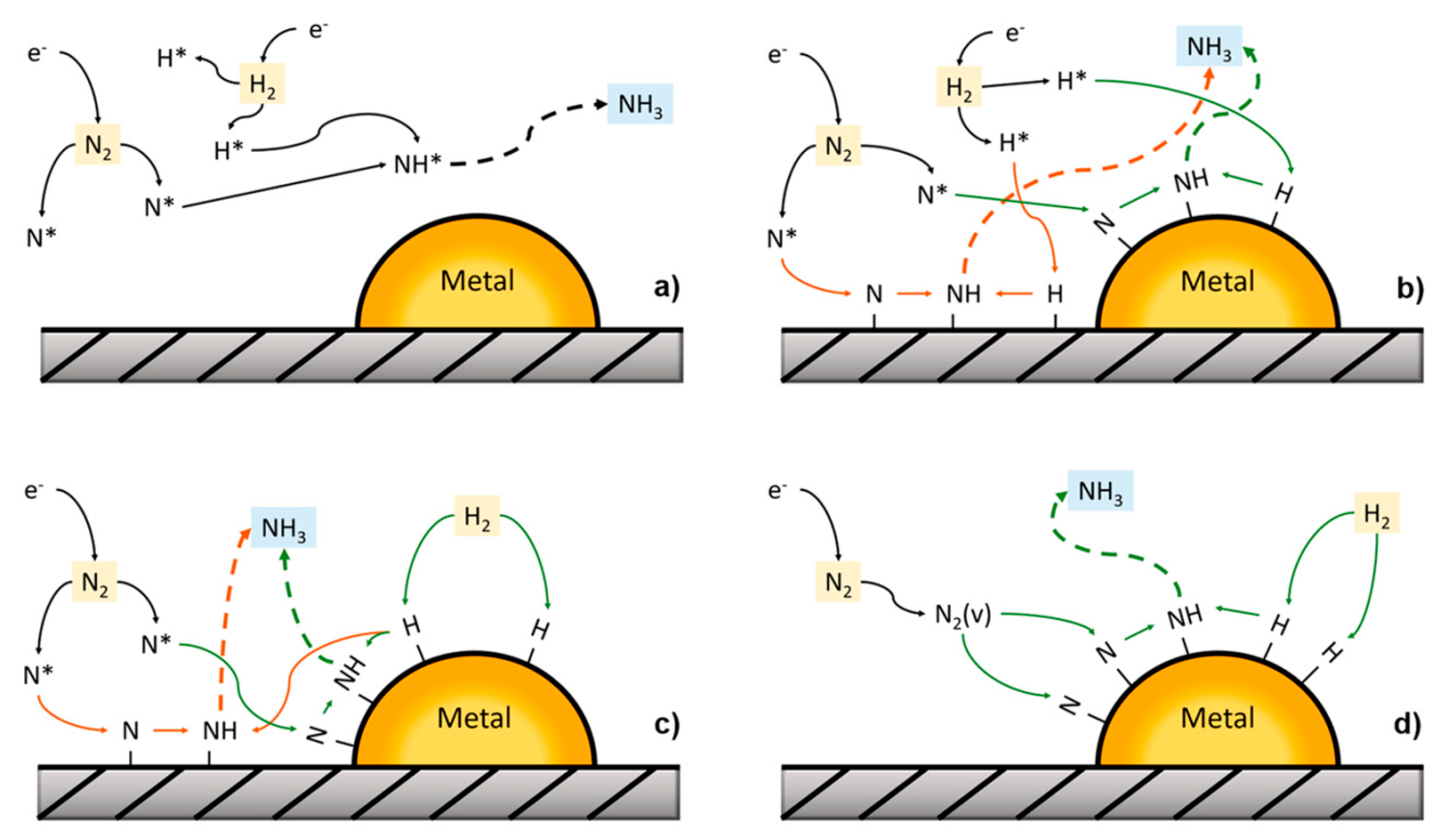
2.1. Mechanisms
2.2. Ru-Based Catalysts
2.3. Ni-Based Catalysts
2.4. Other Catalysts
2.5. Comparative Studies
2.6. Reactor Configurations
2.7. Urea Decomposition
Conclusions

| Selected Catalyst | Reaction Conditions | Efficiency (gNH3 kWh−1) | Reference |
|---|---|---|---|
| Ru/Si–MCM-41 | N2:H2 = 1:1; 5000 V | 1.7 | [23] |
| Ru/MCM-41 | N2:H2 = 3:1; 6000 V | 2.2 | [24] |
| Ru(2)–Mg(5)/γ-Al2O3 | N2:H2 = 4:1; T = 250 °C | 25.5 | [25] |
| Ni–MOF | N2:H2 = 1:4; T = 82.3 °C | 0.23 | [26] |
| PZT | N2:H2 = 3:1; 5000 V | 0.65 | [29] |
| DLC-coated Al2O3 | N2:H2 = 3:1; 17,500 V | 0.9 | [30] |
| Zeolite 5A | N2:H2 = 1:1 | 15.5 | [31] |
| Ni/Al2O3 | N2:H2 = 1:2; 24,000 V | 0.45 | [32] |
3. Catalytic SO2 Removal via NTP Technology
4. Catalytic H2S Removal via NTP Technology
Conclusions
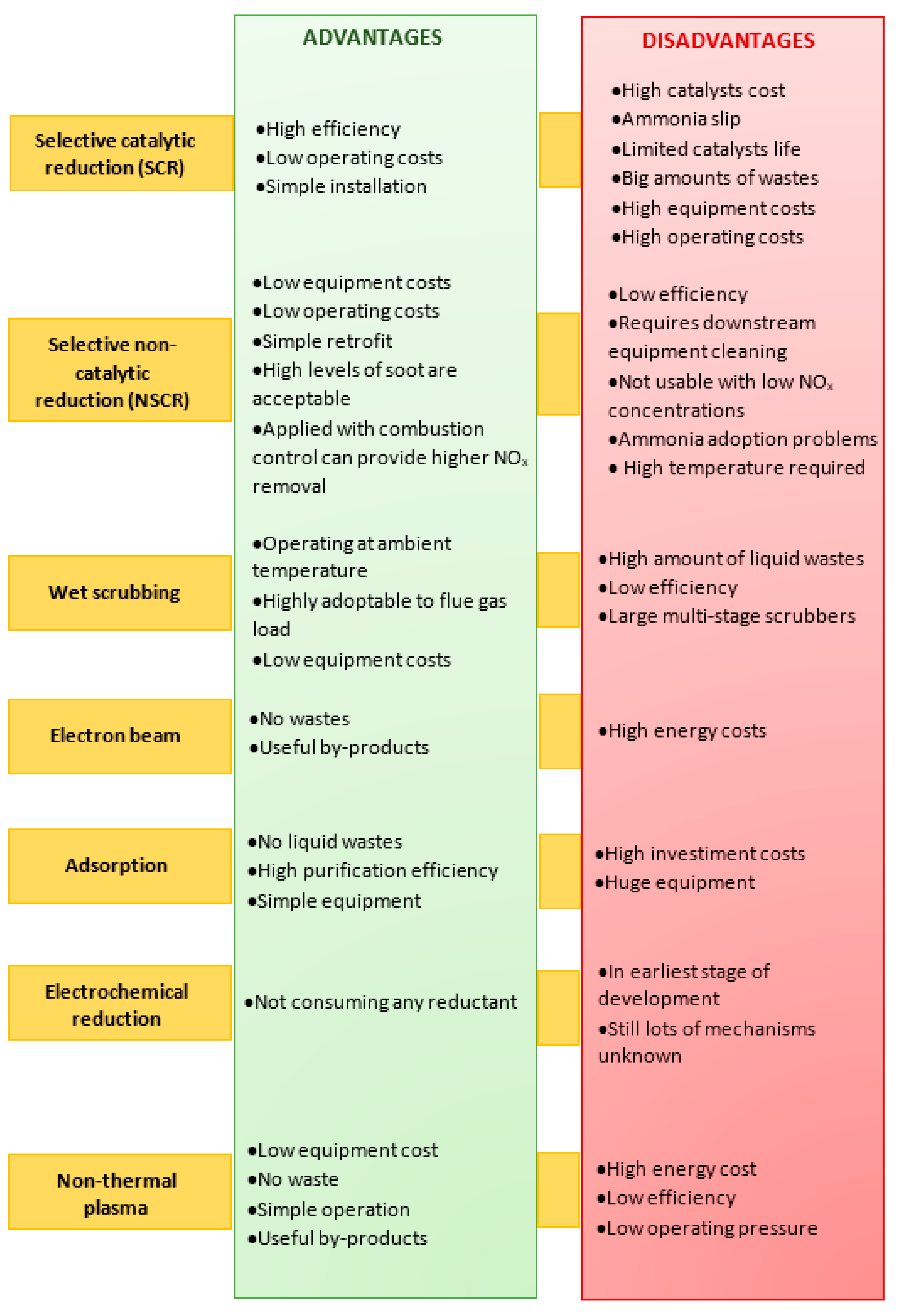
5. NOx Removal via NTP Technology
5.1. NOx Catalytic Removal via NTP Technology
5.2. NOx Non-Catalytic Removal via NTP Technology
- (i)
- In the case of no SO2 at the reactor inlet, the ozone injection was the 60% with respect to the NO concentration and a total NOx removal efficiency has been obtained, mainly attributed by the authors to the formation of trivalent N species (N2O3 and HNO2) and their fast absorption in NaOH;
- (ii)
- With a SO2 concentration of 1000 ppm, the ozone concentration has been increased to the 90% of the NO concentration to improve the NOx removal efficiency;
- (iii)
- With higher SO2 concentration, even higher NOx removal efficiencies were gained, because the SO2 scrubbing product, Na2SO3, improved the NO2 scrubbing.
Conclusions
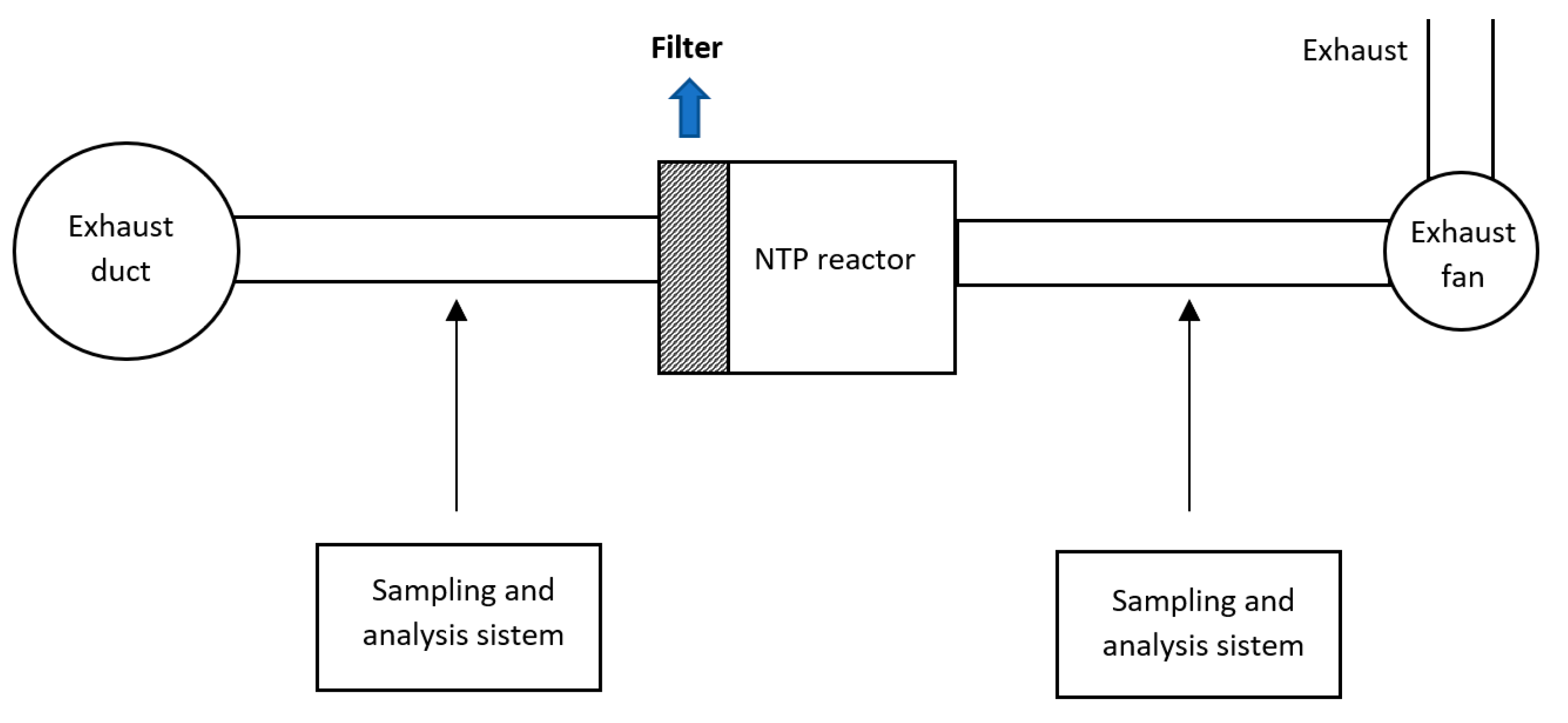
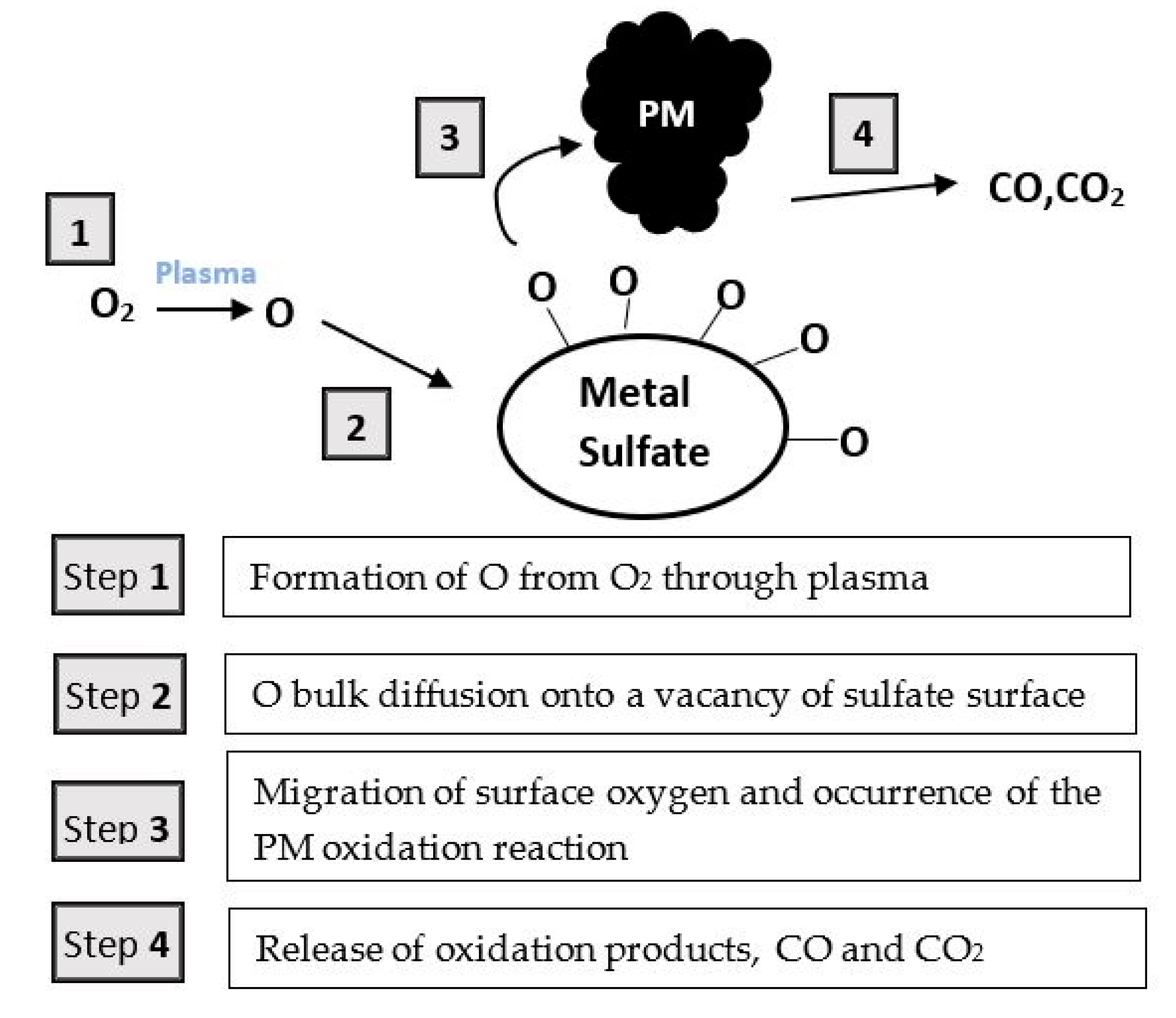
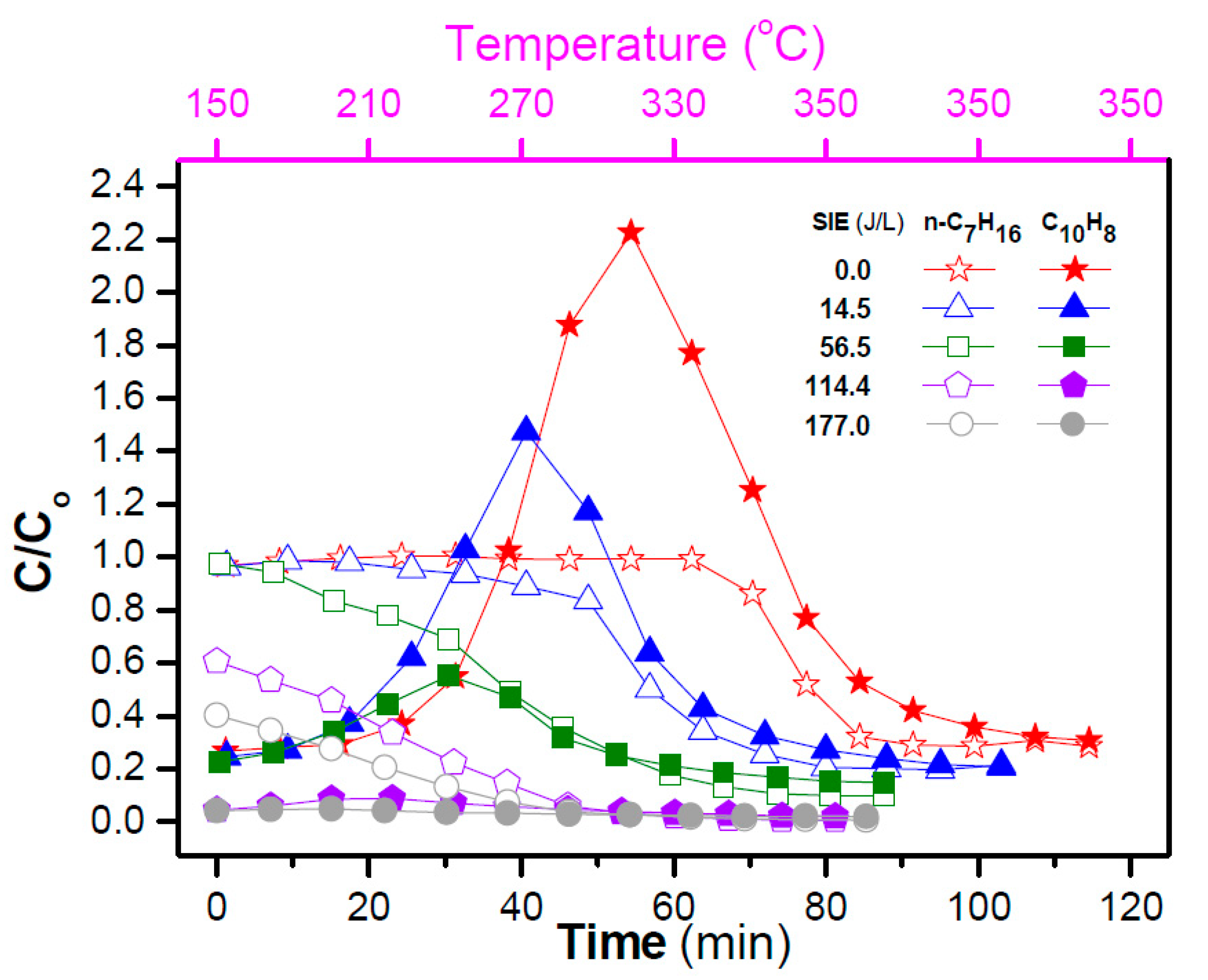
6. Soot Abatement via NTP Technology
Conclusions
7. CO2 Utilization
7.1. CO2 Reforming of Methane
7.1.1. Catalytic NTP-Assisted CO2 Reforming of Methane
7.1.2. Non Catalytic NTP-Assisted CO2 Reforming of Methane
Conclusions
7.2. CO2 Reforming of Methane
Conclusions
8. VOCs Abatement via NTP Technology
9. Conclusions
Funding
Conflicts of Interest
Acronyms
| AC | activated carbon |
| BET | Brunauer–Emmett–Teller |
| CCSU | carbon capture, storage and utilization |
| CMS | carbon molecular sieves |
| DBD | dielectric barrier discharge |
| DBDR | dielectric barrier discharge reactor |
| DDBD | double dielectric barrier discharge |
| DFT | density functional theory |
| DPF | diesel particulate filter |
| DRM | dry reforming of methane |
| EI | energy injection |
| GA | gliding arc |
| GD | glow discharge |
| GHSV | gas hourly space velocity |
| HC–SCR | hydrocarbon catalytic reduction |
| IPC | in-plasma catalysis |
| LNT | lean NOx trap |
| MOF | metal organic frameworks |
| MR | methane reforming |
| MW | microwave |
| NMOR | natural mordenite |
| NP | nanoparticles |
| NSR | NOx storage and reduction |
| NTP | non-thermal plasma |
| PCP | pulsed-corona plasma |
| PCVD | plasma chemical vapor deposition |
| PM | particulate matter |
| PPC | post-plasma catalysis |
| RF | radio frequency |
| RGA | rotating gliding arc |
| RPM | revolution per minute |
| SCR | selective catalytic reduction |
| SED | specific energy density |
| SEI | specific energy input |
| SEM | scanning electron microscopy |
| SNCR | selective noncatalytic reduction |
| SRE | soot-removal efficiency |
| TEM | transmission electron microscopy |
| TPD | temperature programmed desorption |
| VBD | volume barrier discharge |
| VOCs | volatile organic compounds |
| WSAC | walnut-shell activated carbon |
| XPS | X-ray photoelectron spectroscopy |
References
- Talebizadeh, P.; Babaie, M.; Brown, R.; Rahimzadeh, H.; Ristovski, Z.; Arai, M. The role of non-thermal plasma technique in NOx treatment: A review. Renew. Sustain. Energy Rev. 2014, 40, 886–901. [Google Scholar] [CrossRef] [Green Version]
- Chen, X.; Cheng, Y.; Li, T.; Cheng, Y. Characteristics and applications of plasma assisted chemical processes and reactors. Curr. Opin. Chem. Eng. 2017, 17, 68–77. [Google Scholar] [CrossRef]
- Kim, H.-H.; Teramoto, Y.; Ogata, A.; Takagi, H.; Nanba, T. Plasma Catalysis for Environmental Treatment and Energy Applications. Plasma Chem Plasma Process 2016, 36, 45–72. [Google Scholar] [CrossRef]
- Tyczkowski, J. Cold Plasma Produced Catalytic Materials. In Plasma Science and Technology-Progress in Physical States and Chemical Reactions; Tetsu, M., Ed.; InTechOpen: London, UK, 2016; Chapter 3. [Google Scholar]
- Lee, D.H.; Song, Y.-H.; Kim, K.-T.; Jo, S.; Kang, H. Current state and perspectives of plasma applications for catalyst regeneration. Catal. Today 2019, 337, 15–27. [Google Scholar] [CrossRef]
- Li, J.; Ma, C.; Zhu, S.; Yu, F.; Dai, B.; Yang, D. A Review of Recent Advances of Dielectric Barrier Discharge Plasma in Catalysis. Nanomaterials 2019, 9, 1428. [Google Scholar] [CrossRef] [Green Version]
- Lim, M.T.; Shah Zulkifli, A.Z.; Jayapalan, K.K.; Chin, O. Development of a dimensionless parameter for characterization of dielectric barrier discharge devices with respect to geometrical features. Plasma Sci. Technol. 2017, 19, 095402. [Google Scholar] [CrossRef]
- Wang, X.; Yang, Q.; Yao, C.; Zhang, X.; Sun, C. Dielectric Barrier Discharge Characteristics of Multineedle-to-Cylinder Configuration. Energies 2011, 4, 2133–2150. [Google Scholar] [CrossRef] [Green Version]
- Veerapandian, S.K.P.; Leys, C.; de Geyter, N.; Morent, R. Abatement of VOCs Using Packed Bed Non-Thermal Plasma Reactors: A Review. Catalysts 2017, 7, 113. [Google Scholar] [CrossRef]
- Bosch, C. Process of Producing Ammonia. U.S. Patent 990191A, 18 April 1911. [Google Scholar]
- Vu, M.-H.; Sakar, M.; Do, T.-O. Insights into the Recent Progress and Advanced Materials for Photocatalytic Nitrogen Fixation for Ammonia (NH3) Production. Catalysts 2018, 8, 621. [Google Scholar] [CrossRef] [Green Version]
- Hong, J.; Prawer, S.; Murphy, A.B. Plasma Catalysis as an Alternative Route for Ammonia Production: Status, Mechanisms, and Prospects for Progress. ACS Sustain. Chem. Eng. 2018, 6, 15–31. [Google Scholar] [CrossRef]
- Wang, K.; Smith, D.; Zheng, Y. Electron-driven heterogeneous catalytic synthesis of ammonia: Current states and perspective. Carbon Resour. Convers. 2018, 1, 2–31. [Google Scholar] [CrossRef]
- Peng, P.; Chen, P.; Schiappacasse, C.; Zhou, N.; Anderson, E.; Chen, D.; Liu, J.; Cheng, Y.; Hatzenbeller, R.; Addy, M.; et al. A review on the non-thermal plasma-assisted ammonia synthesis technologies. J. Clean. Prod. 2018, 177, 597–609. [Google Scholar] [CrossRef]
- Li, S.; Medrano, J.A.; Hessel, V.; Gallucci, F. Recent Progress of Plasma-Assisted Nitrogen Fixation Research: A Review. Processes 2018, 6, 248. [Google Scholar] [CrossRef] [Green Version]
- Bogaerts, A.; Neyts, E.C. Plasma Technology: An Emerging Technology for Energy Storage. ACS Energy Lett. 2018, 3, 1013–1027. [Google Scholar] [CrossRef] [Green Version]
- Gorbanev, Y.; Vervloessem, E.; Nikiforov, A.; Bogaerts, A. Nitrogen Fixation with Water Vapor by Nonequilibrium Plasma: Toward Sustainable Ammonia Production. ACS Sustain. Chem. Eng. 2020, 8, 2996–3004. [Google Scholar] [CrossRef]
- Rouwenhorst, K.H.R.; Kim, H.-H.; Lefferts, L. Vibrationally Excited Activation of N2 in Plasma-Enhanced Catalytic Ammonia Synthesis: A Kinetic Analysis. ACS Sustain. Chem. Eng. 2019, 7, 17515–17522. [Google Scholar] [CrossRef] [Green Version]
- Hagen, S.; Barfod, R.; Fehrmann, R.; Jacobsen, C.J.H.; Teunissen, H.T.; Chorkendorff, I. Ammonia synthesis with barium-promoted iron-cobalt alloys supported on carbon. J. Catal. 2003, 214, 327–335. [Google Scholar] [CrossRef]
- Mizushima, T.; Matsumoto, K.; Ohkita, H.; Kakuta, N. Catalytic Effects of Metal-Loaded Membrane-like Alumina Tubes on Ammonia Synthesis in Atmospheric Pressure Plasma by Dielectric Barrier Discharge. Plasma Chem. Plasma Process 2007, 27, 1–11. [Google Scholar] [CrossRef]
- Mehta, P.; Barboun, P.; Herrera, F.A.; Kim, J.; Rumbach, P.; Go, D.B.; Hicks, J.C.; Schneider, W.F. Overcoming Ammonia Synthesis Scaling Relations with Plasma-Enabled Catalysis. Nat. Catal. 2018, 1, 269–275. [Google Scholar] [CrossRef]
- Van Helden, J.H.; van den Oever, P.J.; Kessels, W.M.M.; van de Sanden, M.C.M.; Schram, D.C.; Engeln, R. Production Mechanisms of NH and NH2 Radicals in N2-H2 Plasmas. J. Phys. Chem. A 2007, 111, 11460–11472. [Google Scholar] [CrossRef]
- Peng, P.; Cheng, Y.; Hatzenbeller, R.; Addy, M.; Zhou, N.; Schiappacasse, C.; Chen, D.; Zhang, Y.; Anderson, E.; Liu, Y.; et al. Ru-based multifunctional mesoporous catalyst for low-pressure and non-thermal plasma synthesis of ammonia. Int. J. Hydrogen Energy 2017, 42, 19056–19066. [Google Scholar] [CrossRef]
- Peng, P.; Li, Y.; Cheng, Y.; Deng, S.; Chen, P.; Ruan, R. Atmospheric Pressure Ammonia Synthesis Using Non-thermal Plasma Assisted Catalysis. Plasma Chem. Plasma Process. 2016, 36, 1201–1210. [Google Scholar] [CrossRef]
- Kim, H.-H.; Teramoto, Y.; Ogata, A.; Takagi, H.; Nanba, T. Atmospheric-pressure nonthermal plasma synthesis of ammonia over ruthenium catalysts. Plasma Process. Polym. 2017, 14, 1600157. [Google Scholar] [CrossRef]
- Shah, J.; Wu, T.; Lucero, J.; Carreon, M.A.; Carreon, M.L. Nonthermal Plasma Synthesis of Ammonia over Ni-MOF-74. ACS Sustain. Chem. Eng. 2019, 7, 377–383. [Google Scholar] [CrossRef]
- Akay, G.; Zhang, K. Process Intensification in Ammonia Synthesis Using Novel Coassembled Supported Microporous Catalysts Promoted by Nonthermal Plasma. Ind. Eng. Chem. Res. 2017, 56, 457–468. [Google Scholar] [CrossRef] [Green Version]
- De Castro, A.; Alegre, D.; Tabarés, F.L. Ammonia formation in N2/H2 plasmas on ITER-relevant plasma facing materials: Surface temperature and N2 plasma content effects. J. Nucl. Mater. 2015, 463, 676–679. [Google Scholar] [CrossRef]
- Gómez-Ramírez, A.; Montoro-Damas, A.M.; Cotrino, J.; Lambert, R.M.; González-Elipe, A.R. About the enhancement of chemical yield during the atmospheric plasma synthesis of ammonia in a ferroelectric packed bed reactor. Plasma Process. Polym. 2016, 14, 1600081. [Google Scholar] [CrossRef]
- Hong, J.; Aramesh, M.; Shimoni, O.; Seo, D.H.; Yick, S.; Greig, A.; Charles, C.; Prawer, S.; Murphy, A.B. Plasma Catalytic Synthesis of Ammonia Using Functionalized-Carbon Coatings in an Atmospheric-Pressure Non-equilibrium Discharge. Plasma Chem. Plasma Process. 2016, 36, 917–940. [Google Scholar] [CrossRef]
- Shah, J.R.; Gorky, F.; Lucero, J.; Carreon, M.A.; Carreon, M.L. Ammonia Synthesis via Atmospheric Plasma Catalysis: Zeolite 5A, a Case of Study. Ind. Eng. Chem. Res. 2020, 59, 5167–5176. [Google Scholar] [CrossRef]
- Wang, Y.; Craven, M.; Yu, X.; Ding, J.; Bryant, P.; Huang, J.; Tu, X. Plasma-Enhanced Catalytic Synthesis of Ammonia over a Ni/Al2O3 Catalyst at Near-Room Temperature: Insights into the Importance of the Catalyst Surface on the Reaction Mechanism. ACS Catal. 2019, 9, 10780–10793. [Google Scholar] [CrossRef] [Green Version]
- Barboun, P.; Mehta, P.; Herrera, F.A.; Go, D.B.; Schneider, W.F.; Hicks, J.C. Distinguishing Plasma Contributions to Catalyst Performance in Plasma-Assisted Ammonia Synthesis. ACS Sustain. Chem. Eng. 2019, 7, 8621–8630. [Google Scholar] [CrossRef]
- Iwamoto, M.; Akiyama, M.; Aihara, K.; Deguchi, T. Ammonia Synthesis on Wool-Like Au, Pt, Pd, Ag, or Cu Electrode Catalysts in Nonthermal Atmospheric-Pressure Plasma of N2 and H2. ACS Catal. 2017, 7, 6924–6929. [Google Scholar] [CrossRef]
- Herrera, F.A.; Brown, G.H.; Barboun, P.; Turan, N.; Mehta, P.; Schneider, W.F.; Hicks, J.C.; Go, D.B. The impact of transition metal catalysts on macroscopic dielectric barrier discharge (DBD) characteristics in an ammonia synthesis plasma catalysis reactor. J. Phys. D Appl. Phys. 2019, 52, 224002. [Google Scholar] [CrossRef]
- Akay, G. Sustainable Ammonia and Advanced Symbiotic Fertilizer Production Using Catalytic Multi-Reaction-Zone Reactors with Nonthermal Plasma and Simultaneous Reactive Separation. ACS Sustain. Chem. Eng. 2017, 5, 11588–11606. [Google Scholar] [CrossRef]
- Sarafraz, M.M.; Tran, N.N.; Pourali, N.; Rebrov, E.V.; Hessel, V. Thermodynamic potential of a novel plasma-assisted sustainable process for co-production of ammonia and hydrogen with liquid metals. Energy Convers. Manage. 2020, 210, 112709. [Google Scholar] [CrossRef]
- Fan, X.; Li, J.; Qiu, D.; Zhu, T. Production of ammonia from plasma-catalytic decomposition of urea: Effects of carrier gas composition. J. Environ. Sci. 2018, 66, 94–103. [Google Scholar] [CrossRef]
- Chen, Z.; Mathur, V.K. Nonthermal Plasma for Gaseous Pollution Control. Ind. Eng. Chem. Res. 2002, 41, 2082–2089. [Google Scholar] [CrossRef]
- Xu, F.; Luo, Z.; Cao, W.; Wang, P.; Wei, B.; Gao, X.; Fang, M.; Cen, K. Simultaneous oxidation of NO, SO2 and Hg0 from flue gas by pulsed corona discharge. J. Environ. Sci. 2009, 21, 328–332. [Google Scholar] [CrossRef]
- Cui, S.; Hao, R.; Fu, D. An integrated system of dielectric barrier discharge combined with wet electrostatic precipitator for simultaneous removal of NO and SO2: Key factors assessments, products analysis and mechanism. Fuel 2018, 221, 12–20. [Google Scholar] [CrossRef]
- Yu, Q.; Yang, H.-M.; Zeng, K.-S.; Zhang, Z.-W.; Yu, G. Simultaneous removal of NO and SO2 from dry gas stream using non-thermal plasma. J. Environ. Sci. 2007, 19, 1393–1397. [Google Scholar] [CrossRef]
- Ma, S.; Zhao, Y.; Yang, J.; Zhang, S.; Zhang, J.; Zheng, C. Research progress of pollutants removal from coal-fired flue gas using non-thermal plasma. Renew. Sustain. Energy Rev. 2017, 67, 791–810. [Google Scholar] [CrossRef]
- Kim, H.; Mizuno, A.; Sakaguchi, Y.; Lu, G.; Sadakata, M. Development of a New Dry-Desulfurization Process by a Non-Thermal Plasma Hybrid Reactor. Energy Fuels 2002, 16, 803–808. [Google Scholar] [CrossRef]
- Kwon, Y.K.; Han, D.H. Microwave Effect in the Simultaneous Removal of NOx and SO2 under Electron Beam Irradiation and Kinetic Investigation of NOx Removal Rate. Ind. Eng. Chem. Res. 2010, 49, 8147–8156. [Google Scholar] [CrossRef]
- Panomsuwan, G.; Rujiravanit, R.; Ueno, T.; Saito, N. Non-thermal plasma technology for abatement of pollutant emission from marine diesel engine. J. Korean Soc. Mar. Eng. 2016, 40, 929–934. [Google Scholar] [CrossRef]
- Ighigeanu, D.; Martin, D.; Zissulescu, E.; Macarie, R.; Oproiu, C.; Cirstea, E.; Iovu, H.; Calinescu, I.; Iacob, N. SO2 and NOx removal by electron beam and electrical discharge induced non-thermal plasmas. Vacuum 2005, 77, 493–500. [Google Scholar] [CrossRef]
- Cui, S.; Zhong, Z.; Liao, Y.; Qi, L.; Fu, D. Simultaneous Removal of NO and SO2 via an Integrated System of Nonthermal Plasma Combined with Catalytic Oxidation and Wet Electrostatic Precipitator. Energy Fuels 2019, 33, 10078–10089. [Google Scholar] [CrossRef]
- Cui, S.; Hao, R.; Fu, D. Integrated method of non-thermal plasma combined with catalytical oxidation for simultaneous removal of SO2 and NO. Fuel 2019, 246, 365–374. [Google Scholar] [CrossRef]
- Hamzehlouyan, T.; Sampara, C.S.; Li, J.; Kumar, A.; Epling, W.S. Kinetic study of adsorption and desorption of SO2 over γ-Al2O3 and Pt/γ-Al2O3. Appl. Catal. B Environ. 2016, 181, 587–598. [Google Scholar] [CrossRef]
- AlQahtani, M.S.; Knecht, S.D.; Wang, X.; Bilén, S.G.; Song, C. One-Step Low-Temperature Reduction of Sulfur Dioxide to Elemental Sulfur by Plasma-Enhanced Catalysis. ACS Catalysis 2020, 10, 5272–5277. [Google Scholar] [CrossRef]
- Nasonova, A.; Kim, D.-J.; Kim, K.-S. Analysis of SO2 Removal and Ammonium Sulfate Particle Growth in Dielectric Barrier Discharge−Photocatalyst Hybrid Process. Ind. Eng. Chem. Res. 2010, 49, 8821–8825. [Google Scholar] [CrossRef]
- Nasonova, A.; Pham, H.C.; Kim, D.-J.; Kim, K.-S. NO and SO2 removal in non-thermal plasma reactor packed with glass beads-TiO2 thin film coated by PCVD process. Chem. Eng. J. 2010, 156, 557–561. [Google Scholar] [CrossRef]
- Pham, H.-C.; Kim, K.-S. Effect of TiO2 Thin Film Thickness on NO and SO2 Removals by Dielectric Barrier Discharge-Photocatalyst Hybrid Process. Ind. Eng. Chem. Res. 2013, 52, 5296–5301. [Google Scholar] [CrossRef]
- Nasonova, A.; Kim, K.-S. Effects of TiO2 coating on zeolite particles for NO and SO2 removal by dielectric barrier discharge process. Catal. Today 2013, 211, 90–95. [Google Scholar] [CrossRef]
- Wang, J.; Yi, H.; Tang, X.; Zhao, S.; Gao, F. Simultaneous removal of SO2 and NOx by catalytic adsorption using γ-Al2O3 under the irradiation of non-thermal plasma: Competitiveness, kinetic, and equilibrium. Chem. Eng. J. 2020, 384, 123334. [Google Scholar] [CrossRef]
- Hong, L.; Chen, D.; Yang, M.; Yin, L.; Wang, D.; Wang, L. Interaction between NO and SO2 removal processes in a pulsed corona discharge plasma (PCDP) reactor and the mechanism. Chem. Eng. J. 2019, 359, 1130–1138. [Google Scholar] [CrossRef]
- Sassi, M.; Amira, N. Chemical reactor network modeling of a microwave plasma thermal decomposition of H2S into hydrogen and sulfur. Int. J. Hydrogen Energy 2012, 37, 10010–10019. [Google Scholar] [CrossRef]
- Liang, W.-J.; Fang, H.-P.; Li, J.; Zheng, F.; Li, J.-X.; Jin, Y.-Q. Performance of non-thermal DBD plasma reactor during the removal of hydrogen sulfide. J. Electrost. 2011, 69, 206–213. [Google Scholar] [CrossRef]
- Lu, S.; Chen, L.; Huang, Q.; Yang, L.; Du, C.; Li, X.; Yan, J. Decomposition of ammonia and hydrogen sulfide in simulated sludge drying waste gas by a novel non-thermal plasma. Chemosphere 2014, 117, 781–785. [Google Scholar] [CrossRef]
- Reddy, E.L.; Biju, V.M.; Subrahmanyam, C. Production of hydrogen from hydrogen sulfide assisted by dielectric barrier discharge. Int. J. Hydrogen Energy 2012, 37, 2204–2209. [Google Scholar] [CrossRef]
- Huang, L.; Xia, L.; Dong, W.; Hou, H. Energy efficiency in hydrogen sulfide removal by non-thermal plasma photolysis technique at atmospheric pressure. Chem. Eng. J. 2013, 228, 1066–1073. [Google Scholar] [CrossRef]
- De Crisci, A.G.; Moniri, A.; Xu, Y. Hydrogen from hydrogen sulfide: Towards a more sustainable hydrogen economy. Int. J. Hydrogen Energy 2019, 44, 1299–1327. [Google Scholar] [CrossRef]
- Nunnally, T.; Gutsol, K.; Rabinovich, A.; Fridman, A.; Starikovsky, A.; Gutsol, A.; Potter, R.W. Dissociation of H2S in non-equilibrium gliding arc “tornado” discharge. Int. J. Hydrogen Energy 2009, 34, 7618–7625. [Google Scholar] [CrossRef]
- Mousavi, S.M.A.; Piavis, W.; Turn, S. Reforming of biogas using a non-thermal, gliding-arc, plasma in reverse vortex flow and fate of hydrogen sulfide contaminants. Fuel Process. Technol. 2019, 193, 378–391. [Google Scholar] [CrossRef]
- Zhao, L.; Wang, Y.; Li, X.; Wang, A.; Song, C.; Hu, Y. Hydrogen production via decomposition of hydrogen sulfide by synergy of non-thermal plasma and semiconductor catalysis. Int. J. Hydrogen Energy 2013, 38, 14415–14423. [Google Scholar] [CrossRef]
- Zhao, L.; Wang, Y.; Jin, L.; Qin, M.; Li, X.; Wang, A.; Song, C.; Hu, Y. Decomposition of hydrogen sulfide in non-thermal plasma aided by supported CdS and ZnS semiconductors. Green Chem. 2013, 15, 1509–1513. [Google Scholar] [CrossRef]
- Wang, Y.; Zhao, L.; Sun, Z.; Li, X.; Wang, A.; Song, C.; Hu, Y. Decomposition of hydrogen sulfide in non-thermal plasma aided by supported ZnxCd1-xS solid solutions. Int. J. Plasma Environ. Sci. Technol. 2014, 8, 136–142. [Google Scholar] [CrossRef]
- Zhao, L.; Wang, Y.; Wang, A.; Li, X.; Song, C.; Hu, Y. Cr–doped ZnS semiconductor catalyst with high catalytic activity for hydrogen production from hydrogen sulfide in non-thermal plasma. Catalysis Today 2019, 337, 83–89. [Google Scholar] [CrossRef]
- Zhao, L.; Liu, X.; Mu, X.; Li, Y.; Fang, K. Highly selective conversion of H2S–CO2 to syngas by combination of non-thermal plasma and MoS2/Al2O3. J. CO2 Util. 2020, 37, 45–54. [Google Scholar] [CrossRef]
- Linga Reddy, E.; Karuppiah, J.; Renken, A.; Kiwi-Minsker, L.; Subrahmanyam, C. Kinetics of the Decomposition of Hydrogen Sulfide in a Dielectric Barrier Discharge Reactor. Chem. Eng. Technol. 2012, 35, 2030–2034. [Google Scholar] [CrossRef]
- Ning, P.; Liu, S.; Wang, C.; Li, K.; Sun, X.; Tang, L.; Liu, G. Adsorption-oxidation of hydrogen sulfide on Fe/walnut-shell activated carbon surface modified by NH3-plasma. J. Environ. Sci. 2018, 64, 216–226. [Google Scholar] [CrossRef]
- Li, K.; Liu, S.; Song, X.; Wang, C.; Ning, P.; Fan, M.; Sun, X. Catalytic Oxidation of Hydrogen Sulfide on Fe/WSAC Catalyst Surface Modification via NH3-NTP: Influence of Gas Gap and Dielectric Thickness. Ind. Eng. Chem. Res. 2018, 57, 2873–2881. [Google Scholar] [CrossRef]
- Xuan, K.; Zhu, X.; Cai, Y.; Tu, X. Plasma Oxidation of H2S over Non-stoichiometric LaxMnO3 Perovskite Catalysts in a Dielectric Barrier Discharge Reactor. Catalysts 2018, 8, 317. [Google Scholar] [CrossRef] [Green Version]
- Dang, X.; Huang, J.; Kang, L.; Wu, T.; Zhang, Q. Research on Decomposition of Hydrogen Sulfide Using Nonthermal Plasma with Metal Oxide Catalysis. Energy Procedia 2012, 16, 856–862. [Google Scholar] [CrossRef] [Green Version]
- Liang, C.; Cai, Y.; Li, K.; Luo, Y.; Qian, Z.; Chu, G.W.; Chen, J.F. Using dielectric barrier discharge and rotating packed bed reactor for NOx removal. Sep. Purif. Technol. 2020, 235, 116141. [Google Scholar] [CrossRef]
- Gholami, F.; Tomas, M.; Gholami, Z.; Vakili, M. Technologies for the nitrogen oxides reduction from flue gas: A review. Sci. Total Environ. 2020, 714, 136712. [Google Scholar] [CrossRef] [PubMed]
- Mladenovi, M.; Paprika, M.; Marinkovi, A. Denitrification techniques for biomass combustion. Renew. Sustain. Energy Rev. 2018, 82, 3350–3364. [Google Scholar] [CrossRef]
- Wang, Z.; Kuang, H.; Zhang, J.; Chu, L.; Ji, Y. Nitrogen oxide removal by non-thermal plasma for marine diesel engines. RSC Adv. 2019, 9, 5402–5416. [Google Scholar] [CrossRef] [Green Version]
- Stere, C.E.; Adress, W.; Burch, R.; Chansai, S.; Goguet, A.; Graham, W.G.; de Rosa, F.; Palma, V.; Hardacre, C. Ambient temperature hydrocarbon selective catalytic reduction of NOx using atmospheric pressure nonthermal plasma activation of a Ag/Al2O3 catalyst. ACS Catal. 2014, 4, 666–673. [Google Scholar] [CrossRef] [Green Version]
- Nguyen, D.B.; Nguyen, V.T.; Heo, I.J.; Mok, Y.S. Removal of NOx by selective catalytic reduction coupled with plasma under temperature fluctuation condition. J. Ind. Eng. Chem. 2019, 72, 400–407. [Google Scholar] [CrossRef]
- Wang, H.; Cao, Y.; Chen, Z.; Yu, Q.; Wu, S. High-efficiency removal of NOx over natural mordenite using an enhanced plasma-catalytic process at ambient temperature. Fuel 2018, 224, 323–330. [Google Scholar] [CrossRef]
- Zhang, Z.S.; Crocker, M.; Chen, B.B.; Wang, X.K.; Bai, Z.F.; Shi, C. Non-thermal plasma-assisted NOx storage and reduction over cobalt-containing LNT catalysts. Catal. Today 2015, 258, 386–395. [Google Scholar] [CrossRef] [Green Version]
- Zhang, Z.S.; Crocker, M.; Chen, B.B.; Bai, Z.F.; Wang, X.K.; Shi, C. Pt-free, non-thermal plasma-assisted NOx storage and reduction over M/Ba/Al2O3 (M = Mn, Fe, Co, Ni, Cu) catalysts. Catal. Today 2015, 256, 115–123. [Google Scholar] [CrossRef] [Green Version]
- Zhang, Z.S.; Crocker, M.; Yu, L.M.; Wang, X.K.; Bai, Z.F.; Shi, C. Non-thermal plasma assisted NOx storage and reduction over a cobalt-containing Pd catalyst using H2 and/or CO as reductants. Catal. Today 2015, 258, 175–182. [Google Scholar] [CrossRef] [Green Version]
- Bai, Z.; Zhang, Z.; Chen, B.; Zhao, Q.; Crocker, M.; Shi, C. Non-thermal plasma enhanced NSR performance over Pt/M/Ba/Al2O3 (M = Mn, Co, Cu) catalysts. Chem. Eng. J. 2017, 314, 688–699. [Google Scholar] [CrossRef] [Green Version]
- Yu, Q.; Wang, H.; Liu, T.; Xiao, L.; Jiang, X.; Zheng, X. High-efficiency removal of NOx using a combined adsorption-discharge plasma catalytic process. Environ. Sci. Technol. 2012, 46, 2337–2344. [Google Scholar] [CrossRef] [PubMed]
- Li, D.; Tang, X.; Yi, H.; Ma, D.; Gao, F. NOx Removal over Modified Carbon Molecular Sieve Catalysts Using a Combined Adsorption-Discharge Plasma Catalytic Process. Ind. Eng. Chem. Res. 2015, 54, 9097–9103. [Google Scholar] [CrossRef]
- Pan, H.; Guo, Y.; Jian, Y.; He, C. Synergistic Effect of Non-thermal Plasma on NOx Reduction by CH4 over an In/H-BEA Catalyst at Low Temperatures. Energy Fuel 2015, 29, 5282–5289. [Google Scholar] [CrossRef]
- Kim, G.T.; Seo, B.H.; Lee, W.J.; Park, J.; Kim, M.K.; Lee, S.M. Effects of applying non-thermal plasma on combustion stability and emissions of NOx and CO in a model gas turbine combustor. Fuel 2017, 194, 321–328. [Google Scholar] [CrossRef]
- Paulauskas, R.; Jogi, I.; Striugas, N.; Martuzevičius, D.; Erme, K.; Raud, J.; Tichonovas, M. Application of non-thermal plasma for NOx reduction in the flue gases. Energies 2019, 12, 3955. [Google Scholar] [CrossRef] [Green Version]
- Hashim, S.A.; Samsudin, F.N.D.b.; Wong, C.S.; Bakar, A.K.; Yap, S.L.; Zin, M.M.F. Non-thermal plasma for air and water remediation. Arch. Biochem. Biophys. 2016, 605, 34–40. [Google Scholar] [CrossRef]
- Guo, X.; Xu, Y.; Chen, M.; Du, D. Study on the Performance of NTP with Wood Fiber in NO Removal. Plasma Chem. Plasma Process. 2020, 40, 921–936. [Google Scholar] [CrossRef]
- Wang, T.; Sun, B. Effect of temperature and relative humidity on NOX removal by dielectric barrier discharge with acetylene. Fuel Process. Technol. 2016, 144, 109–114. [Google Scholar] [CrossRef]
- Adnan, Z.; Mir, S.; Habib, M. Exhaust gases depletion using non-thermal plasma (NTP). Atmos. Pollut. Res. 2017, 8, 338–343. [Google Scholar] [CrossRef]
- Yoon, H.J.; Park, H.W.; Park, D.W. Simultaneous Oxidation and Absorption of NOx and SO2 in an Integrated O3 Oxidation/Wet Atomizing System. Energy Fuel 2016, 30, 3289–3297. [Google Scholar] [CrossRef]
- Kang, M.S.; Shin, J.; Yu, T.U.; Hwang, J. Simultaneous removal of gaseous NOx and SO2 by gas-phase oxidation with ozone and wet scrubbing with sodium hydroxide. Chem. Eng. J. 2020, 381, 122601. [Google Scholar] [CrossRef]
- Rossomando, B.; Arsie, I.; Meloni, E.; Palma, V.; Pianese, C. Experimental Test on the Feasibility of Passive Regeneration in a Catalytic DPF at the Exhaust of a Light-Duty Diesel Engine; SAE Technical Paper, No. 2019-24-0045; SAE International: Warrendale, PA, USA, 2019. [Google Scholar] [CrossRef]
- Palma, V.; Barba, D.; Cortese, M.; Martino, M.; Renda, S.; Meloni, E. Microwaves and heterogeneous catalysis: A review on selected catalytic processes. Catalysts 2020, 10, 246. [Google Scholar] [CrossRef] [Green Version]
- Palma, V.; Meloni, E. Microwave assisted regeneration of a catalytic diesel soot trap. Fuel 2016, 181, 421–429. [Google Scholar] [CrossRef]
- Rossomando, B.; Arsie, I.; Meloni, E.; Palma, V.; Pianese, C. Experimental Testing of a Low Temperature Regenerating Catalytic DPF at the Exhaust of a Light-Duty Diesel Engine; SAE Technical Paper, No. 2018-01-0351; SAE International: Warrendale, PA, USA, 2018. [Google Scholar] [CrossRef]
- Ranji-Burachaloo, H.; Masoomi-Godarzi, S.; Khodadadi, A.A.; Mortazavi, Y. Synergetic effects of plasma and metal oxide catalysts on diesel soot oxidation. Appl. Catal. B Environ. 2016, 182, 74–84. [Google Scholar] [CrossRef]
- Thomas, S.E.; Martin, A.R.; Raybone, D.; Shawcross, J.T.; Ng, K.L.; Beech, P.; Whitehead, J.C. Non Thermal Plasma Aftertreatment of Particulates—Theoretical Limits and Impact on Reactor Design; SAE Technical Paper; SAE International: Warrendale, PA, USA, 2000; Volume 109, pp. 1594–1606. [Google Scholar] [CrossRef]
- Yao, S.; Shen, X.; Zhang, X.; Han, J.; Wu, Z.; Tang, X.; Lu, H.; Jiang, B. Sustainable removal of particulate matter from diesel engine exhaust at low temperature using a plasma-catalytic method. Chem. Eng. J. 2017, 327, 343–350. [Google Scholar] [CrossRef]
- Zhang, M.; Jin, B.; Liu, Y.; Liu, W.; Weng, D.; Wu, X.; Liu, S. Ozone activated Ag/CeO2 catalysts for soot combustion: The surface and structural influences. Chem. Eng. J. 2019, 375, 121961. [Google Scholar] [CrossRef]
- Yao, S.; Shen, X.; Lu, H.; Ni, D.; Tang, X.; Wu, Z.; Han, J.; Zhang, X. Metal sulfates enhanced plasma oxidization of diesel particulate matter. IEEE Trans. Plasma Sci. 2017, 45, 2084–2087. [Google Scholar] [CrossRef]
- Nguyen, V.T.; Nguyen, D.B.; Heo, I.; Mok, Y.S. Plasma-assisted selective catalytic reduction for low-temperature removal of NOx and soot simulant. Catalysts 2019, 9, 853. [Google Scholar] [CrossRef] [Green Version]
- Ashford, B.; Tu, X. Non-thermal plasma technology for the conversion of CO2. Curr. Opin. Green Sustain. Chem. 2017, 3, 45–49. [Google Scholar] [CrossRef] [Green Version]
- Nozaki, T.; Okazaki, K. Non-thermal plasma catalysis of methane: Principles, energy efficiency, and applications. Catal. Today 2013, 211, 29–38. [Google Scholar] [CrossRef]
- Aitani, A.M.; Ahmed, S.; Al-Muhaish, F. Thermochemical Hydrogen Production-Plasma-Based Production of Hydrogen from Hydrocarbons. In Hydrogen Science and Engineering; Stolten, D., Emonts, B., Eds.; Wiley-VCH: Weinheim, Germany, 2016; p. 131. [Google Scholar]
- Petitpas, G.; Rollier, J.D.; Darmon, A.; Gonzalez-Aguilar, J.; Metkemeijer, R.; Fulcheri, L. A comparative study of non-thermal plasma assisted reforming technologies. Int. J. Hydrogen Energy 2007, 32, 2848–2867. [Google Scholar] [CrossRef]
- Khoja, A.H.; Tahir, M.; Amin, N.A.S. Recent developments in non-thermal catalytic DBD plasma reactor for dry reforming of methane. Energy Convers. Manag. 2019, 183, 529–560. [Google Scholar] [CrossRef]
- Scapinello, M.; Delikonstantis, E.; Stefanidis, G.D. The panorama of plasma-assisted non-oxidative methane reforming. Chem. Eng. Process. Process. Intensif. 2017, 117, 120–140. [Google Scholar] [CrossRef]
- Chung, W.C.; Chang, M.B. Review of catalysis and plasma performance on dry reforming of CH4 and possible synergistic effects. Renew. Sustain. Energy Rev. 2016, 62, 13–31. [Google Scholar] [CrossRef]
- Lu, N.; Bao, X.; Jiang, N.; Shang, K.; Li, J.; Wu, Y. Non-Thermal Plasma-Assisted Catalytic Dry Reforming of Methane and Carbon Dioxide Over G-C3N4-Based Catalyst. Top. Catal. 2017, 60, 855–868. [Google Scholar] [CrossRef]
- Khoja, A.H.; Tahir, M.; Amin, N.A.S. Cold plasma dielectric barrier discharge reactor for dry reforming of methane over Ni/ɤ-Al2O3-MgO nanocomposite. Fuel Process. Technol. 2018, 178, 166–179. [Google Scholar] [CrossRef]
- Khoja, A.H.; Tahir, M.; Amin, N.A.S. Evaluating the Performance of a Ni Catalyst Supported on La2O3-MgAl2O4 for Dry Reforming of Methane in a Packed Bed Dielectric Barrier Discharge Plasma Reactor. Energy Fuels 2019, 33, 11630–11647. [Google Scholar] [CrossRef]
- Khoja, A.H.; Tahir, M.; Amin, N.A.S.; Javed, A.; Mehran, M.T. Kinetic study of dry reforming of methane using hybrid DBD plasma reactor over La2O3 co-supported Ni/MgAl2O4 catalyst. Int. J. Hydrogen Energy 2020, 45, 12256–12271. [Google Scholar] [CrossRef]
- Mahammadunnisa, S.K.; Manoj Kumar Reddy, P.; Ramaraju, B.; Subrahmanyam, C.H. Catalytic nonthermal plasma reactor for dry reforming of methane. Energy Fuels 2013, 27, 4441–4447. [Google Scholar] [CrossRef]
- Chung, W.C.; Pan, K.L.; Lee, H.M.; Chang, M.B. Dry reforming of methane with dielectric barrier discharge and ferroelectric packed-bed reactors. Energy Fuels 2014, 28, 7621–7631. [Google Scholar] [CrossRef]
- Mei, D.H.; Liu, S.Y.; Tu, X. CO2 reforming with methane for syngas production using a dielectric barrier discharge plasma coupled with Ni/γ-Al2O3 catalysts: Process optimization through response surface methodology. J. CO2 Util. 2017, 21, 314–326. [Google Scholar] [CrossRef]
- Yap, D.; Tatibouët, J.M.; Batiot-Dupeyrat, C. Catalyst assisted by non-thermal plasma in dry reforming of methane at low temperature. Catal. Today 2018, 299, 263–271. [Google Scholar] [CrossRef]
- Wang, H.; Han, J.; Bo, Z.; Qin, L.; Wang, Y.; Yu, F. Non-thermal plasma enhanced dry reforming of CH4 with CO2 over activated carbon supported Ni catalysts. Mol. Catal. 2019, 475. [Google Scholar] [CrossRef]
- Nguyen, D.B.; Trinh, Q.H.; Hossain, M.M.; Lee, W.G.; Mok, Y.S. Enhancement of plasma-assisted catalytic CO2 reforming of CH4 to syngas by avoiding outside air discharges from ground electrode. Int. J. Hydrogen Energy 2019, in press. [Google Scholar] [CrossRef]
- Wang, H.; Zhao, B.; Qin, L.; Wang, Y.; Yu, F.; Han, J. Non-thermal plasma-enhanced dry reforming of methane and CO2 over Ce-promoted Ni/C catalysts. Mol. Catal. 2020, 485, 110821. [Google Scholar] [CrossRef]
- Vakili, R.; Gholami, R.; Stere, C.E.; Chansai, S.; Chen, H.; Holmes, S.M.; Jiao, Y.; Hardacre, C.; Fan, X. Plasma-assisted catalytic dry reforming of methane (DRM) over metal-organic frameworks (MOFs)-based catalysts. Appl. Catal. B Environ. 2020, 260, 118195. [Google Scholar] [CrossRef]
- Vakili, R.; Xu, S.; Al-Janabi, N.; Gorgojo, P.; Holmes, S.M.; Fan, X. Microwave-assisted synthesis of zirconium-based metal organic frameworks (MOFs): Optimization and gas adsorption. Microporous Mesoporous Mater. 2018, 260, 45–53. [Google Scholar] [CrossRef]
- Zheng, X.; Tan, S.; Dong, L.; Li, S.; Chen, H. Silica-coated LaNiO3 nanoparticles for non-thermal plasma assisted dry reforming of methane: Experimental and kinetic studies. Chem. Eng. J. 2015, 265, 147–156. [Google Scholar] [CrossRef]
- Gholami, T.; Salavati-Niasari, M.; Bazarganipour, M.; Noor, E. Synthesis and characterization of spherical silica nanoparticles by modified Stöber process assisted by organic ligand. Superlattices Microstruct. 2013, 61, 33–41. [Google Scholar] [CrossRef]
- Bouchoul, N.; Fourré, E.; Tatibouët, J.M.; Duarte, A.; Tanchoux, N.; Batiot-Dupeyrat, C. Structural modifications of calcium based catalysts by non-thermal plasma in the CO2 reforming of CH4 and the influence of water. J. CO2 Util. 2020, 35, 79–89. [Google Scholar] [CrossRef]
- Mustafa, M.F.; Fu, X.; Lu, W.; Liu, Y.; Abbas, Y.; Wang, H.; Arslan, M.T. Application of non-thermal plasma technology on fugitive methane destruction: Configuration and optimization of double dielectric barrier discharge reactor. J. Clean. Prod. 2018, 174, 670–677. [Google Scholar] [CrossRef]
- Tan, Z.; Ai, P. CO2 reforming of biogas to obtain synthesis gas using non-thermal plasma. J. Energy Inst. 2017, 90, 864–874. [Google Scholar] [CrossRef]
- Martin-del-Campo, J.; Coulombe, S.; Kopyscinski, J. Influence of Operating Parameters on Plasma-Assisted Dry Reforming of Methane in a Rotating Gliding Arc Reactor. Plasma Chem. Plasma Process. 2020, 40, 857–881. [Google Scholar] [CrossRef]
- Renda, S.; Ricca, A.; Palma, V. Study of the effect of noble metal promotion in Ni-based catalyst for the Sabatier reaction. Int. J. Hydrogen Energy 2020, in press. [Google Scholar] [CrossRef]
- Ricca, A.; Truda, L.; Palma, V. Study of the role of chemical support and structured carrier on the CO2 methanation reaction. Chem. Eng. J. 2019, 377, 120461. [Google Scholar] [CrossRef]
- Dębek, R.; Azzolina-Jury, F.; Travert, A.; Maugé, F. A review on plasma-catalytic methanation of carbon dioxide—Looking for an efficient catalyst. Renew. Sustain. Energy Rev. 2019, 116. [Google Scholar] [CrossRef]
- Sivachandiran, L.; Da Costa, P.; Khacef, A. CO2 reforming in CH4 over Ni/γ-Al2O3 nano catalyst: Effect of cold plasma surface discharge. Appl. Surf. Sci. 2020, 501, 144175. [Google Scholar] [CrossRef]
- Ahmad, F.; Lovell, E.C.; Masood, H.; Cullen, P.J.; Ostrikov, K.K.; Scott, J.A.; Amal, R. Low-Temperature CO2 Methanation: Synergistic Effects in Plasma-Ni Hybrid Catalytic System. ACS Sustain. Chem. Eng. 2020, 8, 1888–1898. [Google Scholar] [CrossRef]
- Wang, B.; Mikhail, M.; Galvez, M.E.; Cavadias, S.; Tatoulian, M.; da Costa, P.; Ognier, S. Coupling experiment and simulation analysis to investigate physical parameters of CO2 methanation in a plasma-catalytic hybrid process. Plasma Process. Polym. 2020, e1900261. [Google Scholar] [CrossRef]
- Chen, H.; Mu, Y.; Shao, Y.; Chansai, S.; Xiang, H.; Jiao, Y.; Hardacre, C.; Fan, X. Nonthermal plasma (NTP) activated metal–organic frameworks (MOFs) catalyst for catalytic CO2 hydrogenation. AIChE J. 2019, 66, e16853. [Google Scholar] [CrossRef]
- Biset-Peiró, M.; Mey, R.; Guilera, J.; Andreu, T. Adiabatic plasma-catalytic reactor configuration: Energy efficiency enhancement by plasma and thermal synergies on CO2 methanation. Chem. Eng. J. 2020, 393, 124786. [Google Scholar] [CrossRef]
- Li, S.; Dang, X.; Yu, X.; Abbas, G.; Zhang, Q.; Cao, L. The application of dielectric barrier discharge non-thermal plasma in VOCs abatement: A review. Chem. Eng. J. 2020, 388, 124275. [Google Scholar] [CrossRef]
- Krishnamurthy, A.; Adebayo, B.; Gelles, T.; Rownaghi, A.; Rezaei, F. Abatement of gaseous volatile organic compounds: A process perspective. Catal. Today 2020, 350, 100–119. [Google Scholar] [CrossRef]
- Schiavon, M.; Torretta, V.; Casazza, A.; Ragazzi, M. Non-thermal Plasma as an Innovative Option for the Abatement of Volatile Organic Compounds: A Review. Water Air Soil Pollut. 2017, 228, 388. [Google Scholar] [CrossRef]
- Khadem, A.; Khani, M.R.; Hosseini rad, R.; Shokri, B.; Rashnoo, S.; Ghobadian, B. Experimental analysis of volatile organic compounds conversion by a dielectric barrier discharge reactor to study the main products: Hydrogen, CO, CO2, NOx and hydrocarbons. Chem. Eng. Process. Process. Intensif. 2019, 145, 107660. [Google Scholar] [CrossRef]
- Subrahmanyam, C.; Magureanu, M.; Renken, A.; Kiwi-Minsker, L. Catalytic abatement of volatile organic compounds assisted by non-thermal plasma. Part 1. A novel dielectric barrier discharge reactor containing catalytic electrode. Appl. Catal. B Environ. 2006, 65, 150–156. [Google Scholar] [CrossRef] [Green Version]
- Subrahmanyam, C.; Renken, A.; Kiwi-Minsker, L. Novel catalytic non-thermal plasma reactor for the abatement of VOCs. Chem. Eng. J. 2007, 134, 78–83. [Google Scholar] [CrossRef]
- Abedi, K.; Ghorbani-Shahna, F.; Jaleh, B.; Bahrami, A.; Yarahmadi, R.; Haddadi, R.; Gandomi, M. Decomposition of chlorinated volatile organic compounds (CVOCs) using NTP coupled with TiO2/GAC, ZnO/GAC, and TiO2-ZnO/GAC in a plasma-assisted catalysis system. J. Electrost. 2015, 73, 80–88. [Google Scholar] [CrossRef]
- Karuppiah, J.; Linga Reddy, E.; Manoj Kumar Reddy, P.; Ramaraju, B.; Karvembu, R.; Subrahmanyam, C. Abatement of mixture of volatile organic compounds (VOCs) in a catalytic non-thermal plasma reactor. J. Hazard. Mater. 2012, 237, 283–289. [Google Scholar] [CrossRef] [PubMed]
- Dou, B.; Bin, F.; Wang, C.; Jia, Q.; Li, J. Discharge characteristics and abatement of volatile organic compounds using plasma reactor packed with ceramic Raschig rings. J. Electrost. 2013, 71, 939–944. [Google Scholar] [CrossRef] [Green Version]
- Zheng, M.; Yu, D.; Duan, L.; Yu, W.; Huang, L. In-situ fabricated CuO nanowires/Cu foam as a monolithic catalyst for plasma-catalytic oxidation of toluene. Catal. Commun. 2017, 100, 187–190. [Google Scholar] [CrossRef]
- Li, S.; Yu, X.; Dang, X.; Guo, H.; Liu, P.; Qin, C. Using non-thermal plasma for decomposition of toluene adsorbed on γ-Al2O3 and ZSM-5: Configuration and optimization of a double dielectric barrier discharge reactor. Chem. Eng. J. 2019, 375, 122027. [Google Scholar] [CrossRef]
- Trinh, Q.H.; Mok, Y.S. Non-Thermal Plasma Combined with Cordierite-Supported Mn and Fe Based Catalysts for the Decomposition of Diethylether. Catalysts 2015, 5, 800–814. [Google Scholar] [CrossRef] [Green Version]
- Vandenbroucke, A.M.; Nguyen Dinh, M.T.; Nuns, N.; Giraudon, J.-M.; De Geyter, N.; Leys, C.; Lamonier, J.-F.; Morent, R. Combination of non-thermal plasma and Pd/LaMnO3 for dilute trichloroethylene abatement. Chem. Eng. J. 2016, 283, 668–675. [Google Scholar] [CrossRef]
- Vandenbroucke, A.M.; Morent, R.; De Geyter, N.; Leys, C. Non-thermal plasmas for non-catalytic and catalytic VOC abatement. J. Hazard. Mater. 2011, 195, 30–54. [Google Scholar] [CrossRef]
- Preis, S.; Klauson, D.; Gregor, A. Potential of electric discharge plasma methods in abatement of volatile organic compounds originating from the food industry. J. Environ. Manage. 2013, 114, 125–138. [Google Scholar] [CrossRef]
- Zhang, Z.; Jiang, Z.; Shangguan, W. Low-temperature catalysis for VOCs removal in technology and application: A state-of-the-art review. Catal. Today 2016, 264, 270–278. [Google Scholar] [CrossRef]
- Lu, W.; Abbas, Y.; Mustafa, M.F.; Pan, C.; Wang, H. A review on application of dielectric barrier discharge plasma technology on the abatement of volatile organic compounds. Front. Environ. Sci. Eng. 2019, 13, 30. [Google Scholar] [CrossRef]
- Veerapandian, S.K.P.; De Geyter, N.; Giraudon, J.-M.; Lamonier, J.-F.; Morent, R. The Use of Zeolites for VOCs Abatement by Combining Non-Thermal Plasma, Adsorption, and/or Catalysis: A Review. Catalysts 2019, 9, 98. [Google Scholar] [CrossRef] [Green Version]
- Lee, J.E.; Ok, Y.S.; Tsang, D.C.W.; Song, J.; Jung, S.-C.; Park, Y.-K. Recent advances in volatile organic compounds abatement by catalysis and catalytic hybrid processes: A critical review. Sci. Total Environ. 2020, 719, 137405. [Google Scholar] [CrossRef] [PubMed]


| Low Temperature Plasma | High Temperature Plasma | ||
|---|---|---|---|
| Thermal Plasma Te ≈Ti ≈Tg ~104 °C ne ~1020 m−3 | Non Thermal Plasma Ti « Te ~104 °C ne ≤ 1020 m−3 Warm Plasma Tg ~103 °C | Cold Plasma Tg ~102 °C | Te ≈Ti > 107 °C ne ≥ 1020 m−3 |
| example: arc plasma at normal pressure | example: gliding arc plasma | example: low temperature glow discharge | example: fusion plasma |
| Catalysts | NTP Technology | Operative Conditions | SO2 Conversion (%) | Ref. |
|---|---|---|---|---|
| MnCu/TiO2 | DBD–WESP | 8 kHz, 10 kV and 200 W SED = 280 J L−1 SO2: 1000 or 20,000 mg·m−3 NO: 200 mg·m−3 10% O2 and N2 balancing Reacting flow rate: 4 L min−1 Cleaning water flow rate: 3.6 L min−1 1 atm, 25 °C | 100 | [48] |
| MnCu/TiO2 | DBD–WESP | 8 kHz, 10 kV and 200 W SED = 280 J L−1 SO2: 20,000 mg m−3 NO: 400 mg m−3 10% O2 and N2 balancing Reacting flow rate: 4 L min−1 Cleaning water flow rate: 3.6 L min−1 1 atm, 25 °C | 77 | [48] |
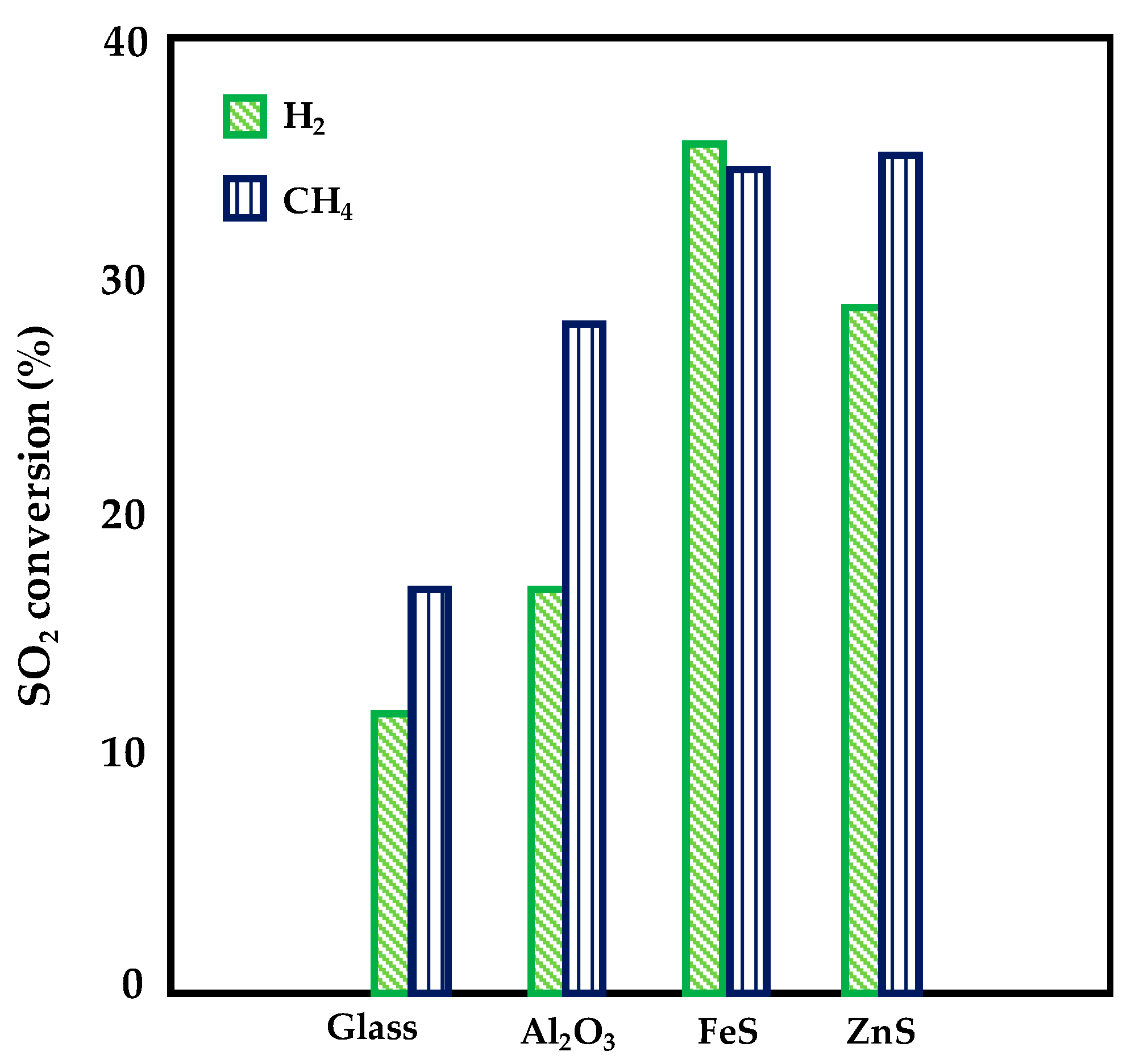
| Al2O3 | DBD | 10 W DBD plasma 1% SO2, 4% H2, N2 balance, flow rate = 100 mL min−1 at 150 °C, 1 atm | 17 | [51] |
| FeS/Al2O3 | DBD | 10 W DBD plasma 1% SO2, 4% H2, N2 balance, flow rate = 100 mL min−1 at 150 °C, 1 atm | 31 | [51] |
| ZnS/ Al2O3 | DBD | 10 W DBD plasma 1% SO2, 4% H2, N2 balance, flow rate = 100 mL min−1 at 150 °C, 1 atm | 28 | [51] |
| Al2O3 | DBD | 10 W DBD plasma 1% SO2, 4% CH4, N2 balance, flow rate = 100 mL min−1 at 150 °C, 1 atm | 27 | [51] |
| FeS/Al2O3 | DBD | 10 W DBD plasma 1% SO2, 4% CH4, N2 balance, flow rate = 100 mL min−1 at 150 °C, 1 atm | 34 | [51] |
| ZnS/Al2O3 | DBD | 10 W DBD plasma 1% SO2, 4% CH4, N2 balance, flow rate = 100 mL min−1 at 150 °C, 1 atm | 35 | [51] |
| TiO2 | DBD | 900 Hz, 7 kV, residence time = 1 s SO2 = 100 ppm, H2O = 4%, SO2/NH3 = 2 21% O2 and N2 balancing 1 atm, 25 °C | 100 | [52] |
| TiO2 | DBD | 900 Hz, 7 kV, residence time = 1 s SO2 = 600 ppm, H2O = 4%, SO2/NH3 = 2 21% O2 and N2 balancing 1 atm, 25 °C | 16 | [52] |
| TiO2 | DBD | 900 Hz, 9 kV, residence time = 1 s SO2 = 400 ppm, H2O = 4%, SO2/NH3 = 2 21% O2 and N2 balancing 1 atm, 25 °C | 77 | [52] |
| TiO2 | DBD | 100 Hz, 9 kV, residence time = 1 s SO2 = 400 ppm, H2O = 4%, SO2/NH3 = 2 21% O2 and N2 balancing 1 atm, 25 °C | 9 | [52] |
| TiO2 | DBD | 900 Hz, 9 kV, residence time = 1 s SO2 = 400 ppm, H2O = 4%, SO2/NH3 = 2 21% O2 and N2 balancing 1 atm, 25 °C | 55 | [52] |
| TiO2 | DBD | 900 Hz, 9 kV, residence time = 0.32 s SO2 = 400 ppm, H2O = 4%, SO2/NH3 = 2 21% O2 and N2 balancing 1 atm, 25 °C | 18 | [52] |
| TiO2 deposited via dip-coating | DBD | 900 Hz, 9 kV, residence time = 1 s SO2 = 420 ppm 21% O2 and N2 balancing 1 atm, 25 °C | 45 | [53] |
| TiO2 deposited via PCVD (layer thickness 150 nm) | DBD | 900 Hz, 9 kV, residence time = 1 s SO2 = 420 ppm 21% O2 and N2 balancing 1 atm, 25 °C | 68 | [53] |
| TiO2 deposited via PCVD (layer thickness 35 nm) | DBD | 900 Hz, 11 kV, residence time = 1 s SO2 = 260 ppm 21% O2 and N2 balancing 1 atm, 25 °C | 15 | [54] |
| TiO2 deposited via PCVD (layer thickness 600 nm) | DBD | 900 Hz, 11 kV, residence time = 1 s SO2 = 260 ppm 21% O2 and N2 balancing 1 atm, 25 °C | 100 | [54] |
| Zeolite without TiO2 coating | DBD | 900 Hz, 12 kV, residence time = 1 s SO2 = 200 ppm 21% O2 and N2 balancing 1, 25 °C | 31 | [55] |
| Zeolite with TiO2 coating | DBD | 900 Hz, 12 kV, residence time = 1 s SO2 = 200 ppm 21% O2 and N2 balancing 1 atm, 25 °C | 58 | [55] |
| γ-Al2O3 | DBD | 7 W DBD Plasma NO = 440 ppm, NO2 = 14 ppm, SO2 = 460 ppm 21% O2 and N2 balancing Reacting flow rate: 600 mL min−1 | 24 | [56] |
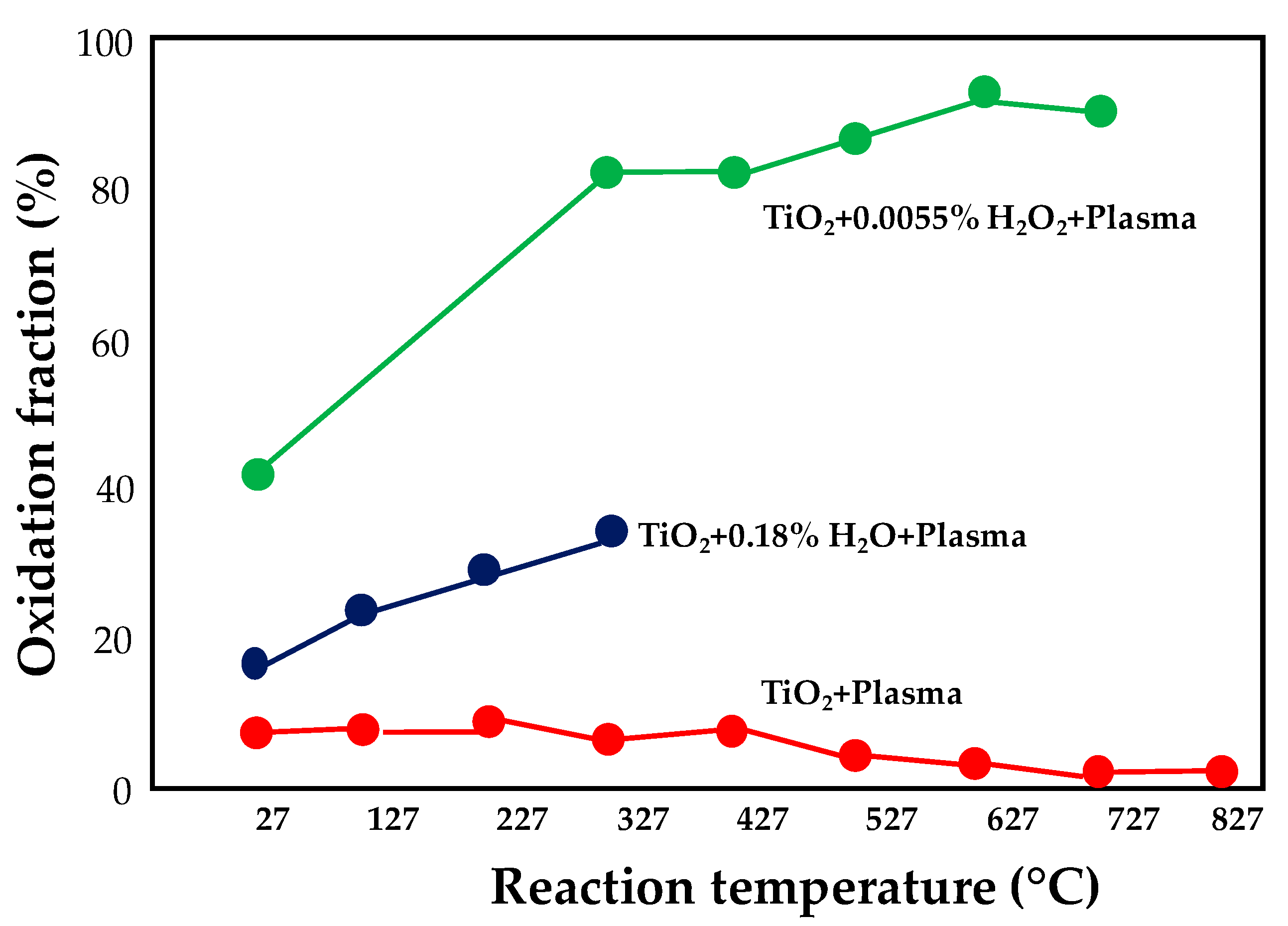
| TiO2 | PCP | 12.5 kV SO2: 906 ppm (N2 basis); O2: 2.1%; H2O: 0.18%; H2O2: 0.055% Reacting flow rate: 1 L min−1 1 atm, 25 °C | 42 | [44] |
| Catalysts | NTP Technology | Operative Conditions | H2S Conversion (%) | Ref. |
|---|---|---|---|---|
| CdS/Al2O3 | DBD | 10 kHz, 6.12 eV/H2 20% O2 in Ar Reacting flow rate: 30 mL min−1 1 atm, 120 °C | 90.9 | [66] |
| ZnS/Al2O3 | DBD | 10 kHz, 6.12 eV/H2 20% O2 in Ar Reacting flow rate: 30 mL min−1 1 atm, 120 °C | 82.9 | [66] |
| Zn0.4Cd0.6S/Al2O3 | DBD | 10 kHz, 6.12 eV/H2 20% O2 in Ar Reacting flow rate: 30 mL min−1 1 atm, 120 °C | 97.9 | [66] |
| Zn0.6Cd0.4S/Al2O3 | DBD | 10 kHz, 6.12 eV/H2 20% O2 in Ar Reacting flow rate: 30 mL min−1 1 atm, 120 °C | 100 | [68] |
| Zn0.2Cd0.8S/Al2O3 | DBD | 10 kHz, 6.12 eV/H2 20% O2 in Ar Reacting flow rate: 30 mL min−1 1 atm, 120 °C | 92.8 | [68] |
| Zn0.8Cd0.2S/Al2O3 | DBD | 10 kHz, 6.12 eV/H2 20% O2 in Ar Reacting flow rate: 30 mL min−1 1 atm, 120 °C | 84.9 | [68] |
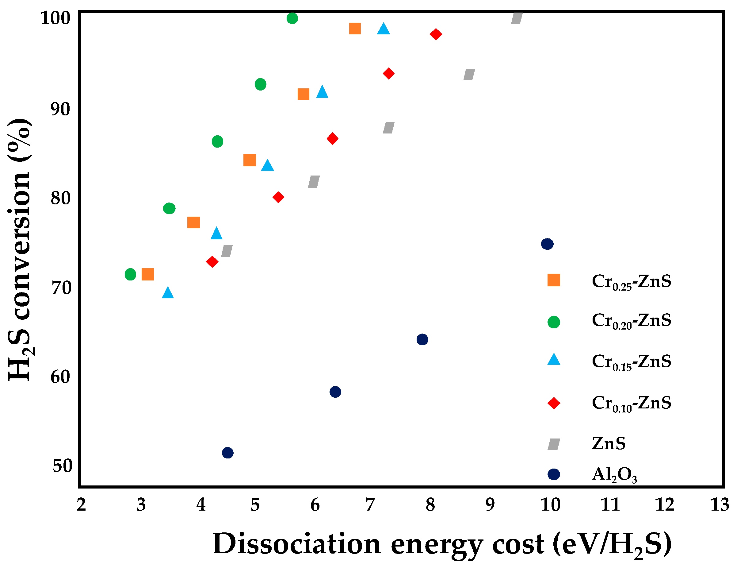
| Cr0.20–ZnS/Al2O3 | DBD | 10 kHz, 5.57 eV/H2 20% O2 in Ar Reacting flow rate: 30 mL min−1 1 atm, 120 °C | 100 | [69] |
| Cr0.25–ZnS/Al2O3 | DBD | 10 kHz, 5.57 eV/H2 20% O2 in Ar Reacting flow rate: 30 mL min−1 1 atm, 120 °C | 89.7 | [69] |
| Cr0.15–ZnS/Al2O3 | DBD | 10 kHz, 5.57 eV/H2 20% O2 in Ar Reacting flow rate: 30 mL min−1 1 atm, 120 °C | 87.4 | [69] |
| Cr0.10–ZnS/Al2O3 | DBD | 10 kHz, 5.57 eV/H2 20% O2 in Ar Reacting flow rate: 30 mL min−1 1 atm, 120 °C | 81.8 | [69] |
| 1-wt% MoS2/Al2O3 | DBD | 10 kHz, 95 kJ·L−1 H2S/CO2 ratio = 20:15 Reacting flow rate: 35 mL min−1 1 atm, 120 °C | 94 | [70] |
| 5-wt% MoS2/Al2O3 | DBD | 10 kHz, 95 kJ·L−1 H2S/CO2 ratio = 20:15 Reacting flow rate: 35 mL min−1 1 atm, 120 °C | 99 | [70] |
| 10-wt% MoS2/Al2O3 | DBD | 10 kHz, 95 kJ·L−1 H2S/CO2 ratio = 20:15 Reacting flow rate: 35 mL min−1 1 atm, 120 °C | 97 | [70] |
| 15-wt% MoS2/Al2O3 | DBD | 10 kHz, 95 kJ·L−1 H2S/CO2 ratio = 20:15 Reacting flow rate: 35 mL·min−1 1 atm, 120 °C | 92 | [70] |
| 3-wt% MoOx/Al2O3 | DBD | 10 kHz, 1 W 5% H2S/Ar Reacting flow rate: 150 mL min−1 1 atm, 160 °C | 48 | [71] |
| 5-wt% MoOx/Al2O3 | DBD | 10 kHz, 1 W 5% H2S/Ar Reacting flow rate: 150 mL min−1 1 atm, 160 °C | 52 | [71] |
| 7-wt% MoOx/Al2O3 | DBD | 10 kHz, 1 W 5% H2S/Ar Reacting flow rate: 150 mL min−1 1 atm, 160 °C | 45 | [71] |
| Fe/WSAC Treated for 10 min at 6.8 kV | DBD | 7.8 kHz, 6.8 kV 500 ppm of H2S in N2 Reacting flow rate: 60 mL min−1 1 atm, 60 °C | 100 for 270 min | [72] |
| Fe/WSAC Treated for 10 min at 6.8 kV with a gas gap of 5.5 mm and a dielectric thickness of 1.5 mm | DBD | 7.8 kHz, 6.8 kV 500 ppm of H2S in N2 Reacting flow rate: 60 mL min−1 1 atm, 60 °C | 100 for 210 min | [73] |
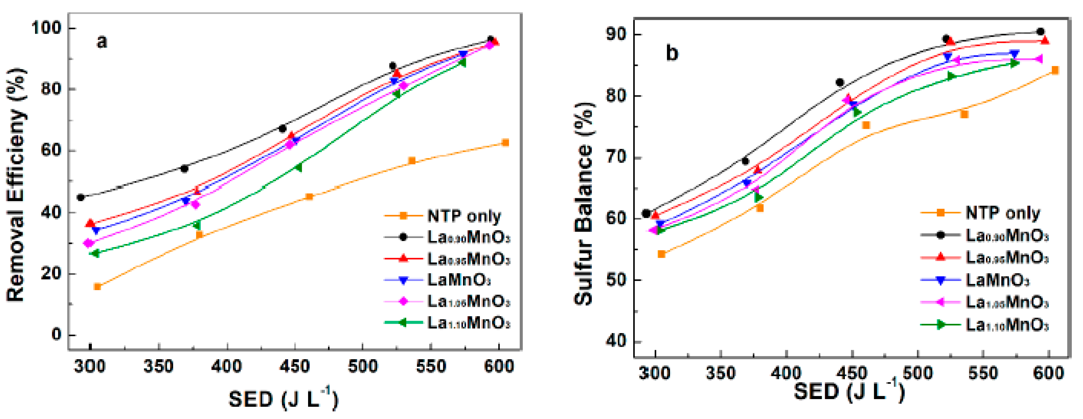
| La0.9MnO3 | DBD | 10 kHz, 593.7 J·L−1 100 ppm of H2S in air Reacting flow rate: 2 L min−1 1 atm, 80 °C | 96.4 | [74] |
| Mn2O3 | DBD | 50 Hz, 22 kV 200 mg m−3 H2S, 1200-mg·m−3 O3 in air Reacting flow rate: 0.2 m3 h−1 | 100 | [75] |
| Ag2O | DBD | 50 Hz, 22 kV 200 mg m−3 H2S, 1200-mg m−3 O3 in air Reacting flow rate: 0.2 m3 h−1 | 98 | [75] |
| CuO | DBD | 50 Hz, 22 kV 200 mg m−3 H2S, 1200-mg·m−3 O3 in air Reacting flow rate: 0.2 m3 h−1 | 82 | [75] |
| Fe2O3 | DBD | 50 Hz, 22 kV 200 mg m−3 H2S, 1200-mg m−3 O3 in air Reacting flow rate: 0.2 m3 h−1 | 75 | [75] |
| Catalytic Removal via NTP Technology | ||||
| Catalyst Formulation | NTP Technology | Operative Conditions | NOx Removal Efficiency % (Maximum Value Reached) | Reference |
| Ag/Al2O3 | DBD | 16–23 kHz, 1–2 W Reacting flow rate: 276 cm3 min−1 NO: 720 ppm Either 540 ppm n-C8H18 or 620 ppm toluene 4.3% O2 7.2% H2O 7.2% CO2 He as carrier gas 1 atm, 25–250 °C | 70 | [80] |
| Ag/α-Al2O3 | DBD | 2 W Reacting flow rate: 2 L min−1 NO: 300 ppm 10% O2 3.2% H2O 265 ppm n-heptane N2 as balance gas | 74 | [81] |
| H–MOR Co–MOR NMOR | DBD | 5 W Reacting flow rate: 60 mL min−1 NO: 2130 ppm 8% O2 He as balance gas T = 35 °C | 99.6 | [82] |
| Co/Ba/Al Pd/Co/Ba/Al Pd particle size = 3.1 nm Pt/Ba/Al Pt particle size = 2.7 nm | DBD | 40 kHz, 20 W (in the rich phase) NO: 500 ppm 8% O2 2% H2O 2% CO2 N2 as balance gas T = 150–350 °C | 90 | [83] |
| M/Ba/Al (M = Mn, Fe, Co, Ni and Cu) | DBD | 0–40 kV, 40 kHz, 1.8 W (in the rich phase) phase) NO: 500 ppm 8% O2 2% H2O Ar as balance gas T = 200–350 °C | 100 | [84] |
| Pt/Ba/Al Pt particle size = 2.7 nm Pd/Co/Ba/Al Pd particle size = 3.1 nm Pd/Ba/Al Pd particle size = 3.5 nm | DBD | 40 kHz, 1.8 W (in the rich phase) NO: 500 ppm 8% O2 2% H2O Ar as balance gas T = 150–350 °C | 99 | [85] |
| Pt/Ba/Al Pt particle size = 2.1 nm Pt/Co/Ba/Al Pt particle size = 1.6 nm Pt/Mn/Ba/Al Pt particle size = 1.8 nm Pt/Cu/Ba/Al Pt particle size = 2.1 nm | DBD | 40 kHz, 1.8 W (in the rich phase) NO: 500 ppm 8% O2 2% H2O Ar as balance gas T = 150–350 °C | 80 | [86] |
| Zeolites (H–ZSM-5) | DBD | 0.03–4 W Reacting flow rate: 66 mL min−1 NO: 1800 ppm 10% O2 He as balance gas 1 atm, 25 °C | 97.8 | [87] |
| Cu-modified CMS | DBD | 7.6 kV, 8.9 kHz, 200 W Reacting flow rate: 300 mL min−1 0.05% NO 3% O2 N2 as balance gas | 96.2 | [88] |
| In/H–BEA zeolite In particle size = 6–10 nm | DBD | 0–1.125 W Reacting flow rate: 500 mL min−1 NO: 440 ppm NO2: 14 ppm CH4: 600 ppm SO2: 0–100 ppm 6% O2 7% H2O Ar as balance gas T = 230–570 °C | 99 | [89] |
| MnCu/TiO2 | DBD–WESP | 8 kHz, 10 kV and 200 W SO2: 0–2000 mg·m−3 NO: 200–400 mg·m−3 10% O2 and N2 balancing Reacting flow rate: 4 L min−1 Cleaning water flow rate: 3.6 L min−1 1 atm, 25 °C | 93.4 | [48] |
| γ-Al2O3 | DBD | 7 W NO: 440 ppm NO2: 14 ppm SO2: 460 ppm 21% O2 N2 balancing Reacting flow rate: 600 mL min−1 1 atm, 25 °C | 45 | [56] |
| Non-Catalytic Removal Via NTP Technology | ||||
| NTP Technology | Operative Conditions | NOx Removal Efficiency % (Maximum Value Reached) | Reference | |
| DBD | 0–7 kV, 1–2000 Hz | – | [90] | |
| Volume barrier discharge (VBD) | 80–500 Hz, 0.56 kW air 30 L min−1 Methane 10 L min−1 | 90 | [91] | |
| DBD | 40 kV, 50 Hz NO: 100 ppm SO2: 300 ppm N2 as balance gas | 80 | [92] | |
| DBD | 16 kHz, 40 kV Reacting flow rate: 1 L min−1 NO: 300 ppm 5% O2 N2 as balance gas | 77 | [93] | |
| DBD | 60 kV, 5–25 kHz Reacting flow rate: 10 L min−1 NO: 500 ppm C2H2: 1000 ppm 6% O2 N2 as balance gas | 40 | [94] | |
| DBD | 0–5 kV, 15 kHz, 45 W Reacting flow rate: 1 L s−1 HC: 10 ppm NOx: 116 ppm 3.32% CO2 0.5% CO 17.03% O2 | 95 | [95] | |
| DBD | 23 kV, 20 kHz, 250 W Reacting flow rate: 150 L min−1 NO: 350 ppmv SO2: 800 ppmv | 88.8 | [96] | |
| DBD | 0–7 kV, 60 Hz NO: 300 ppm SO2: 0–1000 ppm 4.2% O2 N2 as balance gas | 100 | [97] | |
| Catalyst Formulation (Particle Size [nm]) | NTP Technology | Operative Conditions | Soot-Removal Efficiency [g·kWh−1] (Maximum Value Reached) | Reference |
|---|---|---|---|---|
| Fe2O3 (14.6) MnOx (168.1) Co3O4 (53.3) | Corona plasma reactor | 0–20 kV, 4–7.5 W 300 sccm of feed gas containing 10% O2 in N2 Electrode surface coated with 3.5 mg of soot Residence time: 0.94 s 1 atm, 180–350 °C | 7.0 with MnOx | [102] |
| Au, Pt, Pd and Ag (not specified) | DBD | 5–6 kV, 4.5 W Reacting flow rate: 1 L min−1 20% O2 20 mg of PM dispersed in 2 mL of liquid ethanol, uniformly loaded on the alumina plate surface t = 1 h 1 atm, 100–250 °C | 6.1 with Au | [104] |
| AgCe–C (Ag crystallite size < 3 nm, CeO2 crystallite size = 25.1 nm) AgCe–R (Ag crystallite size < 3 nm, CeO2 crystallite size = 14.8 nm) | O3 activation | O3/air flow = 1 L/min O3 concentration of 400 ppm T = 200 °C | Not specified | [105] |
| MgSO4 K2SO4 CaSO4·2H2O (not specified) | DBD | 7.4–8 kV, 4.5 W 800 mL·min−1 of N2 200 mL·min−1 of O2 10 mg of PM dispersed in 1-mL aqueous ethanol, mixed with a 500-μL aqueous solution of metal sulfate T = 100–250 °C | 3.8 with K2SO4 | [106] |
| Ag/α-Al2O3 (not specified) | DBD | Reacting flow rate: 2 L min−1 300 ppm of NO 265 ppm of n-heptane 48 ppm of naphthalene (soot simulant) 10% O2 3.7% H2O N2 as balance gas T = 150–350 °C | Not specified | [107] |
| Catalyst Formulation (Metal Particle Size *) | NTP Technology | Operative Conditions | Ref. |
|---|---|---|---|
| TiO2/g–C3N4 | DBD | 4–12 kHz, 20–60 W Feed flowrate = 50 mL min−1 CO2:CH4 = 6:1 to 1:6 | [115] |
| Ni/γAl2O3–MgO (12 nm) | DBD | 1–30 kV, 7.5 kHz, 100 W Feed flowrate = 20 mL min−1 CH4:CO2 = 1 | [116] |
| Ni/La2O3–MgAl2O4 (10.77 nm) | DBD | 1–30 kV, 7.5 kHz, 100 W Feed flowrate = 20 mL min−1 CH4:CO2 = 1 T = 350 °C | [117] |
| Ni/La2O3–MgAl2O4 | DBD | 1–30 kV, 7.5 kHz, 33–116 W Feed flowrate = 20 mL min−1 CH4:CO2 = 1 | [118] |
| Ni/Al2O3 (<6 nm) | DBD | 12–26 kV, 50 Hz, 1.4–4.8 W CH4: 10% vol in Ar balance CO2: 5% vol in Ar balance Feed flowrate = 40 mL min−1 CH4:CO2 = 1: 2, 1:1, 2:1 | [119] |
| BZT; BFN; glass beads | DBD | 12.1–13.6 kV, 20 kHz Feed flowrate = 40 mL min−1 CH4:CO2 = 1 | [120] |
| Ni/γ-Al2O3 | DBD | 30 kV, 10 kHz, 20–60 W Feed flowrate = 25–125 mL min−1 CH4:CO2 = 1 | [121] |
| La2O3/alumina balls | DBD | 24 kV, 800 Hz, 8 W Feed flowrate = 40 mL min−1 CO2:CH4 = 0.4, 1, 2.3 He dilution: 33.3%, 50%, 75% | [122] |
| Ni/AC | DBD | 30 kV, 5–12 kHz, 45 W Feed flowrate = 50 mL min−1 CH4:CO2 = 1 T = 270 °C | [123] |
| Ni/α-Al2O3 | DBD | 15 kV, 5–30 kHz Feed flowrate = 100 mL min−1 CH4:CO2 = 1 | [124] |
| NiCexC (23.7–31.1 nm) | DBD | 8.5 kHz, 40 W CH4:CO2 = 3:1 to 1:3 Feed flowrate = 50 mL min−1 CH4:CO2 = 1 T = 260 °C | [125] |
| ZrO2; UiO-67; 2% PtNP@UiO-67 (1–4 nm) | DBD | 6–10 kV, 30 kHz, 11 W CH4 up to 5000 ppm in Ar balance CO2 up to 5000 ppm in Ar balance Feed flowrate = 100 mL min−1 CH4:CO2 = 0.5–1.5 | [126] |
| LaNiO3@SiO2 NP (40 nm) | DBD | 30 kV, 5–100 kHz, 50–200 W Feed flowrate = 50 mL min−1 CH4:CO2 = 1 | [128] |
| CaO; CaCO3; Ca(OH)2 | DBD | 13.5 kV, 800 Hz, 8 W Feed flowrate = 40 mL min−1 CH4:CO2 = 2 T = room T; 100 °C | [130] |
| Pt–Sn/Al2O3; BaTiO3; HZSM-5 | DDBD | Generator: CTP-2000 K (9 kHz) Power: 8.1–65.8 W | [131] |
| – | Gliding arc discharge | Frequency: 50 Hz | [132] |
| – | RGA | 0.74–1.50 A Feed flowrate = 3.7; 4.7; 6.7 SLPM CO2:CH4 = 1; 1.5; 2 Tpre-heating = room T; 200 °C | [133] |
| Catalyst Formulation (Metal Particle Size [nm]) | NTP Technology | Operative Conditions | Ref. |
|---|---|---|---|
| Ni/γ-Al2O3 (14 nm) | DBD | 12–29 kV, 100 Hz, 3.6 W Feed flowrate = 640 mL min−1 CO2:H2 = 1:4 T range = 100–400 °C | [137] |
| Ni/γ-Al2O3 (<4.3 nm) | DBD | 10 kV, 52–55 kHz, 15–18 W Feed flowrate = 50 mL min−1 CO2:H2 = 1:4 T range = 150–400 °C | [138] |
| Ni/Ce0.58Zr0.42O2 | DBD | 15–19 kV, 41 kHz, 4–16 W Feed flowrate = 20–350 mL min−1 CO2:H2 = 1:4 T range = 130–255 °C | [139] |
| Ni/MOFs | DBD | 6.0–7.5 kV, 20.3 kHz CO2:H2 = 1:4 | [140] |
| Ni–CeO2/Al2O3 | DBD | 4–9 kV, 52 kHz, 5–25 W Feed flowrate = 200–1000 mL min−1 CO2:H2 = 1:4 | [141] |
© 2020 by the authors. Licensee MDPI, Basel, Switzerland. This article is an open access article distributed under the terms and conditions of the Creative Commons Attribution (CC BY) license (http://creativecommons.org/licenses/by/4.0/).
Share and Cite
Palma, V.; Cortese, M.; Renda, S.; Ruocco, C.; Martino, M.; Meloni, E. A Review about the Recent Advances in Selected NonThermal Plasma Assisted Solid–Gas Phase Chemical Processes. Nanomaterials 2020, 10, 1596. https://doi.org/10.3390/nano10081596
Palma V, Cortese M, Renda S, Ruocco C, Martino M, Meloni E. A Review about the Recent Advances in Selected NonThermal Plasma Assisted Solid–Gas Phase Chemical Processes. Nanomaterials. 2020; 10(8):1596. https://doi.org/10.3390/nano10081596
Chicago/Turabian StylePalma, Vincenzo, Marta Cortese, Simona Renda, Concetta Ruocco, Marco Martino, and Eugenio Meloni. 2020. "A Review about the Recent Advances in Selected NonThermal Plasma Assisted Solid–Gas Phase Chemical Processes" Nanomaterials 10, no. 8: 1596. https://doi.org/10.3390/nano10081596