Review

Sulfide and Oxide Inorganic Solid Electrolytes for All-Solid-State Li Batteries: A Review

1
Centre of Excellence in Transportation Electrification and Energy Storage (CETEES), Institute of Research Hydro-Québec, 1806, Lionel-Boulet Blvd., Varennes, QC J3X 1S1, Canada
2
Institut de Minéralogie, de Physique des Matériaux et de Cosmochimie (IMPMC), Sorbonne Université, UMR-CNRS 7590, 4 place Jussieu, 75252 Paris, France
3
Department of Mining and Materials Engineering, McGill University, Wong Building, 3610 University Street, Montreal, QC H3A OC5, Canada
*
Authors to whom correspondence should be addressed.
Nanomaterials 2020, 10(8), 1606; https://doi.org/10.3390/nano10081606
Submission received: 17 July 2020 / Revised: 8 August 2020 / Accepted: 11 August 2020 / Published: 15 August 2020

Abstract

:
Energy storage materials are finding increasing applications in our daily lives, for devices such as mobile phones and electric vehicles. Current commercial batteries use flammable liquid electrolytes, which are unsafe, toxic, and environmentally unfriendly with low chemical stability. Recently, solid electrolytes have been extensively studied as alternative electrolytes to address these shortcomings. Herein, we report the early history, synthesis and characterization, mechanical properties, and Li+ ion transport mechanisms of inorganic sulfide and oxide electrolytes. Furthermore, we highlight the importance of the fabrication technology and experimental conditions, such as the effects of pressure and operating parameters, on the electrochemical performance of all-solid-state Li batteries. In particular, we emphasize promising electrolyte systems based on sulfides and argyrodites, such as LiPS5Cl and β-Li3PS4, oxide electrolytes, bare and doped Li7La3Zr2O12 garnet, NASICON-type structures, and perovskite electrolyte materials. Moreover, we discuss the present and future challenges that all-solid-state batteries face for large-scale industrial applications.

1. Introduction

Inorganic oxide and sulfide materials have recently been studied as solid electrolytes for all-solid-state batteries (ASSBs) owing to their high safety profile, wide temperature window, and better mechanical properties than those of liquid electrolytes. Solid-state electrolytes (SSEs) can be widely used for solid-state Li batteries [1,2], sensors [3,4], fuel cells [1], Li-air [1,5,6], and Li-S [7] batteries. Although solid-state electrolytes can be used for all these different applications, we focused mainly on electrolytes for all-solid-state Li batteries. Recently, Reddy et al. [8] summarized the early history of Li batteries. In brief, a Li battery consists of a cathode (positive electrode), an electrolyte (Li ionic conductor), a separator, and an anode (negative electrode). The cathode material consists of either LiCoO2 (LCO), Li(NixMnyCoz)O2 (NMC), LiFePO4 (LFP), or LiMn2O4 (LMO), and in some cases intercalated binary oxides, whereas Li metal, Li-In alloys, graphite, Li4Ti5O12 (LTO), or Si, Sn-Co-C mixed composites are used as anode materials [2]. In addition, Li batteries use liquid [9], gel polymer [10,11,12], or combinations of polymer and solid electrolytes. The electrode preparation techniques for all-solid-state lithium batteries (ASSLBs) differ from those of commercial Li batteries. Furthermore, the fabrication technologies of oxide and sulfide electrolyte-based ASSBs are different. For example, carbon is used as a conductive additive during the fabrication of sulfide electrolytes but not for the fabrication of oxide electrolytes. Moreover, depending on the mechanical properties of sulfide electrolytes, a suitable stack pressure is required for the assembly of ASSBs. Oxide solid electrolytes require high-temperature (>700 °C) sintering to improve the particle-particle contact between electrode and electrolyte. The general schematic diagram of ASSBs is presented in Figure 1. The ideal electrolyte materials for ASSBs should feature the following important properties: (i) High ionic conductivity of 10−3 S cm−1 at room temperature, (ii) low electronic conductivity of <10−8 S cm−1, which prevents their self-discharge, (iii) wide electrochemical potential window, (iv) good chemical stability over the operating temperature range and toward the electrodes, (v) transference number of approximately 1, (vi) matching thermal expansion coefficients with the cathode materials, (vii) good chemical stability; no crystal structure phase transformation should occur for the electrode active materials up to/near their sintering temperatures, (viii) their sintering temperature should match that of the electrode active materials, and (xv) low toxicity and cost effective [13].
Many researchers have investigated new solid electrolytes to replace flammable liquid electrolytes or improve the performance of existing solid electrolytes and elucidate their fundamental properties and technological developments. Huggins (1977) [14], Weppner (1981) [15], Kulkarni et al. (1984) [16], Minami (1985) [17], Pardel and Ribes (1989) [18], Adachi et al. (1996) [19], Owens (2000) [20], Thangadurai and Weppner (2002) [21], Knauth (2009) [22], and Fergus (2010) [23] published reviews on solid electrolytes. The journal Solid State Ionics devoted to these materials was created in 1980. This has been considered a hot research topic worldwide and has generated many publications. To highlight the advances on solid electrolyte fundamentals and electrode/electrolyte interface, analysis and its applications have been reviewed by many workers. We highlight a few important reviews in the following section.
The large number of reviews on solid electrolytes published during the last five years was attributed to the increasing interest in the use of solid electrolytes for electric vehicles (EVs) applications owing to their safety. Tatsumisago et al. [24] and Sakuda et al. [25] published important reviews on sulfide electrolytes, while Thangadurai et al. [26,27] reviewed garnet electrolytes. Furthermore, the fundamentals of ASSBs were reviewed by several authors [28,29,30,31,32,33,34,35]. The number of reviews on various aspects of electrolytes, cathodes, mechanical properties, and interface engineering has grown exponentially since 2018 [36,37,38,39,40,41,42,43,44,45,46,47,48,49,50,51,52,53,54,55,56,57,58,59,60,61,62,63,64,65,66,67,68,69,70,71,72,73,74,75,76,77,78,79,80,81,82,83,84,85,86,87,88,89,90,91,92,93,94,95,96,97,98,99,100,101,102,103,104,105,106,107,108,109,110,111,112,113,114,115]. For example, Famprikis et al. [51] and Zhang et al. [116] reported on the fundamentals of electrolytes and Oudenhoven et al. [117], Julien and Mauger [60], and Rambabu et al. [118] reviewed the technology of solid-state microbatteries. Moreover, in situ and ex situ techniques were explored for elucidating the solid electrode/electrolyte interfaces [40,67,80,98,119,120,121,122,123] and computational methods were reviewed by Xiao et al. [94] for understanding the conduction mechanisms in both oxide and sulfide electrolytes.
Herein, we report the brief history of each electrolyte system, summarize the recent advances in solid electrolytes (oxides vs. sulfides) for ASSB applications, highlight the importance of the cell fabrication technology and process parameters on the electrochemical storage performance, mechanical properties, and interfacial mechanisms of the cells, and examine the challenges of the large-scale fabrication of ASSBs. Furthermore, we summarize the important recent reports on electrolyte materials. Owing to the vast literature on this topic, we were unable to include and highlight all the pertinent publications in this review; however, some of the older publications are referenced in the most recent reviews.

2. Ionic Conduction in the Solid State

2.1. Ionic Conduction

In an idealized crystalline structure, there is little space for an ion to diffuse. The available space is only limited for vibration around its equilibrium position. In real systems, the degree of disorder that generates point defects (Schottky or Frenkel defects) results in vacant sites in the crystal and any ion in the immediate vicinity can jump from lattice site to lattice site. Ionic conduction is provoked by the motion of some positively (or negatively) charged ions, which “hop” under the influence of an electric field F. This ionic conductivity σi is expressed by:
σi = ni e µi,
where ni is the number of ions per unit volume, µi the mobility of ions and e their charge. To move through the crystalline network, ions must have sufficient energy to pass an energy barrier Ea. Thus, ni in Equation (1) depends on the defect concentration in the crystal. So, in ionic frameworks, the movement of ions is in fact the movement of vacancies. Regarding the defect concentration, a useful classification of solid-state ionic conductors was proposed by Rice and Roth [124] as follows:
  • Type I: Ionic solids with low concentration of defects ~1018 cm−3 at room temperature. They include compounds with poor ionic conduction (NaCl, LiCl, etc.).
  • Type II: Ionic solids with high concentration of defects ~1020 cm−3 at room temperature. They are good ionic conductors (“fast-ionic conductors”, FICs), which belong to the class of materials of “vacancy migration”.
  • Type III: Best FICs, which have a “molten” sub-lattice or “liquid like” structure of the mobile ions whose concentration is typically 1022 cm−3. The conduction mechanism in such FICs is mostly “interstitial”.
In practice, for a useful solid electrolyte, the electronic conductivity σe is undesirable and the transference number ti is defined as the ratio of the ionic conductivity to the total conductivity
ti = σi /(σe + σi) ≈ 1.
In the one-dimensional (1D) model, the probability per unit time (P) for a vacancy to move to the next position in the absence of electric field is given by:
P = ν 0 exp ( E a k B T ) ,
where ν0 is the attempt frequency, T is the absolute temperature, kB is the Boltzmann constant, and Ea is the potential barrier height or activation energy. Under an electric field, the barrier height is changed by the quantity eFa (see Figure 2a), where a is the lattice constant. The probabilities for the vacancy to move in the direction of the field (P′) and in the opposite direction to the field (P″) can be written as:
P = ν 0 exp ( E a + 1 2 e F a k B T ) ,
P = ν 0 exp ( E a 1 2 e F a k B T ) .
The velocity of the vacancy in the lattice is expressed by:
ν i = a ( P P ) = a ν 0 exp ( E a k B T ) × 2 sinh ( e F a 2 k B T ) .
For low electric field, eFa << kBT, taking the Taylor series expansion of sinh(x) ≈ x, the last term equals to eFa/2kBT and Equation (6) is simplified to:
ν i = a 2 e F ν 0 k B T exp ( E a k B T ) .
Hence, the mobility of vacancies is expressed as:
μ i = a 2 e ν 0 k B T exp ( E a k B T ) .
Combining Equations (1) and (8), the ionic conductivity can be expressed as:
σ i = n i a 2 e ν 0 k B T exp ( E a k B T ) ,
which can be simplified (Arrhenius equation), in which the first term σ0 = nia2e2ν0/kBT is the conductivity pre-factor:
σ i = σ 0 exp ( E a k B T ) .
Note that, in polycrystalline materials, Ea appears to be dependent on the crystallite size. The Nernst–Einstein relation relates the ionic conductivity to the diffusion coefficient of ions as:
σ i = n i e 2 D i k B T .
The typical Arrhenius plot for an idealized ionic conductor shown in Figure 2b presents two regions. At low temperature, the conductivity (activation energy Em) is dominated by the mobility of extrinsic defects. The carrier (ion) concentration is fixed by doping. For example, an improved conductivity of 0.5 mS cm−1 at room temperature was obtained for Li6PS5Cl doped with few mol% of LiCl. At high temperature, the conductivity is due to thermally formed intrinsic defects. The carrier concentration varies with temperature and the slope reflects the activation energy Ea, required for the creation of vacancies. Ea is obtained from the slope of the semi-logarithmic Arrhenius plot (Equation 10):
ln σ i = ln σ 0 E a k B T ,
E a = Δ ln σ i Δ ( 1 T ) × k B ,
with kB = 1.38 × 10⁻²³ J K−1, Ea is expressed in Joule or in eV (using the conversion 1 eV = 1.6 × 10⁻¹⁹ J).
In many substances, not only in solid polymer electrolytes (SPEs) and ionic conducting glasses (ICGs) but also in Li0.5La0.5TiO3 perovskite-type FICs [125], for example, the ionic conductivity does not follow the Arrhenius law due to strong ion–ion interactions. The temperature dependence of the dc conductivity can be fitted to an empirical Vogel–Fulcher–Tamman (VFT) function of the form:
σ i = A T exp ( B k B ( T T 0 ) ) ,
where A is the pre-exponential factor, B is the activation energy, and T0 is the temperature at which the free volume to transfer Li+ ions is zero. Usually, T0 is the same as the glass transition temperature (Tg) in SPEs or glassy electrolytes. The ‘‘nonexponentiality’’ observed in electrical conductivity relaxation has been examined using several models, such as the coupling model [126], diffusion-controlled model, [127] or the jump relaxation model [128].

2.2. Ionic Transport Models

Several classes of transport models for the high ionic conduction in FICs have been developed (for a summary, see [129]). Thus, theories, i.e., discrete and continuous models of conduction, have played a central role in the field of FICs for optimization of materials. The reader can find a detailed description in review articles by Mahan [130], Boyce and Huberman [131], Dieterich et al. [132], and Geisel [133]. Specific and indirect assumptions are involved in most of the models such as microstructure, distribution, and local environment of ions.
  • Continuous models are concerned with the motion of ions as Brownian particles in periodic potential. This approach allows the complete description of the dynamics of superionic conductors and explains the local motion in vacant sites of the host lattice (i.e., the local motion includes relaxation and oscillating processes).
  • Discrete models are hopping or random-walk models, which have long been used to study diffusion processes. There are rather simple, and a complete discussion of their dynamical properties is possible. The situation is the following: The lattice defines a periodic array of sites where the mobile ions can sit. An ion placed at one site is licked out of it after a certain time and hops away. Discrete models are applied to ionic conductors where the diffusing ions are well localized about given lattice sites over most of the time.
A common feature of these models is the fact that only the sub-system of diffusing ions is treated explicitly. This simplification can be justified by the fact that usually the characteristic rate τ−1 for particle jump is much smaller than a typical lattice vibrational frequency ωD with ωD τ >>1 [132].
Transport models proposed to explain the high ionic conductivity include the weak electrolyte model [134], the random site model [135], the dynamic structure model [136], the diffusion pathway model [137], the modified random network (MRN) model [138], the dynamic cluster model [139], the cluster-bypass model [140], jump relaxation model [141], lattice-gas model [132], and liquid-like model [132]. These models are briefly presented as follows.
The weak electrolyte model proposed by Ravaine [134] is applied for the ionic transport in materials with lack of long-range order (glasses). Conversely, µi is assumed to be independent of ion concentration, and only weakly temperature dependent, whereas ni depends strongly on both concentration and temperature.
The random site model considers the existence of a wide continuous distribution of alkali ion sites of differing free energies. A clear distribution between mobile and immobile species cannot be made; thus, in this case, the summation of conductivities (Equation (1)) must be performed over the entire distribution of ions [135].
In the dynamic structure model reported by Maas et al. [136], the ion transport in glass is presented by postulating the existence of a site memory effect to visualize the formation of conducting pathways. This quantitative theory explains the general occurrence of the mixed cation (alkali) effect in glassy material and, in addition, shows that the anomalous dependence of conductivity on the modifier content in single alkali glasses follows a simple power-law relation.
In the diffusion pathway model, the spatial dependence of the conductivity is understood by the possible ion transport in the grains and at the grain boundaries, including intergranular pathways within and between grains. Polycrystalline model can quantify the impact of grain boundaries on conductivity as a function of grain size. Such insights provide valuable fundamental understanding of the role of grain boundaries. The lowest energy of grain boundaries the higher electrochemical performance.
The modified random network (MRN) model is appropriate to describe the ionic transport in glasses [138], which comprise two interlacing sublattices: Domains constructed from network former and inter-network regions made up of modifier. For example, in oxide glasses, the strong correlations associated with the network forming units masked the weak correlations between modifying cations and the oxygen sublattice.
The dynamic cluster model [139] is based on the idea that ion-hopping processes are directly coupled to localized structural relaxations occurring in glass even below Tg, while the cluster-bypass model [140] states that ion diffusion occurs within microregions or clusters of material resembling to crystal. In the jump relaxation model described by Funke [141], two competing relaxation processes are considered after each initial forward hop of a charged defect: The backward hop of the defect and the forward motion of the surrounding “defect cloud”. The model yields the power-law of the frequency dependent conductivity.
In the lattice gas model, the role of ion interactions with respect to static properties is most easily investigated by considering the system of conducting ions as a lattice gas. Such a model is characterized by a Hamiltonian, which gives the energy of the various possible configurations. Each configuration is specified by a set of occupation numbers referring to the different lattice sites [132].
The liquid-like model is applicable to the best ionic conductors characterized by very low potential barriers WBkBT, where T ≈ 103 K [132]. Therefore, the probability of finding an ion between preferred lattice sites becomes non-negligible and a discrete lattice gas model is no longer adequate. The mutual repulsion of ions leads to an effective single particle barrier, which differs from the bare potential WB. Such effect is important with respect to transport properties and its discussion requires a continuous many-particle model. The statics of continuous systems to be described is that of a liquid embedded in a periodic medium, for which the total energy is the sum of the periodic single particle potential determined by the forces acting between mobile ions and the cage ions and the pair potential, wich consists of a short-range repulsive part, the Coulomb part, and a phonon mediated part.
The bond-valence method has been used to model both absolute ionic conductivity and activation energy from the “pathway volume” approach. This pathway volume–conductivity relation was found to hold for glassy and crystalline FICs with silver ion conductivities [142] and La2/3−xLi3xTiO3 [143]. Due to the disordered Li sublattice, the Li+ ionic conduction in garnet-type electrolytes is facilitated by a cooperative-type migration instead of a single hopping process with a very small time-scale for fluctuations at intermediate positions [144]. This mechanism was investigated by ab-initio and classical molecular dynamics (MD) studies [145,146]. In the jump diffusion model, the dynamics of the hopping motion of the mobile ions was investigated by Bruesch et al. [147] considering the Brownian motion in a periodic lattice that included the effect of polarizability of the lattice and correlated jumps of ions relevant to superionic conductors. In a modified model, Funke [148] has taken into account the repulsive interaction between mobile ions resulting in a “cage effect”. Because of the cage effect, the ions tend to stay at some distance from each other.

2.3. Impedance Spectroscopy

Ionic conductivity of the solid-state electrolytes is generally measured by the ac complex impedance method (i.e., electrochemical impedance spectroscopy (EIS)). All samples are analyzed within wide range of temperature with a small bias amplitude of 5–10 mV in the frequency range of 106 Hz ~10−2 Hz (pulsation ω). Data are analyzed from the Nyquist plot (−Z″ vs. Z′), the imaginary part −Z″(ω) (capacitive) of the impedance against the real part Z′(ω) (resistive) [149,150]. The conductivity σi (in Scm−1) is calculated using the equation:
σ i = 1 R b d S ,
where d denotes the electrolyte thickness (in cm), S is the cross-sectional area of the electrode (in cm2), and Rb is the bulk electrolyte resistance (in Ω).
For an idealized FIC, the bulk resistance is the quantity obtained from the diameter of the semicircle in the Nyquist plot as shown in Figure 3a. The vertical line in the low-frequency region reflects the capacity formed by the dielectric FIC sandwiched between two metallic electrodes. The equivalent circuit model (inset) consists of the parallel combination of the bulk resistance Rb and the geometry capacity Cb of the FIC (parallel plate capacitor) expressed by:
C b = ε ε 0 S d ,
where ε′ is the permittivity of the material and ε0 is the free-space permittivity (8.854 × 10⁻¹⁴ F cm−1). This Rb,Cb element is in series with a capacity of impedance 1/jωCe (j = √−1), which represents the electrolyte/electrode interface). The ideal impedance of the bulk Zb is given by the expression:
Z b = R b 1 + j ω R b C b =   Z b   +   j Z b ,
where Zb and Zb are the real and imaginary part of the bulk impedance. The −Im(Zb) vs. Re(Zb) plot exhibits a standard semicircle centered at Rb/2. The real and imaginary parts of the impedance are given by Equations (18) and (19):
Z b = R b 1 + ω 2 R b 2 C b 2 ,
Z b = ω R b 2 C b 1 + ω 2 R b 2 C b 2 .
The experimental Nyquist plot of a FIC sample placed between two stainless-steel electrodes is shown in Figure 3b. This diagram deviates from the ideal impedance spectrum as the capacitor in EIS experiments often does not behave ideally. The impedance spectrum consists of a depressed semicircle, which can be visualized by the equivalent circuit including the parallel association of the bulk resistance Rb with the capacitance Cb and a constant phase elements (CPE1), which represents the geometry capacity and the effects of dipolar relaxation (i.e., system with a distribution of time constants), respectively. Similarly, CPE2 replaces the pure Ce capacitance due to surface roughness of the electrode/FIC interfaces. The impedance of a CPE is expressed as:
Z C P E = T ( j ω ) p = T ω p [ cos ( p π 2 ) j sin ( p π 2 ) ] ,
where p is the exponent of CPE (0 < p ≤ 1) and T is the CPE constant (10−3 < T < 10−6). The constant phase is ϕ = − pπ/2.
Figure 4a,b show the frequency dependence of the real Z′(ω) and imaginary −Z”(ω) part of the impedance, respectively, of a FIC sample measured at three temperatures. At ω > 103 Hz, the plots of Figure 4a show a decrease of Z′ vs. frequency, so that σ(ω) increases with frequency (see Figure 4c). At low frequency (f ≈ 1 kHz), σ(ω) increases importantly with temperature. At high frequencies, however, Z′(ω) becomes almost temperature independent so that the Z′(ω) curves at different temperatures merge approximately in a single curve. This is due to the release of space charges caused by reduction in barrier properties of the material [151,152]. This unique curve at high frequency shows a dip, which is associated with charge carrier hopping in the material. On the other hand, Z″ = −Im(Z(ω)) reaches a maximum, which shifts towards higher frequency with temperature. This is attributed to the active conduction through the grain boundaries of the sample. The peak broadening observed with increasing temperature is attributed to a temperature-dependent relaxation process in the material. The asymmetric broadening of the peaks indicates the spread of relaxation time in the sample.
The frequency fm, at which −Im(Z(ω)) goes through a maximum, corresponds to the single relaxation time, which fulfills the relation 2πfmτm = 1. For a thermally activated relaxation process, the variation of τ with T obeys an Arrhenius law given by [153,154]:
τ = τ 0 exp ( E τ k B T ) ,
where τ0 is the pre-exponential factor and Eτ is the activation energy. The inset in Figure 4b shows the temperature dependence of the relaxation time of FIC sample. When the mean relaxation time of the process is measured in fraction of milliseconds, it implies slow relaxation, which can be imposed by permanent molecular dipoles, ion defects of a dipolar type, or mobile hopping charge carriers [31].
The ac conductivity σac (Figure 4c) obeys the power law [153]:
σ(ω) = σac = σ0 + A ωn,
where σ0 is the dc conductivity (at ω ≈ 0), A is a thermally activated quantity, and n is the fractional constant, which is 0.5 < n < 0.8 for an ionic conductor [155]. The frequency exponent n (Equation (4)) can be analyzed by a mechanism based on charge carrier hopping between defect sites proposed by Elliott [156]:
n = ( ln σ a c ) ( ln ω ) = 1 6 k B T E m ,  
where Em is the maximum barrier height (energy of the transport charge). Using Equation (22), from the slope of curves in Figure 4c, one can derive at the highest frequency with n and the value of Em at room temperature.
In practice, solid electrolytes are mainly polycrystalline ceramics with a microstructure composed of intragrains (bulk) of dimension Lb separated from each other by a boundary (intergrain) of thickness Lgb [102,157]. The typical impedance spectrum of polycrystalline FIC (Figure 5a) displays two distinct depressed semi-circles: In the high-frequency range attributable to bulk (intragrain) and in medium-frequency region assignable to grain boundary (intergrain) domains [157]. Thus, the Nyquist plot can be visualized by the equivalent circuit (inset in Figure 5a) including the additional parallel association of the intergrain resistance Rgb with the capacitance Cgb and a constant phase elements (CPEgb). The value of Rgb is obtained from the difference of the intercepts on the Z′ axis:
Rgb = RtRb,
where Rt is the total resistance and Cgb is calculated by applying the equation of the frequency at the semi-circle maximum (ωRgbCgb = 1). Irvine et al. [158] considered the factors controlling the magnitude of the grain boundary impedance using a “brickwork model” (Figure 5b) for an idealized ceramic with cube-shaped grains separated by intergrains of impedance Zgb. From the inverse relation between dielectric thickness and capacitance (Equation 16), for this idealized case, Equation (25) indicates the quality of the sintering and the nature of the narrow intergranular regions:
C b C g b = L g b L b .
For well-sintered samples, generally, the overall impedance of intergrains is 2–3 times greater than the impedance of grains. Typical Arrhenius plot of the conductivities of bulk and grain boundaries is shown in Figure 5c, which display different conduction mechanisms with increase of the intergrain activation energy (Egb > Ea).

3. Sulfide Solid Electrolytes

Owing to their high Li+ ion conductivity at room temperature, sulfide-based materials are more promising electrolytes than oxide-based ones [159,160,161,162,163,164,165,166,167,168,169,170,171,172,173,174,175,176,177,178,179,180,181,182,183,184,185,186,187,188,189,190,191,192,193,194,195,196,197,198,199,200,201,202,203,204,205,206,207,208,209,210,211,212,213,214,215,216,217,218,219,220,221,222,223,224,225,226,227,228,229,230,231,232,233,234,235,236,237,238,239,240,241,242,243,244,245,246,247,248,249,250,251,252,253,254,255,256,257,258,259,260,261,262,263,264,265,266,267,268,269,270,271,272,273,274,275,276,277,278,279,280,281,282,283,284,285,286,287,288,289,290,291,292,293,294,295,296,297,298,299,300,301,302,303,304]. In addition, sulfide-based electrolytes are relatively soft and deformable. Furthermore, the polarizability of sulfide-based electrolytes is higher than that of oxide-based electrolytes, which leads to the attraction between the Li+ ions and sulfide framework being weaker than that between the Li+ ions and oxide framework and the mobility of sulfide-based electrolytes being higher than that of the oxide-based ones. In 1996, Otto [159] reported that the conductivity of the Li2O–Li2Cl2–Li2SO4–SiO2–B2O3 (35:10:30:12.5:12.5) glass system was 3.3 × 10⁻⁶ and 9.7 × 10⁻² S cm−1 at 25 and 350 °C, respectively. In 1997, Calès et al. [160] reported ionic conductivities of 1.0 × 10⁻³ S cm−1 at 300 °C for the B2O3–Li2O–LiX (X = F, Cl, Br, I) and B2O3–Li2O–Li2SO4 borate-based glassy electrolytes; their publication led the search for new sulfide-based electrolyte systems. In 1981, Mercier et al. [161] reported that the room-temperature conductivity of Li2S–P2S5–LiI (Li4P2S7∙LiI) was 10−3 S cm−1. In 1986, Pradel and Ribes [162,163] studied xLi2S(1−x)SiS2 (x ≤ 0.6) and Li2S–M (M = SiS2, GeS2, P2S5, B2S3, As2S3) glasses. Furthermore, in 1986 and 1987, Kennedy [164,165] reported the melt quenching synthesis method and performed conductivity studies on Li2S–SiS2 LiX (X = Br, I); in addition, in 1988 and 1989, Kennedy and Zhang [166,167] investigated the SiS2–P2S5–Li2S–Li2S–LiI system, where LiX acted as an interstitial dopant to improve the ionic conductivity. Rao and Seshasayee [168] conducted molecular dynamics (MD) simulation studies of the x(0.4Li2S–0.6P2S5)–(1 − x)LiI and x(0.5Li2S–0.5P2S5)–(1 − x)LiI (x = 0.9, 0.75) superionic sulfide glasses ternary systems and attributed their high room-temperature ionic conductivity to the presence of non-bridging S atoms around the diffusing Li atoms. Moreover, the decrease in the glass transition temperature (Tg) of these systems was ascribed to the presence of iodine atoms, which led to the plasticization of the structure, rendering it less rigid and decrease in P–P bonds caused by the modifying action of the Li atoms, which also weakened the glass matrix and contributed to the decrease in Tg.
From 1986 to 1989, Akridge and Vourlis [169], Balkanski et al. [170], Meunier et al. [171], Creus et al. [172] and Jones and Akridge [173,174] introduced and developed the thin-film electrolyte concept. In 1995, Takada et al. [175] reported that when ASSBs featuring thin-film cells with the LiMO2 (M = Co, Ni)/Li3PO4 (LPO)–Li2S–SiS2/Li metal electrochemical chain, were cycled at a current rate of 64 µA cm−2 in the voltage range of 2.0–3.8 V, their capacity ranged from 80–90 mAh g−1. Subsequently, different glassy and nanocrystalline sulfide-based electrolytes have been explored by researchers worldwide.
Many research groups studied Li–P–S-based glasses, glass-ceramics, argyrodites, Li6PS5X (X = Cl, Br, I), thio-LISICONs, and Li11−xM2−xP1+xS12 (M = Ge, Sn, and Si) as electrolytes [176,177]. Among all reported electrolyte compositions, Li6PS5Cl, β-Li3PS4 (β-LPS), and Li7P2S8I have been the most studied owing to their excellent conductivity and remarkable mechanical properties, which facilitated the fabrication of ASSBs. Few reviews, such as those published by Zhang et al. [176] and Takada [177] focused on sulfide-based electrolytes. Herein, we highlight the most important recent studies and focus more on the fabrication technologies, importance of stack pressure on different electrolyte systems, and role of the electrode and cell fabrication techniques on the electrochemical properties of ASSBs.

3.1. Argyrodite Electrolytes

In 2008, Deiseroth et al. [178] introduced a new Li6PS5X (X = Cl, Br, I) Li-argyrodite fast-ion conductor and reported that the preliminary room-temperature conductivity values of this material were in the range of 10−2–10−3 Scm−1. This work opened the avenue for the further understanding of the structural and physical properties of solid-state electrolytes and facilitated the development of ASSBs. Argyrodite presents high conductivity; moreover, argyrodite-based batteries are easier to fabricate than those featuring oxide-based solid electrolytes, and therefore, below, we summarize a series of reports on the synthesis, fabrication, and interfacial properties of argyrodite electrolytes [179,180,181,182,183,184,185,186,187,188,189,190,191,192,193,194,195,196,197,198,199,200,201,202,203,204,205].
(i) Li6PS5X (X = Cl, Br, I) compounds are isostructural with Cu- and Ag-argyrodite materials with cubic unit cells (F-43m space group) (Figure 6a–c) [179]. In this cubic structure, Li+ ions are randomly distributed over the remaining tetrahedral interstices (48 h and 24 g Wyckoff sites), in which P atoms occupy the tetrahedral interstices (4b sites), while 16e sites are fully occupied by S2− forming a network of isolated PS4 tetrahedra. X anions form a face centered cubic (fcc) lattice (4a and 4c sites). Li occupy the 24g site in the Li6PS5Cl lattice, whereas they are distributed over the 24g and 48h sites in the Li6PS5Br framework [180]. Li+ ion diffusion occurs via these partially occupied positions, which form hexagonal cages connected to each other via the interstitial sites around the X and S2− ions for Li6PS5Cl and Li6PS5I, respectively. Rao and Adams [181] reported that the lattice parameters of the polycrystalline Li6PS5Cl, Li6PS5Br, and Li6PS5I powders were a = 9.85, 9.98, and 10.142 Å, respectively. Observed differences in the lattice parameter values are due to differences in the ionic radii (r) of the anions in Li6PS5X, i.e., r(S2) = 1.84 Å, r(Cl) = 1.81 Å, r(Br) = 1.95 Å, and r(I) = 2.16 Å.
(ii) In 2011, Rao and Adams [181] and Rao et al. [182] synthesized Li6PS5X (X = Cl, Br, I) and performed neutron diffraction, conductivity, and bond valence computational studies on them. They reported the presence of a three-dimensional (3D) pathway network for the long-range ion conduction of all Li6PS5X (X = Cl, Br, I) phases, which consisted of interconnected low-energy local pathway cages [180]. The experimentally measured ionic conductivity at 25 °C of Li6PS5Cl, Li6PS5Br, and Li6PS5I prepared by ball milling followed by heating at 550 °C in inert atmosphere are in the range 1.9 × 10⁻⁴–7.0 × 10⁻³ S cm−1 and calculated activation energies in the range 0.26–0.41 eV (Table 1) [180,181,182,183,184,185,186]. Further, Boulineau et al. [183] reported the effect of enhancement of the conductivity of Li6PS5Cl from 2× 10⁻⁴ S cm−1 to 1.33 × 10⁻³ S cm−1 when the ball milling time varies from 1 h to 10 h. Rao and Adams [181] compared the values of Ea determined by both experimental and computational method for Li6PS5X with X= Cl, Br, I in the range 0.25–0.38 eV. Camacho-Forero and Balbuena [184] performed ab initio calculations and determined that conductivity, activation energy, and the diffusion coefficient of Li+ ions at 27 °C were 0.17 × 10⁻³ S cm−1, 0.37 eV, and 1.2 × 10⁻⁹ cm2s−1 for Li6PS5Cl and 6.07 × 10⁻³ S cm−1, 0.27 eV, and 5.8 × 10⁻⁹ cm2s−1 for Li6PS5I, respectively. The reported diffusion coefficient value of Li6PS5Cl was reported to be two orders of magnitude lower than that determined using 7Li nuclear magnetic resonance (NMR) (7.7 × 10⁻⁸ cm2s−1 at 40 °C) [179]. According to Camacho-Forero and Balbuena [184], the ionic conductivity of Li6PS5I was significantly lower than those of Li6PS5Cl and Li6PS5Br.
(iii) Argyrodite electrolytes can be synthesized using different methods [169,178,179,180,181,182,183,184,185,186,187,188,189,190,191,192,193,194,195,196,197,198,199,200,201,202,203,204,205,206,207,208], such as the conventional sealed tube solid-state reaction [169], ball milling [181,183,187], and solution-based methods [189,208].
(iv) The conductivities of argyrodite electrolytes depend on the preparation method, grain boundary contributions, and conductivity measurement method and fabrication technique of pelletized samples, including sintering cold-pressed pellets that influences the density of the specimens [183]. Based on previous literature studies, conductivity values are also influenced by cooling rate [186], porosity, and pore distribution [190]. Lower Li+ ion conductivities, in the range of 10−5–10−4 mS cm−1, were reported when the electrolytes were synthesized via the solution-based method, which were attributed to the presence of additional impurity phases in the compounds [189].
(v) Deiseroth et al. [185], Yu et al. [191,192,193], Hanghofer [179], Ganapathy et al. [194], Epp et al. [197], and Adeli et al. [198] used the solid-state NMR method to characterize the structure and dynamics. Results of the chemical shifts from 31P and 6Li MAS NMR spectra [179] are 85 and 1.6 ppm for X = Cl, 93.9 and 1.49 ppm for X = I, and 96.3 and 1.3 ppm for X = Br nanostructured samples synthesized by the solid-state and ball milling methods. The conductivity, Ea, and Li-jump rate values obtained from NMR measurements were 10−3–10−2 S cm−1, 0.2 eV, and 109 s−1, respectively, for Li6PS5Br and Li6PS5I [197].
(vi) The reported electrochemical stability potential window of Li6PS5X (X = Cl, Br, I) was determined to be 0–7 V vs. Li+/Li [20,176,177].
(vii) Kong et al. [199] determined that the substitution of S with O in Li6PS5X (X = Cl, Br) led to the decrease in room-temperature conductivity by several order of magnitudes, to ~10−9 S cm−1; moreover, the Ea of the O-containing compound was 0.66 eV. The observed low conduction mechanism was further confirmed by Rao and Adams [181] using bond valence studies.
(viii) Kasemchainan et al. [200] and Doux et al. [201] reported the critical current density limits for Li plating on Li6PS5Cl and studied the stack pressure limits of Li6PS5Cl, respectively.
(ix) Yokokawa [202] examined the thermodynamic stability of the sulfide electrolyte/oxide interface of ASSBs; they proposed a potential diagram approach, in which the phase relationships at the interfaces could be investigated by comparing the proper chemical potentials associated with the target devices. Understanding the aforementioned parameters is crucial for both fundamental and industrial applications.
(x) In 2019, Rao et al. [188] reported the new Li15(PS4)4Cl3 and Li14.8Mg0.1(PS4)4Cl3 phases with the I-43d space group and lattice parameters a of 14.308 and 14.323 Å, respectively, which were isostructural with the Ag15(PS4)4Cl3 phases; in addition, they reported that Mg2+ doping led to the increase in ionic conductivity from 4 × 10⁻⁸ S cm−1 for Li15(PS4)4Cl3 to 2 × 10⁻⁷ S cm−1 for Li14.8Mg0.1(PS4)4Cl3.
Many reports have been published on Li6PS5X (X = Cl, Br, I) sulfide electrolytes for ASSBs. Herein, we highlight one of the recently published reports. Kasemchainan et al. [200] studied the effect of the current density (0.1–4.0 mA cm−2) and pressure (3 and 7 MPa) on Li|Li6PS5Cl|Li. Recently, Doux et al. [201] studied the effect of the stack pressure on the cycling of the Li|Li6PS5Cl|Li cell and performed cycling studies on a mixture of 2 wt.% LiNbO3 (LNO)-coated LiNi0.80Co0.15Al0.05O2, Li6PS5Cl, and carbon black with a weight ratio of 11:16:1 that was obtained using an agate mortar and pestle. For this study, 12 mg of composite electrode was pressed on one side of the electrolyte pellet at a pressure of 370 MPa and Li-In powder or a Li metal disc were subsequently pressed at 120 or 25 MPa, respectively, on the other side of the electrolyte pellet. The effects of different stack pressures in the range of 5–25 MPa on the fabricated Li symmetric cells during plating and stripping were reported (Figure 7) [201]. The possible reasons for the good cycling are presented in the schematic diagram in Figure 7(1). It was observed that at the stack pressure of 5 MPa, no short-circuit occurred for up to 1000 h; moreover, the capacity retention of the cell was 81% after 100 cycles (Figure 7(2)). In addition, it was noted that as the pressure increased from 1 to 5, 10, 15, 20, and 25 MPa, the impedance decreased from >500 Ω, to 110, 50, 40, 35, and 32 Ω, respectively. In conclusion, at low stack pressure (5 MPa), Li plating occurred on the surface of the pellet because the pressure was not sufficient to allow Li to pass into the pores of the electrolyte. Conversely, a pressure of 25 MPa led to the surface modification of the electrolyte pellet, in which Li+ ions passed into the pores of the electrolyte along the interface. At the high stack pressure of 75 MPa the cell underwent mechanical shorting before plating and stripping.
Moreover, Koerver et al. [203] and Kim et al. [204] applied high pressure in the range of 50–70 MPa on β-LPS, which led to distinct differences in the stack pressures, which affected the mechanical properties of the electrolyte. Furthermore, the structure and morphology of β-LPS were studied using XRD and X-ray tomography on 2 mm diameter with an experimental resolution of 1 µm over the entire volume. The tomography images and XRD patterns before and after the 25 MPa plating and stripping are illustrated in Figure 8(1) [201]. The tomography images after plating and stripping at 25 MPa (Figure 8(2)) illustrate large low-density structures within the electrolyte.
Furthermore, the images revealed that Li dendrites formed and propagated between the electrolyte grains along grain boundaries. Moreover, the XRD patterns revealed the presence of LiCl, Li2S, and other P4 and Li3P7 phosphorous phases in the Li6PS5Cl structure [201]. Zhang et al. [205] reported the inter- and intracycle interfacial evolution of a LiNi0.8Co0.1Mn0.1O2 (NMC)|Li6PS5Cl|Li cell using impedance measurements, Raman spectroscopy, and scanning electron microscopy (SEM) studies. Furthermore, Zhou et al. [206] studied the Li6PS5X (X = Cl, Br, I) and Li6−yPS5−yCl1+y argyrodites, while Feng et al. [207] investigated Li6−xPS5−xCl1+x. Recently, Arnold et al. [208] reported an improved conductivity of 0.53 × 10⁻³ S cm−1 at RT for Li6PS5Cl doped with LiCl and they showed the enhanced electrochemical properties with cells assembled with Li||LTO (Li4Ti5O12) using bare and doped electrolyte. Although Li6PS5Cl presented good ionic conductivity, further studies on large-scale packs and the improvement in the air stability and surface protection of argyrodites are required to facilitate their large-scale applications. Transport properties of sulphide solid electrolytes, i.e., room temperature ionic conductivity sRT and activation energy Ea are summarized in Table 1.

3.2. Lithium Phosphorus Sulfide Electrolyte

The lithium phosphorus sulfide (Li3PS4, LPS) electrolyte was derived from the (100 − x)Li2S–xP2S5 binary system for x = 25 [203,204,209,210,211,212,213,214,215,216,217,218,219,220,221,222,223,224,225,226,227,228,229,230,231,232,233,234,235,236,237,238]. The first report on LPS was published by Tachez et al. [212] in 1984; later on, Eckert et al. [213] performed solid NMR studies on these systems. It was not until 2002 that Tatsumisago et al. [214] reexplored the Li2S–P2S5 glass system and studied in detail its structure and storage properties. More studies on the synthesis, crystal structure, stability, and fabrication of ASSBs based on these electrolyte systems have been performed since. LPS presents three polymorphs, viz. α-, β- and γ-LPS, of which the γ and β phases presents the lowest (3 × 10⁻⁷ S cm−1) and highest (~10−4 S cm−1) conductivities, respectively. Herein, we highlight the most important observations on the β-LPS electrolyte reported in the literature as follows.
(i) Eckert et al. [213], Tatsumisago et al. [214], Minuzo et al. [215], Hayashi et al. [216,217], and Murayama et al. [218] reported the synthesis of LPS using mechanical and solid-state methods, and that of glass–ceramic LPS using ball milling. The room-temperature conductivity of LPS was reported to be 3.2 × 10⁻³ S cm−1 (see Table 1) [229,301,302]. Subsequently, many research groups explored the composition of LPS, to elucidate the crystal structure, ionic conductivity, and fabrication of LPS-based ASSBs. Garcia-Mendez et al. [219] reported the effect of molding pressure on mechanical and ionic conductivity values of LPS electrolyte, and recently, Ohno et al. [220] summarized various other factors which influence the electrical properties of sulfate electrolytes.
(ii) Homma et al. [221] studied the crystal structure and phase transitions of LPS. High-temperature synchrotron XRD and thermal studies were used to determine that LPS exhibited three phase transitions at different temperatures. The γ, β, and α phases were present at low, medium (300−450 °C), and high (473 °C) temperature. Among all phases, the β-phase has been the most studied owing to its high ionic conductivity. Zhou et al. [222] reported that Li3.25[Si0.25P0.75]S4 is an entropically stabilized fast-ion conductor. The β-LPS phase presents orthorhombic structure with the space group Pnma, and its lattice parameters have been reported to be a = 13.066(3) Å, b = 8.015(2) Å, and c = 6.101(2) Å (Figure 9a–d) [222].
(iii) Haruyama et al. [223] analyzed the LiCoO2/β-Li3PS4 (LCO/β-LPS) and LCO/LNO/LPS (where LNO was the buffer layer) oxide/electrolyte interfaces using computational methods, i.e., density functional theory (DFT) and U framework studies, and determined that surface protection was essential for long-term electrochemical cycling. Their research was followed by many experimental studies on surface-coated NMC cathodes such as LNO, LPO, and Li2O–ZrO2, which were aimed at reducing the cathode/electrolyte interfacial reactions during electrochemical cycling. Few other computational studies, such as that of Richards et al. [224], who predicted the formation of the Li3P and Li2S phases at on LPS/Li interface and the formation of Co(PO3)2, CoS2, and S, at the LiCoO2/Li interface during electrochemical cycling, have been published.
Tsukasaki et al. [209,225,226] and Atarashi et al. [211] reported the synthesis, solid-state battery fabrication, electrochemical cycling, and thermal stability study of bare and coated LiNi1/3Mn1/3Co1/3O2 (NMC) and LPS electrolytes, and indicated that their reversible capacity after 50 cycles was approximately 80 mAh g−1. Ex situ XRD [211] and in situ synchrotron XRD [227] measurements were performed to analyze the thermal stability of LNO-coated–NMC–LPS composites. When heated above 300 °C, the NMC cathode decomposed into transition metal sulfides, such as CoNi2S4 and MnS, and led to the formation of O2 gas; conversely, LPS transformed to crystalline LPO owing to the oxidation reaction between the electrolyte and generated O2 [226]. From the aforementioned thermal studies, we concluded that the exchange reaction between S and O in LPS can be avoided by P (Li3PS4), Sn (Li4SnS4) [227], or Sb (Li3SbS4) [228], which gives strong bond strength with S and could decrease the reactivity with O2 and H2O in air. The slow reactions between Sb and Sn and Li metal to form Li4.4Sn or Li3Sb, which occur during electrochemical cycling, are possible drawbacks of these materials. Furthermore, although these electrolytes are stable in air, the Li–Sn–S electrolyte presents low conductivity of 1.5 × 10⁻⁶ S cm−1 at room temperature, which hindered the use of Sn and Sb electrolytes for SSB applications.
Dietrich et al. [229] analyzed the crystal structure of LPS electrolytes using synchrotron XRD, Raman spectroscopy, NMR, and conductivity studies and Koerver et al. [203] investigated the fabrication of the Li-In|b-LPS|NMC811|b-LPS ASSB (Figure 10a–e). They highlighted the importance of the interfacial reactivity, cathode/electrolyte interphase (CEI) formation, and electro-chemo-mechanical processes of the SSB active materials. The CEI formation, which mainly occurred during the first cycle, was monitored using in situ impedance spectroscopy, X-ray photoemission spectroscopy (XPS), and SEM imaging. The initial irreversible capacity loss corresponding to a decomposition of the β-Li3PS4 solid electrolyte is due to an additional resistance (Figure 10a,b). Impedance spectra during (Figure 10d) charge and (Figure 10e) discharge periods were conducted after 1 h of charging or discharging, respectively [203]. The XPS data suggested that the largest passivating layer fraction was formed during the first charge and the layer continued to grow slowly upon further cycling, which led to the slow capacity fading of the cell during cycling. Furthermore, based on these observations, it was concluded that the capacity loss during the first cycle was due to the changes in the chemical composition at the solid electrolyte/electrode interface (oxidation) and the contraction of the NMC particles during delithiation (charging). Moreover, it was proposed that protecting the surface of the cathode using different metal oxide coatings could help to improve the capacity fading and irreversible capacity loss of the cell. Different metal oxides have been used for this purpose, and LiNbO3 has been one of the most promising coating materials for the NMC cathode.
In 2019, Kim et al. [204] studied the influence of the hybrid Li2CO3/LiNbO3 coating on the surface of NMC622 cathode in solid-state cell using β-LPS as SSE. They characterized the surface coating well using transmission electron microscopy (TEM), energy-dispersive X-ray spectroscopy, high-angle annular dark-field scanning transmission electron microscopy, electron energy loss spectroscopy, inductively coupled plasma optical emission spectroscopy, XPS, differential electrochemical mass spectroscopy (DEMS), and infrared and impedance spectroscopy. The Li2CO3-LiNbO3–coated NMC SSB presented improved capacity and cycling stability, and it delivered the initial charge–discharge capacities of 157 and 136 mAh g−1, respectively, and exhibited a capacity retention of 91% up to 100 cycles when cycled at a current rate of 0.1C. The improved cycling stability of the SSB was attributed to its low interfacial resistance of approximately 25 Ω at the end of 100 cycles compared with those of the SSBs with bare NMC (900 Ω) and Li2CO3-coated NMC (60 Ω) cathodes. The interfacial reactions were further studied using XPS, and the results revealed that S oxidation occurred during cycling irrespective of the surface modification of the NMC cathode; however, the decrease in thickness of the interfacial layer was observed from the bare NMC to the Li2CO3-coated NMC and Li2CO3/LiNbO3-coated NMC cathodes. Furthermore, the presence of PxOy species was noted and was ascribed to the reaction of the electrolytes with the gases evolved at the cathode during electrochemical cycling. The results of the DEMS analysis of the coated samples in charged state at 3.6 V vs. Li-In are presented in Figure 11A–C [204]. The CO2 evolution of the Li2CO3-coated NMC cathode exceeded that of the Li2CO3/LiNbO3-coated NMC cathode. Furthermore, because the mass ratio between SO2 and the Li2CO3-coated NMC cathode was approximately m/z = 64, it was demonstrated that the formed O2 species reacted with the electrolyte to produce corrosive SO2 gas. Based on this study, it was concluded that the decomposition of the surface carbonate resulted in the formation of highly reactive 1O2 species, which further reacted with β-LPS to form SO2. Subsequent SEM studies indicated that the decomposition of the solid electrolyte was negligible when it was paired with the Li2CO3/LiNbO3-coated NMC cathode. Lastly, it was concluded that the interfacial mechanism of solid electrolyte decomposition strongly depended on the coating technique and surface chemistry, and the results are illustrated in Figure 11C.
Neumann et al. [230] further studied the LPS electrolyte/NMC622 microstructure and interface topology using X-ray tomography and 3D microstructure–resolved simulations and combined impedance technique and electrochemical studies that revealed the low electronic conductivity of in the fully lithiated NMC622 material (σ = 1.42 × 10⁻⁴ S cm−1 for Li = 0.4 down to 1.6 × 10⁻⁶ S cm−1 for Li = 1). This inherent restriction prevents a high cathode utilization, and also geometrical properties and morphological changes of the microstructure interact with internal and external interfaces, which significantly affect the capacity retention at higher current rates. Nakamura et al. [231] further improved the coating technology of electrodes and electrolytes and reported uniformly coating LPS on an NMC111 cathode using the dry-coating technique. This technique is advantageous owing to its amenability for large-scale preparation and good dispersion of the cathode and electrolyte. Recently Shi et al. [232] used a Li2O–ZrO2 (LZO)-coated NMC cathode and an amorphous 75Li2S–25P2S5 (LPS) solid electrolyte. They reported that a high cathode utilization was obtained by reducing the solid electrolyte particle size and increasing the active cathode material particle size, over 50 vol.%. This concept was confirmed computationally using ab initio MD and a model related to the ionic percolation in the cathode composite. Ito et al. [233] adopted a sulfide-based electrolyte, Li2S–P2S5 (80:20 mol%) and LZO-coated LiNi0.8Co0.15Al0.05O2 (NCA) cathode to fabricate ASSBs, which retained 80% of their initial capacity after 100 cycles. Camacho-Forero et al. [184], Kim et al. [234], and Pan et al. [235] performed additional computational studies on β-LPS. Smith and Siegel [236] showed that the “paddlewheel” mechanism combines the Li ion migration with quasi-permanent reorientations of PS43- anions in Li2S-P2S5 glasses.
In 2019, Zhou et al. [222] investigated the ionic conductivity of Li3+x[SixP1−x]S4 (0.15 < x < 0.33) prepared by solid solution methods using a mixture of Li2S, P2S5, Si, and S; 5 wt.% excess S was added to the mixture to fully oxidize Si. First, the powder was pelletized, then it was placed in a glassy-carbon crucible in a sealed quartz tube under vacuum. The sample was heated to 750 °C, slowly cooled to 725 °C for 18 h, and then cooled to room temperature at the rate of 5 °C min−1. The material was further characterized using XRD, neutron diffraction, NMR, bond valence calculations, and conductivity measurements. Crystal structure studies revealed that Li3+x[SixP1−x]S4 was isostructural with β-LPS (Figure 9); however, slight differences existed in the values of the lattice parameters a and c. Li3+x[SixP1−x]S4 presented orthorhombic structure with Pnma space group; a = 13.158(2) Å, b = 8.029(0) Å, and c = 6.129(1) Å (Figure 12a,b) [222]. The XRD patterns of LPS revealed that the values of the lattice parameters a and c monotonically increased and decreased, respectively, when the LPS lattice was doped with Si (Figure 12), which confirmed the formation of solid solutions. 29Si and 31P magic angle spinning NMR studies on Li3+x[SixP1−x]S4 (x = 0.25, 0.33, 0.67) revealed the presence of peaks at the chemical shifts, of ∼5 and ∼86.5 ppm, which corresponded to the SiS44– and PS43– moieties, respectively.
Li3.25Si0.25P0.75S4 presented the highest ionic conductivity of 1.22 mS cm−1 at room temperature of all Li3+x[SixP1−x]S4 (x = 0.1, 0.15, 0.25, 0.33, 0.5 0.67, 0.8) solid solutions (Figure 13a,b); moreover, its ionic conductivity was three orders of magnitude higher than that of bulk β-LPS [222]. Using soft bond valence calculations, Zhou et al. [222] predicted that Li3.25[Si0.25P0.75]S4 presented a 3D Li+ ion diffusion pathway and lower overall Ea (~0.2 eV) than β-LPS and suggested that the Li+ ion diffusion occurred both along the b-axis and in the (a,c) plane. Owing to its flexible and ductile nature, the Li3+x[SixP1−x]S4 electrolyte could be more easily processed and densified than sulfide and oxide electrolytes. Moreover, owing to its synthesis temperature being similar to that of the cathode, this electrolyte could be useful for the preparation of ASSB oxide/sulfide composite electrolytes.
Kaup et al. [237] studied 30Li2S–25B2S3–45LiI–xSiO2 (Li1.05B0.5SixO2xS1.05I0.45) (0 ≤ x ≤ 1) quaternary superionic Li oxythioborate glasses. The prepared compositions presented negligible H2S evolution on pellets upon exposure to ambient air and a stable capacity of 230 mAh g−1 up to 230 cycles, at a rate of 0.1C when paired with a TiS2 intercalation cathode (Figure 14a–c). Such a cell showed an average voltage of ~2.2 V vs. Li much lower than that of pristine layered NMC cathode [2].

3.3. Li7P3S11

Li7P3S11 has been widely investigated in the form of either glass or ceramic [210,238,239,240,241,242,243,244,245,246,247,248,249,250,251,252,253,254,255,256,257,258,259,260]. Minami et al. [238,239,240,241,242,243], Yamane et al. [244], Hayashi et al. [245,246,247], and Kowada et al. [248] reported the synthesis of Li7P3S11 from the (100−x)Li2S–xP2S5 (x = 30) glass composite and evaluated the effects of the ball milling time and crystallization temperature on the conductivity (~0.2 mS cm−1) and electrolytic stability for ASSBs. Ujiie et al. [249,250] further analyzed the compositions (100−y)(0.7Li2S·0.3P2S5yLiX, i.e., 0 ≤ y ≤ 20 mol%, by substitution of LiX (X = F, Cl, Br) for Li7P3S11. They noted that the crystallinity of the LiX-substituted Li7P3S11 decreased with increasing the LiX content and the highest conductivity of 6.5 × 10⁻⁶ S cm−1 was achieved for the LiBr-substituted material.
Onodera et al. [251] analyzed the origin of the ionic conductivity and crystal structure of the Li7P3S11 electrolyte using neutron diffraction and XRD and performed early computational studies to investigate the Li defects in this electrolyte by Xiong et al. [252] and combined computational and experimental studies by Chu et al. [253]. Furthermore, Mori et al. [254], Wohlmuth et al. [255], Busche et al. [256], and Wenzel et al. [257] performed solid-state NMR interface studies. Liu et al. [258] carried out XPS studies on the formation of the solid electrolyte interphase between Li7P3S11 and Li metal. Wang et al. [259] reported the wet chemical synthesis of Li7P3S11 and noted that its conductivity was lower than that of the Li7P3S11 synthesized using the solid-state method. Jung et al. [210] fabricated Li2OHBr-substituted Li7P3S11 electrolytes, i.e., (100−x)Li7P3S11xLi2OHBr (x = 0, 2, 5, 10, 20, 30, 40, 50), to improve the electrolyte stability. The conductivity of 90Li7P3S11–10Li2OHBr (4.4 × 10⁻⁴ S cm−1 at room temperature) was the highest value of all prepared samples; moreover, the reversible capacity of 90Li7P3S11–10Li2OHBr was 135 mAh g−1. Preefer et al. [260] reported a rapid microwave assisted synthesis of Li7P3S11 material, which was characterized by XRD, XPS, and Raman techniques and showed a comparable conductivity of the material prepared by melt quenched method.

3.4. Li7P2S8I

Rangasamy et al. [261] reported that the room-temperature conductivity and Ea of Li7P2S8I were 6.3 × 10⁻⁴ S cm−1 and 0.31 eV, respectively (Table 1). Later, Kang and Han [262] analyzed the crystal structure and transport behaviors of solid electrolytes using DFT calculations and ab initio MD simulations. They reported that the orthorhombic lattice (Pnma space group) parameter values were a = 9.46 Å, b = 7.81 Å, and c = 11.74 Å, and β = 75.17°, and these values were different than those previously reported. Furthermore, computational studies demonstrated that the Li+ ions preferred to diffuse along the c-axis over the a- or b-axis; moreover, the conductivity at room temperature was 0.3 mS cm−1, which is in good agreement with the experimentally reported value. Rangasamy et al. [261] reported a conductivity value of 6.3 × 10⁻⁴ S cm−1 (Table 1). Rao et al. [188] performed the crystal structure refinements on the Lix(PS4)yXz (X = Cl, Br, I) system and reported that it contained a mixture of two phases: 13% LiI and 87% tetragonal Li4(PS4)I, whereas the LPS:LiI (2:1) sample comprised three phases: 72.5% Li4(PS4)I, 15% Li4P2S6, and 12.5% unreacted LPS. Wang et al. [263] fabricated ultrathin Li-thiophosphate solid electrolyte membrane β-Li3PS4 stable with metallic lithium anode up to 5 V.
Choi et al. [264] studied the cell with a composite cathode/electrolyte LNO-NMC622/Li7P2S8I/conducting carbon (75:23:2) pressed at 30 MPa and Li metal anode. When the pellet-type test cell was tested at a current rate of C/50 and the slurry-type cell was cycled at 55 °C and current rate of C/50, they delivered the initial discharge capacities of ∼150 and ~120 mAh g−1, respectively. Kim et al. [265] analyzed a cell with 1–3 wt.% LiNbO3-and-LiZr2O3-coated (LiNi0.6Mn0.2Co0.2)O2 and Li7P2S8I as the cathode and electrolyte, respectively, using the resonant acoustic dry coating technique (Figure 15a,b).
A zirconia container was accelerated using acoustic waves and vibration energy of up to 60 G; the LiNbO3 cluster was broken into nanoparticles, and the particles were deposited on the surface of an NMC cathode. Subsequently, the aforementioned electrolyte and cathode were paired with a Li0.5In alloy anode, which was manufactured by mixing Li and In powders (1:2 mole ratio), to fabricate an ASSB. They improved high capacity with 3 wt.% coated NMC up to 20 cycles (Figure 16a–j [265].

3.5. Li11−xM2−xP1+xS12 (M = Ge, Sn, Si) (LGPS)-Type Structures

In 2011, Kamaya et al. [266] synthesized the Li10GeP2S12 (LGPS) solid electrolyte and reported a conductivity of 9 × 10⁻³ S cm−1 (Table 1) and electrochemical properties of a LiCoO2-LGPS|LGPS|In cell. Moreover, other researchers have extensively analyzed this system [267,268,269,270,271,272,273,274,275,276,277]. LGPS presented tetragonal crystal structure with the lattice parameters a = 8.708 Å and c = 12.605 Å and consisted of negatively charged PS43− and GeS44− tetrahedra surrounded by (mobile) Li+ ions for charge compensation as shown in Figure 17a, and X-ray powder diffraction patterns and Rietveld refinements of Li11Si2PS12 and Li10SnP2S12 are compared with those previously reported for Li10GeP2S12 and Li7GePS8 in Figure 17b [270]. The tetrahedrally coordinated Li1 and Li3 sites generated channels for the facile Li+ ion diffusion along the c-axis and the octahedrally coordinated Li2 positions between those channels were assumed to be inactive for diffusion [268].
Adams et al. [267] performed bond valence calculations and MD simulations on LGPS, and Kuhn et al. [268,269] analyzed the structure dynamics of LGPS using various techniques, such as XRD, electron diffraction, NMR, and impedance studies. They confirmed the previously reported high ionic conductivity of LGPS of ∼10−2 S cm−1 and Ea of ~0.22 eV (Table 1). Furthermore, Kuhn et al. [270] utilized the high-pressure synthesis method used to fabricate Li11Si2PS12 for obtaining other Li11−xM2−xP1+xS12 (M = Ge, Sn) LGPS-type structures, such as Li10GeP2S12, Li7GePS8, and Li10SnP2S12, and reported that the Li+ ion diffusion coefficients of Li11Si2PS12, Li10Ge2P2S12, and Li10Sn2P2S12 were 3.5 × 10⁻¹², 2.2 × 10⁻¹², and 2.8 × 10⁻¹² cm2 s−1, respectively, which correspond to Li jump rate of 1.5 × 10⁴ s−1 at 125 K, 1.4 × 10⁴ s−1 at 135 K and 145 K obtained from NMR studies. Weber et al. [137] also studied the structure and 3D diffusion pathways of LGPS-type structures. Using first principles computation methods, Han et al. [271] calculated the intrinsic electrochemical stability window of Li10Ge2P2S12, addressing the challenging problems of the interfacial stability and internal resistance. Ong et al. [272] and Mo et al. [273] performed first-principles calculations on Li10±1MP2X12 (M = Ge, Si, Sn, Al, P, and X = O, S, Se) and analyzed in detail the phase stability, electrochemical stability, and Li+ ion conductivity of the aforementioned superionic conductors. Their computational studies were very useful for researchers studying sulfide electrolytes and led to better understanding of the stability of the electrolyte and electrode materials. In addition, Hu et al. [274] and Du et al. [275] performed computational analysis on LGPS-type structures, Binninger et al. [276] investigated the electrochemical stability window of LGPS-type structures, and Gorai et al. [277] performed electronic structure and defect chemistry calculations for LGPS-type structures.
Li et al. [278] fabricated ASSBs and performed interfacial studies on LiNi0.85−xCo0.15AlxO2 (x = 0.05, 0.15, 0.25) and Li10GeP2S12 using in situ and ex situ Raman and impedance spectroscopy. They noted that the capacity and capacity retention of the Al-doped sample (x = 0.15) were higher than those of the undoped sample; moreover, less reactions occurred at the electrode/electrolyte interface of the Al-doped sample than at the interface of the undoped one. Mei et al. [279] measured the ionic conductivity measurements of poly(ethylene oxide) (PEO)18–LiClO4x wt.% LGPS. Deng et al. [280] fabricated hierarchical LPO-coated NMC 811 (HLPO@NMC811) using the atomic layer deposition (ALD) technique. A battery was fabricated using a 10 mm diameter commercial LGPS disk subjected to 2 ton (~250 MPa) of pressure as the electrolyte. Then, a mixture of LPO-coated NMC811 and LGPS powders (70:30 w/w) was subjected to 3 ton (~380 MPa) of pressure. In addition, the In/Li foil used as the anode was placed on the opposite side of the LGPS pellets and the ensemble was subjected to 0.5 ton (~65 MPa) of pressure. Stainless-steel rods were used as the current collectors. No additional pressure was applied during the electrochemical cycling of the battery. The battery delivered a specific capacity of 170 mAh g−1 at a current rate of 0.1C, a capacity retention of 77.9%, and retained a capacity of 96 mAh g−1 after 300 cycles (Figure 18(1),(2)), when the LPO-coated NMC cathode was optimized; the charge–discharge experiments were performed in the potential range of 2.7–4.5 V vs. Li+/Li at room temperature. The reported improvement in cycling stability was further confirmed using XPS and X-ray absorption near edge structure studies, which demonstrated that the formation of SOx was suppressed for the LPO-coated NMC811 sample; however, more side reactions that generated SOx were noted for the bare NMC/LGPS electrodes. Zhang et al. [281] studied the chemical stability of LGPS and improved the Li interface by coating Li with a protective LiH2PO4 layer. The ASSB fabricated using LNO-coated LCO presented the reversible capacities of 131 and 114 mAh g−1 for the 1st and 500th cycles, respectively, at a current rate of 0.1C; moreover, the capacity retention of the ASSB was 86.7%. Zheng et al. [282] and Philip et al. [283] studied LGPS/PEO composites and Paulus et al. [284] conducted NMR experiments that demonstrated the relaxation coupling of the 7Li (I = 3/2) longitudinal magnetization order in the LGPS electrolyte. Electrochemical performance of sulfide-based electrolytes for all-solid-state batteries are listed in Table 2.
Zhang et al. [285] prepared LGPS via planetary ball milling followed by heating. In addition, Kim et al. [286] conducted studies on ionic liquids and LGPS composites. Few attempts were made to improve the structural stability of the LGPS lattice via Ba, Al, or Si doping. Sun et al. [287] reported that the ionic conductivity of Ba-doped LGPS (Li9.4Ba0.3GeP2S12) was 7.04 × 10⁻⁴ S cm−1 at 25 °C. Moreover, they ascribed the improvement in the structural stability of the LGPS lattice to the strong Coulombic interactions between the Ba2+ and Li+ ions. Although LGPS presented reasonably good conductivity, the high cost of Ge and reaction with Li to form LixGe alloys limit the use of LGPS for large-scale applications for SSBs.
Further efforts have been devoted to the search for new inexpensive electrolytes with good electrochemical stability. Whiteley et al. [288] used Li2S–SiS2–P2S5 to prepare the Li10SiP2S12 (LSiPS) electrolyte via cold pressing. The obtained electrolyte was isostructural with LGPS and delivered a room-temperature conductivity of 2.3 × 10⁻³ S cm−1, and this value was close to those reported by Bron et al. [292] (Table 1). Moreover, LSiPS presented good stability when paired with Li metal and good cycling voltage window when paired with a cathode material. The conductivity of LSiPS could be further improved via hot pressing, and therefore, this could be a promising ASSB electrolyte. Fitzhugh et al. [289] performed computational studies on Li10SiP2S12 paired with a coated cathode. Kim and Martin [290] analyzed the effect of O-doping on the crystal structure of Li10SiP2S12−xOx (LSiPSO) (0 ≤ x ≤ 1.75) using XRD, Raman, Fourier transform infrared, and solid-state NMR spectroscopies, and ionic conductivity measurements. They noted that at low oxygen doping levels (x = 0.7 and 0.9), the structure of the LSiPSO phases (Li10.35P1.65Si1.35S12 with lattice parameters a = 8.66 Å and c = 12.52 Å) became more homogeneous with minor amounts of β-LPS impurity, while, at high oxygen doping levels, the structure of the LSiPSO samples resembled to that of LGPS. For x = 0, the compound is a mixture of LSiPSO and β-LPS impurity phase. Conductivity measurements revealed that the Li ionic conductivity increased with the decrease in the amount of β-LPS phase, and the highest Li ionic conductivity of 3.1 × 10⁻³ S cm−1 at 25 °C was achieved for x = 0.7 and 1.6 × 10⁻³ S cm−1 for x = 0. The ionic conductivity decreased when x ≥ 0.9 owing to the degradation of the crystalline LGPS-like phase and generation of the O-rich LPO phase. Harm et al. [291] reported a new Li7SiPS8 electrolyte, which is isostructural with the LGPS electrolyte and presented a tetragonal structure with the P42/nmc (no. 137) space group and the lattice parameters a = 8.690(5) Å and c = 12.570(3) Å. The room-temperature conductivity of this electrolyte was up to 2 mS cm−1. Bron et al. [292,293] determined the conductivities of Li10Si0.3Sn0.7P2S12 and other two superionic conductors, viz. Li10SnP2S12 and Li10GeP2S12 (Figure 19a–c).
Li10Si0.3Sn0.7P2S12 and Li10SnP2S12 presented low grain boundary resistance; moreover, the conductivity of Li10Si0.3Sn0.7P2S12 was 8 mS cm−1 at 25 °C with Ea of 0.29 eV, which was similar to that of LGPS (Table 1). They complemented the mechanisms using time-resolved impedance studies [293] of solid electrolytes sandwiched between Li foils using two airtight electrode cells. The overall cost of using this electrolyte for large-scale applications was lower than that of using the LGPS electrolyte. Nam et al. [294] performed first-principles density functional theory calculations and ab initio MD simulations on Li10−xSnP2S12−xClx. Sun et al. [295] further studied Li10+δ[SnySi1–y]1+δP2−δS12 solid solutions that were prepared using the solid-state method. Among all analyzed samples, Li10.35[Sn0.27Si1.08]P1.65S12 presented the highest room-temperature ionic conductivity of 1.1 × 10⁻² S cm−1, and this value was similar to the previously reported ionic conductivity of LGPS.
In 2016, Katto et al. [296] investigated Li9.54Si1.74P1.44S11.7Cl0.3, a new Li superionic conductor. The excellent conductivity of this material of 2.5 × 10⁻² S cm−1 (Table 1) was twice as high as that of the LGPS electrolyte (Figure 20a–c). This excellent ionic conductivity could be ascribed to the 3D conduction pathway for Li+ ions. Later, Bai et al. [297] synthesized Li9.54Si1.74P1.44S11.7X0.3 (X = F, Cl, Br, I) and reported that the conductivity of Li9.54Si1.74P1.44S11.7I0.3 was high as 1.35 mS cm−1. Choi et al. [298] reported studies on electronic structures of Li9.54Si1.74P1.44S11.7I0.3 by atomic simulation.
Recently, Li et al. [299] reported that the cells formed with a core-shell material, i.e., LiNi0.8Co0.1Mn0.1O2 (NMC-811) and LiNbO3-coated LiCoO2 (LNO@LCO), and Li9.54Si1.74P1.44S11.7Cl0.3 (73:27) pressed at 280 MPa, and a 10 mm Li-In alloy foil disk pressed at 300 MPa as the cathode active materials, solid electrolyte, and anode, respectively, presented good cycling stability. They used a cathode mass loading of approximately 14.0 mg cm−2 and voltage range of 2.1–3.8 V for their experiments. The LNO-coated NMC@LCO cathode presented a reversible capacity of 197 mAh g−1 and high cycle performance with a capacity retention of 82.3% after 500 cycles at 35 °C and a current rate of 0.3C (Figure 21a–h). Recently, Zhang et al. [300] prepared the above electrolyte via elemental synthesis gasifying separation route and carbothermal reduction ethanol-dissolution technique to synthesize pure SiS2 and Li2S raw materials and they obtain a conductivity of 1.5 mS cm−1.
In 2012, Ooura et al. [301] prepared the (100−x)Li3PS4·xLiAlS2 (mol%) amorphous glassy electrolyte system via high-energy ball milling. When x = 0–13.1, the obtained samples were amorphous and when x ≥ 18.2, a crystalline Al2S3 phase formed. Among all samples, the one with x = 13.1 presented the best conductivity of 6.0 × 10⁻⁴ S cm−1 at 20 °C; in addition, the Ea of the sample was 39 kJ mol−1. The Li4.4Si|a-86.9Li3PS4·13.1LiAlS2|LiNi1/3Mn1/3Co1/3O2 ASSB was fabricated and the NMC cathode delivered an initial discharge capacity of 100 mAh g−1 at a current density of 0.1 mA cm−2 in the potential range of 2.0–4.0 V. The capacity faded during cycling owing to interfacial reactions. At the end of the 35th cycle, the specific capacity was 185 mAh g−1 when TiS2 was used as the cathode at the current rate of 64 μA cm−2 in the potential range of 1.0–2.5 V. Zhou et al. [300] synthesized the Li11AlP2S12 electrolyte, which presented a thio-LISICON analogous structure. The conductivity of this electrolyte was 8.02 × 10⁻⁴ S cm−1 at 25 °C and its Ea was 25.4 kJ mol−1 (0.254 eV) showing an excellent electrochemical stability up to 5 V against Li metal.

4. Oxide Solid Electrolytes

Oxide electrolyte materials present large energy gaps between their valence and conduction bands, which confer them high stability at high voltages; furthermore, the ionic mobility of oxide electrolytes is higher than that of glass or polymer electrolytes [29,305,306,307,308,309,310,311,312,313,314,315,316,317,318,319,320,321,322,323,324,325,326,327,328,329,330,331,332,333,334,335,336,337,338,339,340,341,342,343,344,345,346,347,348,349,350,351,352,353,354,355,356,357,358,359,360,361,362,363,364,365,366,367,368,369,370,371,372,373,374,375,376,377,378,379,380,381,382,383,384,385,386,387,388,389,390,391,392,393,394,395,396,397,398,399,400,401,402,403,404,405,406,407,408,409,410,411,412,413,414,415,416,417,418,419,420,421,422,423,424,425,426,427,428,429,430,431,432,433,434,435,436,437,438,439,440,441,442,443,444,445,446,447,448,449,450,451,452,453,454,455,456,457,458,459,460,461,462,463,464,465,466,467,468,469,470,471,472,473,474,475,476,477,478,479,480,481,482,483,484,485,486,487,488,489,490,491,492,493,494,495,496,497,498,499,500,501,502,503,504,505,506,507,508,509,510,511,512,513,514,515,516,517,518,519,520,521,522,523,524,525,526,527,528,529,530]. Table 3 summarized the structural and electrical properties of various oxide solid electrolytes. Oxide electrolytes are relatively stable in air and easier to handle than sulfide electrolytes. In 1976, Goodenough et al. [305] conducted Na+ ion transport studies on Na1+xZr2SixP3-xO12, which presented a conductivity of ≤ 5 S cm−1 at 300 °C for x ≈ 2; the observed conductivity value was comparable to that of β-alumina [306], which was one of the best solid electrolytes at the time. Furthermore, it was mentioned that the exchange of Na+ ions with Li+, Ag+, and K+ ions was possible. This early concept led to the further development, applications, and search for new Li-analogues, and the promising NASICON-type structure series of materials were explored owing to their structural framework and high Li+ ion conductivities at room and elevated temperatures.
In 1966, Otto [307], following from the work. in 1978 by Levasseur et al. [308,309], conducted more studies on borate-type amorphous oxide-based glassy electrolytes, and their conductivities were >10−4 and 10−6 S cm−1 at 350 and 25 °C, respectively. In 1973, West [310] prepared Ge-, Ti-, and Zn-doped Li4SiO4 electrolytes and reported conductivities in the range of 10−3–10−4 S cm−1 at 300 °C. In 1977, Shanon et al. [311] described a series of electrolyte systems, viz. Li2+xC1−xBxO3, Li3−xB1−xCxO3, Li4+xSi1−xSi1−xAlxO4, Li4−xSi1−xPxO4, Li4−2xSi1−xSxO4, and Li5−xAl1−xSixO4. Li0.8Zr1.8Ta0.2P3O12. Subsequently, many researchers attempted on the electrolytes as additives or electrolytes.
Different types of oxide electrolyte systems based on NASICON-, perovskite-, and garnet-type crystalline materials have been reported in the literature [312,313,314,315,316,317,318,319,320,321,322,323,324,325,326,327,328,329,330,331,332,333,334,335,336,337,338,339,340,341,342,343,344,345,346,347,348,349,350,351,352,353,354,355,356,357,358,359,360,361,362,363,364,365,366,367,368,369,370,371,372,373,374,375,376,377,378,379,380,381,382,383,384,385,386,387,388,389,390,391,392,393,394,395,396,397,398,399,400,401,402,403,404,405,406,407,408,409,410,411,412,413,414,415,416,417,418,419,420,421,422,423,424,425,426,427,428,429,430,431,432,433,434,435,436,437,438,439,440,441,442,443,444,445,446,447,448,449,450,451,452,453,454,455,456,457,458,459,460,461,462,463,464,465,466,467,468,469,470,471,472,473,474,475,476,477,478,479,480,481,482,483,484,485,486,487,488,489,490,491,492,493,494,495,496,497]. Among all compositions, the garnet-based Ta-, Ga-, Al-doped Li7La3Zr2O12 (LLZO) and Li1.3Al0.3Ti1.7(PO4)3 (LATP) oxides have been well studied for ASSBs owing to their good conductivities. Note that most of the ceramic solid electrolytes (LLZO, LATP) are polycrystalline and demonstrate grain/grain-boundary microstructure (see Section 2).

4.1. Garnet-Type Electrolytes

Garnet-based Li+ ion conductors are attractive candidates for ASSBs owing to their high chemical stability when paired with Li metal, and good ionic conductivity. Several seminal articles on the synthesis of Li-stuffed garnets [312], Li5La3M2O12 (M = Nb, Ta) [313], Li6ALa3Ta2O12 (A = Sr, Ba) [314], and Li7La3Zr2O12 named as Li5, Li6, and Li7 phases, respectively, have been published between 2003 and 2007. Among all, LLZO presented good room-temperature ionic conductivity in the range of 10−3–10−4 S cm−1. This led to the further search for and optimization of fast ion conducting ASSB oxide electrolytes. Hundreds of papers have been published on the synthesis, doping, and ionic conductivity of ASSB electrolytes, and only a few on their fabrication. Thangadurai et al. [26], Samson et al. [73], Ramakumar et al. [314], and Zhao et al. [315] reviewed garnet-based electrolytes, and their most important findings are summarized below.
(i) The general formula of garnet-based materials is A3B2(XO4)3, where A = Ca, Mg, La, Y, or rare earth metals; B = Al, Fe, Ga, Ge, Mn, Ni, or V; and X = Si, Ge, or Al. In addition, A, B, and X are eight-, six-, and four-O coordinated cation sites, respectively. The typical crystal structure of Li7La3Zr2O12, a Li-based cubic garnet, is illustrated in Figure 22a,b [73]. Li atoms randomly and partially occupy the interstices of the framework structure within two types of sites: The tetrahedral 24d and octahedral 48g or off-centered 96h and 96h sites are displaced off the 48g sites, the framework contains eight-fold coordinated LaO8 dodecahedra (24c) and six-fold coordinated ZrO6 octahedra (16a). The 48g to 96h site displacement is ascribed to the Li+–Li+ repulsions across shared site faces. The 24d tetrahedral cage faces are face-shared with four neighboring octahedral cages and form a 3D network of conduction pathways (a segment of this network is illustrated in Figure 22b).
(ii) Various synthesis strategies, including solid-state synthesis [73], ball milling [316], wet-chemical solution (sol-gel) methods [317], combustion synthesis [318], electrospinning [319], molten salt methods [320,321], spark plasma sintering (SPS) route [322,323], and the pulsed laser deposition (PLD) technique [324], could be used to stabilize the cubic structure. The reaction conditions, such as temperature and sintering time, and also M-site doping have been reported for the Li3M3Te2O12 (M = Y, Pr, Nd, Sm, Lu) Li3-phases, Li5La3M2O12 (M = Nb, Ta, Sb) Li5-phases, Li6ALa3M2O12 (A = Mg, Ca, Sr, Ba; M = Nb, Ta) Li6-phases, and Li7La3M2O12 (M = Zr, Sn) Li7-phases. Among all phase series, the Li7-phases present promising potential as ASSB electrolytes owing to their high ionic conductivity and good stability when paired with Li metal.
(iii) Most Li3-, Li5-, Li6-, and Li7-garnet phases present cubic lattices, and their lattice parameters are in the ranges of 12.15–12.56, 12.66–13.06, 12.69–13.0, and 12.82–13.0 Å, respectively. Li7La3Zr2O12 presents both cubic and tetragonal phases (a = 13.12 Å, c =12.66 Å); Li7La3M2O12 (M= Zr, Sn, Hf) and Li7Nd3M2O12 present only tetragonal lattices (a = 12.94–13.12 Å and c =12.63–12.71 Å) [26].
(iv) The Li+ ion conductivity of the garnet-type electrolytes increases with increasing Li content in the garnet structure, and the maximum Li+ ion conductivity was achieved when the Li content was in the range of 6.4–7.0.
(v) Among all Li7−xLa3Zr2−xTaxO12 Ta-doped compounds, materials with the cubic structure (x = 0.25) reported by Allen et al. [317] presented a bulk Li+ ion conductivity of 0.87 × 10⁻³ S cm−1 and Ea of 0.22 eV (Table 3); in addition, the ionic conductivity and Ea of Li6.15La3Zr1.75Ta0.25Al0.2O12 were 0.37 × 10⁻³ S cm−1 and 0.30 eV, respectively, and those of Li6.15La3Zr1.75Ta0.25Ga0.2O12 were 0.41 × 10⁻³ S cm−1 and 0.41 eV, respectively [317]; moreover, the ionic conductivity of Li7−xLa3Zr2−xTaxO12 (x = 0.6) at 25 °C was 1.0 × 10⁻³ S cm−1 [325]. Owing to the good conductivity and stability of Ta-doped LLZOs, many researchers focused on the optimization of sintering temperature and synthesis techniques.
(vi) The ionic conductivity of the tetragonal polymorph of Li7La3Zr2O12 was one to two orders of magnitude lower than that of the cubic phase, particularly at low temperatures.
(vii) All Ta-doped garnets presented good chemical stability when paired with Li metal at potentials of up to 6 V vs. Li+/Li at room temperature [26].
(viii) The cubic phase of Li6.25La3Zr2AlxO12 (x = 0.2–0.3) can be stabilized via intrinsic Al-doping at high temperatures from the reaction with the Al crucible used for preparation. The ionic conductivity of the low-temperature synthesized bare LLZO (1 × 10⁻⁶ S cm−1) was approximately two orders of magnitude lower that than that of Al-doped LLZO (σ = 2 × 10⁻⁴ S cm−1) [496].
(ix) The Li+ ion conduction mechanism was analyzed using solid-state NMR experiments [326] and computational calculations, indicating that the Li conduction occurred mostly between the octahedral sites. Moreover, the Li+ ions that occupied those sites were connected to each other in a 3D network that allowed the Li+ ions to hop from one edge of the shared octahedra to another. Furthermore, the Li+ ion conduction pathways appear to be correlated with the concentration of Li in the garnet structures [26].
(x) Li–garnet-based oxide electrolytes undergo proton exchange reactions in water, aqueous LiCl/LiOH solutions, and dilute acids, and the exchange appears to be favored at the tetrahedral sites. Li5La3M2O12 undergoes proton exchange reactions more readily than other Li-rich phases, such as the Li6- and Li7-garnet phases. More details on the chemical and electrochemical stability in aqueous solution or in the presence of moisture/humidity, CO2, and Li metal are included in the recent review published by Hofstetter et al. [327].
(xi) Few researchers have focused on the chemical stability of LLZO solid electrolytes paired with LiFePO4, LiCoO2, LiMn2O4, LiCoMnO4, LiFe0.5Mn1.5O4, LiNi0.5Mn1.5O4, Li(Ni1/3Co1/3Mn1/3)O2 (NMC) cathode materials [26,328,329]. For these studies, typically 1:1 w/w mixtures of electrolytes and cathodes were used, and the electrolytes were sintered in the temperature range of 800–900 °C. Among all cathodes, LCO and NMC111 presented better stability when paired with Ta-LLZO electrolytes. Few reports indicated that the additional reactive phases that formed during sintering were LaCoO3, Co3O4, or La2Zr2O7.
(xii) SSBs were fabricated using different forms of electrolytes, i.e., solid, bare, and composite semi-solid/liquid electrolytes, and few efforts were devoted to sintering them with additives like Li3BO3, Li2.3C0.7B0.3O3, Li3PO4, and Li4SiO4. The melting points of Li3BO3 and Li2.3C0.7B0.3O3 of 700 and 690 °C, respectively, were the lowest of all analyzed solid electrolytes [330,331,332]. Ohta et al. [333] fabricated an ASSB using Nb-doped LLZO as the solid electrolyte and Li3BO3 as the solid electrolyte mixed with the LiCoO2 cathode. Few case studies on SSBs are discussed in detail in the following. The reactivity of the cathode–electrolyte pairs varies with the reaction temperature, reaction time, and sintering conditions, such as the pressure and atmosphere (air, Ar, or O2).
(xiii) Critical current limits have been studied, and it was revealed that Li plating occurred at current densities above ~0.5–1.0 mA cm−2 during the charging penetration of Li in the solid electrolyte [334,335], which led to short circuiting. This low operating current limits the use of these oxide electrolytes for large-scale electric vehicle battery applications, which require discharge current rates in the range of ~1–10 mA cm−2.
(xiv) Gong et al. [336] performed in situ TEM studies on Ag|Ta-LLZO|LCO and revealed that the Li extraction mechanism in solid electrolytes was different than in liquid electrolytes; moreover, hexagonal phase transitions occur when LCO was cycled using commercial liquid electrolytes [337]. Based on TEM observations, LCO single crystal became a polycrystalline material with 5–15 nm grains after delithiation and formed coherent twin boundaries and antiphase domain boundaries along its (010) axis.
(xv) Researchers have determined that the shortcomings at the LLZO/electrode interfaces, for both the Li anode and cathode, must be addressed using advanced techniques to render solid-state Li-ion batteries useful for commercial large-scale applications. The interface drawbacks of SSBs have been highlighted in 1986 by Hagenmuller [338] at the international seminar on solid-state devices in Singapore. He mentioned the need for stable highly conductive electrolytes, the concerns associated with the fabrication technology, and highlighted the importance of the cooperation between scientists and engineers [339].
Thangadurai et al. [26] and Samson et al. [73] reviewed the literature on LLZO electrolytes published until early 2019. Herein, we discuss a few additional, more recent publications on LLZO electrolytes, as follows. Posch et al. [340] studied the ion dynamics of Al-doped Li6.46Al0.15La3Zr1.95O11.86 (Al-LLZO) using solid-state NMR and conductivity measurements. The measured ionic conductivity of Al-LLZO (8.3 × 10⁻⁵ S cm−1) was slightly lower than the value 10−4 S cm−1 reported for polycrystalline Al-LLZO [26]. It was noted that when the Al content was optimal (0.2–0.3 mol.% Al3+) the Al-LLZO samples reached conductivities of up to 10−3 S cm−1. Solid-state NMR spin-lattice relaxation measurements revealed that the Ea of the samples was in the range of 0.18–0.38 eV; these values describe both the local barriers of the elementary jump processes and diffusion on a wider length scale, and were similar to that obtained via conductivity measurements (Ea = 0.36 eV). Marbella et al. [341] performed solid-state NMR analysis on the Li|Li6.5La3Zr1.5Ta0.5O12|Li solid electrolyte system during Li-stripping and plating and noted that the growth of Li dendrites increased with increasing cycle time; moreover, dense Li microstructures that grew into the electrolyte pellet surface were observed before short-circuits occurred during the electrochemical measurements at low current rates < 0.5 mA cm−2.
Recently, Bock et al. [342] reported that the thermal conductivity of Li7La3Zr2O12 was approximately 0.47 ± 0.009 W K−1 m−1. Moreover, de Klerk and Wagemaker [343] reported the mathematical space charge model of the LLZO electrolyte and electrode materials, such as graphite and LCO. In addition, Binninger et al. [276] determined the electrochemical stability window of the LLZO electrolyte using computational techniques. Few other reports on doping Li7-garnet series have been recently published [344,345,346,347]. Farooq et al. [344] reported that the ionic conductivities of the Ba-doped Li6.5La2.5Ba0.5TaZrO12 solid electrolytes sintered at 1100 to 1200 °C were 1.07 × 10⁻⁶ and 6.62 × 10⁻⁵ S cm−1, respectively, at 26 °C. In addition, Huo et al. [322] used other dopants to substitute the La sites of the Li6.5La2.5A0.5TaZrO12 (A = Ca, Sr, Ba) compounds via SPS, and among all, the Sr-doped garnets presented the highest Li+ ion conductivity of 3.08 × 10⁻⁴ S cm−1 at 20 °C and lowest Ea of 0.35 eV. Furthermore, they analyzed the effect of structural stability, ion mobility, and interfacial mechanisms during air exposure.
Kotobuki and Koishi [323] prepared the dense (99.7%) Y-doped LLZO (Li7.06La3Zr1.94Y0.06O12, LLYZ) solid electrolyte using the SPS technique. The samples were sintered in the temperature range of 800–1100 °C for 10 min and under the pressure of 40 MPa, and the reported total conductivity of the pellet sintered at 1100 °C was 9.8 × 10⁻⁴ S cm−1, which was higher than that of the pellet prepared using the conventional synthesis method; moreover, the sample presented good stability in the potential window of 0–9.0 V vs. Li+/Li. Recently, Paolella et al. [345] studied the effect of chemical phase evolution of bare and doped LLZO in relation with the Li loss at high temperature.
Owing to their good electrolyte/cathode interface properties, a series of polymer solid composite electrolyte have been developed for Li batteries. After the introduction of the polymer electrolyte concept for Li batteries by Armand [346], many attempts have been made to use polymers and metal oxides, such as TiO2 and SiO2, as solid electrolytes. Mei et al. [279] measured the ionic conductivity of PEO18–LiClO4x wt.% Li6.4La3Zr1.4Ta0.6O12. Zhang et al. [347] prepared organic–inorganic composite protective membranes that consisted of poly(vinylidene fluoride-co-hexafluoropropylene) (PVDF-HEP) and LLZO composites using the tape-casting method. Xu et al. [348] synthesized a LLZO/polyacrylonitrile composite with gel polymer electrolyte used in cell with LiFePO4 cathode. Gao et al. [349] studied the performance of the lithiated Nafion (Li-Nafion)-garnet ceramic Li6.25La3Zr2Al0.25O12 (LLZAO) composite in LiFePO4||Li cell at 30 °C and reported that the specific discharge capacity of the cell was 160 mAh g−1, its capacity retention was 97% after 100 cycles at a current rate of 0.2C, and the retained capacity after 500 cycles at 1C was 126 mAh g−1. Liu et al. [350] studied the Ta-LLZO/liquid electrolyte interface. Zhang et al. [351] used a SPE-based composite with lithium bis(trifluoromethanesulfonyl)imide (LiTFSI) as Li salt and reported that the cell with 10 wt.% PEO-LiTFSI Li6.7La3Zr1.7Ta0.3O12 composite solid electrolyte and LiFePO4 cathode delivered a reversible capacity of 140 mAh g−1 at the current rate of 0.2C at 60 °C; moreover, the cell retained a capacity of 139 mAh g−1 after 200 cycles.
Thangadurai et al. [26] and Samson et al. [73] dedicated considerable efforts to the analysis of the fundamental aspects of garnet electrolytes. In addition, Lobe et al. [352,353], who are considered experts in the fabrication of solid oxide fuel cells, explored the fabrication of ASSBs using thin film deposition. Furthermore, Tsai et al. [13,335] evaluated the screen-printing technique and investigated the sol–gel and solid-state preparation methods.
Herein, we summarize a few recent advances on the fabrication technology of garnet electrolytes, which could lead to further improvements in the fabrication technology of ASSBs. Lobe et al. [352,353] reported the challenges of thin film deposition of garnet electrolytes for ASSBs. In addition, they analyzed the ionic conductivity of garnet-structured thin films obtained using the radio-frequency (RF)-sputtering deposition technique, and optimized the deposition parameters such as the substrate temperature, power, total pressure, and target substrate distance required to achieve films with optimal chemical composition, morphology, thermodynamics, diffusion, and reactivity (Figure 23). They noted that the large-scale fabrication of batteries would be hindered owing to the high sintering temperature. In addition, appropriate, inexpensive, low reactive substrates and well-sintered and high-ionic-conductivity membranes with optimum composition, which must be nonreactive with the cathode or electrolyte, would be needed.
Wang at al. [354] analyzed the effects of the stack pressure on the conductivity of LLZO electrolytes. Recently, Han et al. [355] studied the mechanical and electrical properties of hot-pressed Ta-, Al-, and Ga-doped LLZO fabricated at a constant pressure of 47 MPa for 40 min in Ar flow as follows: Li6.25La3Al0.25Zr2O12 (Al-LLZO) at 1225 °C, Li6.50La3Ta0.50Zr1.5O12 (Ta-LLZO) at 1225 °C, Li6.25La3Ga0.25Zr2O12 (Ga-LLZO) at 1100 °C. They noted that the Ga-doped LLZO possessed the highest fracture stress (~143 MPa) and fracture toughness followed by Ta-LLZO and Al-LLZO. The mechanical properties and costs of all dopants are summarized in Figure 24. The room-temperature bulk and (total) conductivities of 5.9 mm thick Au-coated Al-LLZO, Ta-LLZO, and Ga-LLZO pellets were determined to be 0.75 (0.68), 0.79 (0.75), and 1.5 (1.04) mS cm−1, respectively (see Table 3). The bulk and total conductivities of thinner (1.2–1.3 mm) pellets were similar. Therefore, Ga was considered to be the best dopant in this study, owing to its cost and mechanical properties of the doped samples. Other properties, such as the chemical and structural stability achieved when these cathodes were paired with Li metal anodes or the cathode/electrolyte interface properties, were not evaluated in this paper; however, these parameters are very important for the fabrication of ASSBs.
Recently, Tsai et al. [13] studied the ASSB formed when Ta-doped Li6.6La3Zr1.6Ta0.4O12 (LLZO) solid electrolyte fabricated via solid-state sintering at 1175 °C in air was paired with LCO as the cathode without interface modifications. Ta-doped LLZO was used as the electrolyte owing to its good chemical stability when paired with the LCO cathode, which is known to be the highest electronic conductivity. The thermal expansion coefficient of LLZO (1.5 × 10⁻⁵ K−1) was similar to that of LCO (1.3 × 10⁻⁵ K−1). To fabricate the ASSB, LCO and Ta-LLZO (1:1 w/w) were weighed and milled using Y-stabilized zirconia balls and ethanol as the solvent for 24 h to reduce the particle size distribution range to D(n, 0.5) = 1.03 µm followed by drying the slurry at 60 °C. Then, the screen-printing ink slurry was prepared by a three-roll milling using composite powder (5 wt.%), 6 wt.% ethyl cellulose in terpineol (3 wt.%):8250 thinner (2 wt.%). A brush was used to paint the ink on ~0.6 mm thick Ta-LLZO discs, which were cut using a diamond saw, at 55 °C in air. Subsequently, the painted disks were heated to 600 °C (heating rate of 2 °C min−1) followed by heating to 1050 °C in air for 30 min in a tube furnace. After sintering, the non-painted side of the Ta-LLZO disk was polished to remove impurities using SiC paper (~300 µm) and the surface was cleaned via plasma etching. Lastly, a thin Au film was sputtered on the surface of the composite electrode, electrolyte, and top surface of the Ta-LLZO disk using a desktop sputter coater to facilitate In adhesion. An indium foil was used as the anode to improve the interface with Ta-LLZO heated up 200 °C on a hot plate, before placing it into a Swagelok cell.
No reaction byproducts of LCO or Ta-LLZO were observed in the XRD profile and Raman spectra of the composites sintered at for 1 h at 1050 °C in air (Figure 25A,B) [13]. The LaCoO3 or Co3O4 phases were absent from the high-resolution Raman spectra and a weak band at 689 cm−1 was observed in the spectrum of the Ta-LLZO grains, which indicated that the concentration of Co that was diffused into the Ta-LLZO grains was low. The calculated ionic transport number of the sintered Ta-LLZO was ~1, which indicated the negligible self-discharge of the fabricated ASSB. A good reversible peak at 3.47/3.20 V vs. Li-In (4.09/3.82 V vs. Li+/Li) was observed in the cyclic voltammogram of the battery during the anodic (positive) and cathodic (negative) scans (Figure 26A–F). This was the first time well-defined LCO redox peaks reported when Ta-LLZO was used as the ASSB solid electrolyte. In contrast with the use of standard liquid electrolyte, i.e., 1 mol L−1 LiPF6 (EC:DMC) with LiCoO2, the main redox couple peaks (~4.0/3.8 V) and other additional hexagonal phase transitions (~4.2/4.15, ~4.57/4.44, ~4.65/4.53 V) were observed as a function of the preparation temperature and Li content of molten salt synthesized LiCoO2 [356]. Authors noted that Li1+xCoO2 cathode with well sintered sample showed improved capacity due to suppression of hexagonal phase transformation.
Researchers should consider analyzing the performance of the SSB with the excess Li-doped LCO cathode. The galvanostatic charge–discharge profiles (Figure 26B) of the ASSB revealed that the first charge and discharge capacities were 2.01 mAh cm−2 (140 mAh g−1) and 1.62 mAh cm−2 (113 mAh g−1), respectively, and the irreversible capacity loss and at end of the 100th cycle was approximately 27 mAh g−1, because the capacity of 1.62 mAh cm−2 (36 mAh g−1) was retained [13] (see Table 4). The irreversible capacity was correlated with the decrease in the number of Li+ ion conduction pathways and irreversible formation of new interfaces. Irrespective of the good redox potential observed in the cyclic voltammogram (CV) of the ASSB, the capacity faded with the cycle number owing to the gradual increase in cell polarization with cycling (Figure 26).
Possible mechanisms of interface evolution were proposed using the energy-dispersive electron spectroscopy mapping of the sintered composite electrode, which revealed the presence of clean edges for La and Co between LCO and Ta-LLZO, and therefore, confirmed that no diffusion occurred during cycling. In addition, microcracks were observed on the composite electrode and electrolyte (Figure 26), which were caused by the repetitive expansion and contraction of the electrode and caused the capacity degradation of the ASSB. The pressure applied during electrochemical cycling and its effects on further technology optimization should be studied in more detail. Although LLZO-based solid state batteries are easier to handle than those using sulfide electrolytes, their capacity and cycling stability should be improved for expanding their practical applications. Overall, Ta-LLZO and LCO were sintered at 1050 °C, and it was noted that shortening the sintering time at high temperature could prevent the element inter-diffusion and minimize crack formation. In addition to bare cathode and electrolyte composite sintering, the use of coatings and additives has also been experimentally investigated. Ohta et al. [333] used Li3BO3 as an additive for Nb-doped LLZO/LiCoO2–Li3BO3.
Ohta et al. [333] used Li3BO3 as an additive for Nb-doped LLZO/LiCoO2–Li3BO3. Later, Han et al. [357] reported the low cathode/electrolyte interfacial resistance obtained by thermal soldering of the Li2CO3-coated LCO cathode and Ta-LLZO (Li6.4La3Zr1.4Ta0.6O12) solid electrolyte together using Li2.3C0.7B0.3O3 as additive, which has an ionic conductivity of 10−5 S cm−1 at 100 °C. The advantage of this additive is a reasonably low melting point of approximately 690 °C and can be well soldered with the Li2CO3-coated cathode and the LLZO electrolyte. Li2.3C0.7B0.3O3 powder was prepared by heating a mixture of Li2CO3 and Li3BO3 in air at 650 °C for 10 h. A thin Li2CO3 layer was deposited on LCO as follows. The as-prepared LCO was soaked in a mixed 1 mol L−1 LiOH and 0.25 mol L−1 LiNO3 aqueous solution for 30 min. The obtained solid was then filtered, dried in a vacuum oven, and heated to 250 °C in CO2 atmosphere for 5 h. Subsequently, Li2CO3 was coated on the Ta-LLZO SSE by exposing the milled powder for 1 h and then stored in air. The results of the electrochemical studies performed using 1–3 mg of active material revealed the irreversible capacity loss of 32 mAh g−1 during the first cycle and reasonably good stability during cycling (Figure 27a–f) [357]. The low mass of active material used in this study cannot be compared with the higher loadings reported in the literature; moreover, in this study, the high Ta doping (0.6 wt.% Ta) led to the increase in the cost of the raw materials. For practical application, the concentration of Ta should be ≤ 0.25 mole.
Kato et al. [358] deposited the LNMC + 5 wt.% LATP composite on LLZO pellets and reported that the areal capacity of the ASSB was 0.5 mAh cm−2 (specific capacity of approximately 150 mAh g−1) over 90 cycles at a current rate of 50 μA cm−2 (Figure 28a–c). In addition, the authors used stack pressure during cycling and the addition of 5 wt.% LATP to LNMC improve the interfacial contact between the electrode and electrolyte. These results should be of further interest for oxide-based electrolyte systems. Improvement of the interfacial contact between electrodes and polymer-based electrolyte composites has been obtained by mixing 10–20 wt.% LLZO with polymer, ionic liquids, and inorganic salts, such as 1 mol L−1 LiClO4 and 1 mol L−1 LiPF6. Thus, the optimization of the stack pressure during electrochemical cycling of hot-press–manufactured Ta-LLZO cathode materials is required for large-scale applications. Barai et al. [497] revealed the growth of Li dendrites through local inhomogeneities of polycrystalline LLZO-based ceramics and subsequent short-circuit of the ASSB. They developed atomistic simulations using a mesoscale model to estimate the dendrite growth velocity. Results showed that the average growth velocity increased with the lithium yield strength.

4.2. Li-Analogues of NASICON

Sodium zirconium phosphate (NaZr2(PO4)3 (NZP) is the parent compound of the Na-based super ionic conductor named NASICON [359,360,361,362,363,364,365,366,367,368,369,370,371,372,373,374,375,376,377,378,379,380,381,382,383,384,385,386,387,388,389,390,391,392,393,394,395,396,397,398,399,400,401,402,403,404,405,406,407]. The crystal structure of NASICON (NaM2(PO4)3 M = Ge, Ti, Zr) was reported in 1968 by Hagman and Kierkegaard [359] to be hexagonal with the R-3/c space group. The crystal structure of NASICON consists of MO6 octahedra interconnected via corner sharing with PO4 tetrahedra, which share all their vertices to form a 3D network with interconnected channels. The Na+ or Li+ ions are located in these channels and can occupy two different sites in the crystal structure: The type I or M1 sites are six-fold coordinated directly between two MO6 octahedra; conversely, the Type II or M2 sites are eight-fold coordinated and are located between two columns of MO6 octahedra. For NZP, only the Type I sites are filled (Figure 29a–c). Cationic carriers move from one site to another through bottlenecks, and the size of the bottlenecks depends on the nature of the skeleton ions and carrier concentrations. Many efforts have been invested to chemically substitute the Na and Zr sites of NASICON and obtain a variety of isostructural Li compounds, such as Li(M24+)(PO4)3, (M = Ti, Zr, Hf, Ge, Sn) [360,361,362,363], LiMVMIII(PO4)3 (MV = Nb, Ta; MIII = Al, Cr, Fe) [364], Li1−xM2-−xMxP3O12 (M = Hf, Zr; M′ = Ti, Nb) [353], and Li1+x(M2−x4+,Nx3+ )(PO4)3 (M = Ti, Zr, Hf, Ge, Sn; N = Al, Ga, In) [362]. Among the aforementioned electrolytes, hexagonal-type structures LATP and Li1.5Al0.5Ge1.5P3O12 (LAGP) (Figure 29) have been well studied owing to their high ionic conductivities. Although LAGP presents high ionic conductivity of up to 5 mS cm−1 its large-scale applications for Li batteries [49] or Li–air batteries [365] have been ruled out owing to the very high cost of Ge.
DeWees and Wang [49] and Xiao et al. [82] have recently surveyed the literature on LATP electrolytes, and their findings can be summarized as follows.
(i) In 1986, Subramanian et al. [360] synthesized a NASICON-type LiTi2(PO4)3 (LTP) electrolyte and performed conductivity studies on it. The conductivity of LTP was 7.9 × 10⁻⁸ and 5.0 × 10⁻³ S cm−1 at room temperature and 300 °C, respectively. Its low conductivity and poor sinterability were disadvantageous. To improve the conductivity and densification of pellets, in 1989, Aono et al. [366] replaced a fraction of the Ti4+ ions (ion radius of 0.60 Å) in the parent LTP material with smaller trivalent cations, such as Al3+ (ionic radius of 0.53 Å) and obtained compounds such as Li1.3Al0.3Ti1.7(PO4)3 (LATP), and reported the successful increase in the total ionic conductivity up to 5 × 10⁻⁴ S cm−1, and the grain conductivity (without the limitations of grain boundaries, secondary phases, and porosity) of approximately 3 × 10⁻³ S cm−1. Later, Birke et al. [367] fabricated a Li4Ti5O12|Li1.3Ti1.7(PO4)3|LiMn2O4 solid-state cell with 15 wt.% (0.44 LiBO2:0.56LiF) additive in the cathode. Subsequently, Cretin et al. [368] prepared LATP using different synthesis routes such as sol–gel, solid-state, and co-grinding methods.
(ii) Many researchers have attempted to improve the Li+ ion conductivity of LATP electrolytes using different synthesis methods, such as the solid-state, sol–gel [363], melt quenching, co-precipitation [369], microwave-assisted reactive sintering, SPS [370], spray drying, spin coating [371], tape casting [372], and RF magnetron sputtering [373] methods, and different reaction conditions, such as different synthesis temperatures in the range of 700–1100 °C. Among all preparation methods, the sol–gel and solution-based ones generated LATP electrolytes with improved conductivity (Figure 30a–d). The crystallization of LATP starts at approximately 700 °C and its phase formation occurs in the range of 750–850 °C; in addition, decomposition (or phase segregation) occurs at 850 °C and leads to the formation of AlPO4, TiO2, and Li4P2O7 phases [374]. Further details on the synthesis of LATP can be found in recent reviews [49,82].
(iii) LATP presents a hexagonal lattice and its lattice parameters are in the ranges of a ≈ 8.50 Å and c ≈ 20.52 Å; cell volume of 1305 Å3. The crystal structure of LATP consists of TiO6 octahedra and PO4 tetrahedra sharing corners that are connected to form a 3D network structure (Figure 28), in which Li ions are located into two sites labeled MI and MII. Three different Li sites (Li(1), Li(2), and Li(3)) can be distinguished in the LATP (or LiGe2(PO4)3) structure [49]. The Li(1) sites are expected to be fully occupied, whereas the Li(2) and Li(3) sites are only partially occupied. The increase in conductivity of LATP was correlated with the increase in the M–O bond strength and decrease in the Li–O bond strength upon the partial substitution of Ti4+ ions with Al3+ ions.
(iv) Nairn et al. [375] and Vinod-Chandran et al. [376] studied the Li+ ion conductivity and evaluated the diffusion coefficients of LATP via NMR. The obtained lithium diffusion coefficients and activation energies are in the range 0.3-5.0 × 10⁻⁸ cm2 s−1 and 0.16–0.17 eV, respectively, and the conductivity is close to 10−3 S cm−1 at 27 °C (Table 3) [377].
(v) Additives have been reported to improve the ionic conductivity of LATP. For example, the product obtained by sintering of a mixture of Li2.9B0.9S0.1O3.1 and LATP (mole ratio of 1:9) at 800 °C presented a total conductivity of 1.5 × 10⁻⁵ S cm−1 at room-temperature [378].
(vi) Owing to its high Li+ ion conductivity, LATP is an important ASSB ceramic electrolyte; however, when Li metal is used as the anode, the LATP membrane has to be separated from it using an additional protective layer to avoid the Ti4+/Ti3+ reduction reaction, because the presence of this redox couple during electrochemical cycling leads to slow structural phase transitions and lowers the Li+ ion conducting properties of the LATP electrolyte during cycling. The cycling performance of ASSBs at high charge–discharge rates remains challenging owing to the low conductivity of the decomposition products and small contact areas or space-charge layers. de Klerk and Wagemaker [343] proposed a mathematical model to elucidate the space charges of the LATP cathode.
Recently, Dashjav et al. [372] reported the microstructure, ionic conductivity, and mechanical properties of the LATP prepared using the tap cast technique. Using this technique, they obtained 99.8% highly dense sheets by adding 1.5% amorphous silica to the slurry; moreover, the elastic modulus and low-load hardness of LATP:Si were 109 ± 5 GPa and 8.7 ± 0.4 GPa, respectively (Figure 31A–C). These properties are important for the fabrication of SSBs. Moreover, the ionic conductivities of LATP and LATP:Si at 20 °C were reported be 0.1 and 0.2 mS cm−1, respectively. In addition, the films were sintered at 920 °C and it was concluded that the conductivity of the films increased with the sintering temperature. The microstructure of LATP ceramics fabricated by milling after spark plasma sintering at 950 and 1000 °C is shown in Figure 31C. The LATP main phase is interrupted by small amounts of secondary phases and residual porosity. Thereby, the grain growth with increasing temperature and the inclusion of intergranular pores are observed [378].
Recently, Kou et al. [379] reported the remarkable cycling stability of a spray-drying and assisted sintering-processed ASSB where Li1.3Al0.3Ti1.7(PO4)3 (LiATP), LCO, and Li metal were the electrolyte, cathode, and anode, respectively. They reported that the capacity of the cell was 150 mA g−1 at the rate of 0.1C. Moreover, the cell presented good charge–discharge profiles and cycling performances, similarly to that of liquid electrolyte cell showing the main redox couples (4.0/3.85 V) and hexagonal phase transformations of LiCoO2 around ~4.06, ~4.18, ~4.5 V vs. Li [356]. We note that it is not in the experimental part that authors used any liquid or polymer electrolyte to improve the wettability, as they may lead to improved cyclability. Kwatek et al. [380] examined the impact of Li2.9B0.9S0.1O3.1 glass additive on the structure and electrical properties of the LATP-based ceramics. Using high-resolution synchrotron-based X-ray and neutron powder diffraction, Monchak et al. [381] characterized the crystal structure of LATP samples prepared by a water-based sol-gel process and evaluated the possible lithium diffusion pathways using the difference bond-valence approach.
Hofmann et al. [382] fabricated LATP and LiCoPO4 thin films using the PLD technique and reported various surface analysis methods. Time-of-flight secondary-ion mass spectrometry studies on the as-deposited (unheated) films revealed well defined interfaces; conversely, the interdiffusion of Co and Ti ions was observed between the heat-treated electrolyte and cathode films. Atomic force microscopy analysis revealed that LATP presented well-defined smooth surface and XPS studies indicated that no changes occurred in the oxidation states of the ions at the electrode/electrolyte interface. Recently, Bock et al. [342] reported that the thermal conductivity of LATP was approximately 0.49 ± 0.2 W K−1 m−1.
Waetzig et al. [378] synthesized LATP using the sol–gel method followed by ball milling and further densification of the powders using the SPS technique. The LATP pellets sintered at 1000 °C presented the excellent room-temperature Li+ ion conductivity of 1 × 10⁻³ S cm−1, bulk density of 2.92 g cm−3, and relative density of 99.4%. In contrast, the Li+ ion conductivities of the samples sintered at 800 and 850 °C were 1.1 × 10⁻⁴ and 4.8 × 10⁻⁴ S cm−1, respectively, and their relative and (bulk) densities were 87.4 % (2.57 g cm−3) and 96.1 % (2.824 g cm−3), respectively. Although the excellent ionic conductivity of the LATP pellets sintered at 100 °C was ascribed to the samples being homogeneous and crack-free (Figure 31C), the optimum sintering temperature range for the NMC cathodes for ASSBs is 700–800 °C, as in this temperature range, the formation of a reactive phase at the cathode/electrolyte interface is avoided. However, the aforementioned surface morphology is of interest for the fabrication of ASSBs. Pogosova et al. [383] studied the effect of storing the LATP electrolyte in air and Ar atmosphere and reported that the total initial room-temperature conductivity of 4 × 10⁻⁴ S cm−1 decreased significantly, by 76% and 28% for the samples stored in air and Ar, respectively, after three months.
Recently, Case et al. [384] performed computational studies of LATP and Binninger et al. [276] analyzed the electrochemical stability window of the LATP electrolyte using computational methods. Furthermore, Siyal et al. [385] analyzed a gel polymer electrolyte with 15 wt.% LATP composite, and few other researchers studied bare and LATP composite electrodes [379,386,387,388]. Yen et al. [389] characterized LATP powders prepared by hydrothermal synthesis followed by calcination (900–1100 °C), cold pressing (90 MPa), and post sintering, which exhibit ionic conductivity of grain and grain boundary of 6.57 × 10⁻⁴ and 4.59 × 10⁻⁴ S cm−1, respectively. The fabricated NCM523|LATP|artificial graphite pouch cell delivered a high reversible capacity of 16.7 mAh at 0.5C after 360 cycles with 63.2% capacity retention (voltage range, 2.80–4.25 V).
Few attempts have been made to combine polymer electrolytes with LATP to obtain solid electrolyte composites. Ma et al. [390] paired a 10% LATP and polymer electrolyte/ionic liquid composite with a LiFePO4 cathode and reported a capacity of 138 mAh g−1 after 250 cycles with 98% capacity retention at 60 °C. In addition, Wang et al. [391] and Jin et al. [392] studied LATP polymer composites. Yu and Manthiram [393] fabricated a slurry cast PEO–LiCF3SO3–LATP composite membrane solid electrolyte and paired it with a LiFePO4 cathode. Moreover, they studied the effect of various LATP solid electrolyte and polymer compositions and reported that the highest ionic conductivity of 1.6 × 10⁻⁴ S cm−1 at 60 °C was achieved when the amount of LATP electrolyte was 25 wt.%; in addition, when the membrane was paired with a Li metal anode, it was stable for up to 1800 h (Figure 32(1)). The cell formed by combining this composite electrolyte with a LiFePO4 cathode and Li metal anode presented the charge capacities of 150 and 118 mAh g−1 at the rates of C/20 and C/2 (1C = 2.1 mA cm−2), respectively, at 60 °C (Figure 32(2)). These electrolyte systems were difficult operate at room temperature owing to their conductivity limitations. Further improvement in cycling temperature is possible via polymer backbone modifications (Table 4).
DeWees and Wang [49] reviewed various synthesis (see Figure 29) and ionic conductivity analysis methods for the LAGP electrolyte. It was concluded that the processing parameters such as heat-treatment and time and precursor compositions have a great importance in solid-state reaction and sol-gel method, respectively. For example, the use of phosphorous source (H3PO4) as precursor provides the best LAGP phase purity and the highest ionic conductivity of ~5 × 10⁻⁴ S cm−1 at 25 °C. In addition, few studies on the synthesis, conductivity (~4 × 10⁻⁴ S cm−1, see Table 3 [365]) and interface mechanisms, and physical and electrochemical properties of LAGP have been published since 2019 [49,342,394,395,396,397,398,399,400,401,402,403,404,405,406,407,408,409,410,411,412,413,414,415,416,417,418,419,420,421,422,423,424,425,426,427,428,429,430,431,432,433,434,435,436,437].
Bock et al. [342] reported that the thermal conductivity of LAGP was approximately 0.5 ± 0.2 W K−1 m−1; moreover, Rohde et al. [398] reported other thermo-physical properties of the (Li1+xAlxGe2−x)(PO4)3 solid electrolyte with x = 0.3–0.7. Recently, Paolella et al. [438] reported the optimum conditions for densification of Li1.5Al0.5Ge1.5(PO4)3 at a low temperature of 650°C using hot-press technique (56 MPa applied pressure); this solid electrolyte was used in all-solid-state battery with LiFePO4 cathode without addition of any further polymer or liquid electrolyte additives.
In 2019, Wang et al. [430] studied a composite solid electrolyte comprising LAGP embedded with 30% poly(propylene carbonate) (PPC) and compared it with the standard LiTFSI electrolyte using the steps illustrated in Figure 33A. They reported that the conductivity and Ea, of the LAGP–30 wt.% PPC–SCE electrolyte are 5.5 × 10⁻⁴ S cm−1 at 50 °C and 0.506 eV, respectively, and Tg of 8.11 °C. An SSB was fabricated using LAGP–30 wt.% PPC–SCE, LiFePO4, and Li metal as the composite electrolyte, cathode, and anode, respectively. The battery was formatted at 80 °C for 12 h to ensure optimal contact between the electrodes and electrolyte, and then it was subjected to galvanostatic cycling at 55 °C. The cell presented good reversible charge–discharge profiles at ~3.5/3.4 V vs. Li and delivered a capacity of 151 mAh g−1 at a current rate of 0.05 C with 92.3% capacity retention (Figure 33B). Electrostatic impedance studies revealed that the electrode/electrolyte interfacial contact improved with cycling, and the overall resistance decreased with increasing cycle number. In 2007, Notten et al. [439] developed the concept of 3-D integrated all-solid-state rechargeable batteries. Pareek et al. [440] conducted a recent study on the conductivity of NASICON-type lithium tin zirconium phosphate (LiSnZr(PO4)3) with PVDF and LiTFSI polymer-salt matrix. Xie et al. [441,442], Prabhu et al. [443], and Cassel et al. [444] studied bare and Ca-doped LiZr2P3O12 and reported room-temperature conductivities in the range of 10−4–10−6 S cm−1. In addition, Abdel-Hameed et al. [445] investigated the effect of F and B3+ ions and heat treatment on the enhancement of electrochemical and electrical properties of nanosized LiTi2(PO4)3 glass-ceramic for ASSB and Kahlaoui et al. [446] examined the influence of preparation temperature on ionic conductivity of titanium-defective Li1+4xTi2−x(PO4)3 NASICON-type oxide solid electrolytes.

4.3. Perovskite-Type Structure Electrolytes

In 1984, Latie et al. [447] reported the synthesis and transport properties of two-dimensional LixM1/3Nb1−xTixO3 (M = La, Nd) perovskite (ABO3)-type oxides. In addition, they investigated the ion conduction mechanism of these materials using the NMR technique. Furthermore, in 1984, Kochergina et al. [448] published a report on Li0.5La0.5TiO3. Subsequently, the Li3xLa(2/3)−x(1/3)−2xTiO3 phase (with 0 < x < 0.16) (LLTO), where □ denotes a structural vacancy, and its related compounds, have been thoroughly studied by numerous workers [451,452,453,454,455,456,457,458,459,460,461,462,463,464,465,466,467]. Afterwards, in 1987, Belous et al. [449] studied the effect of the Li content on the structure of Li3xLa(2/3)−x(1/3)−2xTiO3 (0.04 ≤ x ≤ 0.17) and performed conductivity measurements. In 1993, Inaguma et al. [450] studied the Li0.34La0.5TiO2.94 electrolyte. Among all Li3xLa(2/3)−x(1/3)−2xTiO3 structures, x ≈ 0.1 presented a conductivity of 1 × 10⁻³ S cm−1 at 25 °C [458] and an Ea of 0.40 eV. In 2003, Stramare et al. [459] reviewed the perovskite-type solid electrolytes in detail.
Herein, we summarize the findings of the previous reports and discuss a few recent additional studies as follows.
(i) Many efforts have been invested to elucidate the crystal structure and conduction mechanism of Li3xLa(2/3)−x(1/3)−2xTiO3 by (a) analyzing the effect of the preparation method: Solid-state [458], sol–gel [461], precipitation [459], electrospinning [462], and thin film (RF sputtering and PLD) [463], and reaction conditions, such as temperature and time; (b) investigating the concept of doping, i.e., substitution of La by other lanthanides (Pr, Nd, Sm, Gd, Dy, Y) [464], using various Li doping contents [451], or substituting other alkali ions, such as Na+ and K+ ions, or alkaline-earth ions, such as Sr2+ and Ba2+ ions, or Ag+ ions at the La sites; (c) in 2000, Mizumoto investigated the conductivity relaxation in various lithium ion conductors with the perovskite-type structure [465], and (d) considering doping the Ti sites with tri- (e.g., Al3+) [466], tetra- (e.g., Zr4+), penta- (e.g., Ta5+, Nb5+) [485], and hexavalent ions (e.g., W6+). It was determined that the conduction mechanism of the LLTO compounds varied with the composition, A-site deficiency, Li+ and La3+ ions concentration, and dopants [466]. For example, the decrease in Ea and increase in ionic conductivity was noted with increasing the rare-earth metal ion size as follows: Sm3+ < Nd3+ < Pr3+ < La3+; furthermore, the microstructure, density, domain size, and composition of the domain boundaries affected the ionic conductivity and Ea values of the LLTO compounds [467,468,469,470]. Solid-state NMR studies revealed that the Li+ ions hopped between cages through the bottleneck in the ab plane at low temperature, whereas at high temperature, the Li+ ions hopped in all three directions. The reported conductivity values of Li0.34La0.56TiO3 range from ~7 × 10⁻⁴ to ~1 × 10⁻³ S cm−1 (Table 3).
(ii) The Li3xLa(2/3)−x(1/3)−2x(A)Ti(B)O3 perovskite electrolyte presents three different types of polymorphs [459], viz. simple cubic: a = 3.872 Å, for x = 0.97–0.11, tetragonal: a = b= 3.87 Å and c = 7.74 Å, for x = 0.11–0.2, and orthorhombic: a = 3.864 Å, b = 3.875 Å, c = 7.786 Å, for x = 0.03–0.09. Among all polymorphs, the cubic structure presented the highest conductivity followed by the tetragonal and orthorhombic ones, for the same bulk composition. The low ionic conductivity of the well-ordered phases was correlated with the uneven ordering of Li, La, and vacancies along the c-axis. The Li3xLa(2/3)−x(1/3)−2x(A)Ti(B)O3 LLTO presents perovskite (ABO3)-type structure, where the A-sites consist of La, alkaline (Li+, Na+, K+), or rare earth ions, which are arranged in the corners of a cube and the B-sites consist of transition metal (Ti) ions, which are located at the center of the cube; the face-center positions are occupied by O atoms. Typically, the A- and B-sites present 12- and 6-fold coordination (BO6), respectively, that share corners with each other (Figure 34a,b) [469,471]. The A-sites contain a large number of defects, and the composition of Li3xLa(2/3)−x(1/3)−2x(A)Ti(B)O3 can be written as La2/3TiO3, which is intrinsically A-cation deficient, with 1/3 of vacant A-sites. The La vacancies are partitioned into alternating La-rich and La-poor layers along one axis to form a partially ordered super lattice structure at room temperature. Depending on the Li content of the materials, they present different symmetries. The Li-poor (0.03 ≤ x < 0.1) compositions present orthorhombic symmetry, with high La-site occupancy (≥90%) in the La-rich layer and antiphase tilting of the TiO6 octahedra. Conversely, the Li-rich (0.1 ≤ x < 0.167) compositions present tetragonal symmetry, and the occupancies of the two types of La layers become less dissimilar as the Li content increases [471].
(iii) The experimental observations were further validated by the results of the computational study performed by Jay et al. [472]. They revealed the non-significant significant ordering of the A-site cations in the layers normal to the c-axis and indicated that the Li+ ions could also diffuse along c-axis. Computational studies offered further insight into the size of the bottleneck and indicated a possible increased using large rare-earth or alkaline-earth metal ions as A-site ions; moreover, changing the bond strength between the B-site cations and O also affects the conductivity of these electrolytes. In addition, Binninger et al. [276] performed computational studies on the electrochemical stability voltage window of these electrolytes.
(iv) The good room-temperature ionic conductivity values motivated researchers to further elucidate the reactivity of LLTO electrolytes with Li metal anodes and the processes that occur at the electrode/electrolyte interface. According to the early study conducted by Bohnke et al. [473] on the galvanostatic cycling of LLTO, the main redox peak occurred at approximately 1.5 V vs. Li. Owing to this drawback, at operating voltage below 2.8 V, the electrochemical reaction with Li leads reduction of Ti4+ to lower oxidation state. These studies revealed that the temperature dependence of the ionic conductivity can be modelized by a Vogel–Tamman–Fulcher (VTF)-type relationship. Klingler et al. [474] analyzed LixLa(2−x/3)TiO3 (x = 0.14, 0.23, 0.32, 0.35) and Pr-, Tb-, Cr-, and Fe-doped compounds with the cycling lower limit of up to 1.1 V vs. Li. Lithium intercalation was noted for all analyzed electrolytes, which led to the formation of the Ti4+/Ti3+ redox couple, which is a drawback when this electrolyte is used for ASSBs.
Recently, Wenzel et al. [475] studied the LTO/Li metal interface and noted the reduction of Ti4+ to Ti3+,2+, 0 using XPS analysis. Owing to this drawback, only few reports on the application of the bare LLTO electrolyte for ASSBs have been published. However, for academic purposes, the study conducted by Araki et al. [476] on the fundamental physical properties of Li3xLa1/3−xMO3 (M = Ta, Nb) revealed that the thermal expansion coefficient was ~3 × 10⁻⁶ K−1 above 400 K regardless of x. More studies were conducted to analyze modified synthesis methods, understand the interface mechanisms, and improve the conductivity using modified strategies [276,477,478,479,480,481,482,483,484,485,486,487,488,489,490,491] such as combining 10–15 wt.% LLTO electrolyte with polymer electrolytes/ionic liquid [492] or commercial 1 mol L−1 LiPF6 in mixture of ethylene carbonate+dimethyl carbonate+diethyl carbonate (EC:DMC:DEC) electrolytes with LLTO, and in some cases using polymer separators. These batteries are typically termed “hybrid composite SSBs”, and the reduction of Ti in the LLTO electrolyte cannot be suppressed in these cells. Lai et al. [493] developed an inter-phase film fabricated by sol-gel electrospinning, which consists of a Li0.33La0.56TiO3 nanofiber (NF) layer deposited on the top of thin lithiophilic Al2O3 NF layer. This electrolyte was used to form a cell using 1 mol L−1 LiPF6 (EC:DMC:DEC) and Celgard 2500, LiNi0.8Co0.15Al0.05O2, and Li metal as the separator, cathode, and anode, respectively, and the capacity of the cell was 133 mAh g−1 at a current rate of 5C in the voltage range of 2.7–4.3 V. Xu et al. [494] observed interdiffusion and amorphous film formation for the Li0.33La0.57TiO3/LiMn2O4 half-cell. Jiang et al. [486] formed a cell using the LLTO-41/PEO composite, LFP, and Li metal as the electrolyte, cathode, and anode, respectively, and reported that its capacity was 145 mAh g−1 with 86.2% capacity retention after 50 cycles; cycling was performed at 65 °C at the current rate of 0.1C. Li et al. [495] fabricated flexible CPE based on LLTO nanofibers embedded in a PVDF matrix with LiTFSI as Li salt and studied the sandwich type LiFePO4|PVDF, LiTFSI-CPE (15 wt.% LLTO)|Li cell, in which the 15 wt.% electrospun LLTO fibers (Figure 35A,B) were dispersed with PVDF. The room-temperature conductivity of the LiTFSI electrolyte membrane was 5.3 × 10⁻⁴ S cm−1; moreover, the membrane presented high mechanical strength (stress of 9.5 MPa and strain of 341%), and good thermal stability (thermal degradation at 410 °C). The reversible capacities of the fabricated battery at the current rates of 0.2, 0.5, 1, 2, and 5C were 147, 129, 120, 107, and 91 mAh g−1, respectively (Table 4); moreover, good capacity retention was noted at low and high current rates (Figure 35C). Several workers examined the local structure of LLZO; Jin at al. [496] synthesized Al-doped Li7La3Zr2O12 synthesized by a polymerized complex method, while Barai et al. [497] investigated the role of the polycrystalline grain/grain-boundary microstructure.

4.4. Li Superionic Conductor-Type Structure Oxide Electrolytes

In 1972, West [498] published a report on Li superionic conductor (LISICON)-type structure oxide electrolytes. The conductivities of Li4SiO4 [310,498,499] and Li4Si0.6Ti0.4O4 [310] were reported to be 2 × 10⁻⁹ and ~3 ×10⁻⁴ S cm−1 at room temperature and 300 °C, respectively. These materials present the γ-Li3PO4 structure, where Li+ ions that are located in the LiO4 tetrahedra diffuse between these tetrahedra and interstitial sites in the PO4 network. Different solid solutions could replace the P5+ ions in γ-Li3PO4 with tetravalent atoms, such as Si, Ti, and Ge, to create compositions such as Li3+x(P1xMx)O4.
In 1978, Hong [500] reported LISCON-type structured compounds, such as Li14Zn(GeO4)4 and doped Lil6.2Ax(BO4)4, in which A2+ = Mg, Zn, B4+ = Si, Ge, and x = 1, 2, or 3. Among the analyzed specimens, Li14ZnGeO4 presented good conductivity (8 S cm−1 at 300 °C). Ivanov-Shitz and Kireev [501] reported that the conductivity of single crystal Li3.34P0.66Ge0.34O4 was ~1.8 × 10⁻⁶ and 3.7 × 10⁻² S cm−1 at 40 and 400 °C, respectively.
Deng et al. [502] conducted both experimental and MD computational studies on several LISICON-related compositions, viz. LixSi1−xXxO4 (X = P, Al, or Ge), Li4SiO4, Li3.75Si0.75P0.25O4, Li4.25Si0.75Al0.25O4, Li4Al0.33Si0.33P0.33O4, and Li4Al1/3Si1/6Ge1/6P1/3O4. They observed that the conductivities of the P-, Al-, and Ge- doped samples were higher than those of the other samples. In addition, the MD simulation studies revealed that the conductivity of Li4Al1/3Si1/6Ge1/6P1/3O4 was 0.9 mS cm−1; furthermore, its Ea of 0.28 eV was the lowest of all analyzed samples. Recently, Zhao et al. [503] studied the co-doped Li3.75±y(Ge0.75P0.25)1−xMxO4 (M = Mg2+, B3+, Al3+, Ga3+, and V5+) LISICON-type structures and reported that Li3.53(Ge0.75P0.25)0.7V0.3O4 presented the highest ionic conductivity of 5.1 × 10⁻⁵ S cm−1 at 25 °C of all samples, and also the low Ea of 0.43 eV (Table 3).
The low room-temperature conductivity of bare oxide electrolytes is a drawback, and hence, very few studies have focused on their use for AASBs. However, some bare oxide electrolytes can be used for high-temperature applications, and according to some recent studies, once the interactions at the cathode/electrolyte interface are elucidated, a few compositions could be promising SSB electrolyte materials.

4.5. Amorphous Thin Film Electrolytes

Commercial Li-ion batteries for mobile applications use bulk electrode materials. Conversely, thin-film microbatteries have been explored for miniaturized device applications, such as smart cards, microwave microelectromechanical systems, and other biomedical applications. The electrode and electrolytes of microbatteries are a few microns thick and are deposited layer-by-layer using RF-sputtering, PLD, evaporation, and other techniques. These batteries can only be used for low-power applications owing to their thin film nature; in addition, the deposition technique used for fabricating these devices is expensive compared with the traditional slurry coating method used to manufacture Li batteries. Despite these limitations, after Oudenhoven et al. [117] proposed the concept and design of 3D microbatteries, the use of thin-film electrolytes for microelectronic applications has been explored by many researchers [504,505,506,507,508,509,510,511,512,513,514,515,516,517,518,519,520,521].
Lithium phosphorous-oxynitride (LiPON) is one of the most studied oxide-based electrolytes owing to its reasonably good ionic conductivity and stability when paired with Li metal anode Bates et al. [522] reported that the conductivity of the thin-film Li3.3PO3.9N0.17 electrolyte prepared via RF sputtering using an LPO target and N2 reactive gas, was 2 × 10⁻⁶ S cm−1 at 25 °C. Yu et al. [523] further explored LiPON electrolytes and determined that the conductivity, Ea, electrochemical stability window, and bandgaps of Li2.88PO3.73N0.14 were 3.3 × 10⁻⁶ S cm−1 at 25 °C, 0.54 eV, 0–5.5 V, and 3.45 and 3.75 eV, respectively (Table 3). Hamon et al. [524] and Fleutot et al. [525,526,527] reported the effect of the RF-sputtering parameters, such as power, flow rate, and total pressure, under pure N2 gas atmosphere on the composition and conductivity properties of LixPOyNz (z = 0.4–1.2) LiPON thin films, and noted that the ionic conductivity increased with the incorporation of N2 into the glassy structure. The correlations between composition, local structure (by XPS), and the electrical properties were reported for lithium borophosphate (Li3PO4Bx, x = 0.08–0.24) thin films and for xLiBO2:(1−x)Li3PO4 (x = 5, 10, 15, 20, 25) glasses [527]. The effect of the B/P ratio on the conductivity of the electrolytes was analyzed demonstrating that the electrolyte with the B/P ratio of 0.1 presented the highest ionic conductivity of 1.1 × 10⁻⁶ S cm−1 and lowest Ea of 0.52 eV of all analyzed samples.
Joo et al. [528] studied (1−x)LiBO2xLi2SO4 (LiBSO) (x = 0.4–0.8) amorphous solid electrolytes thin films and reported that the ionic conductivity of the electrolyte increased with x and was the highest (~2.5 × 10⁻⁶ S cm−1) when x = 0.7 at room temperature. In addition, they noted that at x > 0.7 the conductivity values slowly decreased owing to the partial crystallization of the electrolytes. Furthermore, Schwenzel et al. [529] studied the LiAl|LiPON|LiCoO2 thin film battery and Notten et al. [439] fabricated 3D microbatteries, in which LiPON and LCO were used as the electrolyte and cathode, respectively (Figure 36). Recently, Famprikis et al. [530] reported that the maximum ionic conductivity and Ea of the Li3+xSixP1−xO4 (LiSiPON) thin films obtained via RF sputtering under Ar and N2 atmospheres were 2.06 × 10⁻⁵ S cm−1 and 0.45 eV, respectively, and these values were one order of magnitude higher than those of LiPON thin films. Furthermore, Clancy and Rohan [531] conducted modelling studies of thin-film batteries and electrolytes.

4.6. Other Electrolytes

In 1981, Hellstrom and Van Gool [532] reported that the Li+ ion conductivity values of Li2ZrO3, Li4ZrO4 and LiScO2 were 3.3 × 10⁻⁵, 3.0 × 10⁻⁴, and 4.2 × 10⁻⁷ S m−1, respectively, at 300 °C. Although these materials presented low room-temperature conductivity, their chemical stability when paired with Li metal anodes was good. Furthermore, few studies focused on Zr-based fast ion conductors, such as bare and Ta-, Nb-, Y-, and In-doped Li6Zr2O7 [533,534,535]. The ionic conductivity of Ta-doped Li6Zr2O7 oxide was reported to be 1 × 10⁻³ S cm−1 at 300 °C [536].

5. Conclusions

In this review article, we summarized the recent advances and challenges of ASSBs with sulfides and oxide electrolyte systems. Owing to their excellent ionic conductivities, Li3PS4 and LiPS5Cl have been the most studied sulfide electrolytes. The AASBs formed when these electrolytes were paired with Ni-rich NMC cathodes achieved high energy densities. Although the room-temperature ionic conductivity of sulfide electrodes is good and these electrolytes can be easily fabricated, their stability should be further improved to expand their large-scale applications. To fabricate batteries with good electrochemical performance, the sulfide electrolyte should be paired with cathodes that are coated with protective layers of LiNbO3, Li3PO4, Li2ZrO3 or other metal oxides. Moreover, the surface protection of the cathodes involves additional costs, and therefore, a cost-effective novel approach for the large-scale manufacturing of ASSBs is needed. Sulfide electrolytes present a few other shortcomings, including short cycle life, low stability, narrow electrochemical voltage window, suboptimal electrode/electrolyte interface, and low stability in air.
Among all oxide-based electrolytes, garnet-based oxides, Ta-, Ga-, and Al-doped Li7La3Zr2O12, and NASICON-type LATP and LAGP have been studied in depth for ASSBs, owing to their good conductivity. Only few studies have been conducted on ASSBs with Ta-doped LLZO electrolytes, owing to their better stability when paired with Li metal anodes. Most oxide-based electrolytes use 15–25 wt.% inorganic superionic conductors (LATP, LAGP, LLTO) in polymer composites with combination of ionic liquid electrolytes. However, the progress in this field has been rather slow, mainly owing to the high cell resistance, which was attributed to the high-temperature sintering process required for better particle-to-particle contact between composite cathodes and electrolyte layers. Most of the best-reported garnet-based electrolyte used high content of Ta dopant (0.5–0.6 mol%) for large-scale application, which can be further reduced below 0.25 mol%. LATP, LAGP, and LLTO contain Ti and Ge, which undergo electrochemical reactions with Li metal, and thus, further improving the surface protection of the electrolytes is needed for large-scale applications and to reduce the cost associated with the use of Ge.
The most common shortcoming of ASSBs with sulfide and oxide electrolyte is their low electrochemical cycling performance at high charge–discharge rates, which is attributed to the poorly conducting decomposition products and small contact areas or space-charge between electrode and electrolyte layers. In addition, the roles of the microstructure adhesion and mechanical and surface interfacial properties of both Li metal and solid electrolytes should be further elucidated. Furthermore, the reactivities of Li metal, solid electrolytes, and cathodes should be further investigated. Currently, it is difficult to access the electrolyte/electrode interface using conventional post-mortem techniques without creating artifacts, and thus, further advances should be made on developing in situ analysis techniques. Moreover, the search for highly stable conductive electrolytes should continue. Lastly, an important aspect related to the fabrication of ASBB would be the cooperation between scientists and engineers, which could facilitate the fabrication of large-area cells and address the current transportation technology challenges.

Author Contributions

Conceptualization, K.Z.; writing—original draft preparation, M.V.R.; writing—review and editing, A.M. and C.M.J. All authors have read and agreed to the published version of the manuscript.

Funding

This research received no external funding.

Acknowledgments

The authors thank Eloïse Leroux for her administrative work. M.V.R. thanks to Phan Patrick (Hydro-Québec) and Ministry of Economy and Innovation, Québec Government for support.

Conflicts of Interest

The authors declare no conflict of interest.

References

  1. Mauger, A.; Julien, C.M.; Paolella, A.; Armand, M.; Zaghib, K. Building better batteries in the solid state: A review. Materials 2019, 12, 3892. [Google Scholar] [CrossRef] [PubMed] [Green Version]
  2. Julien, C.M.; Mauger, A.; Vijh, A.; Zaghib, K. Lithium Batteries: Science and Technology; Springer: Cham, Switzerland, 2015; pp. 1–619. [Google Scholar]
  3. Vernoux, P.; Lizarraga, L.; Tsampas, M.N.; Sapountzi, F.M.; De Lucas-Consuegra, A.; Valverde, J.L.; Souentie, S.; Vayenas, C.G.; Tsiplakides, D.; Balomenou, S.; et al. Ionically conducting ceramics as active catalyst supports. Chem. Rev. 2013, 113, 8192–8260. [Google Scholar] [CrossRef] [PubMed]
  4. Fergus, J.W. Sensing mechanism of non-equilibrium solid-electrolyte-based chemical sensors. J. Solid State Electrochem. 2011, 15, 971–984. [Google Scholar] [CrossRef]
  5. Liu, T.; Vivek, J.P.; Zhao, E.W.; Lei, J.; Garcia-Araez, N.; Grey, C.P. Current challenges and routes forward for nonaqueous lithium-air batteries. Chem. Rev. 2020, 120, 6558–6625. [Google Scholar] [CrossRef] [PubMed]
  6. Li, F.; Kitaura, H.; Zhou, H. The pursuit of rechargeable solid-state Li-air batteries. Energy Environ. Sci. 2013, 6, 2302–2311. [Google Scholar] [CrossRef]
  7. Liu, Y.; He, P.; Zhou, H. Rechargeable solid-state Li–air and Li–S batteries: Materials, construction, and challenges. Adv. Energy Mater. 2018, 8, 1701602. [Google Scholar] [CrossRef]
  8. Reddy, M.V.; Mauger, A.; Julien, C.M.; Paolella, A.; Zaghib, K. Brief history of early lithium-battery development. Materials 2020, 13, 1884. [Google Scholar] [CrossRef] [Green Version]
  9. Xu, K. Nonaqueous liquid electrolytes for lithium-based rechargeable batteries. Chem. Rev. 2004, 104, 4303–4417. [Google Scholar] [CrossRef]
  10. Song, J.Y.; Wang, Y.Y.; Wan, C.C. Review of gel-type polymer electrolytes for lithium-ion batteries. J. Power Sources 1999, 77, 183–197. [Google Scholar] [CrossRef]
  11. Armand, M.; Endres, F.; MacFarlane, D.R.; Ohno, H.; Scrosati, B. Ionic-liquid materials for the electrochemical challenges of the future. Nat. Mater. 2009, 8, 621–629. [Google Scholar] [CrossRef]
  12. Zhang, H.; Li, C.; Piszcz, M.; Coya, E.; Rojo, T.; Rodriguez-Martinez, L.M.; Armand, M.; Zhou, Z. Single lithium-ion conducting solid polymer electrolytes: Advances and perspectives. Chem. Soc. Rev. 2017, 46, 797–815. [Google Scholar] [CrossRef] [PubMed]
  13. Tsai, C.L.; Ma, Q.; Dellen, C.; Lobe, S.; Vondahlen, F.; Windmüller, A.; Grüner, D.; Zheng, H.; Uhlenbruck, S.; Finsterbusch, M.; et al. A garnet structure-based all-solid-state Li battery without interface modification: Resolving incompatibility issues on positive electrodes. Sustain. Energy Fuels 2019, 3, 280–291. [Google Scholar] [CrossRef]
  14. Huggins, R.A. Recent results on lithium ion conductors. Electrochim. Acta 1977, 22, 773–781. [Google Scholar] [CrossRef]
  15. Weppner, W. Trends in new materials for solid electrolytes and electrodes. Solid State Ion. 1981, 5, 3–8. [Google Scholar] [CrossRef]
  16. Kulkarni, A.R.; Maiti, H.S.; Paul, A. Fast ion conducting lithium glasses-Review. Bull. Mater. Sci. 1984, 6, 201–221. [Google Scholar] [CrossRef]
  17. Minami, T. Fast ion conducting glasses. J. Non-Cryst. Solids 1985, 73, 273–284. [Google Scholar] [CrossRef]
  18. Pradel, A.; Ribes, M. Ionic conductive glasses. Mater. Sci. Eng. B 1989, 3, 45–56. [Google Scholar] [CrossRef]
  19. Adachi, G.Y.; Imanaka, N.; Aono, H. Fast Li conducting ceramic electrolytes. Adv. Mater. 1996, 8, 127–135. [Google Scholar] [CrossRef]
  20. Owens, B.B. Solid state electrolytes: Overview of materials and applications during the last third of the Twentieth Century. J. Power Sources 2000, 90, 2–8. [Google Scholar] [CrossRef]
  21. Thangadurai, V.; Weppner, W. Solid state lithium ion conductors: Design considerations by thermodynamic approach. Ionics 2002, 8, 281–292. [Google Scholar] [CrossRef]
  22. Knauth, P. Inorganic solid Li ion conductors: An overview. Solid State Ion. 2009, 180, 911–916. [Google Scholar] [CrossRef]
  23. Fergus, J.W. Ceramic and polymeric solid electrolytes for lithium-ion batteries. J. Power Sources 2010, 195, 4554–4569. [Google Scholar] [CrossRef]
  24. Tatsumisago, M.; Nagao, M.; Hayashi, A. Recent development of sulfide solid electrolytes and interfacial modification for all-solid-state rechargeable lithium batteries. J. Asian Ceram. Soc. 2013, 1, 17–25. [Google Scholar] [CrossRef] [Green Version]
  25. Sakuda, A.; Hayashi, A.; Tatsumisago, M. Recent progress on interface formation in all-solid-state batteries. Curr. Opin. Electrochem. 2017, 6, 108–114. [Google Scholar] [CrossRef]
  26. Thangadurai, V.; Narayanan, S.; Pinzaru, D. Garnet-type solid-state fast Li ion conductors for Li batteries: Critical review. Chem. Soc. Rev. 2014, 43, 4714–4727. [Google Scholar] [CrossRef]
  27. Thangadurai, V.; Pinzaru, D.; Narayanan, S.; Baral, A.K. Fast solid-state Li ion conducting garnet-type structure metal oxides for energy storage. J. Phys. Chem. Lett. 2015, 6, 292–299. [Google Scholar] [CrossRef]
  28. Wang, C.; Fu, K.; Kammampata, S.P.; McOwen, D.W.; Samson, A.J.; Zhang, L.; Hitz, G.T.; Nolan, A.M.; Wachsman, E.D.; Mo, Y.; et al. Garnet-type solid-state electrolytes: Materials, interfaces, and batteries. Chem. Rev. 2020, 120, 4257–4300. [Google Scholar] [CrossRef]
  29. Goodenough, J.B.; Singh, P. Review solid electrolytes in rechargeable electrochemical cells. J. Electrochem. Soc. 2015, 162, A2387–A2392. [Google Scholar] [CrossRef]
  30. Bachman, J.C.; Muy, S.; Grimaud, A.; Chang, H.-H.; Pour, N.; Lux, S.F.; Paschos, O.; Maglia, F.; Lupart, S.; Lamp, P.; et al. Inorganic solid-state electrolytes for lithium batteries: Mechanisms and properties governing ion conduction. Chem. Rev. 2016, 116, 140–162. [Google Scholar] [CrossRef]
  31. Mauger, A.; Armand, M.; Julien, C.M.; Zaghib, K. Challenges and issues facing lithium metal for solid-state rechargeable batteries. J. Power Sources 2017, 353, 333–342. [Google Scholar] [CrossRef] [Green Version]
  32. Sun, C.; Liu, J.; Gong, Y.; Wilkinson, D.P.; Zhang, J. Recent advances in all-solid-state rechargeable lithium batteries. Nano Energy 2017, 33, 363–386. [Google Scholar] [CrossRef] [Green Version]
  33. Yang, C.; Fu, K.; Zhang, Y.; Hitz, E.; Hu, L. Protected lithium-metal anodes in batteries: From liquid to solid. Adv. Mater. 2017, 29, 1701169. [Google Scholar] [CrossRef] [PubMed]
  34. Chen, S.; Wen, K.; Fan, J.; Bando, Y.; Golberg, D. Progress and future prospects of high-voltage and high-safety electrolytes in advanced lithium batteries: From liquid to solid electrolytes. J. Mater. Chem. A 2018, 6, 11631–11663. [Google Scholar] [CrossRef] [Green Version]
  35. Gao, Z.; Sun, H.; Fu, L.; Ye, F.; Zhang, Y.; Luo, W.; Huang, Y. Promises, challenges, and recent progress of inorganic solid-state electrolytes for all-solid-state lithium batteries. Adv. Mater. 2018, 30, 1705702. [Google Scholar] [CrossRef] [PubMed]
  36. Liu, X.; Li, X.; Li, H.; Wu, H.B. Recent progress of hybrid solid-state electrolytes for lithium batteries. Chem. A Eur. J. 2018, 24, 18293–18306. [Google Scholar] [CrossRef] [PubMed]
  37. Nolan, A.M.; Zhu, Y.; He, X.; Bai, Q.; Mo, Y. Computation-accelerated design of materials and interfaces for all-solid-state lithium-ion batteries. Joule 2018, 2, 2016–2046. [Google Scholar] [CrossRef] [Green Version]
  38. Wang, L.; Zhou, Z.; Yan, X.; Hou, F.; Wen, L.; Luo, W.; Liang, J.; Dou, S.X. Engineering of lithium-metal anodes towards a safe and stable battery. Energy Storage Mater. 2018, 14, 22–48. [Google Scholar] [CrossRef] [Green Version]
  39. Xu, L.; Tang, S.; Cheng, Y.; Wang, K.; Liang, J.; Liu, C.; Cao, Y.C.; Wei, F.; Mai, L. Interfaces in solid-state lithium batteries. Joule 2018, 2, 1991–2015. [Google Scholar] [CrossRef] [Green Version]
  40. Xu, R.C.; Xia, X.H.; Zhang, S.Z.; Xie, D.; Wang, X.L.; Tu, J.P. Interfacial challenges and progress for inorganic all-solid-state lithium batteries. Electrochim. Acta 2018, 284, 177–187. [Google Scholar] [CrossRef]
  41. Zhao, H.; Deng, N.; Yan, J.; Kang, W.; Ju, J.; Ruan, Y.; Wang, X.; Zhuang, X.; Li, Q.; Cheng, B. A review on anode for lithium-sulfur batteries: Progress and prospects. Chem. Eng. J. 2018, 347, 343–365. [Google Scholar] [CrossRef]
  42. Zhao, Y.; Zheng, K.; Sun, X. Addressing interfacial issues in liquid-based and solid-state batteries by atomic and molecular layer deposition. Joule 2018, 2, 2583–2604. [Google Scholar] [CrossRef] [Green Version]
  43. Bhowmik, A.; Castelli, I.E.; Garcia-Lastra, J.M.; Jørgensen, P.B.; Winther, O.; Vegge, T. A perspective on inverse design of battery interphases using multi-scale modelling, experiments and generative deep learning. Energy Storage Mater. 2019, 21, 446–456. [Google Scholar] [CrossRef]
  44. Chang, P.; Mei, H.; Zhou, S.; Dassios, K.G.; Cheng, L. 3D printed electrochemical energy storage devices. J. Mater. Chem. A 2019, 7, 4230–4258. [Google Scholar] [CrossRef]
  45. Chen, R.; Li, Q.; Yu, X.; Chen, L.; Li, H. Approaching practically accessible solid-state batteries: Stability issues related to solid electrolytes and interfaces. Chem. Rev. 2020, 120, 6820–6877. [Google Scholar] [CrossRef] [PubMed]
  46. Chen, X.; Vereecken, P.M. Solid and solid-like composite electrolyte for lithium ion batteries: Engineering the ion conductivity at interfaces. Adv. Mater. Interfaces 2019, 6, 1800899. [Google Scholar] [CrossRef] [Green Version]
  47. Cheng, X.B.; Zhao, C.Z.; Yao, Y.X.; Liu, H.; Zhang, Q. Recent advances in energy chemistry between solid-state electrolyte and safe lithium-metal anodes. Chem 2019, 5, 74–96. [Google Scholar] [CrossRef] [Green Version]
  48. Culver, S.P.; Koerver, R.; Zeier, W.G.; Janek, J. On the functionality of coatings for cathode active materials in thiophosphate-based all-solid-state batteries. Adv. Energy Mater. 2019, 9, 1900626. [Google Scholar] [CrossRef]
  49. DeWees, R.; Wang, H. Synthesis and properties of NaSICON-type LATP and LAGP solid electrolytes. ChemSusChem 2019, 12, 3713–3725. [Google Scholar] [CrossRef]
  50. Dirican, M.; Yan, C.; Zhu, P.; Zhang, X. Composite solid electrolytes for all-solid-state lithium batteries. Mater. Sci. Eng. R Rep. 2019, 136, 27–46. [Google Scholar] [CrossRef]
  51. Famprikis, T.; Canepa, P.; Dawson, J.A.; Islam, M.S.; Masquelier, C. Fundamentals of inorganic solid-state electrolytes for batteries. Nat. Mater. 2019, 18, 1278–1291. [Google Scholar] [CrossRef]
  52. Fan, Y.; Chen, X.; Legut, D.; Zhang, Q. Modeling and theoretical design of next-generation lithium metal batteries. Energy Storage Mater. 2019, 16, 169–193. [Google Scholar] [CrossRef]
  53. Fitzhugh, W.; Ye, L.; Li, X. The effects of mechanical constriction on the operation of sulfide based solid-state batteries. J. Mater. Chem. A 2019, 7, 23604–23627. [Google Scholar] [CrossRef]
  54. Ghidiu, M.; Ruhl, J.; Culver, S.P.; Zeier, W.G. Solution-based synthesis of lithium thiophosphate superionic conductors for solid-state batteries: A chemistry perspective. J. Mater. Chem. A 2019, 7, 17735–17753. [Google Scholar] [CrossRef]
  55. Gurung, A.; Pokharel, J.; Baniya, A.; Pathak, R.; Chen, K.; Lamsal, B.S.; Ghimire, N.; Zhang, W.H.; Zhou, Y.; Qiao, Q. A review on strategies addressing interface incompatibilities in inorganic all-solid-state lithium batteries. Sustain. Energy Fuels 2019, 3, 3279–3309. [Google Scholar] [CrossRef]
  56. He, Y.; Lu, C.; Liu, S.; Zheng, W.; Luo, J. Interfacial incompatibility and internal stresses in all-solid-state lithium ion batteries. Adv. Energy Mater. 2019, 9, 1901810. [Google Scholar] [CrossRef]
  57. Huang, Y.; Zhao, L.; Li, L.; Xie, M.; Wu, F.; Chen, R. Electrolytes and electrolyte/electrode interfaces in sodium-ion batteries: From scientific research to practical application. Adv. Mater. 2019, 31, 1808393. [Google Scholar] [CrossRef]
  58. Jeong, K.; Park, S.; Lee, S.Y. Revisiting polymeric single lithium-ion conductors as an organic route for all-solid-state lithium ion and metal batteries. J. Mater. Chem. A 2019, 7, 1917–1935. [Google Scholar] [CrossRef]
  59. Ju, J.; Ma, J.; Wang, Y.; Cui, Y.; Han, P.; Cui, G. Solid-state energy storage devices based on two-dimensional nano-materials. Energy Storage Mater. 2019, 20, 269–290. [Google Scholar] [CrossRef]
  60. Julien, C.M.; Mauger, A. Pulsed laser deposited films for microbatteries. Coatings 2019, 9, 386. [Google Scholar] [CrossRef] [Green Version]
  61. Ke, X.; Wang, Y.; Ren, G.; Yuan, C. Towards rational mechanical design of inorganic solid electrolytes for all-solid-state lithium ion batteries. Energy Storage Mater. 2019, 26, 313–324. [Google Scholar] [CrossRef]
  62. La Monaca, A.; Paolella, A.; Guerfi, A.; Rosei, F.; Zaghib, K. Electrospun ceramic nanofibers as 1D solid electrolytes for lithium batteries. Electrochem. Commun. 2019, 104, 106483. [Google Scholar] [CrossRef]
  63. Lee, H.; Oh, P.; Kim, J.; Cha, H.; Chae, S.; Lee, S.; Cho, J. Advances and prospects of sulfide all-solid-state lithium batteries via one-to-one comparison with conventional liquid lithium ion batteries. Adv. Mater. 2019, 31, 1900376. [Google Scholar] [CrossRef] [Green Version]
  64. Lewis, J.A.; Tippens, J.; Cortes, F.J.Q.; McDowell, M.T. Chemo-mechanical challenges in solid-state batteries. Trends Chem. 2019, 1, 845–857. [Google Scholar] [CrossRef]
  65. Liang, J.; Luo, J.; Sun, Q.; Yang, X.; Li, R.; Sun, X. Recent progress on solid-state hybrid electrolytes for solid-state lithium batteries. Energy Storage Mater. 2019, 21, 308–334. [Google Scholar] [CrossRef]
  66. Liang, L.; Sun, X.; Zhang, J.; Sun, J.; Hou, L.; Liu, Y.; Yuan, C. Sur-/interfacial regulation in all-solid-state rechargeable Li-ion batteries based on inorganic solid-state electrolytes: Advances and perspectives. Mater. Horiz. 2019, 6, 871–910. [Google Scholar] [CrossRef]
  67. Liu, D.; Shadike, Z.; Lin, R.; Qian, K.; Li, H.; Li, K.; Wang, S.; Yu, Q.; Liu, M.; Ganapathy, S.; et al. Review of recent development of in situ/operando characterization techniques for lithium battery research. Adv. Mater. 2019, 31, 1806620. [Google Scholar] [CrossRef] [PubMed]
  68. Liu, Y.; Xu, B.; Zhang, W.; Li, L.; Lin, Y.; Nan, C. Composition modulation and structure design of inorganic-in-polymer composite solid electrolytes for advanced lithium batteries. Small 2019, 16, 1902813. [Google Scholar] [CrossRef]
  69. Luo, J. Let thermodynamics do the interfacial engineering of batteries and solid electrolytes. Energy Storage Mater. 2019, 21, 50–60. [Google Scholar] [CrossRef]
  70. Lv, F.; Wang, Z.; Shi, L.; Zhu, J.; Edström, K.; Mindemark, J.; Yuan, S. Challenges and development of composite solid-state electrolytes for high-performance lithium ion batteries. J. Power Sources 2019, 441, 227175. [Google Scholar] [CrossRef]
  71. Moitzheim, S.; Put, B.; Vereecken, P.M. Advances in 3D thin-film Li-ion batteries. Adv. Mater. Interfaces 2019, 6, 1900805. [Google Scholar] [CrossRef]
  72. Pu, J.; Shen, Z.; Zhong, C.; Zhou, Q.; Liu, J.; Zhu, J.; Zhang, H. Electrodeposition technologies for Li-based batteries: New frontiers of energy storage. Adv. Mater. 2020, 32, 1903808. [Google Scholar] [CrossRef] [PubMed]
  73. Samson, A.J.; Hofstetter, K.; Bag, S.; Thangadurai, V. A bird’s-eye view of Li-stuffed garnet-type Li7La3Zr2O12 ceramic electrolytes for advanced all-solid-state Li batteries. Energy Environ. Sci. 2019, 12, 2957–2975. [Google Scholar] [CrossRef]
  74. Sångeland, C.; Mindemark, J.; Younesi, R.; Brandell, D. Probing the interfacial chemistry of solid-state lithium batteries. Solid State Ion. 2019, 343, 115068. [Google Scholar] [CrossRef]
  75. Shen, H.; Yi, E.; Cheng, L.; Amores, M.; Chen, G.; Sofie, S.W.; Doeff, M.M. Solid-state electrolyte considerations for electric vehicle batteries. Sustain. Energy Fuels 2019, 3, 1647–1659. [Google Scholar] [CrossRef]
  76. Shoji, M.; Cheng, E.J.; Kimura, T.; Kanamura, K. Recent progress for all solid state battery using sulfide and oxide solid electrolytes. J. Phys. D Appl. Phys. 2019, 52, 103001. [Google Scholar] [CrossRef]
  77. Sun, Y.; Guan, P.; Liu, Y.; Xu, H.; Li, S.; Chu, D. Recent progress in lithium lanthanum titanate electrolyte towards all solid-state lithium ion secondary battery. Crit. Rev. Solid State Mater. Sci. 2019, 44, 265–282. [Google Scholar] [CrossRef]
  78. Wang, P.; Qu, W.; Song, W.L.; Chen, H.; Chen, R.; Fang, D. Electro–chemo–mechanical issues at the interfaces in solid-state lithium metal batteries. Adv. Funct. Mater. 2019, 29, 1900950. [Google Scholar] [CrossRef]
  79. Woods, J.; Bhattarai, N.; Chapagain, P.; Yang, Y.; Neupane, S. In situ transmission electron microscopy observations of rechargeable lithium ion batteries. Nano Energy 2019, 56, 619–640. [Google Scholar] [CrossRef]
  80. Wu, Z.; Xie, Z.; Yoshida, A.; Wang, Z.; Hao, X.; Abudula, A.; Guan, G. Utmost limits of various solid electrolytes in all-solid-state lithium batteries: A critical review. Renew. Sust. Energy Rev. 2019, 109, 367–385. [Google Scholar] [CrossRef]
  81. Xia, S.; Wu, X.; Zhang, Z.; Cui, Y.; Liu, W. Practical challenges and future perspectives of all-solid-state lithium-metal batteries. Chem 2019, 5, 753–785. [Google Scholar] [CrossRef]
  82. Xiao, W.; Wang, J.; Fan, L.; Zhang, J.; Li, X. Recent advances in Li1+xAlxTi2−x(PO4)3 solid-state electrolyte for safe lithium batteries. Energy Storage Mater. 2019, 19, 379–400. [Google Scholar] [CrossRef]
  83. Xu, J.; Liu, L.; Yao, N.; Wu, F.; Li, H.; Chen, L. Liquid-involved synthesis and processing of sulfide-based solid electrolytes, electrodes, and all-solid-state batteries. Mater. Today Nano 2019, 8, 100048. [Google Scholar] [CrossRef]
  84. Xu, Z.; Chu, X.; Wang, Y.; Zhang, H.; Yang, W. Three-dimensional polymer networks for solid-state electrochemical energy storage. Chem. Eng. J. 2019, 391, 123548. [Google Scholar] [CrossRef]
  85. Yao, P.; Yu, H.; Ding, Z.; Liu, Y.; Lu, J.; Lavorgna, M.; Wu, J.; Liu, X. Review on polymer-based composite electrolytes for lithium batteries. Front. Chem. 2019, 7, 522. [Google Scholar] [CrossRef] [Green Version]
  86. Ghotbi, Y.M. Solid state electrolytes for electrochemical energy devices. J. Mater. Sci. Mater. Electron. 2019, 30, 13835–13854. [Google Scholar] [CrossRef]
  87. Zheng, S.; Shi, X.; Das, P.; Wu, Z.S.; Bao, X. The road towards planar microbatteries and micro-supercapacitors: From 2D to 3D device geometries. Adv. Mater. 2019, 31, 1900583. [Google Scholar] [CrossRef]
  88. Bai, H.; Hu, J.; Li, X.; Duan, Y.; Shao, F.; Kozawa, T.; Naito, M.; Zhang, J. Influence of LiBO2 addition on the microstructure and lithium-ion conductivity of Li1+xAlxTi2-x(PO4)3 (x = 0.3) ceramic electrolyte. Ceram Int. 2018, 44, 6558–6563. [Google Scholar] [CrossRef]
  89. Hou, J.; Yang, M.; Wang, D.; Zhang, J. Fundamentals and challenges of lithium ion batteries at temperatures between −40 and 60 °C. Adv. Energy Mater. 2020, 10, 1904152. [Google Scholar] [CrossRef]
  90. Li, S.; Zhang, S.Q.; Shen, L.; Liu, Q.; Ma, J.B.; Lv, W.; He, Y.B.; Yang, Q.H. Progress and perspective of ceramic/polymer composite solid electrolytes for lithium batteries. Adv. Sci. 2020, 7, 1903088. [Google Scholar] [CrossRef] [Green Version]
  91. Lim, H.D.; Park, J.H.; Shin, H.J.; Jeong, J.; Kim, J.T.; Nam, K.W.; Jung, H.G.; Chung, K.Y. A review of challenges and issues concerning interfaces for all-solid-state batteries. Energy Storage Mater. 2020, 25, 224–250. [Google Scholar] [CrossRef]
  92. Liu, H.; Cheng, X.B.; Huang, J.Q.; Yuan, H.; Lu, Y.; Yan, C.; Zhu, G.L.; Xu, R.; Zhao, C.Z.; Hou, L.P.; et al. Controlling dendrite growth in solid-state electrolytes. Acs Energy Lett. 2020, 5, 833–843. [Google Scholar] [CrossRef]
  93. Wang, X.; Kerr, R.; Chen, F.; Goujon, N.; Pringle, J.M.; Mecerreyes, D.; Forsyth, M.; Howlett, P.C. Toward high-energy-density lithium metal batteries: Opportunities and challenges for solid organic electrolytes. Adv. Mater. 2020, 32, 1905219. [Google Scholar] [CrossRef] [PubMed]
  94. Xiao, Y.; Wang, Y.; Bo, S.H.; Kim, J.C.; Miara, L.J.; Ceder, G. Understanding interface stability in solid-state batteries. Nat. Rev. Mater. 2020, 5, 105–126. [Google Scholar] [CrossRef]
  95. Yang, G.; Song, Y.; Wang, Q.; Zhang, L.; Deng, L. Review of ionic liquids containing, polymer/inorganic hybrid electrolytes for lithium metal batteries. Mater. Des. 2020, 190, 108563. [Google Scholar] [CrossRef]
  96. Zhang, D.; Xu, X.; Qin, Y.; Ji, S.; Huo, Y.; Wang, Z.; Liu, Z.; Shen, J.; Liu, J. Recent progress in organic–inorganic composite solid electrolytes for all-solid-state lithium batteries. Chem. A Eur. J. 2020, 26, 1720–1736. [Google Scholar] [CrossRef]
  97. Zhao, Q.; Stalin, S.; Zhao, C.Z.; Archer, L.A. Designing solid-state electrolytes for safe, energy-dense batteries. Nat. Rev. Mater. 2020, 5, 229–252. [Google Scholar] [CrossRef]
  98. Krachkovskiy, S.; Trudeau, M.L.; Zaghib, K. Application of magnetic resonance techniques to the in situ characterization of Li-ion batteries: A review. Materials 2020, 13, 1694. [Google Scholar] [CrossRef] [Green Version]
  99. Mangani, L.R.; Villevieille, C. Mechanical vs. chemical stability of sulphide-based solid-statebatteries. Which one is the biggest challenge to tackle? Overview of solid-state batteries and hybrid solid state batteries. J. Mater. Chem. A 2020, 8, 10150–10167. [Google Scholar] [CrossRef]
  100. Li, L.; Deng, Y.; Chen, G. Status and prospect of garnet/polymer solid composite electrolytes for all-solid-state lithium batteries. J. Energy Chem. 2020, 50, 154–177. [Google Scholar] [CrossRef]
  101. Zou, Z.; Li, Y.; Lu, Z.; Wang, D.; Cui, Y.; Guo, B.; Li, Y.; Liang, X.; Feng, J.; Li, H.; et al. Mobile ions in composite solids. Chem. Rev. 2020, 120, 4169–4221. [Google Scholar] [CrossRef]
  102. Li, Y.; Gao, Z.; Hu, F.; Lin, X.; Wei, Y.; Peng, J.; Yang, J.; Li, Z.; Huang, Y.; Ding, H. Advanced characterization techniques for interface in all-solid-state batteries. Small Methods 2020. [Google Scholar] [CrossRef]
  103. Zhang, F.; Huang, Q.A.; Tang, Z.; Li, A.; Shao, Q.; Zhang, L.; Li, X.; Zhang, J. A review of mechanics-related material damages in all-solid-state batteries: Mechanisms, performance impacts and mitigation strategies. Nano Energy 2020, 70, 104545. [Google Scholar] [CrossRef]
  104. Wang, Z.; Liu, J.; Wang, M.; Shen, X.; Qian, T.; Yan, C. Toward safer solid-state lithium metal batteries: A review. Nanoscale Adv. 2020, 2, 1828–1836. [Google Scholar] [CrossRef] [Green Version]
  105. Tan, D.H.S.; Banerjee, A.; Chen, Z.; Meng, Y.S. From nanoscale interface characterization to sustainable energy storage using all-solid-state batteries. Nat. Nanotechnol. 2020, 15, 170–180. [Google Scholar] [CrossRef]
  106. Morales, D.J.; Greenbaum, S. NMR investigations of crystalline and glassy solid electrolytes for lithium batteries: A brief review. Int. J. Mol. Sci. 2020, 21, 3402. [Google Scholar] [CrossRef]
  107. Meng, X. Atomic layer deposition of solid-state electrolytes for next-generation lithium-ion batteries and beyond: Opportunities and challenges. Energy Storage Mater. 2020, 30, 296–328. [Google Scholar] [CrossRef]
  108. Banerjee, A.; Wang, X.; Fang, C.; Wu, E.A.; Meng, Y.S. Interfaces and interphases in all-solid-state batteries with inorganic solid electrolytes. Chem. Rev. 2020, 120, 6878–6933. [Google Scholar] [CrossRef]
  109. Li, J.; Ma, C.; Chi, M.; Liang, C.; Dudney, N.J. Solid electrolyte: The key for high-voltage lithium batteries. Adv. Energy Mater. 2015, 5, 1401408. [Google Scholar] [CrossRef]
  110. Zhang, B.; Liu, Y.; Liu, J.; Sun, L.; Cong, L.; Fu, F.; Mauger, A.; Julien, C.M.; Xie, H.; Pan, X. Polymer-in-ceramic based poly(ε-caprolactone/ceramic composite electrolyte for all-solid-state batteries. J. Energy Chem. 2020, 52, 318–325. [Google Scholar] [CrossRef]
  111. Chen, Y.; Wen, K.; Chen, T.; Zhang, X.; Armand, M.; Chen, S. Recent progress in all-solid-state lithium batteries: The emerging strategies for advanced electrolytes and their interfaces. Energy Storage Mater. 2020, 31, 401–433. [Google Scholar] [CrossRef]
  112. Isikli, S.; Ryan, K.M. Recent advances in solid-state polymer electrolytes and innovative ionic liquids based polymer electrolyte systems. Curr. Opin. Electrochem. 2020, 21, 188–191. [Google Scholar] [CrossRef]
  113. Hou, M.; Liang, F.; Chen, K.; Dai, Y.; Xue, D. Challenges and perspectives of NASICON-type solid electrolytes for all-solid-state lithium batteries. Nanotechnology 2020, 31, 132003. [Google Scholar] [CrossRef] [PubMed]
  114. Bram, M.; Laptev, A.M.; Mishra, T.P.; Nur, K.; Kindelmann, M.; Ihrig, M.; Pereira da Silva, J.G.; Steinert, R.; Buchkremer, H.P.; Litnovsky, A.; et al. Application of electric current-assisted sintering techniques for the processing of advanced materials. Adv. Eng. Mater. 2020, 22, 2000051. [Google Scholar] [CrossRef]
  115. Mauger, A.; Julien, C.M.; Armand, M.; Zaghib, K. Tribute to John B. Goodenough: From magnetism to rechargeable batteries. Adv. Energy Mater. 2020, 10, 2000773. [Google Scholar] [CrossRef]
  116. Zhang, Z.; Shao, Y.; Lotsch, B.; Hu, Y.-S.; Li, H.; Janek, J.; Nazar, L.F.; Nan, C.-W.; Maier, J.; Armand, M.; et al. New horizons for inorganic solid state ion conductors. Energy Environ. Sci. 2018, 11, 1945–1976. [Google Scholar] [CrossRef] [Green Version]
  117. Oudenhoven, J.F.M.; Baggetto, L.; Notten, P.H.L. All-solid-state lithium-ion microbatteries: A review of various three-dimensional concepts. Adv. Energy Mater. 2011, 1, 10–33. [Google Scholar] [CrossRef]
  118. Rambabu, A.K.; Krupanidhi, S.B.; Barpanda, P. An overview of nanostructured Li-based thin film micro-batteries. Proc. Indian Natl. Sci. Acad. 2019, 85, 121–142. [Google Scholar] [CrossRef]
  119. Nie, K.; Hong, Y.; Qiu, J.; Li, Q.; Yu, X.; Li, H.; Chen, L. Interfaces between cathode and electrolyte in solid state lithium batteries: Challenges and perspectives. Front. Chem. 2018, 6, 616. [Google Scholar] [CrossRef] [Green Version]
  120. Takada, K.; Ohno, T.; Ohta, N.; Ohnishi, T.; Tanaka, Y. Positive and negative aspects of interfaces in solid-state batteries. ACS Energy Lett. 2018, 3, 98–103. [Google Scholar] [CrossRef]
  121. Zhang, X.Q.; Cheng, X.B.; Zhang, Q. Advances in interfaces between Li metal anode and electrolyte. Adv. Mater. Interfaces 2018, 5, 1701097. [Google Scholar] [CrossRef]
  122. Ohta, N.; Takada, K.; Zhang, L.; Ma, R.; Osada, M.; Sasaki, T. Enhancement of the high-rate capability of solid-state lithium batteries by nanoscale interfacial modification. Adv. Mater. 2006, 18, 2226–2229. [Google Scholar] [CrossRef]
  123. Wang, S.; Xu, H.; Li, W.; Dolocan, A.; Manthiram, A. Interfacial chemistry in solid-state batteries: Formation of interphase and its consequences. J. Am. Chem. Soc. 2018, 140, 250–257. [Google Scholar] [CrossRef] [PubMed]
  124. Rice, M.J.; Roth, W.L. Ionic transport in superionic conductors: A theoretical model. J. Solid State Chem. 1972, 4, 294–310. [Google Scholar] [CrossRef]
  125. Leon, C.; Santamaria, J.; Paris, M.A.; Sanz, J.; Ibarra, J.; Torres, L.M. Non-Arrhenius conductivity in the fast ionic conductor Li0.5La0.5TiO3: Reconciling spin-lattice and electrical-conductivity relaxations. Phys. Rev. B 1997, 56, 5302–5305. [Google Scholar] [CrossRef] [Green Version]
  126. Ngai, K.L. Universal Patterns of Relaxations in Complex Correlated Systems, in Effects of Disorder on Relaxational Processes; Richert, R., Blumen, A., Eds.; Springer: Berlin, Germany, 1994; pp. 89–150. [Google Scholar]
  127. Elliott, S.R.; Owens, A.P. Nuclear-spin relaxation in ionically conducting glasses: Application of the diffusion-controlled relaxation model. Phys. Rev. B 1991, 44, 47–59. [Google Scholar] [CrossRef] [PubMed]
  128. Funke, K. Jump relaxation in solid electrolytes. Prog. Solid State Chem. 1993, 22, 111–195. [Google Scholar] [CrossRef]
  129. Julien, C.; Nazri, G.A. Solid State Batteries: Materials Design and Optimization; Kluwer Acad. Publ.: Dordrecht, The Netherlands, 1994; pp. 97–182. [Google Scholar]
  130. Mahan, G.D. Theoretical issues in superionic conductors. In Superionic Conductors; Mahan, G.D., Roth, W.L., Eds.; Plenum Press: New York, NY, USA, 1976; pp. 115–134. [Google Scholar]
  131. Boyce, J.B.; Huberman, B.A. Superionic conductors: Transitions, structures, dynamics. Phys. Rep. 1979, 51, 189–265. [Google Scholar] [CrossRef]
  132. Dieterich, W. Theory of high ionic conductivity in solids. Solid State Ionics 1981, 5, 21–26. [Google Scholar] [CrossRef]
  133. Geisel, T. Continuous stochastic models. In Physics of Superionic Conductors; Salamon, M., Ed.; Springer: Berlin, Germany, 1979; pp. 201–246. [Google Scholar]
  134. Ravaine, D. Ionic transport properties in glasses. J. Non-Cryst. Solids 1977, 73, 287–303. [Google Scholar] [CrossRef]
  135. Glass, A.M.; Nassau, K. Lithium ion conduction in rapidly quenched Li2O-Al2O3, Li2O-Ga2O3, and Li2O-Bi2O3 glasses. J. Appl. Phys. 1980, 51, 3756. [Google Scholar] [CrossRef]
  136. Maass, P.; Bunde, A.; Ingram, M.D. Ion transport anomalies in glasses. Phys. Rev. Lett. 1992, 68, 3064–3067. [Google Scholar] [CrossRef] [PubMed]
  137. Weber, D.A.; Senyshyn, A.; Weldert, K.S.; Wenzel, S.; Zhang, W.; Kaiser, R.; Berendts, S.; Janek, J.; Zeier, W.G. Structural insights and 3D diffusion pathways within the lithium superionic conductor Li10GeP2S12. Chem. Mater. 2016, 28, 5905–5915. [Google Scholar] [CrossRef]
  138. Greaves, G.N. EXAFS and the structure of glass. J. Non-Cryst. Solids 1985, 71, 203–217. [Google Scholar] [CrossRef]
  139. Rousselot, C.; Malugani, J.P.; Mercier, R.; Tachez, M.; Chieux, P.; Pappin, A.J.; Ingram, M.D. The origins of neutron-scattering prepeaks and conductivity enhancement in AgI-containing glasses. Solid State Ion. 1995, 78, 211–221. [Google Scholar] [CrossRef]
  140. Ingram, M.D. Ionic conductivity and glass structure. Philos. Mag. B 1989, 60, 729–740. [Google Scholar] [CrossRef]
  141. Funke, K. Jump relaxation in solid ionic conductors. Solid State Ion. 1988, 28, 100–107. [Google Scholar] [CrossRef]
  142. Adams, S.; Swenson, J. Determining ionic conductivity from structural models of fast ionic conductors. Phys. Rev. Lett. 2000, 84, 4144–4147. [Google Scholar] [CrossRef]
  143. Mazza, D.; Ronchetti, S.; Bohnké, O.; Duroy, H.; Fourquet, J.L. Modeling Li-ion conductivity in fast ionic conductor La2/3-xLi3xTiO3. Solid State Ionics 2002, 149, 81–88. [Google Scholar] [CrossRef]
  144. Jalem, R.; Nakayama, M.; Manalastas, W.; Kilner, J.A.; Grimes, R.W.; Kasuga, T.; Kanamura, K. Insights into the lithium-ion conduction mechanism of garnet-type cubic Li5La3Ta2O12 by ab-initio calculations. J. Phys. Chem. C 2015, 119, 20783–20791. [Google Scholar] [CrossRef]
  145. Jalem, R.; Yamamoto, Y.; Shiiba, H.; Nakayama, M.; Munakata, H.; Kasuga, T.; Kanamura, K. Concerted migration mechanism in the Li ion dynamics of garnet-type Li7La3Zr2O12. Chem. Mater. 2013, 25, 425–430. [Google Scholar] [CrossRef]
  146. Meier, K.; Laino, T.; Curioni, A. Solid-state electrolytes: Revealing the mechanisms of Li-ion conduction in tetragonal and cubic LLZO by first-principles calculations. J. Phys. Chem. C 2014, 118, 6668–6679. [Google Scholar] [CrossRef]
  147. Bruesh, P.; Strassler, S.; Zeller, H.R. Frequency-dependent conductivity and dielectric function of superionic conductors. Phys. Stat. Solidi 1975, 31, 217–226. [Google Scholar] [CrossRef]
  148. Funke, K. Ion transport in fast ion conductors—Spectra and models. Solid State Ion. 1997, 94, 27–33. [Google Scholar] [CrossRef]
  149. Armstrong, R.D.; Dickinson, T.; Willis, P.M. The ac impedance of powdered and sintered solid ionic conductors. J. Electroanal. Chem. 1974, 53, 389–405. [Google Scholar] [CrossRef]
  150. Ho, C.; Raistrick, I.D.; Huggins, R.A. Application of a-c techniques to the study of lithium diffusion in tungsten trioxide thin films. J. Electrochem. Soc. 1980, 127, 343–350. [Google Scholar] [CrossRef]
  151. Dash, U.; Sahoo, S.; Chaudhuri, P.; Parashar, S.K.S.; Parashar, K. Electrical properties of bulk and nano Li2TiO3 ceramics: A comparative study. J. Adv. Ceram. 2014, 3, 89–97. [Google Scholar] [CrossRef] [Green Version]
  152. Jonscher, A.K. The universal dielectric response. Nature 1977, 267, 673–679. [Google Scholar] [CrossRef]
  153. Wang, W.G.; Li, X.Y.; Hao, G.L. Mechanical and dielectric relaxation studies on the fast oxide ion conductor Na0.54Bi0.46TiO2.96. Solid State Ionics 2016, 290, 6–11. [Google Scholar] [CrossRef]
  154. Vijayakumar, M.; Kerisit, S.; Yang, Z.G.; Graff, G.L.; Liu, J.; Sears, J.A.; Burton, S.D.; Rosso, K.M.; Hu, J.Z. Combined 6,7Li NMR and molecular dynamics study of Li diffusion in Li2TiO3. J. Phys. Chem. C 2009, 113, 20108–20116. [Google Scholar] [CrossRef]
  155. Eddrief, M.; Dzwonkowski, P.; Julien, C.; Balkanski, M. The ac conductivity in B2O3-xLi2O films. Solid State Ion. 1991, 45, 77–82. [Google Scholar] [CrossRef]
  156. Elliott, S.R. Temperature dependence of a.c. conductivity of chalcogenide glasses. Philos. Mag. B 1978, 37, 553–560. [Google Scholar] [CrossRef]
  157. Irvine, J.T.S.; Sinclair, D.C.; West, A.R. Electroceramics: Characterization by impedance spectroscopy. Adv. Mater. 1990, 3, 132–138. [Google Scholar] [CrossRef]
  158. Dygas, J.R.; Malys, M.; Krok, F.; Wrobel, W.; Kozanecka, A.; Abrahams, I. Polycrystalline BIMGVOX.13 studied by impedance spectroscopy. Solid State Ionics 2005, 176, 2085–2093. [Google Scholar] [CrossRef]
  159. Dzwonkowski, P.; Eddrief, M.; Julien, C.; Balkanski, M. Electrical ac conductivity in B2O3-xLi2O glass thin films and analysis using the electric modulus formalism. Mater. Sci. Eng. B 1991, 8, 193–200. [Google Scholar] [CrossRef]
  160. Calès, B.; Levasseur, A.; Fouassier, C.; Réau, J.M.; Hagenmuller, P. Conductivité ionique du lithium dans les solutions solides de structure boracite Li4+xB7O12+x/2X (X = Cl, Br) (0 ≤ x ≤ 1). Solid State Commun. 1977, 24, 323–325. [Google Scholar] [CrossRef]
  161. Mercier, R.; Malugani, J.-P.; Fahys, B.; Robert, G. Superionic conduction in Li2S-P2S5-LiI-glasses. Solid State Ion. 1981, 5, 663–666. [Google Scholar] [CrossRef]
  162. Pradel, A.; Ribes, M. Electrical properties of lithium conductive silicon sulfide glasses prepared by twin roller quenching. Solid State Ion. 1986, 18, 351–355. [Google Scholar] [CrossRef]
  163. Pradel, A.; Ribes, M. Lithium chalcogenide conductive glasses. Mater. Chem. Phys. 1989, 23, 121–142. [Google Scholar] [CrossRef]
  164. Kennedy, J.H. A highly conductive Li+-glass system: (1−x) (0.4SiS2-0.6Li2S)-xLiI. J. Electrochem. Soc. 1986, 133, 2437–2438. [Google Scholar] [CrossRef]
  165. Kennedy, J.H.; Yang, Y. Glass-forming region and structure in SiS2-Li2S-LiX (X = Br, I). J. Solid State Chem. 1987, 69, 252–257. [Google Scholar] [CrossRef]
  166. Kennedy, J.H.; Zhang, Z. Improved stability for the SiS2-P2S5-Li2S-LiI glass system. Solid State Ion. 1988, 28, 726–728. [Google Scholar] [CrossRef]
  167. Kennedy, J.H.; Zhang, Z. Preparation and electrochemical properties of the SiS2-P2S5-Li2S glass coformer system. J. Electrochem. Soc. 1989, 136, 2441–2443. [Google Scholar] [CrossRef]
  168. Rao, R.P.; Seshasayee, M. Molecular dynamics simulation of ternary glasses Li2S–P2S5–LiI. J. Non-Cryst. Solids 2006, 352, 3310–3314. [Google Scholar]
  169. Akridge, J.R.; Vourlis, H. Solid state batteries using vitreous solid electrolytes. Solid State Ion. 1986, 18, 1082–1087. [Google Scholar] [CrossRef]
  170. Balkanski, M.; Julien, C.; Emery, J.Y. Integrable lithium solid-state microbatteries. J. Power Sources 1989, 26, 615–622. [Google Scholar] [CrossRef]
  171. Meunier, G.; Dormoy, R.; Levasseur, A. New positive-electrode materials for lithium thin film secondary batteries. Mater. Sci. Eng. B 1989, 3, 19–23. [Google Scholar] [CrossRef]
  172. Creus, R.; Sarradin, J.; Astier, R.; Pradel, A.; Ribes, M. The use of ionic and mixed conductive glasses in microbatteries. Mater. Sci. Eng. B 1989, 3, 109–112. [Google Scholar] [CrossRef]
  173. Jones, S.D.; Akridge, J.R. A thin film solid state microbattery. Solid State Ion. 1992, 53, 628–634. [Google Scholar] [CrossRef]
  174. Jones, S.D.; Akridge, J.R. A thin-film solid-state microbattery. J. Power Sources 1993, 44, 505–513. [Google Scholar] [CrossRef]
  175. Takada, K.; Aotani, N.; Iwamoto, K.; Kondo, S. Electrochemical behavior of LixMO2 (M = Co, Ni) in all solid state cells using a glass electrolyte. Solid State Ion. 1995, 79, 284–287. [Google Scholar] [CrossRef]
  176. Zhang, Q.; Cao, D.; Ma, Y.; Natan, A.; Aurora, P.; Zhu, H. Sulfide-based solid-state electrolytes: Synthesis, stability, and potential for all-solid-state batteries. Adv. Mater. 2019, 31, 1901131. [Google Scholar] [CrossRef] [PubMed]
  177. Takada, K. Progress in solid electrolytes toward realizing solid-state lithium batteries. J. Power Sources 2018, 394, 74–85. [Google Scholar] [CrossRef]
  178. Deiseroth, H.J.; Kong, S.T.; Eckert, H.; Vannahme, J.; Reiner, C.; Zaiß, T.; Schlosser, M. Li6PS5X: A class of crystalline Li-rich solids with an unusually high Li+ mobility. Angew. Chem. Inter. Ed. 2008, 47, 755–758. [Google Scholar] [CrossRef] [PubMed]
  179. Hanghofer, I.; Gadermaier, B.; Wilkening, H.M.R. Fast rotational dynamics in argyrodite-type Li6PS5X (X: Cl, Br, I) as seen by 31P nuclear magnetic relaxation-on cation-anion coupled transport in thiophosphates. Chem. Mater. 2019, 31, 4591–4597. [Google Scholar] [CrossRef]
  180. Kraft, M.A.; Culver, S.P.; Calderon, M.; Böcher, F.; Krauskopf, T.; Senyshyn, A.; Dietrich, C.; Zevalkink, A.; Janek, J.; Zeier, W.G. Influence of lattice polarizability on the ionic conductivity in the lithium superionic argyrodites Li6PS5X (X = Cl, Br, I). J. Am. Chem. Soc. 2017, 139, 10909–10918. [Google Scholar] [CrossRef]
  181. Rao, R.P.; Adams, S. Studies of lithium argyrodite solid electrolytes for all-solid-state batteries. Phys. Status Solidi 2011, 208, 1804–1807. [Google Scholar] [CrossRef]
  182. Rayavarapu, P.R.; Sharma, N.; Peterson, V.K.; Adams, S. Variation in structure and Li+-ion migration in argyrodite-type Li6PS5X (X = Cl, Br, I) solid electrolytes. J. Solid State Electrochem. 2012, 16, 1807–1813. [Google Scholar] [CrossRef]
  183. Boulineau, S.; Courty, M.; Tarascon, J.-M.; Viallet, V. Mechanochemical synthesis of Li-argyrodite Li6PS5X (X=Cl, Br, I) as sulfur-based solid electrolytes for all solid state batteries application. Solid State Ion. 2012, 221, 1–5. [Google Scholar] [CrossRef]
  184. Camacho-Forero, L.E.; Balbuena, P.B. Elucidating interfacial phenomena between solid-state electrolytes and the sulfur-cathode of lithium–sulfur batteries. Chem. Mater. 2020, 32, 360–373. [Google Scholar] [CrossRef]
  185. Deiseroth, H.J.; Maier, J.; Weichert, K.; Nickel, V.; Kong, S.T.; Reiner, C. Li7PS6 and Li6PS5X (X: Cl, Br, I): Possible three-dimensional diffusion pathways for lithium ions and temperature dependence of the ionic conductivity by impedance measurements. Z. Anorg. Allg. Chem. 2011, 637, 1287–1294. [Google Scholar] [CrossRef]
  186. Gautam, A.; Sadowski, M.; Prinz, N.; Eickhoff, H.; Minafra, N.; Ghidiu, M.; Culver, S.P.; Albe, K.; Fässler, T.F.; Zobel, M.; et al. Rapid crystallization and kinetic freezing of site-disorder in the lithium superionic argyrodite Li6PS5Br. Chem. Mater. 2019, 31, 10178–10185. [Google Scholar] [CrossRef]
  187. Boulineau, S.; Tarascon, J.-M.; Leriche, J.-B.; Viallet, V. Electrochemical properties of all-solid-state lithium secondary batteries using Li-argyrodite Li6PS5Cl as solid electrolyte. Solid State Ion. 2013, 242, 45–48. [Google Scholar] [CrossRef]
  188. R Rao, R.P.; Chen, H.; Adams, S. Stable lithium ion conducting thiophosphate solid electrolytes Lix(PS4)yXz (X = Cl, Br, I). Chem. Mater. 2019, 31, 8649–8662. [Google Scholar]
  189. Miura, A.; Rosero-Navarro, N.C.; Sakuda, A.; Tadanaga, K.; Phuc, N.H.H.; Matsuda, A.; Machida, N.; Hayashi, A.; Tatsumisago, M. Liquid-phase syntheses of sulfide electrolytes for all-solid-state lithium battery. Nat. Rev. Chem. 2019, 3, 189–198. [Google Scholar] [CrossRef]
  190. Montes, J.M.; Cuevas, F.G.; Cintas, J. Porosity effect on the electrical conductivity of sintered powder compacts. Appl. Phys. A 2008, 92, 375–380. [Google Scholar] [CrossRef]
  191. Yu, C.; Ganapathy, S.; de Klerk, N.J.; Roslon, I.; van Eck, E.R.; Kentgens, A.P.M.; Wagemaker, M. Unravelling Li-ion transport from picoseconds to seconds: Bulk versus interfaces in an argyrodite Li6PS5Cl-Li2S all-solid-state Li-ion battery. J. Am. Chem. Soc. 2016, 138, 11192. [Google Scholar] [CrossRef]
  192. Yu, C.; Ganapathy, S.; van Eck, E.R.; Wang, H.; Basak, S.; Li, Z.L.; Wagemaker, M. Accessing the bottleneck in all-solid state batteries, lithium-ion transport over the solid-electrolyte-electrode interface. Nat. Commun. 2017, 8, 1086. [Google Scholar] [CrossRef]
  193. Yu, C.; Ganapathy, S.; Hageman, J.; van Eijck, L.; van Eck, E.R.H.; Zhang, L.; Schwietert, T.; Basak, S.; Kelder, E.M.; Wagemaker, M. Facile synthesis toward the optimal structure-conductivity characteristics of the argyrodite Li6PS5Cl solid-state electrolyte. ACS Appl. Mater. Interfaces 2018, 10, 33296–33306. [Google Scholar] [CrossRef]
  194. Ganapathy, S.; Yu, C.; van Eck, E.R.H.; Wagemaker, M. Peeking across grain boundaries in a solid-state Ionic conductor. ACS Energy Lett. 2019, 4, 1092–1097. [Google Scholar] [CrossRef] [Green Version]
  195. Schwietert, T.K.; Arszelewska, V.A.; Wang, C.; Yu, C.; Vasileiadis, A.; de Klerk, N.J.J.; Hageman, J.; Hupfer, T.; Kerkamm, I.; Xu, Y.; et al. Clarifying the relationship between redox activity and electrochemical stability in solid electrolytes. Nat. Mater. 2020, 19, 428–435. [Google Scholar] [CrossRef] [Green Version]
  196. Wang, H.; Yu, C.; Ganapathy, S.; Van Eck, E.R.H.; Van Eijck, L.; Wagemaker, M. A lithium argyrodite Li6PS5Cl0.5Br0.5 electrolyte with improved bulk and interfacial conductivity. J. Power Sources 2019, 412, 29–36. [Google Scholar] [CrossRef]
  197. Epp, V.; Gün, O.; Deiseroth, H.J.; Wilkening, M. Highly mobile ions: Low-temperature NMR directly probes extremely fast Li+ hopping in argyrodite-type Li6PS5Br. J. Phys. Chem. Lett. 2013, 4, 2118–2123. [Google Scholar] [CrossRef]
  198. Adeli, P.; Bazak, J.D.; Park, K.H.; Kochetkov, I.; Huq, A.; Goward, G.R.; Nazar, L.F. Boosting solid-state diffusivity and conductivity in lithium superionic argyrodites by halide substitution. Angew. Chem. Inter. Ed. 2019, 58, 8681–8686. [Google Scholar] [CrossRef] [PubMed]
  199. Kong, S.T.; Deiseroth, H.J.; Maier, J.; Nickel, V.; Weichert, K.; Reiner, C. Li6PO5Br and Li6PO5Cl: The first lithium-oxide-argyrodites. Z. Anorg. Allg. Chem. 2010, 636, 1920–1924. [Google Scholar] [CrossRef]
  200. Kasemchainan, J.; Zekoll, S.; Spencer Jolly, D.; Ning, Z.; Hartley, G.O.; Marrow, J.; Bruce, P.G. Critical stripping current leads to dendrite formation on plating in lithium anode solid electrolyte cells. Nat. Mater. 2019, 18, 1105–1111. [Google Scholar] [CrossRef]
  201. Doux, J.M.; Nguyen, H.; Tan, D.H.S.; Banerjee, A.; Wang, X.; Wu, E.A.; Jo, C.; Yang, H.; Meng, Y.S. Stack pressure considerations for room-temperature all-solid-state lithium metal batteries. Adv. Energy Mater. 2020, 10, 1903253. [Google Scholar] [CrossRef] [Green Version]
  202. Yokokawa, H. Thermodynamic stability of sulfide electrolyte/oxide electrode interface in solid-state lithium batteries. Solid State Ion. 2016, 285, 126–135. [Google Scholar] [CrossRef]
  203. Koerver, R.; Aygün, I.; Leichtweiß, T.; Dietrich, C.; Zhang, W.; Binder, J.O.; Hartmann, P.; Zeier, W.G.; Janek, J. Capacity fade in solid-state batteries: Interphase formation and chemomechanical processes in nickel-rich layered oxide cathodes and lithium thiophosphate solid electrolytes. Chem. Mater. 2017, 29, 5574–5582. [Google Scholar] [CrossRef]
  204. Kim, A.Y.; Strauss, F.; Bartsch, T.; Teo, J.H.; Hatsukade, T.; Mazilkin, A.; Janek, J.; Hartmann, P.; Brezesinski, T. Stabilizing effect of a hybrid surface coating on a Ni-rich NCM cathode material in all-solid-state batteries. Chem. Mater. 2019, 31, 9664–9672. [Google Scholar] [CrossRef]
  205. Zhang, J.; Zheng, C.; Li, L.; Xia, Y.; Huang, H.; Gan, Y.; Liang, C.; He, X.; Tao, X.; Zhang, W. Unraveling the intra and intercycle interfacial evolution of Li6PS5Cl-based all-solid-state lithium batteries. Adv. Energy Mater. 2020, 10, 1903311. [Google Scholar] [CrossRef]
  206. Zhou, L.; Park, K.-H.; Sun, X.; Lalère, F.; Adermann, T.; Hartmann, P.; Nazar, L.F. Solvent-engineered design of argyrodite Li6PS5X (X = Cl, Br, I) solid electrolytes with high ionic conductivity. ACS Energy Lett. 2019, 4, 265–270. [Google Scholar] [CrossRef]
  207. Feng, X.; Chien, P.H.; Wang, Y.; Patel, S.; Wang, P.; Liu, H.; Immediato-Scuotto, M.; Hu, Y.Y. Enhanced ion conduction by enforcing structural disorder in Li-deficient argyrodites Li6−xPS5−xCl1+x. Energy Storage Mater. 2020, 30, 67–73. [Google Scholar] [CrossRef]
  208. Arnold, W.; Buchberger, D.A.; Li, Y.; Sunkara, M.; Druffel, T.; Wang, H. Halide doping effect on solvent-synthesized lithium argyrodites Li6PS5X (X= Cl, Br, I) superionic conductors. J. Power Sources 2020, 464, 228158. [Google Scholar] [CrossRef]
  209. Tsukasaki, H.; Mori, Y.; Otoyama, M.; Yubuchi, S.; Asano, T.; Tanaka, Y.; Ohno, T.; Mori, S.; Hayashi, A.; Tatsumisago, M. Crystallization behavior of the Li2S–P2S5 glass electrolyte in the LiNi1/3Mn1/3Co1/3O2 positive electrode layer. Sci. Rep. 2018, 8, 6214. [Google Scholar] [CrossRef] [PubMed] [Green Version]
  210. Jung, S.-Y.; Rajagopal, R.; Ryu, K.-S. Synthesis and electrochemical performance of (100−x)Li7P3S11-xLi2OHBr composite solid electrolyte for all-solid-state lithium batteries. J. Energy Chem. 2020, 47, 307–316. [Google Scholar] [CrossRef]
  211. Atarashi, A.; Tsukasaki, H.; Otoyama, M.; Kowada, H.; Mori, S.; Hayashi, A.; Tatsumisago, M. Ex situ investigation of exothermal behavior and structural changes of the Li3PS4-LiNi1/3Mn1/3Co1/3O2 electrode composites. Solid State Ion. 2019, 342, 115046. [Google Scholar] [CrossRef]
  212. Tachez, M.; Malugani, J.P.; Mercier, R.; Robert, G. Ionic conductivity of and phase transition in lithium thiophosphate Li3PS4. Solid State Ion. 1984, 14, 181–185. [Google Scholar] [CrossRef]
  213. Eckert, H.; Zhang, Z.; Kennedy, J.H. Structural transformation of non-oxide chalcogenide glasses. The short-range order of Li2S-P2S5 glasses studied by quantitative 31P and 6,7Li high-resolution solid-state NMR. Chem. Mater. 1990, 2, 273–279. [Google Scholar] [CrossRef]
  214. Tatsumisago, M.; Hama, S.; Hayashi, A.; Morimoto, H.; Minami, T. New lithium ion conducting glass-ceramics prepared from mechanochemical Li2S-P2S5 glasses. Solid State Ion. 2002, 154, 635–640. [Google Scholar] [CrossRef]
  215. Mizuno, F.; Hayashi, A.; Tadanaga, K.; Tatsumisago, M. New highly ion-conductive crystals precipitated from Li2S-P2S5 glasses. Adv. Mater. 2005, 17, 918–921. [Google Scholar] [CrossRef]
  216. Hayashi, A.; Hama, S.; Minami, T.; Tatsumisago, M. Formation of superionic crystals from mechanically milled Li2S-P2S5 glasses. Electrochem. Commun. 2003, 5, 111–114. [Google Scholar] [CrossRef]
  217. Hayashi, A.; Ishikawa, Y.; Hama, S.; Minami, T.; Tatsumisago, M. Fast lithium-ion conducting glass-ceramics in the system Li2S-SiS2-P2S5. Electrochem. Solid-State Lett. 2003, 6, A47–A49. [Google Scholar]
  218. Murayama, M.; Sonoyama, N.; Yamada, A.; Kanno, R. Material design of new lithium ionic conductor, thio-LISICON, in the Li2S-P2S5 system. Solid State Ion. 2004, 170, 173–180. [Google Scholar] [CrossRef]
  219. Garcia-Mendez, R.; Smith, J.G.; Neuefeind, J.C.; Siegel, D.J.; Sakamoto, J. Correlating macro and atomic structure with elastic properties and ionic transport of glassy Li2S-P2S5 (LPS) solid electrolyte for solid-state Li metal batteries. Adv. Energy Mater. 2020, 10, 2000335. [Google Scholar] [CrossRef]
  220. Ohno, S.; Bernges, T.; Buchheim, J.; Duchardt, M.; Hatz, A.-K.; Kraft, M.A.; Kwak, H.; Santhosha, A.L.; Liu, Z.; Minafra, N.; et al. How certain are the reported ionic conductivities of thiophosphate-based solid electrolytes? An interlaboratory study. ACS Energy Lett. 2020, 5, 910–915. [Google Scholar] [CrossRef] [Green Version]
  221. Homma, K.; Yonemura, M.; Kobayashi, T.; Nagao, M.; Hirayama, M.; Kanno, R. Crystal structure and phase transitions of the lithium ionic conductor Li3PS4. Solid State Ion. 2011, 182, 53–58. [Google Scholar] [CrossRef]
  222. Zhou, L.; Assoud, A.; Shyamsunder, A.; Huq, A.; Zhang, Q.; Hartmann, P.; Kulisch, J.; Nazar, L.F. An entropically stabilized fast-ion conductor: Li3.25[Si0.25P0.75]S4. Chem. Mater. 2019, 31, 7801–7811. [Google Scholar] [CrossRef]
  223. Haruyama, J.; Sodeyama, K.; Han, L.; Takada, K.; Tateyama, Y. Space–charge layer effect at interface between oxide cathode and sulfide electrolyte in all-solid-state lithium-ion battery. Chem. Mater. 2014, 26, 4248–4255. [Google Scholar] [CrossRef]
  224. Richards, W.D.; Miara, L.J.; Wang, Y.; Kim, J.C.; Ceder, G. Interface stability in solid-state batteries. Chem. Mater. 2016, 28, 266–273. [Google Scholar] [CrossRef]
  225. Tsukasaki, H.; Otoyama, M.; Mori, Y.; Mori, S.; Morimoto, H.; Hayashi, A.; Tatsumisago, M. Analysis of structural and thermal stability in the positive electrode for sulfide-based all-solid-state lithium batteries. J. Power Sources 2017, 367, 42–48. [Google Scholar] [CrossRef]
  226. Tsukasaki, H.; Uchiyama, T.; Yamamoto, K.; Mori, S.; Uchimoto, Y.; Kowada, H.; Hayashi, A.; Tatsumisago, M. Exothermal mechanisms in the charged LiNi1/3Mn1/3Co1/3O2 electrode layers for sulfide-based all-solid-state lithium batteries. J. Power Sources 2019, 434, 226714. [Google Scholar] [CrossRef]
  227. Sahu, G.; Lin, Z.; Li, J.; Liu, Z.; Dudney, N.; Liang, C. Air-stable, high-conduction solid electrolytes of arsenic-substituted Li4SnS4. Energy Environ. Sci. 2014, 7, 1053–1058. [Google Scholar] [CrossRef]
  228. Kimura, T.; Kato, A.; Hotehama, C.; Sakuda, A.; Hayashi, A.; Tatsumisago, M. Preparation and characterization of lithium ion conductive Li3SbS4 glass and glass-ceramic electrolytes. Solid State Ion. 2019, 333, 45–49. [Google Scholar] [CrossRef]
  229. Dietrich, C.; Weber, D.A.; Sedlmaier, S.J.; Indris, S.; Culver, S.P.; Walter, D.; Janek, J.; Zeier, W.G. Lithium ion conductivity in Li2S-P2S5 glasses-building units and local structure evolution during the crystallization of superionic conductors Li3PS4, Li7P3S11 and Li4P2S7. J. Mater. Chem. A 2017, 5, 18111–18119. [Google Scholar] [CrossRef]
  230. Neumann, A.; Randau, S.; Becker-Steinberger, K.; Danner, T.; Hein, S.; Ning, Z.; Marrow, J.; Richter, F.H.; Janek, J.; Latz, A. Analysis of interfacial effects in all-solid-state batteries with thiophosphate solid electrolytes. ACS Appl. Mater. Interfaces 2020, 12, 9277–9291. [Google Scholar] [CrossRef] [PubMed]
  231. Nakamura, H.; Kawaguchi, T.; Masuyama, T.; Sakuda, A.; Saito, T.; Kuratani, K.; Ohsaki, S.; Watano, S. Dry coating of active material particles with sulfide solid electrolytes for an all-solid-state lithium battery. J. Power Sources 2020, 448, 227579. [Google Scholar] [CrossRef]
  232. Shi, T.; Tu, Q.; Tian, Y.; Xiao, Y.; Miara, L.J.; Kononova, O.; Ceder, G. High active material loading in all-solid-state battery electrode via particle size optimization. Adv. Energy Mater. 2020, 10, 1901881. [Google Scholar] [CrossRef] [Green Version]
  233. Ito, S.; Fijiki, S.; Yamada, T.; Aihara, Y.; Park, Y.; Kim, T.Y.; Baek, S.-W.; Lee, J.-M.; Doo, S.-G.; Machida, N. A rocking chair type all-solid-state lithium battery adopting Li2O-ZrO2 coated LiNi0.8Co0.15Al0.05O2 and a sulfide based electrolyte. J. Power Sources 2014, 248, 943–950. [Google Scholar] [CrossRef]
  234. Kim, J.S.; Jeon, M.; Kim, S.; Lee, J.H.; Kim, B.K.; Kim, H. Structural and electronic descriptors for atmospheric instability of Li-thiophosphate using density functional theory. Solid State Ion. 2020, 346, 115225. [Google Scholar] [CrossRef]
  235. Pan, L.; Zhang, L.; Ye, A.; Chi, S.; Zou, Z.; He, B.; Chen, L.; Zhao, Q.; Wang, D.; Shi, S. Revisiting the ionic diffusion mechanism in Li3PS4 via the joint usage of geometrical analysis and bond valence method. J. Mater. 2019, 5, 688–695. [Google Scholar] [CrossRef]
  236. Smith, J.G.; Siegel, D.J. Low-temperature paddlewheel effect in glassy solid electrolytes. Nat. Commun. 2020, 11, 1483. [Google Scholar] [CrossRef] [Green Version]
  237. Kaup, K.; Bazak, J.D.; Vajargah, S.H.; Wu, X.; Kulisch, J.; Goward, G.R.; Nazar, L.F. A lithium oxythioborosilicate solid electrolyte glass with superionic conductivity. Adv. Energy Mater. 2020, 10, 1902783. [Google Scholar] [CrossRef]
  238. Minami, K.; Mizuno, F.; Hayashi, A.; Tatsumisago, M. Lithium ion conductivity of the Li2S-P2S5 glass-based electrolytes prepared by the melt quenching method. Solid State Ion. 2007, 178, 837–841. [Google Scholar] [CrossRef]
  239. Minami, K.; Hayashi, A.; Tatsumisago, M. Electrical and electrochemical properties of the 70Li2S·(30-x)P2S5·xP2O5 glass-ceramic electrolytes. Solid State Ion. 2008, 179, 1282–1285. [Google Scholar] [CrossRef]
  240. Minami, K.; Mizuno, F.; Hayashi, A.; Tatsumisago, M. Structure and properties of the 70Li2S∙(30-x)P2S5∙xP2O5 oxysulfide glasses and glass-ceramics. J. Non-Cryst. Solids 2008, 354, 370–373. [Google Scholar] [CrossRef]
  241. Minami, K.; Hayashi, A.; Ujiie, S.; Tatsumisago, M. Structure and properties of Li2S-P2S5-P2S3 glass and glass-ceramic electrolytes. J. Power Sources 2009, 189, 651–654. [Google Scholar] [CrossRef]
  242. Minami, K.; Hayashi, A.; Tatsumisago, M. Crystallization process for superionic Li7P3S11 glass-ceramic electrolytes. J. Am. Ceram. Soc. 2011, 94, 1779–1783. [Google Scholar] [CrossRef]
  243. Minami, K.; Hayashi, A.; Ujiie, S.; Tatsumisago, M. Electrical and electrochemical properties of glass-ceramic electrolytes in the systems Li2S-P2S5-P2S3 and Li2S-P2S5-P2O5. Solid State Ion. 2011, 192, 122–125. [Google Scholar] [CrossRef]
  244. Yamane, H.; Shibata, M.; Shimane, Y.; Junke, T.; Seino, Y.; Adams, S.; Minami, K.; Hayashi, A.; Tatsumisago, M. Crystal structure of a superionic conductor, Li7P3S11. Solid State Ion. 2007, 178, 1163–1167. [Google Scholar] [CrossRef]
  245. Hayashi, A.; Minami, K.; Mizuno, F.; Tatsumisago, M. Formation of Li+ superionic crystals from the Li2S-P2S5 melt-quenched glasses. J. Mater. Sci. 2008, 43, 1885–1889. [Google Scholar] [CrossRef]
  246. Hayashi, A.; Minami, K.; Tatsumisago, M. High lithium ion conduction of sulfide glass-based solid electrolytes and their application to all-solid-state batteries. J. Non-Cryst. Solids 2009, 355, 1919–1923. [Google Scholar] [CrossRef]
  247. Hayashi, A.; Minami, K.; Ujiie, S.; Tatsumisago, M. Preparation and ionic conductivity of Li7P3S11-z glass-ceramic electrolytes. J. Non-Cryst. Solids 2010, 356, 2670–2673. [Google Scholar] [CrossRef]
  248. Kowada, Y.; Hayashi, A.; Tatsumisago, M. Chemical bonding of Li ions in Li7P3S11 crystal. J. Phys. Soc. Jpn. 2010, 79, 65–68. [Google Scholar] [CrossRef] [Green Version]
  249. Ujiie, S.; Hayashi, A.; Tatsumisago, M. Preparation and electrochemical characterization of (100-x)(0.7Li2S·0.3P2S5)·xLiBr glass-ceramic electrolytes. Mater. Renew. Sustain. Energy 2014, 3, 18. [Google Scholar]
  250. Ujiie, S.; Inagaki, T.; Hayashi, A.; Tatsumisago, M. Conductivity of 70Li2S∙30P2S5 glasses and glass-ceramics added with lithium halides. Solid State Ion. 2014, 263, 57–61. [Google Scholar] [CrossRef]
  251. Onodera, Y.; Mori, K.; Otomo, T.; Arai, H.; Uchimoto, Y.; Ogumi, Z.; Fukunaga, T. Structural origin of ionic conductivity for Li7P3S11 metastable crystal by neutron and X-ray diffraction. J. Physics: Conf. Ser. 2014, 502, 012021. [Google Scholar] [CrossRef]
  252. Xiong, K.; Longo, R.C.; Kc, S.; Wang, W.; Cho, K. Behavior of Li defects in solid electrolyte lithium thiophosphate Li7P3S11: A first principles study. Comput. Mater. Sci. 2014, 90, 44–49. [Google Scholar] [CrossRef]
  253. Chu, I.H.; Nguyen, H.; Hy, S.; Lin, Y.C.; Wang, Z.; Xu, Z.; Deng, Z.; Meng, Y.S.; Ong, S.P. Insights into the performance limits of the Li7P3S11 superionic conductor: A combined first-principles and experimental study. ACS Appl. Mater. Interfaces 2016, 8, 7843–7853. [Google Scholar] [CrossRef]
  254. Mori, K.; Enjuji, K.; Murata, S.; Shibata, K.; Kawakita, Y.; Yonemura, M.; Onodera, Y.; Fukunaga, T. Direct observation of fast lithium-ion diffusion in a superionic conductor: Li7P3S11 metastable crystal. Phys. Rev. Appl. 2015, 4, 054008. [Google Scholar] [CrossRef]
  255. Wohlmuth, D.; Epp, V.; Wilkening, M. Fast Li ion dynamics in the solid electrolyte Li7P3S11 as probed by 6,7Li NMR spin-lattice relaxation. ChemPhysChem 2015, 16, 2582–2593. [Google Scholar] [CrossRef]
  256. Busche, M.R.; Weber, D.A.; Schneider, Y.; Dietrich, C.; Wenzel, S.; Leichtweiss, T.; Schröder, D.; Zhang, W.; Weigand, H.; Walter, D.; et al. In situ monitoring of fast Li-ion conductor Li7P3S11 crystallization inside a hot-press setup. Chem. Mater. 2016, 28, 6152–6165. [Google Scholar] [CrossRef]
  257. Wenzel, S.; Weber, D.A.; Leichtweiss, T.; Busche, M.R.; Sann, J.; Janek, J. Interphase formation and degradation of charge transfer kinetics between a lithium metal anode and highly crystalline Li7P3S11 solid electrolyte. Solid State Ion. 2016, 286, 24–33. [Google Scholar] [CrossRef]
  258. Liu, Z.; Borodin, A.; Li, G.; Liu, X.; Li, Y.; Endres, F. X-ray photoelectron spectroscopy probing of the interphase between solid-state sulfide electrolytes and a lithium anode. J. Phys. Chem. C 2020, 124, 300–308. [Google Scholar] [CrossRef]
  259. Wang, Z.; Jiang, Y.; Wu, J.; Jiang, Y.; Huang, S.; Zhao, B.; Chen, Z.; Zhang, J. Reaction mechanism of Li2S-P2S5 system in acetonitrile based on wet chemical synthesis of Li7P3S11 solid electrolyte. Chem. Eng. J. 2020, 393, 124708. [Google Scholar] [CrossRef]
  260. Preefer, M.B.; Grebenkemper, J.H.; Schroeder, F.; Bocarsly, J.D.; Pilar, K.; Cooley, J.A.; Zhang, W.; Hu, J.; Misra, S.; Seeler, F.; et al. Rapid and tunable assisted-microwave preparation of glass and glass-ceramic thiophosphate "Li7P3S11" Li-ion conductors. ACS Appl. Mater. Interfaces 2019, 11, 42280–42287. [Google Scholar] [CrossRef]
  261. Rangasamy, E.; Liu, Z.; Gobet, M.; Pilar, K.; Sahu, G.; Zhou, W.; Wu, H.; Greenbaum, S.; Liang, C. An iodide-based Li7P2S8I superionic conductor. J. Am. Chem. Soc. 2015, 137, 1384–1387. [Google Scholar] [CrossRef]
  262. Kang, J.; Han, B. First-principles characterization of the unknown crystal structure and ionic conductivity of Li7P2S8I as a solid electrolyte for high-voltage Li ion batteries. J. Phys. Chem. Lett. 2016, 7, 2671–2675. [Google Scholar] [CrossRef]
  263. Wang, H.; Hood, Z.D.; Xia, Y.; Liang, C. Fabrication of ultrathin solid electrolyte membranes of β-Li3PS4 nanoflakes by evaporation-induced self-assembly for all-solid-state batteries. J. Mater. Chem. A 2016, 4, 8091–8096. [Google Scholar] [CrossRef]
  264. Choi, S.J.; Lee, S.H.; Ha, Y.C.; Yu, J.H.; Doh, C.H.; Lee, Y.; Park, J.W.; Lee, S.M.; Shin, H.C. Synthesis and electrochemical characterization of a glass-ceramic Li7P2S8I solid electrolyte for all-solid-state Li-ion batteries. J. Electrochem. Soc. 2018, 165, A952–A962. [Google Scholar] [CrossRef]
  265. Kim, Y.-J.; Rajagopal, R.; Kang, S.; Ryu, K.-S. Novel dry deposition of LiNbO3 or Li2ZrO3 on LiNi0.6Co0.2Mn0.2O2 for high performance all-solid-state lithium batteries. Chem. Eng. J. 2020, 386, 123975. [Google Scholar] [CrossRef]
  266. Kamaya, N.; Homma, K.; Yamakawa, Y.; Hirayama, M.; Kanno, R.; Yonemura, M.; Kamiyama, T.; Kato, Y.; Hama, S.; Kawamoto, K.; et al. A lithium superionic conductor. Nat. Mater. 2011, 10, 682–686. [Google Scholar] [CrossRef]
  267. Adams, S.; Rao, R.P. Structural requirements for fast lithium ion migration in Li 10GeP2S12. J. Mater. Chem. 2012, 22, 7687–7691. [Google Scholar] [CrossRef]
  268. Kuhn, A.; Köhler, J.; Lotsch, B.V. Single-crystal X-ray structure analysis of the superionic conductor Li10GeP2S12. Phys. Chem. Chem. Phys. 2013, 15, 11620–11622. [Google Scholar] [CrossRef] [PubMed] [Green Version]
  269. Kuhn, A.; Duppel, V.; Lotsch, B.V. Tetragonal Li10GeP2S12 and Li7GePS8-exploring the Li ion dynamics in LGPS Li electrolytes. Energy Environ. Sci. 2013, 6, 3548–3552. [Google Scholar] [CrossRef] [Green Version]
  270. Kuhn, A.; Gerbig, O.; Zhu, C.; Falkenberg, F.; Maier, J.; Lotsch, B.V. A new ultrafast superionic Li-conductor: Ion dynamics in Li11Si2PS12 and comparison with other tetragonal LGPS-type electrolytes. Phys. Chem. Chem. Phys. 2014, 16, 14669–14674. [Google Scholar] [CrossRef] [Green Version]
  271. Han, F.; Zhu, Y.; He, X.; Mo, Y.; Wang, C. Electrochemical stability of Li10GeP2S12 and Li7La3Zr2O12 solid electrolytes. Adv. Energy Mater. 2016, 6, 1501590. [Google Scholar] [CrossRef]
  272. Ong, S.P.; Mo, Y.; Richards, W.D.; Miara, L.; Lee, H.S.; Ceder, G. Phase stability, electrochemical stability and ionic conductivity of the Li10±1MP2X12 (M = Ge, Si, Sn, Al or P, and X = O, S or Se) family of superionic conductors. Energy Environ. Sci. 2013, 6, 148–156. [Google Scholar] [CrossRef]
  273. Mo, Y.; Ong, S.P.; Ceder, G. First principles study of the Li10GeP2S12 lithium super ionic conductor material. Chem. Mater. 2012, 24, 15–17. [Google Scholar] [CrossRef]
  274. Hu, C.H.; Wang, Z.Q.; Sun, Z.Y.; Ouyang, C.Y. Insights into structural stability and Li superionic conductivity of Li10G P2S12 from first-principles calculations. Chem. Phys. Lett. 2014, 591, 16–20. [Google Scholar] [CrossRef]
  275. Du, F.; Ren, X.; Yang, J.; Liu, J.; Zhang, W. Structures, thermodynamics, and Li+ mobility of Li10GeP2S12: A first-principles analysis. J. Phys. Chem. C 2014, 118, 10590–10595. [Google Scholar] [CrossRef]
  276. Binninger, T.; Marcolongo, A.; Mottet, M.; Weber, V.; Laino, T. Comparison of computational methods for the electrochemical stability window of solid-state electrolyte materials. J. Mater. Chem. A 2020, 8, 1347–1359. [Google Scholar] [CrossRef] [Green Version]
  277. Gorai, P.; Long, H.; Jones, E.; Santhanagopalan, S.; Stevanović, V. Defect chemistry of disordered solid-state electrolyte Li10GeP2S12. J. Mater. Chem. A 2020, 8, 3851–3858. [Google Scholar] [CrossRef]
  278. Li, X.; Guan, H.; Ma, Z.; Liang, M.; Song, D.; Zhang, H.; Shi, X.; Li, C.; Jiao, L.; Zhang, L. In/ex-situ Raman spectra combined with EIS for observing interface reactions between Ni-rich layered oxide cathode and sulfide electrolyte. J. Energy Chem. 2020, 48, 195–202. [Google Scholar] [CrossRef]
  279. Mei, X.; Wu, Y.; Gao, Y.; Zhu, Y.; Bo, S.H.; Guo, Y. A quantitative correlation between macromolecular crystallinity and ionic conductivity in polymer-ceramic composite solid electrolytes. Mater. Today Commun. 2020, 24, 101004. [Google Scholar] [CrossRef]
  280. Deng, S.; Li, X.; Ren, Z.; Li, W.; Luo, J.; Liang, J.; Liang, J.; Banis, M.N.; Li, M.; Zhao, Y.; et al. Dual-functional interfaces for highly stable Ni-rich layered cathodes in sulfide all-solid-state batteries. Energy Storage Mater. 2020, 27, 117–123. [Google Scholar] [CrossRef]
  281. Zhang, Z.; Chen, S.; Yang, J.; Wang, J.; Yao, L.; Yao, X.; Cui, P.; Xu, X. Interface re-engineering of Li10GeP2S12 electrolyte and lithium anode for all-solid-state lithium batteries with ultralong cycle life. ACS Appl. Mater. Interfaces 2018, 10, 2556–2565. [Google Scholar] [CrossRef]
  282. Zheng, J.; Wang, P.; Liu, H.; Hu, Y.Y. Interface-enabled ion conduction in Li10GeP2S12-poly(ethylene oxide) hybrid electrolytes. ACS Appl. Energy Mater. 2019, 2, 1452–1459. [Google Scholar] [CrossRef]
  283. Philip, M.A.; Sullivan, P.T.; Zhang, R.; Wooley, G.A.; Kohn, S.A.; Gewirth, A.A. Improving cell resistance and cycle Life with Solvate-coated thiophosphate solid electrolytes in lithium batteries. ACS Appl. Mater. Interfaces 2019, 11, 2014–2021. [Google Scholar] [CrossRef]
  284. Paulus, M.C.; Paulus, A.; Schleker, P.P.M.; Jakes, P.; Eichel, R.A.; Heitjans, P.; Granwehr, J. Experimental evidence for the relaxation coupling of all longitudinal 7Li magnetization orders in the superionic conductor Li10GeP2S12. J. Magn. Reson. 2019, 303, 57–66. [Google Scholar] [CrossRef]
  285. Zhang, Q.; Hu, J.; Chu, Y.; Wan, W.; Zhao, L.; Zhu, Y. Electrochemical performance of sulfide solid electrolyte Li10GeP2S12 synthesized by a new method. Mater. Lett. 2019, 248, 153–156. [Google Scholar] [CrossRef]
  286. Kim, K.; Park, J.; Jeong, G.; Yu, J.S.; Kim, Y.C.; Park, M.S.; Cho, W.; Kanno, R. Rational design of a composite electrode to realize a high-performance all-solid-state battery. ChemSusChem 2019, 12, 2637–2643. [Google Scholar] [CrossRef]
  287. Sun, Y.; Yan, W.; An, L.; Wu, B.; Zhong, K.; Yang, R. A facile strategy to improve the electrochemical stability of a lithium ion conducting Li10GeP2S12 solid electrolyte. Solid State Ion. 2017, 301, 59–63. [Google Scholar] [CrossRef]
  288. Whiteley, J.M.; Woo, J.H.; Hu, E.; Nam, K.W.; Lee, S.H. Empowering the lithium metal battery through a silicon-based superionic conductor. J. Electrochem. Soc. 2014, 161, A1812–A1817. [Google Scholar] [CrossRef]
  289. Fitzhugh, W.; Wu, F.; Ye, L.; Deng, W.; Qi, P.; Li, X. A high-throughput search for functionally stable interfaces in sulfide solid-state lithium ion conductors. Adv. Energy Mater. 2019, 9, 1900807. [Google Scholar] [CrossRef]
  290. Kim, K.H.; Martin, S.W. Structures and properties of oxygen-substituted Li10GeP2S12-xOx solid-state electrolytes. Chem. Mater. 2019, 31, 3984–3991. [Google Scholar] [CrossRef]
  291. Harm, S.; Hatz, A.K.; Moudrakovski, I.; Eger, R.; Kuhn, A.; Hoch, C.; Lotsch, B.V. Lesson learned from NMR: Characterization and ionic conductivity of LGPS-like Li7SiPS8. Chem. Mater. 2019, 31, 1280–1288. [Google Scholar] [CrossRef] [Green Version]
  292. Bron, P.; Dehnen, S.; Roling, B. Li10Si0.3Sn0.7P2S12 – A low-cost and low-grain-boundary-resistance lithium superionic conductor. J. Power Sources 2016, 329, 530–535. [Google Scholar] [CrossRef]
  293. Bron, P.; Roling, B.; Dehnen, S. Impedance characterization reveals mixed conducting interphases between sulfidic superionic conductors and lithium metal electrodes. J. Power Sources 2017, 352, 127–134. [Google Scholar] [CrossRef]
  294. Nam, K.; Chun, H.; Hwang, J.; Han, B. First-principles design of highly functional sulfide electrolyte of Li10-xSnP2S12-xClx for all solid-state Li-ion battery applications. ACS Sustain. Chem. Eng. 2020, 8, 3321–3327. [Google Scholar] [CrossRef]
  295. Sun, Y.; Suzuki, K.; Hori, S.; Hirayama, M.; Kanno, R. Superionic conductors: Li10+δ[SnySi1-y]1+δP2-δS12 with a Li10GeP2S12-type structure in the Li3PS4-Li4SnS4-Li4SiS4 quasi-ternary system. Chem. Mater. 2017, 29, 5858–5864. [Google Scholar] [CrossRef]
  296. Kato, Y.; Hori, S.; Saito, T.; Suzuki, K.; Hirayama, M.; Mitsui, A.; Yonemura, M.; Iba, H.; Kanno, R. High-power all-solid-state batteries using sulfide superionic conductors. Nat. Energy 2016, 1, 16030. [Google Scholar] [CrossRef]
  297. Bai, Y.; Zhao, Y.; Li, W.; Meng, L.; Bai, Y.; Chen, G. New insight for solid sulfide electrolytes LSiPSI by using Si/P/S as the raw materials and I doping. ACS Sustain. Chem. Eng. 2019, 7, 12930–12937. [Google Scholar] [CrossRef]
  298. Choi, Y.S.; Lee, J.C. Electronic and mechanistic origins of the superionic conductivity of sulfide-based solid electrolytes. J. Power Sources 2019, 415, 189–196. [Google Scholar] [CrossRef]
  299. Li, X.; Sun, Q.; Wang, Z.; Song, D.; Zhang, H.; Shi, X.; Li, C.; Zhang, L.; Zhu, L. Outstanding electrochemical performances of the all-solid-state lithium battery using Ni-rich layered oxide cathode and sulfide electrolyte. J. Power Sources 2020, 456, 227997. [Google Scholar] [CrossRef]
  300. Zhang, Y.; Xie, M.X.; Zhang, W.; Yan, J.L.; Shao, G.Q. Synthesis and purification of SiS2 and Li2S for Li9.54Si1.74P1.44S11.7Cl0.3 solid electrolyte in lithium-ion batteries. Mater. Lett. 2020, 266, 127508. [Google Scholar] [CrossRef]
  301. Ooura, Y.; Machida, N.; Naito, M.; Shigematsu, T. Electrochemical properties of the amorphous solid electrolytes in the system Li2S–Al2S3–P2S5. Solid State Ion. 2012, 225, 350–353. [Google Scholar] [CrossRef]
  302. Zhou, P.; Wang, J.; Cheng, F.; Li, F.; Chen, J. A solid lithium superionic conductor Li11AlP2S12 with a thio-LISICON analogous structure. Chem. Commun. 2016, 52, 6091–6094. [Google Scholar] [CrossRef]
  303. Hayashi, A.; Hama, S.; Morimoto, H.; Tatsumisago, M.; Minami, T. Preparation of Li2S-P2S5 amorphous solid electrolytes by mechanical milling. J. Am. Ceram. Soc. 2001, 84, 477–479. [Google Scholar] [CrossRef]
  304. Liu, Z.; Fu, W.; Payzant, E.A.; Yu, X.; Wu, Z.; Dudney, N.J.; Kiggans, J.; Hong, K.; Rondinone, A.J.; Liang, C. Anomalous high ionic conductivity of nanoporous β-Li3PS4. J. Am. Chem. Soc. 2013, 135, 975–978. [Google Scholar] [CrossRef]
  305. Goodenough, J.B.; Hong, H.Y.P.; Kafalas, J.A. Fast Na+-ion transport in skeleton structures. Mater. Res. Bull. 1976, 11, 203–220. [Google Scholar] [CrossRef]
  306. Bradley, J.N.; Greene, P.D. Solids with high ionic conductivity in group 1 halide systems. Trans. Faraday Soc. 1967, 63, 424–430. [Google Scholar] [CrossRef]
  307. Otto, K. Electrical conductivity of SiO2-B2O3 glasses containing lithium or sodium. Phys. Chem. Glasses 1966, 7, 29–37. [Google Scholar]
  308. Levasseur, A.; Calès, B.; Réau, J.-M.; Hagenmuller, P. Conductivité ionique du lithium dans les verres du système B2O3∙Li2O∙LiCl. Mater. Res. Bull. 1978, 13, 205–209. [Google Scholar] [CrossRef]
  309. Levasseur, A.; Brethous, J.-C.; Réau, J.-M.; Hagenmuller, P. Etude comparée de la conductivité ionique du lithium dans les halogenoborates vitreux. Mater. Res. Bull. 1979, 14, 921–927. [Google Scholar] [CrossRef]
  310. West, A.R. Ionic conductivity of oxides based on Li4SiO4. J. Appl. Electrochem. 1973, 3, 327–335. [Google Scholar] [CrossRef]
  311. Shannon, R.D.; Taylor, B.E.; English, A.D.; Berzins, T. New Li solid electrolytes. Electrochim. Acta 1977, 22, 783–796. [Google Scholar] [CrossRef]
  312. Thangadurai, V.; Kaack, H.; Weppner, W.J.F. Novel fast lithium ion conduction in garnet-type Li5La3M2O12 (M = Nb, Ta). J. Am. Ceram. Soc. 2003, 86, 437–440. [Google Scholar] [CrossRef]
  313. Murugan, R.; Thangadurai, V.; Weppner, W. Fast lithium ion conduction in garnet-type Li7La3Zr2O12. Angew. Chem. Inter. Ed. 2007, 46, 7778–7781. [Google Scholar] [CrossRef]
  314. Ramakumar, S.; Deviannapoorani, C.; Dhivya, L.; Shankar, L.S.; Murugan, R. Lithium garnets: Synthesis, structure, Li+ conductivity, Li+ dynamics and applications. Prog. Mater Sci. 2017, 88, 325–411. [Google Scholar] [CrossRef]
  315. Zhao, N.; Khokhar, W.; Bi, Z.; Shi, C.; Guo, X.; Fan, L.-Z.; Nan, C.-W. Solid garnet batteries. Joule 2019, 3, 1190–1199. [Google Scholar] [CrossRef]
  316. Adams, S.; Rao, R.P. Ion transport and phase transition in Li7−xLa3(Zr2−xMx)O12 (M = Ta5+, Nb5+, x = 0, 0.25). J. Mater. Chem. 2012, 22, 1426–1434. [Google Scholar] [CrossRef]
  317. Allen, J.L.; Wolfenstine, J.; Rangasamy, E.; Sakamoto, J. Effect of substitution (Ta, Al, Ga) on the conductivity of Li7La3Zr2O12. J. Power Sources 2012, 206, 315–319. [Google Scholar] [CrossRef]
  318. Weller, J.M.; Whetten, J.A.; Chan, C.K. Nonaqueous polymer combustion synthesis of cubic Li7La3Zr2O12 nanopowders. ACS Appl. Mater. Interfaces 2020, 12, 953–962. [Google Scholar] [CrossRef] [PubMed]
  319. Yang, T.; Zheng, J.; Cheng, Q.; Hu, Y.Y.; Chan, C.K. Composite polymer electrolytes with Li7La3Zr2O12 garnet-type nanowires as ceramic fillers: Mechanism of conductivity enhancement and role of doping and morphology. ACS Appl. Mater. Interfaces 2017, 9, 21773–21780. [Google Scholar] [CrossRef] [PubMed]
  320. Reddy, M.V.; Adams, S. Molten salt synthesis and characterization of fast ion conductor Li6.75La3Zr1.75Ta0.25O12. J. Solid State Electrochem. 2017, 21, 2921–2928. [Google Scholar] [CrossRef]
  321. Weller, J.M.; Whetten, J.A.; Chan, C.K. Synthesis of fine cubic Li7La3Zr2O12 powders in molten LiCl-KCl eutectic and facile densification by reversal of Li+/H+ exchange. ACS Appl. Energy Mater. 2018, 1, 552–560. [Google Scholar] [CrossRef]
  322. Huo, H.; Luo, J.; Thangadurai, V.; Guo, X.; Nan, C.W.; Sun, X. Li2CO3: A critical issue for developing solid garnet batteries. Acs Energy Lett. 2020, 5, 252–262. [Google Scholar] [CrossRef]
  323. Kotobuki, M.; Koishi, M. High conductive Al-free Y-doped Li7La3Zr2O12 prepared by spark plasma sintering. J. Alloy. Compd. 2020, 826, 154213. [Google Scholar] [CrossRef]
  324. Garbayo, I.; Struzik, M.; Bowman, W.J.; Pfenninger, R.; Stilp, E.; Rupp, J.L.M. Glass-type polyamorphism in Li-garnet thin film solid state battery conductors. Adv. Energy Mater. 2018, 8, 1702265. [Google Scholar] [CrossRef]
  325. Li, Y.; Han, J.T.; Wang, C.A.; Xie, H.; Goodenough, J.B. Optimizing Li+ conductivity in a garnet framework. J. Mater. Chem. 2012, 22, 15357–15361. [Google Scholar] [CrossRef]
  326. Düvel, A.; Kuhn, A.; Robben, L.; Wilkening, M.; Heitjans, P. Mechanosynthesis of solid electrolytes: Preparation, characterization, and Li ion transport properties of garnet-type Al-doped Li7La3Zr2O12 crystallizing with cubic symmetry. J. Phys. Chem. C 2012, 116, 15192–15202. [Google Scholar] [CrossRef]
  327. Hofstetter, K.; Samson, A.J.; Narayanan, S.; Thangadurai, V. Present understanding of the stability of Li-stuffed garnets with moisture, carbon dioxide, and metallic lithium. J. Power Sources 2018, 390, 297–312. [Google Scholar] [CrossRef]
  328. Kim, K.H.; Iriyama, Y.; Yamamoto, K.; Kumazaki, S.; Asaka, T.; Tanabe, K.; Fisher, C.A.J.; Hirayama, T.; Murugan, R.; Ogumi, Z. Characterization of the interface between LiCoO2 and Li7La3Zr2O12 in an all-solid-state rechargeable lithium battery. J. Power Sources 2011, 196, 764–767. [Google Scholar] [CrossRef]
  329. Miara, L.; Windmüller, A.; Tsai, C.L.; Richards, W.D.; Ma, Q.; Uhlenbruck, S.; Guillon, O.; Ceder, G. About the compatibility between high voltage opinel cathode materials and oolid oxide electrolytes as a function of temperature. ACS Appl. Mater. Interfaces 2016, 8, 26842–26850. [Google Scholar] [CrossRef] [PubMed] [Green Version]
  330. Park, K.; Yu, B.C.; Jung, J.W.; Li, Y.; Zhou, W.; Gao, H.; Son, S.; Goodenough, J.B. B. Electrochemical nature of the cathode interface for a solid-state lithium-ion battery: Interface between LiCoO2 and garnet-Li7La3Zr2O12. Chem. Mater. 2016, 28, 8051–8059. [Google Scholar] [CrossRef]
  331. Ren, Y.; Liu, T.; Shen, Y.; Lin, Y.; Nan, C.W. Chemical compatibility between garnet-like solid state electrolyte Li6.75La3Zr1.75Ta0.25O12 and major commercial lithium battery cathode materials. J. Mater. 2016, 2, 256–264. [Google Scholar] [CrossRef] [Green Version]
  332. Miara, L.J.; Richards, W.D.; Wang, Y.E.; Ceder, G. First-principles studies on cation dopants and electrolyte/cathode interphases for lithium garnets. Chem. Mater. 2015, 27, 4040–4047. [Google Scholar] [CrossRef]
  333. Ohta, S.; Komagata, S.; Seki, J.; Saeki, T.; Morishita, S.; Asaoka, T. All-solid-state lithium ion battery using garnet-type oxide and Li3BO3 solid electrolytes fabricated by screen-printing. J. Power Sources 2013, 238, 53–56. [Google Scholar] [CrossRef]
  334. Ren, Y.; Shen, Y.; Lin, Y.; Nan, C.-W. Direct observation of lithium dendrites inside garnet-type lithium-ion solid electrolyte. Electrochem. Commun. 2015, 57, 27–30. [Google Scholar] [CrossRef]
  335. Tsai, C.L.; Roddatis, V.; Chandran, C.V.; Ma, Q.; Uhlenbruck, S.; Bram, M.; Heitjans, P.; Guillon, O. Li7La3Zr2O12 interface modification for Li dendrite prevention. ACS Appl. Mater. Interfaces 2016, 8, 10617–10626. [Google Scholar] [CrossRef]
  336. Gong, Y.; Zhang, J.; Jiang, L.; Shi, J.-A.; Zhang, Q.; Yang, Z.; Zou, D.; Wang, J.; Yu, X.; Xiao, R.; et al. In situ atomic-scale observation of electrochemical delithiation induced structure evolution of LiCoO2 cathode in a working all-solid-state battery. J. Am. Chem. Soc. 2017, 139, 4274–4277. [Google Scholar] [CrossRef]
  337. Tey, S.L.; Reddy, M.V.; Subba Rao, G.V.; Chowdari, B.V.R.; Yi, J.B.; Ding, J.; Vittal, J.J. Synthesis, structure, and magnetic properties of [Li(H2O)M(N2H3CO2)3]∙0.5H2O (M = Co,Ni) as single precursors to LiMO2 battery materials. Chem. Mater. 2006, 18, 1587–1594. [Google Scholar] [CrossRef]
  338. Hagenmuller, P. Fast ionic conductivity: Materials and devices. In Solid State Ionic Devices; Chowdari, B.V.R., Radakrishna, S., Eds.; World Science Scientific Publishing: Singapore, 1988; p. 663. [Google Scholar]
  339. Owens, B.B.; Reale, P.; Scrosati, B. Silver solid-state batteries: A 33 years storage realities. Electrochem. Commun. 2007, 9, 694–696. [Google Scholar] [CrossRef]
  340. Posch, P.; Lunghammer, S.; Berendts, S.; Ganschow, S.; Redhammer, G.J.; Wilkening, A.; Lerch, M.; Gadermaier, B.; Rettenwander, D.; Wilkening, H.M.R. Ion dynamics in Al-stabilized Li7La3Zr2O12 single crystals – Macroscopic transport and the elementary steps of ion hopping. Energy Storage Mater. 2020, 24, 220–228. [Google Scholar] [CrossRef]
  341. Marbella, L.E.; Zekoll, S.; Kasemchainan, J.; Emge, S.P.; Bruce, P.G.; Grey, C.P. 7Li NMR chemical shift imaging to detect microstructural growth of lithium in all-solid-state batteries. Chem. Mater. 2019, 31, 2762–2769. [Google Scholar] [CrossRef] [PubMed] [Green Version]
  342. Bock, R.; Onsrud, M.; Karoliussen, H.; Pollet, B.G.; Seland, F.; Burheim, O.S. Thermal gradients with sintered solid state electrolytes in lithium-ion batteries. Energies 2020, 13, 253. [Google Scholar] [CrossRef] [Green Version]
  343. De Klerk, N.J.J.; Wagemaker, M. Space-charge layers in all-solid-state batteries: Important or negligible? ACS Appl. Energy Mater. 2018, 1, 5609–5618. [Google Scholar] [CrossRef] [Green Version]
  344. Farooq, U.; Atif Pervez, S.; Samson, A.J.; Kammampata, S.P.; Ganjeh-Anzabi, P.; Trifkovic, M.; Thangadurai, V.; Roberts, E.P.L. Microstructure evolution and transport properties of garnet-type Li6.5La2.5Ba0.5TaZrO12 electrolyte for all-solid-state Li-ion batteries. Appl. Surf. Sci. 2020, 510, 145399. [Google Scholar] [CrossRef]
  345. Paolella, A.; Zhu, W.; Bertoni, G.; Savoie, S.; Feng, Z.; Demers, H.; Gariepy, V.; Girard, G.; Rivard, E.; Delaporte, N.; et al. Discovering the influence of lithium loss on garnet Li7La3Zr2O12 electrolyte phase stability. ACS Appl. Energy Mater. 2020, 3, 3415–3424. [Google Scholar] [CrossRef]
  346. Armand, M. Polymer solid electrolytes. An overview. Solid State Ion. 1983, 9, 745–754. [Google Scholar] [CrossRef]
  347. Zhang, W.; Yi, Q.; Li, S.; Sun, C. An ion-conductive Li7La3Zr2O12-based composite membrane for dendrite-free lithium metal batteries. J. Power Sources 2020, 450, 227710. [Google Scholar] [CrossRef]
  348. Xu, H.; Zhang, X.; Jiang, J.; Li, M.; Shen, Y. Ultrathin Li7La3Zr2O12@PAN composite polymer electrolyte with high conductivity for all-solid-state lithium-ion battery. Solid State Ion. 2020, 347, 115227. [Google Scholar] [CrossRef]
  349. Gao, J.; Shao, Q.; Chen, J. Lithiated Nafion-garnet ceramic composite electrolyte membrane for solid-state lithium metal battery. J. Energy Chem. 2020, 46, 237–247. [Google Scholar] [CrossRef]
  350. Liu, J.; Gao, X.; Hartley, G.O.; Rees, G.J.; Gong, C.; Richter, F.H.; Janek, J.; Xia, Y.; Robertson, A.W.; Johnson, L.R.; et al. The interface between Li6.5La3Zr1.5Ta0.5O12 and liquid electrolyte. Joule 2020, 4, 101–108. [Google Scholar] [CrossRef] [Green Version]
  351. Zhang, Z.; Huang, Y.; Gao, H.; Huang, J.; Li, C.; Liu, P. An all-solid-state lithium battery using the Li7La3Zr2O12 and Li6.7La3Zr1.7Ta0.3O12 ceramic enhanced polyethylene oxide electrolytes with superior electrochemical performance. Ceram. Int. 2020, 46, 11397–11405. [Google Scholar] [CrossRef]
  352. Lobe, S.; Dellen, C.; Windmüller, A.; Tsai, C.L.; Vondahlen, F.; Uhlenbruck, S.; Guillon, O. Challenges regarding thin film deposition of garnet electrolytes for all-solid-state lithium batteries with high energy density. Ionics 2018, 24, 2199–2208. [Google Scholar] [CrossRef]
  353. Lobe, S.; Dellen, C.; Finsterbusch, M.; Gehrke, H.G.; Sebold, D.; Tsai, C.L.; Uhlenbruck, S.; Guillon, O. Radio frequency magnetron sputtering of Li7La3Zr2O12 thin films for solid-state batteries. J. Power Sources 2016, 307, 684–689. [Google Scholar] [CrossRef] [Green Version]
  354. Wang, M.J.; Choudhury, R.; Sakamoto, J. Characterizing the Li-solid-electrolyte interface dynamics as a function of stack pressure and current density. Joule 2019, 3, 2165–2178. [Google Scholar] [CrossRef]
  355. Han, G.; Kinzer, B.; Garcia-Mendez, R.; Choe, H.; Wolfenstine, J.; Sakamoto, J. Correlating the effect of dopant type (Al, Ga, Ta) on the mechanical and electrical properties of hot-pressed Li-garnet electrolyte. J. Eur. Ceram. Soc. 2020, 40, 1999–2006. [Google Scholar] [CrossRef]
  356. Tan, K.S.; Reddy, M.V.; Subba Rao, G.V.; Chowdari, B.V.R. High-performance LiCoO2 by molten salt (LiNO3:LiCl) synthesis for Li-ion batteries. J. Power Sources 2005, 147, 241–248. [Google Scholar] [CrossRef]
  357. Han, F.; Yue, J.; Chen, C.; Zhao, N.; Fan, X.; Ma, Z.; Gao, T.; Wang, F.; Guo, X.; Wang, C. Interphase engineering enabled all-ceramic lithium battery. Joule 2018, 2, 497–508. [Google Scholar] [CrossRef] [Green Version]
  358. Kato, T.; Iwasaki, S.; Ishii, Y.; Motoyama, M.; West, W.C.; Yamamoto, Y.; Iriyama, Y. Preparation of thick-film electrode-solid electrolyte composites on Li7La3Zr2O12 and their electrochemical properties. J. Power Sources 2016, 303, 65–72. [Google Scholar] [CrossRef] [Green Version]
  359. Hagman, L.O.; Kicrkegaard, P. The crystal structure of NaM2IV(PO4)3; MeIV = Ge, Ti, Zr. Acta Chem. Scand. 1968, 22, 1822–1832. [Google Scholar] [CrossRef]
  360. Subramanian, M.A.; Subramanian, R.; Clearfield, A. Lithium ion conductors in the system ABIV2(PO4)3 (B = Ti, Zr and Hf). Solid State Ion. 1986, 18, 562–569. [Google Scholar] [CrossRef]
  361. Ado, K.; Saito, Y.; Asai, T.; Kageyama, H.; Nakamura, O. Li+-ion conductivity of Li1+xMxTi2-x(PO4)3 (M: Sc3+, Y3+). Solid State Ion. 1992, 53, 723–727. [Google Scholar] [CrossRef]
  362. Aono, H.; Imanaka, N.; Adachi, G.-Y. High Li+ conducting ceramics. Acc. Chem. Res. 1994, 27, 265–270. [Google Scholar] [CrossRef]
  363. Moon, J.I.; Cho, H.C.; Song, J.H. Synthesis and conductive properties of Li1+xAlxTi2-x(PO4)3 (x = 0, 0.3, 0.5) by sol-gel method. Korean J. Mater. Res. 2012, 22, 346–351. [Google Scholar] [CrossRef] [Green Version]
  364. Thangadurai, V.; Shukla, A.K.; Gopalakrishnan, J. New lithium-ion conductors based on the NASICON structure. J. Mater. Chem. 1999, 9, 739–741. [Google Scholar] [CrossRef]
  365. Safanama, D.; Adams, S. High efficiency aqueous and hybrid lithium-air batteries enabled by Li1.5Al0.5Ge1.5(PO4)3 ceramic anode-protecting membranes. J. Power Sources 2017, 340, 294–301. [Google Scholar] [CrossRef]
  366. Aono, H. Ionic conductivity of the lithium titanium phosphate (Li1+xMxTi2-x(PO4)3,  M = Al, Sc, Y, and La) systems. J. Electrochem. Soc. 1989, 136, 590–591. [Google Scholar] [CrossRef]
  367. Birke, P.; Salam, F.; Döring, S.; Weppner, W. A first approach to a monolithic all solid state inorganic lithium battery. Solid State Ion. 1999, 118, 149–157. [Google Scholar] [CrossRef]
  368. Cretin, M.; Fabry, P. Comparative study of lithium ion conductors in the system Li1+xAlxA2−xIV(PO4)3 with AIV=Ti or Ge and 0 ≤ x≤ 0·7 for use as Li+ sensitive membranes. J. Eur. Ceram. Soc. 1999, 19, 2931–2940. [Google Scholar] [CrossRef]
  369. Kotobuki, M.; Koishi, M.; Kato, Y. Preparation of Li1.5Al0.5Ti1.5(PO4)3 solid electrolyte via a co-precipitation method. Ionics 2013, 19, 1945–1948. [Google Scholar] [CrossRef]
  370. Duluard, S.; Paillassa, A.; Puech, L.; Vinatier, P.; Turq, V.; Rozier, P.; Lenormand, P.; Taberna, P.-L.; Simon, P.; Ansart, F. Lithium conducting solid electrolyte Li1.3Al0.3Ti1.7(PO4)3 obtained via solution chemistry. J. Eur. Ceram. Soc. 2013, 33, 1145–1153. [Google Scholar] [CrossRef] [Green Version]
  371. Dokko, K.; Hoshina, K.; Nakano, H.; Kanamura, K. Preparation of LiMn2O4 thin-film electrode on Li1+xAlxTi2-x(PO4)3 NASICON-type solid electrolyte. J. Power Sources 2007, 174, 1100–1103. [Google Scholar] [CrossRef]
  372. Dashjav, E.; Gellert, M.; Yan, G.; Grüner, D.; Kaiser, N.; Spannenberger, S.; Kraleva, I.; Bermejo, R.; Gerhards, M.T.; Ma, Q.; et al. Microstructure, ionic conductivity and mechanical properties of tape-cast Li1.5Al0.5Ti1.5P3O12 electrolyte sheets. J. Eur. Ceram. Soc. 2020, 40, 1975–1982. [Google Scholar] [CrossRef]
  373. Tan, G.; Wu, F.; Li, L.; Liu, Y.; Chen, R. Magnetron sputtering preparation of nitrogen-incorporated lithium–aluminum–titanium phosphate based thin film electrolytes for all-solid-state lithium ion batteries. J. Phys. Chem. C 2012, 116, 3817–3826. [Google Scholar] [CrossRef]
  374. Arbi, K.; Mandal, S.; Rojo, J.M.; Sanz, J. Dependence of ionic conductivity on composition of fast ionic conductors Li1+xTi2-xAlx(PO4)3, 0 ≤ x ≤ 0.7. A parallel NMR and electric impedance study. Chem. Mater. 2002, 14, 1091–1097. [Google Scholar] [CrossRef]
  375. Nairn, K.M.; Forsyth, M.; Greville, M.; MacFarlane, D.R.; Smith, M.E. Solid state NMR characterization of lithium conducting ceramics. Solid State Ion. 1996, 86, 1397–1402. [Google Scholar] [CrossRef]
  376. Vinod-Chandran, C.; Pristat, S.; Witt, E.; Tietz, F.; Heitjans, P. Solid-state NMR investigations on the structure and dynamics of the ionic conductor Li1+xAlxTi2–x(PO4)3 (0.0 ≤ x ≤ 1.0). J. Phys. Chem. C 2016, 120, 8436–8442. [Google Scholar] [CrossRef]
  377. Epp, V.; Ma, Q.; Hammer, E.-M.; Tietz, F.; Wilkening, M. Very fast bulk Li ion diffusivity in crystalline Li1.5Al0.5Ti1.5(PO4)3 as seen using NMR relaxometry. Phys. Chem. Chem. Phys. 2015, 17, 32115–32121. [Google Scholar] [CrossRef] [Green Version]
  378. Waetzig, K.; Rost, A.; Heubner, C.; Coeler, M.; Nikolowski, K.; Wolter, M.; Schilm, J. Synthesis and sintering of Li1.3Al0.3Ti1.7(PO4)3 (LATP) electrolyte for ceramics with improved Li+ conductivity. J. Alloy. Compd. 2020, 818, 153237. [Google Scholar] [CrossRef]
  379. Kou, Z.; Miao, C.; Mei, P.; Zhang, Y.; Yan, X.; Jiang, Y.; Xiao, W. Enhancing the cycling stability of all-solid-state lithium-ion batteries assembled with Li1.3Al0.3Ti1.7(PO4)3 solid electrolytes prepared from precursor solutions with appropriate pH values. Ceram. Int. 2020, 46, 9629–9636. [Google Scholar] [CrossRef]
  380. Kwatek, K.; Ślubowska, W.; Trébosc, J.; Lafon, O.; Nowiński, J.L. Impact of Li2.9B0.9S0.1O3.1 glass additive on the structure and electrical properties of the LATP-based ceramics. J. Alloy. Compd. 2020, 820, 153072. [Google Scholar] [CrossRef]
  381. Monchak, M.; Hupfer, T.; Senyshyn, A.; Boysen, H.; Chernyshov, D.; Hansen, T.; Schell, K.G.; Bucharsky, E.C.; Hoffmann, M.J.; Ehrenberg, H. Lithium diffusion pathway in Li1.3Al0.3Ti1.7(PO4)3 (LATP) superionic conductor. Inorg. Chem. 2016, 55, 2941–2945. [Google Scholar] [CrossRef]
  382. Hofmann, P.; Walther, F.; Rohnke, M.; Sann, J.; Zeier, W.G.; Janek, J. LATP and LiCoPO4 thin film preparation – Illustrating interfacial issues on the way to all-phosphate SSBs. Solid State Ion. 2019, 342, 115054. [Google Scholar] [CrossRef]
  383. Pogosova, M.; Krasnikova, I.; Sergeev, A.; Zhugayevych, A.; Stevenson, K. Correlating structure and transport properties in pristine and environmentally-aged superionic conductors based on Li1.3Al0.3Ti1.7(PO4)3 ceramics. J. Power Sources 2020, 448, 227367. [Google Scholar] [CrossRef]
  384. Case, D.; McSloy, A.J.; Sharpe, R.; Yeandel, S.R.; Bartlett, T.; Cookson, J.; Dashjav, E.; Tietz, F.; Naveen Kumar, C.M.; Goddard, P. Structure and ion transport of lithium-rich Li1+xAlxTi2−x(PO4)3 with 0.3 < x < 0.5: A combined computational and experimental study. Solid State Ion. 2020, 346, 115192. [Google Scholar]
  385. Siyal, S.H.; Li, M.; Li, H.; Lan, J.L.; Yu, Y.; Yang, X. Ultraviolet irradiated PEO/LATP composite gel polymer electrolytes for lithium-metallic batteries (LMBs). Appl. Surf. Sci. 2019, 494, 1119–1126. [Google Scholar] [CrossRef]
  386. Huang, Y.; Jiang, Y.; Zhou, Y.; Hu, Z.; Zhu, X. Influence of liquid solutions on the ionic conductivity of Li1.3Al0.3Ti1.7(PO4)3 solid electrolytes. ChemElectroChem 2019, 6, 6016–6026. [Google Scholar] [CrossRef]
  387. Mohanta, J.; Kwon, O.H.; Choi, J.H.; Yun, Y.M.; Kim, J.K.; Jeong, S.M. Preparation of highly porous PAN-LATP membranes as separators for lithium ion batteries. Nanomaterials 2019, 9, 1581. [Google Scholar] [CrossRef] [Green Version]
  388. Kwatek, K.; Ślubowska, W.; Trébosc, J.; Lafon, O.; Nowiński, J.L. Structural and electrical properties of ceramic Li-ion conductors based on Li1.3Al0.3Ti1.7(PO4)3-LiF. J. Eur. Ceram. Soc. 2020, 40, 85–93. [Google Scholar] [CrossRef]
  389. Yen, P.-Y.; Lee, M.-L.; Gregory, D.H.; Liu, W.-R. Optimization of sintering process on Li1+xAlxTi2-x(PO4)3 solid electrolytes for all-solid-state lithium-ion batteries. Ceram. Int. 2020, 46, 20529–20536. [Google Scholar] [CrossRef]
  390. Ma, F.; Zhang, Z.; Yan, W.; Ma, X.; Sun, D.; Jin, Y.; Chen, X.; He, K. Solid polymer electrolyte based on polymerized ionic liquid for high performance all-solid-state lithium-ion batteries. ACS Sustain. Chem. Eng. 2019, 7, 4675–4683. [Google Scholar] [CrossRef]
  391. Wang, Y.; Wang, G.; He, P.; Hu, J.; Jiang, J.; Fan, L.Z. Sandwich structured NASICON-type electrolyte matched with sulfurized polyacrylonitrile cathode for high performance solid-state lithium-sulfur batteries. Chem. Eng. J. 2020, 393, 124705. [Google Scholar] [CrossRef]
  392. Jin, Y.; Liu, C.; Zong, X.; Li, D.; Fu, M.; Tan, S.; Xiong, Y.; Wei, J. Interface engineering of Li1.3Al0.3Ti1.7(PO4)3 ceramic electrolyte via multifunctional interfacial layer for all-solid-state lithium batteries. J. Power Sources 2020, 460, 228125. [Google Scholar] [CrossRef]
  393. Yu, X.; Manthiram, A. A long cycle life, all-solid-state lithium battery with aceramic-polymer composite electrolyte. ACS Appl. Energy Mater. 2020, 3, 2916–2924. [Google Scholar] [CrossRef]
  394. Cheng, J.; Hou, G.; Sun, Q.; Liang, Z.; Xu, X.; Guo, J.; Dai, L.; Li, D.; Nie, X.; Zeng, Z.; et al. Cold-ressing PEO/LAGP composite electrolyte for integrated all-solid-state lithium metal battery. Solid State Ion. 2020, 345, 115156. [Google Scholar] [CrossRef]
  395. Liu, Q.; Yu, Q.; Li, S.; Wang, S.; Zhang, L.; Cai, B.; Zhou, D.; Li, B. Safe LAGP-based all solid-state Li metal batteries with plastic super-conductive interlayer enabled by in-situ solidification. Energy Storage Mater. 2020, 25, 613–620. [Google Scholar] [CrossRef]
  396. Morita, K.; Tsuchiya, B.; Tsuchida, H.; Majima, T. Change in Li depth profiles of Au/LCO/mixed LATP-LAGP/Pt battery under discharging studied by ion beam analysis techniques with 9 MeV O4+ ions. Solid State Ion. 2020, 344, 115135. [Google Scholar] [CrossRef]
  397. Quintero Cortes, F.J.; Lewis, J.A.; Tippens, J.; Marchese, T.S.; McDowell, M.T. How metallic protection layers extend the lifetime of NASICON-based solid-state lithium batteries. J. Electrochem. Soc. 2020, 167, 050502. [Google Scholar] [CrossRef]
  398. Rohde, M.; Cui, Y.; Ziebert, C.; Seifert, H.J. Thermophysical properties of lithium aluminum germanium phosphate with different compositions. Int. J. Thermophys. 2020, 41, 31. [Google Scholar] [CrossRef] [Green Version]
  399. Sun, Z.; Liu, L.; Yang, B.; Li, Q.; Wu, B.; Zhao, J.; Ma, L.; Liu, Y.; An, H. Preparation and ion conduction of Li1.5Al0.5Ge1.5(PO4)3 solid electrolyte films using radio frequency sputtering. Solid State Ion. 2020, 346, 115224. [Google Scholar] [CrossRef]
  400. Tong, H.; Liu, J.; Liu, J.; Liu, Y.; Wang, D.; Sun, X.; Song, X. Microstructure and ionic conductivity of Li1.5Al0.5Ge1.5(PO4)3 solid electrolyte prepared by spark plasma sintering. Ceram. Int. 2020, 46, 7634–7641. [Google Scholar] [CrossRef]
  401. Wang, L.; Liu, D.; Huang, T.; Geng, Z.; Yu, A. Reducing interfacial resistance of a Li1.5Al0.5Ge1.5(PO4)3 solid electrolyte/electrode interface by polymer interlayer protection. RSC Adv. 2020, 10, 10038–10045. [Google Scholar] [CrossRef] [Green Version]
  402. Wang, Z.; Kotobuki, M.; Lu, L.; Zeng, K. Nanoscale characterization of solid electrolyte by scanning probe microscopy techniques. Electrochim. Acta 2020, 334, 135553. [Google Scholar] [CrossRef]
  403. Xiong, S.; Liu, Y.; Jankowski, P.; Liu, Q.; Nitze, F.; Xie, K.; Song, J.; Matic, A. Design of a multifunctional interlayer for NASCION-based solid-state Li metal batteries. Adv. Funct. Mater. 2020, 30, 2001444. [Google Scholar] [CrossRef] [Green Version]
  404. Yu, H.; Lu, H.; Hu, X.; Liu, J.; Cao, Y. LiI-KI and LAGP electrolytes with a bismuth-tin positive electrode for the development of a liquid lithium battery. Mater. Chem. Phys. 2020, 247, 122865. [Google Scholar] [CrossRef]
  405. Zhang, Z.; Chen, S.; Yao, X.; Cui, P.; Duan, J.; Luo, W.; Huang, Y.; Xu, X. Enabling high-areal-capacity all-solid-state lithium-metal batteries by tri-layer electrolyte architectures. Energy Storage Mater. 2020, 24, 714–718. [Google Scholar] [CrossRef]
  406. Bosubabu, D.; Sivaraj, J.; Sampathkumar, R.; Ramesha, K. LAGP|Li interface modification through a wetted polypropylene interlayer for solid state Li-ion and Li-S batteries. ACS Appl. Energy Mater. 2019, 2, 4118–4125. [Google Scholar] [CrossRef]
  407. Bu, J.; Leung, P.; Huang, C.; Lee, S.H.; Grant, P.S. Co-spray printing of LiFePO4 and PEO-Li1.5Al0.5Ge1.5(PO4)3 hybrid electrodes for all-solid-state Li-ion battery applications. J. Mater. Chem. A 2019, 7, 19094–19103. [Google Scholar] [CrossRef] [Green Version]
  408. Das, A.; Krishna, P.S.R.; Goswami, M.; Krishnan, M. Structural analysis of Al and Si substituted lithium germanium phosphate glass-ceramics using neutron and X-ray diffraction. J. Solid State Chem. 2019, 271, 74–80. [Google Scholar] [CrossRef]
  409. Guo, Q.; Han, Y.; Wang, H.; Xiong, S.; Sun, W.; Zheng, C.; Xie, K. Novel synergistic coupling composite chelating copolymer/LAGP solid electrolyte with optimized interface for dendrite-free solid Li-metal battery. Electrochim. Acta 2019, 296, 693–700. [Google Scholar] [CrossRef]
  410. He, K.; Xie, P.; Zu, C.; Wang, Y.; Li, B.; Han, B.; Rong, M.Z.; Zhang, M.Q. A facile and scalable process to synthesize flexible lithium ion conductive glass-ceramic fibers. RSC Adv. 2019, 9, 4157–4161. [Google Scholar] [CrossRef] [Green Version]
  411. He, L.; Sun, Q.; Chen, C.; Oh, J.A.S.; Sun, J.; Li, M.; Tu, W.; Zhou, H.; Zeng, K.; Lu, L. Failure mechanism and interface engineering for NASICON-structured all-solid-state lithium metal batteries. ACS Appl. Mater. Interfaces 2019, 11, 20895–20904. [Google Scholar] [CrossRef]
  412. Kotobuki, M.; Koishi, M. Preparation of Li1.5Al0.5Ge1.5(PO4)3 solid electrolytes via the co-precipitation method. J. Asian Ceram. Soc. 2019, 7, 551–557. [Google Scholar] [CrossRef] [Green Version]
  413. Kunshina, G.B.; Bocharova, I.V.; Ivanenko, V.I. Production of Li1.5Al0.5Ge1.5(PO4)3 ionic conductor from liquid-phase precursors. J. Phys. Conf. Ser. 2019, 1347, 012113. [Google Scholar] [CrossRef]
  414. Kuo, P.H.; Du, J. Crystallization behavior of Li1+xAlxGe2-x(PO4)3 glass-ceramics: Effect of composition and thermal treatment. J. Non-Cryst. Solids 2019, 525, 119680. [Google Scholar]
  415. Kuo, P.H.; Du, J. Lithium ion diffusion mechanism and associated defect behaviors in crystalline Li1+xAlxGe2-x(PO4)3 solid-state electrolytes. J. Phys. Chem. C 2019, 123, 27385–27398. [Google Scholar] [CrossRef]
  416. Lee, J.; Howell, T.; Rottmayer, M.; Boeckl, J.; Huang, H. Free-standing PEO/LiTFSI/LAGP composite electrolyte membranes for applications to flexible solid-state lithium-based batteries. J. Electrochem. Soc. 2019, 166, A416–A422. [Google Scholar] [CrossRef]
  417. Lee, W.; Lyon, C.K.; Seo, J.H.; Lopez-Hallman, R.; Leng, Y.; Wang, C.Y.; Hickner, M.A.; Randall, C.A.; Gomez, E.D. Ceramic–salt composite electrolytes from cold sintering. Adv. Funct. Mater. 2019, 29, 1807872. [Google Scholar] [CrossRef]
  418. Lewis, J.A.; Cortes, F.J.Q.; Boebinger, M.G.; Tippens, J.; Marchese, T.S.; Kondekar, N.; Liu, X.; Chi, M.; McDowell, M.T. Interphase morphology between a solid-state electrolyte and lithium controls cell failure. ACS Energy Lett. 2019, 4, 591–599. [Google Scholar] [CrossRef]
  419. Li, A.; Cao, X.; Yang, Y.; Borovilas, J.; Huang, D.; Wang, C.; Chuan, X. A strategy to stabilize 4 V-class cathode with ether-containing electrolytes in lithium metal batteries. J. Power Sources 2019, 440, 227101. [Google Scholar] [CrossRef]
  420. Liang, T.; Cao, J.H.; Liang, W.H.; Li, Q.; He, L.; Wu, D.Y. Asymmetrically coated LAGP/PP/PVDF-HFP composite separator film and its effect on the improvement of NCM battery performance. RSC Adv. 2019, 9, 41151–41160. [Google Scholar] [CrossRef] [Green Version]
  421. Liu, M.; Cheng, Z.; Ganapathy, S.; Wang, C.; Haverkate, L.A.; Tułodziecki, M.; Unnikrishnan, S.; Wagemaker, M. Tandem interface and bulk Li-ion transport in a hybrid solid electrolyte with microsized active filler. ACS Energy Lett. 2019, 4, 2336–2342. [Google Scholar] [CrossRef] [Green Version]
  422. Liu, Q.; Liu, Y.; Jiao, X.; Song, Z.; Sadd, M.; Xu, X.; Matic, A.; Xiong, S.; Song, J. Enhanced ionic conductivity and interface stability of hybrid solid-state polymer electrolyte for rechargeable lithium metal batteries. Energy Storage Mater. 2019, 23, 105–111. [Google Scholar] [CrossRef]
  423. Ou, J.; Li, G.; Chen, Z. Improved composite solid electrolyte through ionic liquid-assisted polymer phase for solid-state lithium ion batteries. J. Electrochem. Soc. 2019, 166, A1785–A1792. [Google Scholar] [CrossRef]
  424. Peng, J.; Wu, L.N.; Lin, J.X.; Shi, C.G.; Fan, J.J.; Chen, L.B.; Dai, P.; Huang, L.; Li, J.T.; Sun, S.G. A solid-state dendrite-free lithium-metal battery with improved electrode interphase and ion conductivity enhanced by a bifunctional solid plasticizer. J. Mater. Chem. A 2019, 7, 19565–19572. [Google Scholar] [CrossRef]
  425. Piana, G.; Bella, F.; Geobaldo, F.; Meligrana, G.; Gerbaldi, C. PEO/LAGP hybrid solid polymer electrolytes for ambient temperature lithium batteries by solvent-free, “one pot” preparation. J. Energy Storage 2019, 26, 100947. [Google Scholar] [CrossRef]
  426. Sun, Z.; Liu, L.; Lu, Y.; Shi, G.; Li, J.; Ma, L.; Zhao, J.; An, H. Preparation and ionic conduction of Li1.5Al0.5Ge1.5(PO4)3 solid electrolyte using inorganic germanium as precursor. J. Eur. Ceram. Soc. 2019, 39, 402–408. [Google Scholar] [CrossRef]
  427. Tippens, J.; Miers, J.C.; Afshar, A.; Lewis, J.A.; Cortes, F.J.Q.; Qiao, H.; Marchese, T.S.; Di Leo, C.V.; Saldana, C.; McDowell, M.T. Visualizing chemomechanical degradation of a solid-state battery electrolyte. ACS Energy Lett. 2019, 4, 1475–1483. [Google Scholar] [CrossRef]
  428. Vyalikh, A.; Schikora, M.; Seipel, K.P.; Weigler, M.; Zschornak, M.; Meutzner, F.; Münchgesang, W.; Nestler, T.; Vizgalov, V.; Itkis, D.; et al. NMR studies of Li mobility in NASICON-type glass-ceramic ionic conductors with optimized microstructure. J. Mater. Chem. A 2019, 7, 13968–13977. [Google Scholar] [CrossRef]
  429. Wang, C.; Bai, G.; Yang, Y.; Liu, X.; Shao, H. Dendrite-free all-solid-state lithium batteries with lithium phosphorous oxynitride-modified lithium metal anode and composite solid electrolytes. Nano Res. 2019, 12, 217–223. [Google Scholar] [CrossRef]
  430. Wang, L.; Hu, S.; Su, J.; Huang, T.; Yu, A. Self-sacrificed interface-based on the flexible composite electrolyte for high-performance all-solid-state lithium batteries. ACS Appl. Mater. Interfaces 2019, 11, 42715–42721. [Google Scholar] [CrossRef] [PubMed]
  431. Wang, X.; Zhai, H.; Qie, B.; Cheng, Q.; Li, A.; Borovilas, J.; Xu, B.; Shi, C.; Jin, T.; Liao, X.; et al. Rechargeable solid-state lithium metal batteries with vertically aligned ceramic nanoparticle/polymer composite electrolyte. Nano Energy 2019, 60, 205–212. [Google Scholar] [CrossRef]
  432. Wang, Z.; Gu, H.; Wei, Z.; Wang, J.; Yao, X.; Chen, S. Preparation of new composite polymer electrolyte for long cycling all-solid-state lithium battery. Ionics 2019, 25, 907–916. [Google Scholar] [CrossRef]
  433. Yan, B.; Kang, L.; Kotobuki, M.; Wang, F.; Huang, X.; Song, X.; Jiang, K. NASICON-structured solid-state electrolyte Li1.5Al0.5-xGaxGe1.5(PO4)3 prepared by microwave sintering. Mater. Technol. 2019, 34, 356–360. [Google Scholar] [CrossRef]
  434. Zhang, Z.; Chen, S.; Yang, J.; Liu, G.; Yao, X.; Cui, P.; Xu, X. Stable cycling of all-solid-state lithium battery with surface amorphized Li1.5Al0.5Ge1.5(PO4)3 electrolyte and lithium anode. Electrochim. Acta 2019, 297, 281–287. [Google Scholar] [CrossRef]
  435. Zhang, Z.; Zhang, L.; Liu, Y.; Yang, T.; Wang, Z.; Yan, X.; Yu, C. Dendrite-free lithium-metal batteries at high rate realized using a composite solid electrolyte with an ester-PO4 complex and stable interphase. J. Mater. Chem. A 2019, 7, 23173–23181. [Google Scholar] [CrossRef]
  436. Zhu, H.; Prasad, A.; Doja, S.; Bichler, L.; Liu, J. Spark plasma sintering of lithium aluminum germanium phosphate solid electrolyte and its electrochemical properties. Nanomaterials 2019, 9, 1086. [Google Scholar] [CrossRef] [Green Version]
  437. Li, A.; Liao, X.; Zhang, H.; Shi, L.; Wang, P.; Cheng, Q.; Borovilas, J.; Li, Z.; Huang, W.; Fu, Z.; et al. Nacre-inspired composite electrolytes for load-bearing solid-state lithium-metal batteries. Adv. Mater. 2020, 32, 1905517. [Google Scholar] [CrossRef]
  438. Paolella, A.; Zhu, W.; Bertoni, G.; Perea, A.; Demers, H.; Savoie, S.; Girard, G.; Delaporte, N.; Guerfi, A.; Rumpel, M.; et al. Toward an all-ceramic cathode–electrolyte interface with low-temperature pressed NASICON Li1.5Al0.5Ge1.5(PO4)3 electrolyte. Adv. Mater. Interfaces 2020, 7, 2000164. [Google Scholar] [CrossRef]
  439. Notten, P.H.L.; Roozeboom, F.; Niessen, R.A.H.; Baggetto, L. 3-D integrated all-solid-state rechargeable batteries. Adv. Mater. 2007, 19, 4564–4567. [Google Scholar] [CrossRef]
  440. Pareek, T.; Dwivedi, S.; Ahmad, S.A.; Badole, M.; Kumar, S. Effect of NASICON-type LiSnZr(PO4)3 ceramic filler on the ionic conductivity and electrochemical behavior of PVDF based composite electrolyte. J. Alloy. Compd. 2020, 824, 153991. [Google Scholar] [CrossRef]
  441. Xie, H.; Goodenough, J.B.; Li, Y. Li1.2Zr1.9Ca0.1(PO4)3, a room-temperature Li-ion solid electrolyte. J. Power Sources 2011, 196, 7760–7762. [Google Scholar] [CrossRef]
  442. Xie, H.; Li, Y.; Goodenough, J.B. NASICON-type Li1+2xZr2-xCax(PO4)3 with high ionic conductivity at room temperature. RSC Adv. 2011, 1, 1728–1731. [Google Scholar] [CrossRef]
  443. Prabhu, M.; Reddy, M.V.; Selvasekarapandian, S.; Subba Rao, G.V.; Chowdari, B.V.R. Preparation, structural characterization and ionic conductivity studies of calcium doped LiZr2(PO4)3. In Proceedings of the 13th Asian Solid State Ionics Conference, Sendai, Japan; Chowdari, B.V.R., Mizusaki, J.K., Amezawa, K., Eds.; World Scientific: Singapore, 2012; pp. 442–449. [Google Scholar]
  444. Cassel, A.; Fleutot, B.; Courty, M.; Viallet, V.; Morcrette, M. Sol-gel synthesis and electrochemical properties extracted by phase inflection detection method of NASICON-type solid electrolytes LiZr2(PO4)3 and Li1.2Zr1.9Ca0.1(PO4)3. Solid State Ion. 2017, 309, 63–70. [Google Scholar] [CrossRef]
  445. Abdel-Hameed, S.A.M.; Fathi, A.M.; Elwan, R.L.; Margha, F.H. Effect of F and B3+ ions and heat treatment on the enhancement of electrochemical and electrical properties of nanosized LiTi2(PO4)3 glass-ceramic for lithium-ion batteries. J. Alloy. Compd. 2020, 832, 154943. [Google Scholar] [CrossRef]
  446. Kahlaoui, R.; Arbi, K.; Jimenez, R.; Sobrados, I.; Sanz, J.; Ternane, R. Influence of preparation temperature on ionic conductivity of titanium-defective Li1+4xTi2−x(PO4)3 NASICON-type materials. J. Mater. Sci. 2020, 55, 8464–8476. [Google Scholar] [CrossRef]
  447. Latie, L.; Villeneuve, G.; Conte, D.; Le Flem, G. Ionic conductivity of oxides with general formula LixLn1/3Nb1−xTixO3 (Ln = La, Nd). J. Solid State Chem. 1984, 51, 293–299. [Google Scholar] [CrossRef]
  448. Kochergina, L.L.; Khakhin, N.B.; Porotnikov, N.V.; Petrov, K.I. A physicochemical study of the series (LiLn)1/2TiO3. Zh. Neorg. Khim 1984, 29, 506–509. [Google Scholar]
  449. Belous, A.G.; Novitskaya, G.N.; Polyanetskaya, S.V.; Gornikov, Y.I. Study of complex oxides of composition La2/3-xLi3xTiO3. Izv. Akad. Nauk. Sssr. Neorg. Mater. 1987, 23, 470–472. [Google Scholar]
  450. Inaguma, Y.; Liquan, C.; Itoh, M.; Nakamura, T.; Uchida, T.; Ikuta, H.; Wakihara, M. High ionic conductivity in lithium lanthanum titanate. Solid State Commun. 1993, 86, 689–693. [Google Scholar] [CrossRef]
  451. Itoh, M.; Inaguma, Y.; Jung, W.H.; Chen, L.; Nakamura, T. High lithium ion conductivity in the perovskite-type compounds Ln1/2Li1/2TiO3 (Ln = La, Pr, Nd, Sm). Solid State Ion. 1994, 70–71, 203–207. [Google Scholar] [CrossRef]
  452. Inaguma, Y.; Yu, J.; Shan, Y.J.; Itoh, M.; Nakamura, T. The effect of the hydrostatic pressure on the ionic conductivity in a perovskite lanthanum lithium titanate. J. Electrochem. Soc. 1995, 142, L8–L9. [Google Scholar] [CrossRef]
  453. Inaguma, Y.; Itoh, M. Influences of carrier concentration and site percolation on lithium ion conductivity in perovskite-type oxides. Solid State Ion. 1996, 86–88, 257–260. [Google Scholar] [CrossRef]
  454. Katsumata, T.; Matsui, Y.; Inaguma, Y.; Itoh, M. Influence of site percolation and local distortion on lithium ion conductivity in perovskite-type oxides La0.55Li0.35-xKxTiO3 and La0.55Li0.35TiO3-KMO3 (M = Nb and Ta). Solid State Ion. 1996, 86–88, 165–169. [Google Scholar] [CrossRef]
  455. Harada, Y.; Hirakoso, Y.; Kawai, H.; Kuwano, J. Order-disorder of the A-site ions and lithium ion conductivity in the perovskite solid solution La0.67-xLi3xTiO3 (x = 0.11). Solid State Ion. 1999, 121, 245–251. [Google Scholar] [CrossRef]
  456. Morata-Orrantia, A.; García-Martín, S.; Alario-Franco, M.A. New La2/3-xSrxLixTiO3 solid solution: Structure, microstructure, and Li+ conductivity. Chem. Mater. 2003, 15, 363–367. [Google Scholar] [CrossRef]
  457. Inaguma, Y.; Chen, L.; Itoh, M.; Nakamura, T. Candidate compounds with perovskite structure for high lithium ionic conductivity. Solid State Ion. 1994, 70–71, 196–202. [Google Scholar] [CrossRef]
  458. Kawai, H. Lithium ion conductivity of A-Site deficient perovskite solid solution La0.67−xLi3xTiO3. J. Electrochem. Soc. 1994, 141, L78–L79. [Google Scholar] [CrossRef]
  459. Stramare, S.; Thangadurai, V.; Weppner, W. Lithium lanthanum titanates: A review. Chem. Mater. 2003, 15, 3974–3990. [Google Scholar] [CrossRef]
  460. Robertson, A.D.; Martin, S.G.; Coats, A.; West, A.R. Phase diagrams and crystal chemistry in the Li+ ion conducting perovskites, Li0.5−3xRE0.5+xTiO3: RE = La, Nd. J. Mater. Chem. 1995, 5, 1405–1412. [Google Scholar] [CrossRef]
  461. Kwon, W.J.; Kim, H.; Jung, K.-N.; Cho, W.; Kim, S.H.; Lee, J.-W.; Park, M.-S. Enhanced Li+ conduction in perovskite Li3xLa2/3−x1/3−2xTiO3 solid-electrolytes via microstructural engineering. J. Mater. Chem. A 2017, 5, 6257–6262. [Google Scholar] [CrossRef]
  462. Huang, Z.; Kolbasov, A.; Yuan, Y.; Cheng, M.; Xu, Y.; Rojaee, R.; Deivanayagam, R.; Foroozan, T.; Liu, Y.; Amine, K.; et al. Solution blowing synthesis of Li-conductive ceramic nanofibers. ACS Appl. Mater. Interfaces 2020, 12, 16200–16208. [Google Scholar] [CrossRef]
  463. Bharathi, K.K.; Tan, H.; Takeuchi, S.; Meshi, L.; Shen, H.; Shin, J.; Takeuchi, I.; Bendersky, L.A. Effect of oxygen pressure on structure and ionic conductivity of epitaxial Li0.33La0.55TiO3 solid electrolyte thin films produced by pulsed laser deposition. RSC Adv. 2016, 6, 61974–61983. [Google Scholar] [CrossRef] [Green Version]
  464. Thangadurai, V.; Weppner, W. Effect of B-site substitution of (Li,La)TiO3 perovskites by di-, tri-, tetra- and hexavalent metal ions on the lithium ion conductivity. Ionics 2000, 6, 70–77. [Google Scholar] [CrossRef]
  465. Mizumoto, K.; Hayashi, S. Conductivity relaxation in lithium ion conductors with the perovskite-type structure. Solid State Ion. 2000, 127, 241–251. [Google Scholar] [CrossRef]
  466. Harada, Y.; Ishigaki, T.; Kawai, H.; Kuwano, J. Lithium ion conductivity of polycrystalline perovskite La0.67−xLi3xTiO3 with ordered and disordered arrangements of the A-site ions. Solid State Ion. 1998, 108, 407–413. [Google Scholar] [CrossRef]
  467. Fourquet, J.L.; Duroy, H.; Crosnier-Lopez, M.P. Structural and microstructural studies of the series La2/3−xLi3x1/3−2xTiO3. J. Solid State Chem. 1996, 127, 283–294. [Google Scholar] [CrossRef]
  468. Nakayama, M.; Usui, T.; Uchimoto, Y.; Wakihara, M.; Yamamoto, M. Changes in electronic structure upon lithium insertion into the A-site deficient perovskite type oxides (Li,La)TiO3. J. Phys. Chem. B 2005, 109, 4135–4143. [Google Scholar] [CrossRef]
  469. Abhilash, K.P.; Selvin, P.C.; Nalini, B.; Jose, R.; Hui, X.; Elim, H.I.; Reddy, M.V. Correlation study on temperature dependent conductivity and line profile along the LLTO/LFP-C cross section for all solid-state lithium-ion batteries. Solid State Ion. 2019, 341, 115032. [Google Scholar] [CrossRef]
  470. Gao, X.; Fisher, C.A.J.; Kimura, T.; Ikuhara, Y.H.; Moriwake, H.; Kuwabara, A.; Oki, H.; Tojigamori, T.; Huang, R.; Ikuhara, Y. Lithium atom and A-site vacancy distributions in lanthanum lithium titanate. Chem. Mater. 2013, 25, 1607–1614. [Google Scholar] [CrossRef]
  471. Moriwake, H.; Xiang Gao, X.; Kuwabara, A.; Fisher, C.A.J.; Kimura, T.; Ikuhara, Y.H.; Kohama, K.; Tojigamori, T.; Ikuhara, Y. Domain boundaries and their influence on Li migration in solid-state electrolyte (La,Li)TiO3. J. Power Sources 2015, 276, 203–207. [Google Scholar] [CrossRef]
  472. Jay, E.E.; Rushton, M.J.D.; Chroneos, A.; Grimes, R.W.; Kilner, J.A. Genetics of superionic conductivity in lithium lanthanum titanates. Phys. Chem. Chem. Phys. 2015, 17, 178–183. [Google Scholar] [CrossRef]
  473. Bohnke, O.; Bohnke, C.; Fourquet, J.L. Mechanism of ionic conduction and electrochemical intercalation of lithium into the perovskite lanthanum lithium titanate. Solid State Ion. 1996, 91, 21–31. [Google Scholar] [CrossRef]
  474. Klingler, M.; Chu, W.F.; Weppner, W. Coulometric titration of substituted LixLa(2x)/3TiO3. Ionics 1997, 3, 289–291. [Google Scholar] [CrossRef]
  475. Wenzel, S.; Leichtweiss, T.; Krüger, D.; Sann, J.; Janek, J. Interphase formation on lithium solid electrolytes—An in situ approach to study interfacial reactions by photoelectron spectroscopy. Solid State Ion. 2015, 278, 98–105. [Google Scholar] [CrossRef]
  476. Araki, W.; Nagakura, Y.; Arai, Y. Thermo-mechanical behaviours of Li3xLa1/3-xMO3 (M = Ta and Nb). Ceram. Int. 2020, 46, 6270–6275. [Google Scholar] [CrossRef]
  477. Hu, Z.; Sheng, J.; Chen, J.; Sheng, G.; Li, Y.; Fu, X.-Z.; Wang, L.; Sun, R.; Wong, C.-P. Enhanced Li ion conductivity in Ge-doped Li0.33La0.56TiO3 perovskite solid electrolytes for all-solid-state Li-ion batteries. New J. Chem. 2018, 42, 9074–9079. [Google Scholar] [CrossRef]
  478. Kežionis, A.; Kazakevičius, E.; Kazlauskas, S.; Žalga, A. Metal-like temperature dependent conductivity in fast Li+ ionic conductor lithium lanthanum titanate. Solid State Ion. 2019, 342, 115060. [Google Scholar] [CrossRef]
  479. Ban, C.W.; Choi, G.M. The effect of sintering on the grain boundary conductivity of lithium lanthanum titanates. Solid State Ion. 2001, 140, 285–292. [Google Scholar] [CrossRef]
  480. Liu, K.; Zhang, R.; Sun, J.; Wu, M.; Zhao, T. Polyoxyethylene (PEO)|PEO-perovskite|PEO composite electrolyte for all-solid-state lithium metal batteries. ACS Appl. Mater. Interfaces 2019, 11, 46930–46937. [Google Scholar] [CrossRef]
  481. Salami, T.J.; Imanieh, S.H.; Lawrence, J.G.; Martin, I.R. Amorphous glass-perovskite composite as solid electrolyte for lithium-ion battery. Mater. Lett. 2019, 254, 294–296. [Google Scholar] [CrossRef]
  482. Zhao, Y.; Lai, Y.; Zhang, Y.; Ding, B.; Yu, J.; Yan, J. Self-assembled conductive metal-oxide nanofiber interface for stable Li-metal anode. ACS Appl. Mater. Interfaces 2019, 11, 44124–44132. [Google Scholar] [CrossRef]
  483. Avila, V.; Yoon, B.; Ingraci Neto, R.R.; Silva, R.S.; Ghose, S.; Raj, R.; Jesus, L.M. Reactive flash sintering of the complex oxide Li0.5La0.5TiO3 starting from an amorphous precursor powder. Scr. Mater. 2020, 176, 78–82. [Google Scholar] [CrossRef]
  484. Bi, J.; Mu, D.; Wu, B.; Fu, J.; Yang, H.; Mu, G.; Zhang, L.; Wu, F. A hybrid solid electrolyte Li0.33La0.557TiO3/poly(acylonitrile) membrane infiltrated with a succinonitrile-based electrolyte for solid state lithium-ion batteries. J. Mater. Chem. A 2020, 8, 706–713. [Google Scholar] [CrossRef]
  485. Jiang, Y.; Huang, Y.; Hu, Z.; Zhou, Y.; Zhu, J.; Zhu, X. Effects of B-site ion (Nb5+) substitution on the microstructure and ionic conductivity of Li0.5La0.5TiO3 solid electrolytes. Ferroelectrics 2020, 554, 89–96. [Google Scholar] [CrossRef]
  486. Jiang, Z.; Wang, S.; Chen, X.; Yang, W.; Yao, X.; Hu, X.; Han, Q.; Wang, H. Tape-casting Li0.34La0.56TiO3 ceramic electrolyte films permit high energy sensitivity of lithium-metal batteries. Adv. Mater. 2020, 32, 1902221. [Google Scholar]
  487. Lakshmi, D.; Nalini, B.; Jayapandi, S.; Selvin, P.C. Augmented conductivity in Li3xLa2/3−xTiO3 nanoparticles: All-solid-state Li-ion battery applications. J. Mater. Sci. Mater. Electron. 2020, 31, 1343–1354. [Google Scholar] [CrossRef]
  488. Ling, M.; Jiang, Y.; Huang, Y.; Zhou, Y.; Zhu, X. Enhancement of ionic conductivity in Li0.5La0.5TiO3 with Ag nanoparticles. J. Mater. Sci. 2020, 55, 3750–3759. [Google Scholar] [CrossRef]
  489. Lu, D.L.; Zhao, R.R.; Wu, J.L.; Ma, J.M.; Huang, M.L.; Yao, Y.B.; Tao, T.; Liang, B.; Zhai, J.W.; Lu, S.G. Investigations on the properties of Li3xLa2/3-xTiO3 based all-solid-state supercapacitor: Relationships between the capacitance, ionic conductivity, and temperature. J. Eur. Ceram. Soc. 2020, 40, 2396–2403. [Google Scholar] [CrossRef]
  490. Sasano, S.; Ishikawa, R.; Kawahara, K.; Kimura, T.; Ikuhara, Y.H.; Shibata, N.; Ikuhara, Y. Grain boundary Li-ion conductivity in (Li0.33La0.56)TiO3 polycrystal. Appl. Phys. Lett. 2020, 116, 043901. [Google Scholar] [CrossRef]
  491. Wang, M.J.; Wolfenstine, J.B.; Sakamoto, J. Mixed electronic and ionic conduction properties of lithium lanthanum titanate. Adv. Funct. Mater. 2020, 30, 1909140. [Google Scholar] [CrossRef]
  492. Zhu, L.; Zhu, P.; Yao, S.; Shen, X.; Tu, F. High-performance solid PEO/PPC/LLTO-nanowires polymer composite electrolyte for solid-state lithium battery. Int. J. Energy Res. 2019, 43, 4854–4866. [Google Scholar] [CrossRef]
  493. Lai, Y.; Zhao, Y.; Cai, W.; Song, J.; Jia, Y.; Ding, B.; Yan, J. Constructing ionic gradient and lithiophilic interphase for high-rate Li-metal anode. Small 2019, 15, 1905171. [Google Scholar] [CrossRef]
  494. Xu, P.; Rheinheimer, W.; Shuvo, S.N.; Qi, Z.; Levit, O.; Wang, H.; Ein-Eli, Y.; Stanciu, L.A. Origin of high interfacial resistances in solid-state batteries: Interdiffusion and amorphous film formation in Li0.33La0.57TiO3/LiMn2O4 half cells. ChemElectroChem 2019, 6, 4576–4585. [Google Scholar] [CrossRef]
  495. Li, B.; Su, Q.; Yu, L.; Wang, D.; Ding, S.; Zhang, M.; Du, G.; Xu, B. Li0.35La0.55TiO3 nanofibers enhanced poly(vinylidene fluoride)-based composite polymer electrolytes for all-solid-state batteries. ACS Appl. Mater. Interfaces 2019, 11, 42206–42213. [Google Scholar] [CrossRef] [PubMed]
  496. Jin, Y.; McGinn, P.J. Al-doped Li7La3Zr2O12 synthesized by a polymerized complex method. J. Power Sources 2011, 196, 8683–8687. [Google Scholar] [CrossRef]
  497. Barai, P.; Ngo, A.T.; Narayanan, B.; Higa, K.; Curtiss, L.A.; Srinivasan, V. The role of local inhomogeneities on dendrite growth in LLZO-based solid electrolytes. J. Electrochem. Soc. 2020, 167, 100537. [Google Scholar] [CrossRef]
  498. West, A.R.; Glasser, F.P. Preparation and crystal chemistry of some tetrahedral Li3PO4-type compounds. J. Solid State Chem. 1972, 4, 20–28. [Google Scholar] [CrossRef]
  499. Dubey, B.L.; West, A.R. Crystal chemistry of Li4XO4 phases: X = Si, Ge, Ti. J. Inorg. Nucl. Chem. 1973, 35, 3713–3717. [Google Scholar] [CrossRef]
  500. Hong, H.Y.P. Crystal structure and ionic conductivity of Li14Zn(GeO4) 4 and other new Li+ superionic conductors. Mater. Res. Bull. 1978, 13, 117–124. [Google Scholar] [CrossRef]
  501. Ivanov-Shitz, A.K.; Kireev, V.V. Growth and ionic conductivity of Li3+xP1-xGexO4 (x = 0.34) single crystals. Crystallogr. Rep. 2003, 48, 112–115. [Google Scholar] [CrossRef]
  502. Deng, Y.; Eames, C.; Fleutot, B.; David, R.; Chotard, J.N.; Suard, E.; Masquelier, C.; Islam, M.S. Enhancing the lithium ion conductivity in lithium superionic conductor (LISICON) solid electrolytes through a mixed polyanion effect. ACS Appl. Mater. Interfaces 2017, 9, 7050–7058. [Google Scholar] [CrossRef] [Green Version]
  503. Zhao, G.; Suzuki, K.; Yonemura, M.; Hirayama, M.; Kanno, R. Enhancing fast lithium ion conduction in Li4GeO4-Li3PO4 solid electrolytes. ACS Appl. Energy Mater. 2019, 2, 6608–6615. [Google Scholar] [CrossRef]
  504. Levasseur, A.; Kbala, M.; Hagenmuller, P.; Couturier, G.; Danto, Y. Elaboration and characterization of lithium conducting thin film glasses. Solid State Ion. 1983, 9, 1439–1444. [Google Scholar] [CrossRef]
  505. Kanehori, K.; Matsumoto, K.; Miyauchi, K.; Kudo, T. Thin film solid electrolyte and its application to secondary lithium cell. Solid State Ion. 1983, 9, 1445–1448. [Google Scholar] [CrossRef]
  506. Levasseur, A.; Kbala, M.; Rabardel, L.; Hagenmuller, P. Elaboration and Characterization of Lithium Conducting Thin Film Glasses and Use in Microbatteries; Intern. Soc. of Electrochemistry: Graz, Austria, 1984; pp. 17–19. [Google Scholar]
  507. Samaras, I.; Guesdon, J.P.; Tsakiri, M.; Julien, C.; Balkanski, M. Behaviour of indium selenide thin films intercalated with lithium. Solid State Ion. 1988, 28, 1506–1509. [Google Scholar] [CrossRef]
  508. Jourdaine, L.; Souquet, J.L.; Delord, V.; Ribes, M. Lithium solid state glass-based microgenerators. Solid State Ion. 1988, 28, 1490–1494. [Google Scholar] [CrossRef]
  509. Levasseur, A.; Menetrier, M.; Dormoy, R.; Meunier, G. Solid state microbatteries. Mater. Sci. Eng. B 1989, 3, 5–12. [Google Scholar] [CrossRef]
  510. Julien, C.; Massot, M.; Dzwonkowski, P.; Emery, J.Y.; Balkanski, M. Infrared spectroscopy characterization of thin films used in solid state micro-batteries. Infrared Phys. 1989, 29, 769–774. [Google Scholar] [CrossRef]
  511. Julien, C.; Samaras, I.; Tsakiri, M.; Dzwonkowski, P.; Balkanski, M. Lithium insertion in InSe films and applications in microbatteries. Mater. Sci. Eng. B 1989, 3, 25–29. [Google Scholar] [CrossRef]
  512. Julien, C. Technological applications of solid state ionics. Mater. Sci. Eng. B 1990, 6, 9–28. [Google Scholar] [CrossRef]
  513. Julien, C.; Balkanski, M. Thin-film growth and structure for solid-state batteries. Appl. Surf. Sci. 1991, 48, 1–11. [Google Scholar] [CrossRef]
  514. Meunier, G.; Dormoy, R.; Levasseur, A. New amorphous titanium oxysulfides obtained in the form of thin films. Thin Solid Film. 1991, 205, 213–217. [Google Scholar] [CrossRef]
  515. Wachs, A.L.; Bates, J.B.; Dudney, N.J.; Luck, C.F. Plasma diagnostic studies of the influence of process variables upon the atomic and molecular species ejected from (1-x)Li4SiO4∙xLi3PO4 targets during radio frequency magnetron sputtering. J. Vac. Sci. Technol. A Vac. Surf. Film. 1991, 9, 492–495. [Google Scholar] [CrossRef]
  516. Shokoohi, F.K.; Tarascon, J.M.; Wilkens, B.J. Fabrication of thin-film LiMn2O4 cathodes for rechargeable microbatteries. Appl. Phys. Lett. 1991, 59, 1260–1262. [Google Scholar] [CrossRef]
  517. Amatucci, G.G.; Safari, A.; Shokoohi, F.K.; Wilkens, B.J. Lithium scandium phosphate-based electrolytes for solid state lithium rechargeable microbatteries. Solid State Ion. 1993, 60, 357–365. [Google Scholar] [CrossRef]
  518. Bates, J.B.; Dudney, N.J.; Gruzalski, G.R.; Zuhr, R.A.; Choudhury, A.; Luck, C.F.; Robertson, J.D. Fabrication and characterization of amorphous lithium electrolyte thin films and rechargeable thin-film batteries. J. Power Sources 1993, 43, 103–110. [Google Scholar] [CrossRef]
  519. Jones, S.D.; Akridge, J.R. Development and performance of a rechargeable thin-film solid-state microbattery. J. Power Sources 1995, 54, 63–67. [Google Scholar] [CrossRef]
  520. Bates, J.B.; Dudney, N.J.; Neudecker, B.; Ueda, A.; Evans, C.D. Thin-film lithium and lithium-ion batteries. Solid State Ion. 2000, 135, 33–45. [Google Scholar] [CrossRef]
  521. Fenech, M.; Sharma, N. Pulsed laser deposition-based thin film microbatteries. Chem. Asian J. 2020, 15, 1829–1847. [Google Scholar] [CrossRef] [PubMed]
  522. Bates, J.B.; Dudney, N.J.; Gruzalski, G.R.; Zuhr, R.A.; Choudhury, A.; Luck, C.F.; Robertson, J.D. Electrical properties of amorphous lithium electrolyte thin films. Solid State Ion. 1992, 53, 647–654. [Google Scholar] [CrossRef]
  523. Yu, X.; Bates, J.B.; Jellison, G.E., Jr.; Hart, F.X. A stable thin-film lithium electrolyte: Lithium phosphorus oxynitride. J. Electrochem. Soc. 1997, 144, 524–532. [Google Scholar] [CrossRef]
  524. Hamon, Y.; Douard, A.; Sabary, F.; Marcel, C.; Vinatier, P.; Pecquenard, B.; Levasseur, A. Influence of sputtering conditions on ionic conductivity of LiPON thin films. Solid State Ion. 2006, 177, 257–261. [Google Scholar] [CrossRef]
  525. Fleutot, B.; Pecquenard, B.; Martinez, H.; Letellier, M.; Levasseur, A. Investigation of the local structure of LIPON thin films to better understand the role of nitrogen on their performance. Solid State Ion. 2011, 186, 29–36. [Google Scholar] [CrossRef]
  526. Fleutot, B.; Pecquenard, B.; Martinez, H.; Levasseur, A. Thorough study of the local structure of LIPON thin films to better understand the influence of a solder-reflow type thermal treatment on their performances. Solid State Ion. 2012, 206, 72–77. [Google Scholar] [CrossRef]
  527. Fleutot, B.; Pecquenard, B.; Martinez, H.; Levasseur, A. Lithium borophosphate thin film electrolyte as an alternative to LiPON for solder-reflow processed lithium-ion microbatteries. Solid State Ion. 2013, 249, 49–55. [Google Scholar] [CrossRef]
  528. Joo, K.H.; Vinatier, P.; Pecquenard, B.; Levasseur, A.; Sohn, H.J. Thin film lithium ion conducting LiBSO solid electrolyte. Solid State Ion. 2003, 160, 51–59. [Google Scholar] [CrossRef]
  529. Schwenzel, J.; Thangadurai, V.; Weppner, W. Investigation of thin film all-solid-state lithium ion battery materials. Ionics 2003, 9, 348–356. [Google Scholar] [CrossRef]
  530. Famprikis, T.; Galipaud, J.; Clemens, O.; Pecquenard, B.; Le Cras, F. Composition dependence of ionic conductivity in LiSiPO(N) thin-film electrolytes for solid-state batteries. ACS Appl. Energy Mater. 2019, 2, 4782–4791. [Google Scholar] [CrossRef]
  531. Clancy, T.M.; Rohan, J.F. Simulations of 3D nanoscale architectures and electrolyte characteristics for Li-ion microbatteries. J. Energy Storage 2019, 23, 1–8. [Google Scholar] [CrossRef]
  532. Hellstrom, E.E.; Van Gool, W. Li ion conduction in Li2ZrO3, Li4ZrO4, and LiScO2. Solid State Ion. 1981, 2, 59–64. [Google Scholar] [CrossRef]
  533. Rao, R.P.; Reddy, M.V.; Adams, S.; Chowdari, B.V.R. Preparation and mobile ion transport studies of Ta and Nb doped Li6Zr2O7 Li-fast ion conductors. Mater. Sci. Eng. B 2012, 177, 100–105. [Google Scholar] [CrossRef]
  534. Liao, Y.; Singh, P.; Park, K.S.; Li, W.; Goodenough, J.B. Li6Zr2O7 interstitial lithium-ion solid electrolyte. Electrochim. Acta 2013, 102, 446–450. [Google Scholar] [CrossRef]
  535. Liu, Y.; Hua, X. Preparation of Li6Zr2O7 nanofibers with high Li-ion conductivity by electrospinning. Int. J. Appl. Ceram. Technol. 2016, 13, 579–583. [Google Scholar] [CrossRef]
  536. Zhang, Y.; Chen, K.; Shen, Y.; Lin, Y.; Nan, C.W. Enhanced lithium-ion conductivity in a LiZr2(PO4)3 solid electrolyte by Al doping. Ceram. Int. 2017, 43, S598–S602. [Google Scholar] [CrossRef]
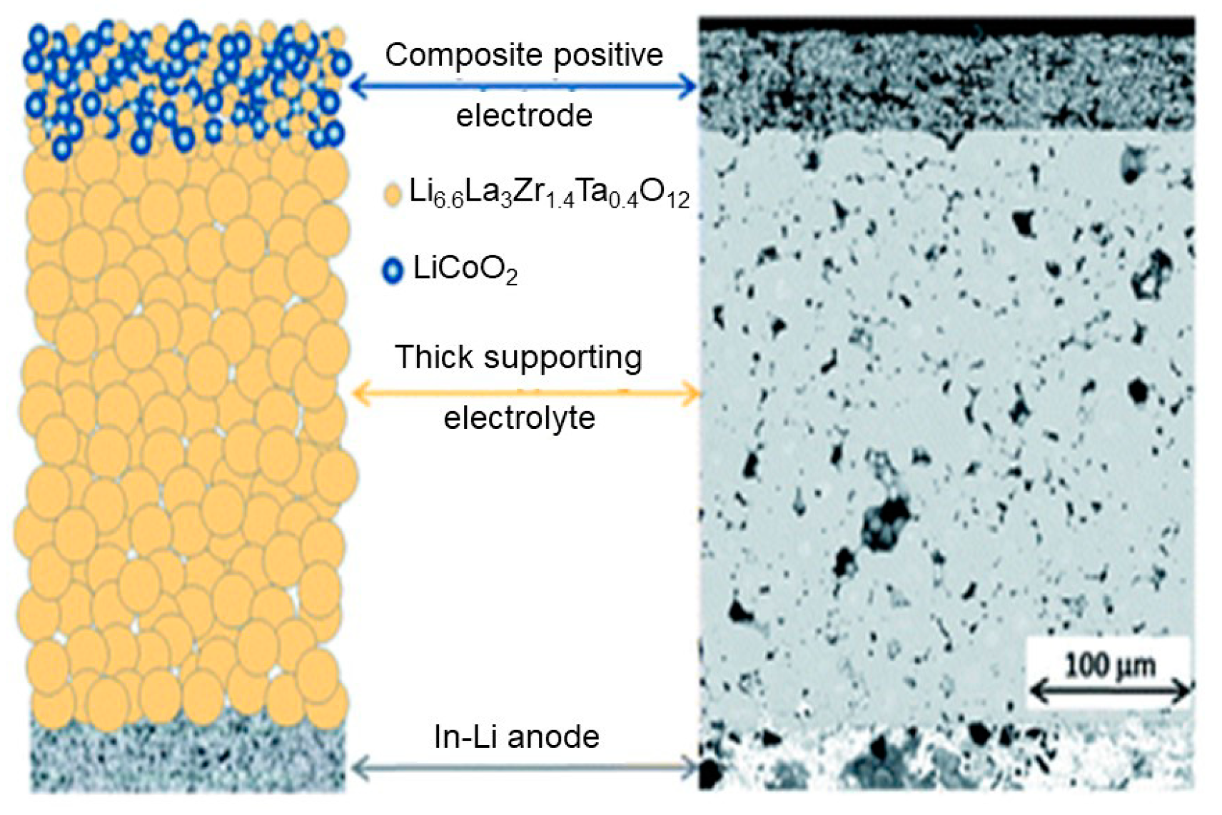
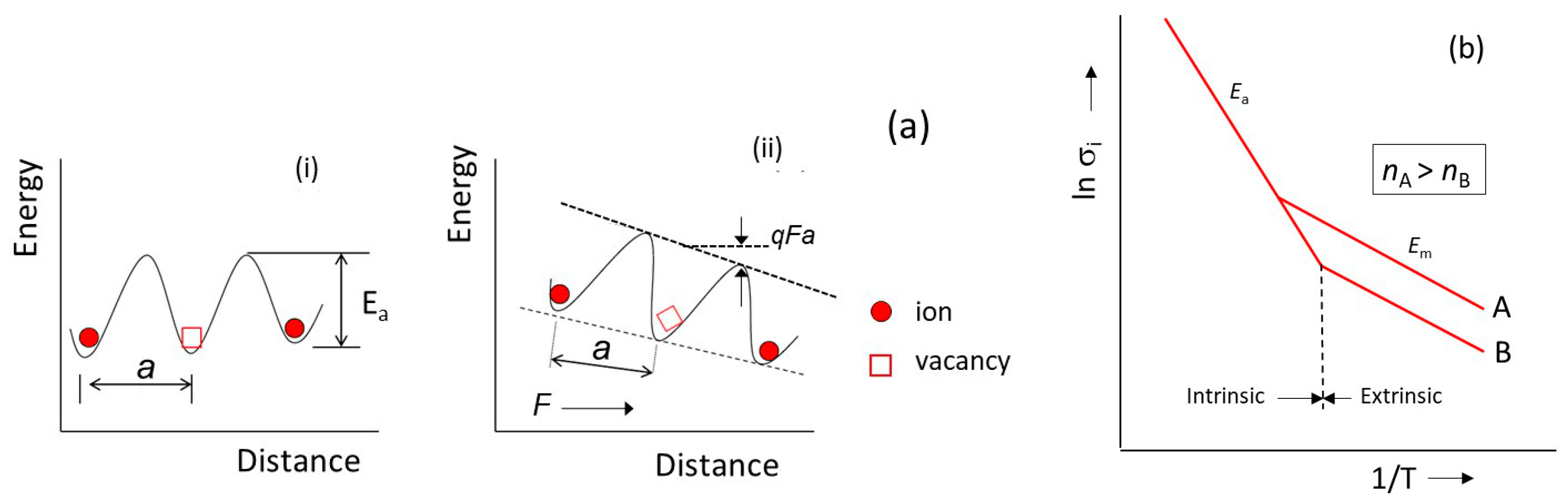
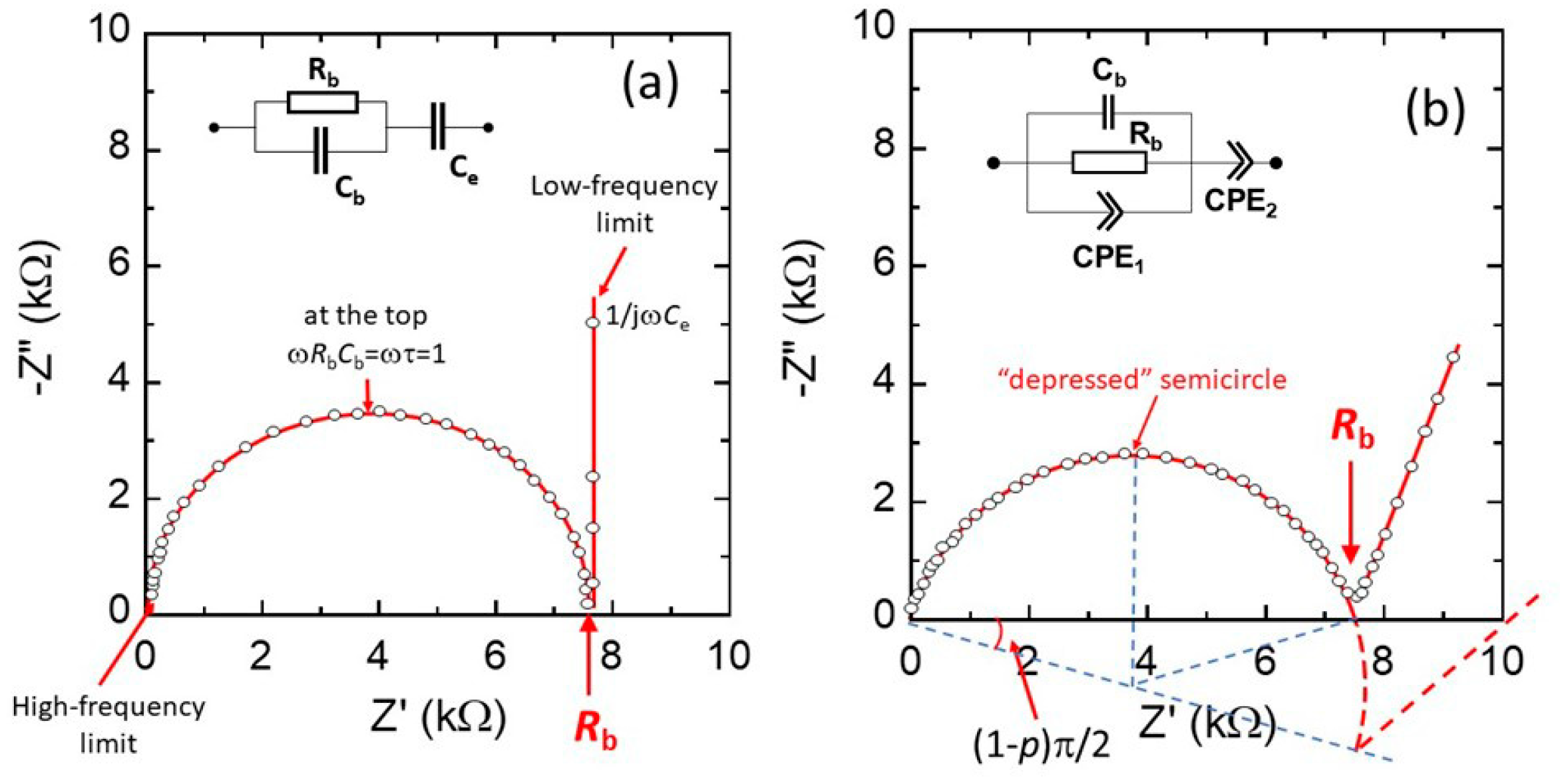
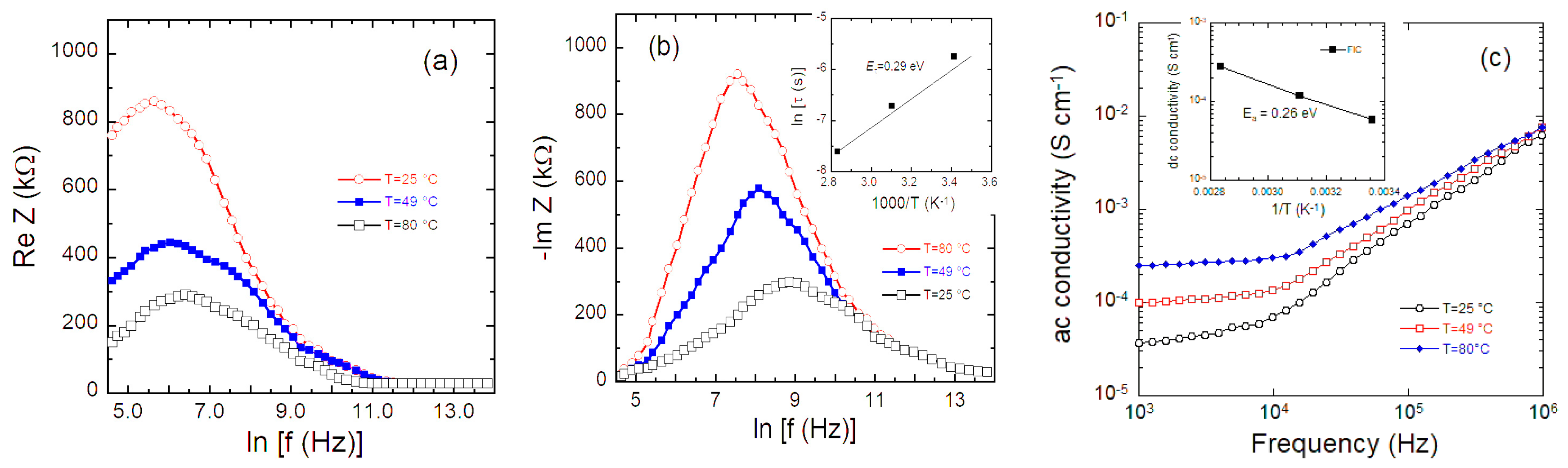
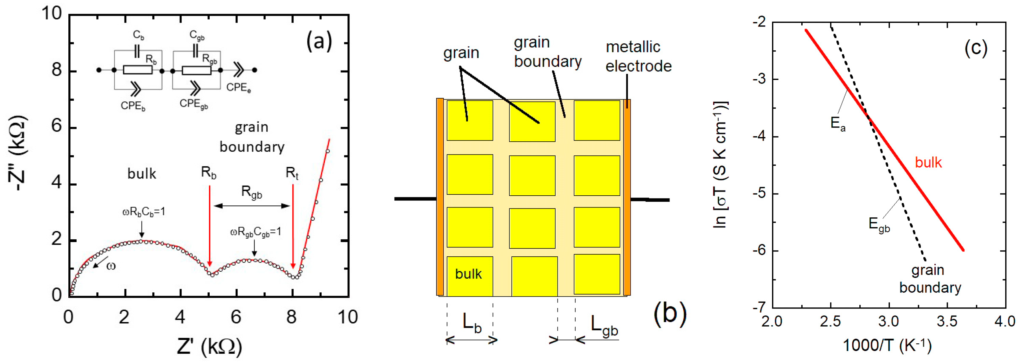
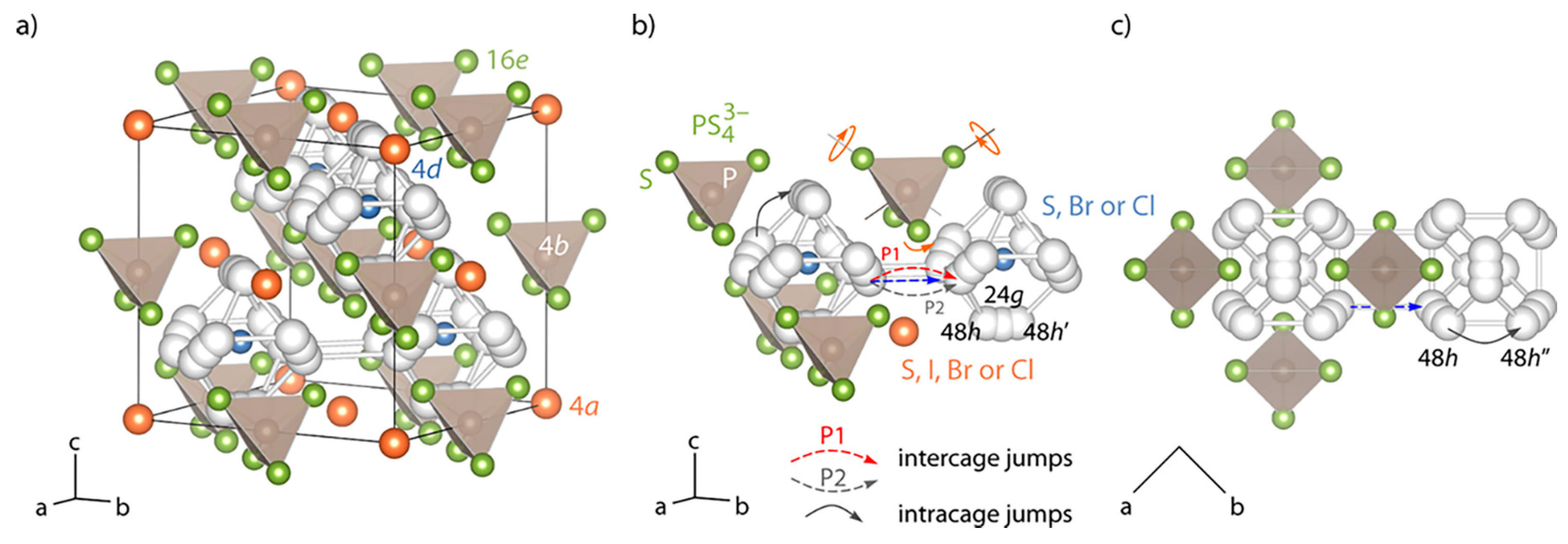
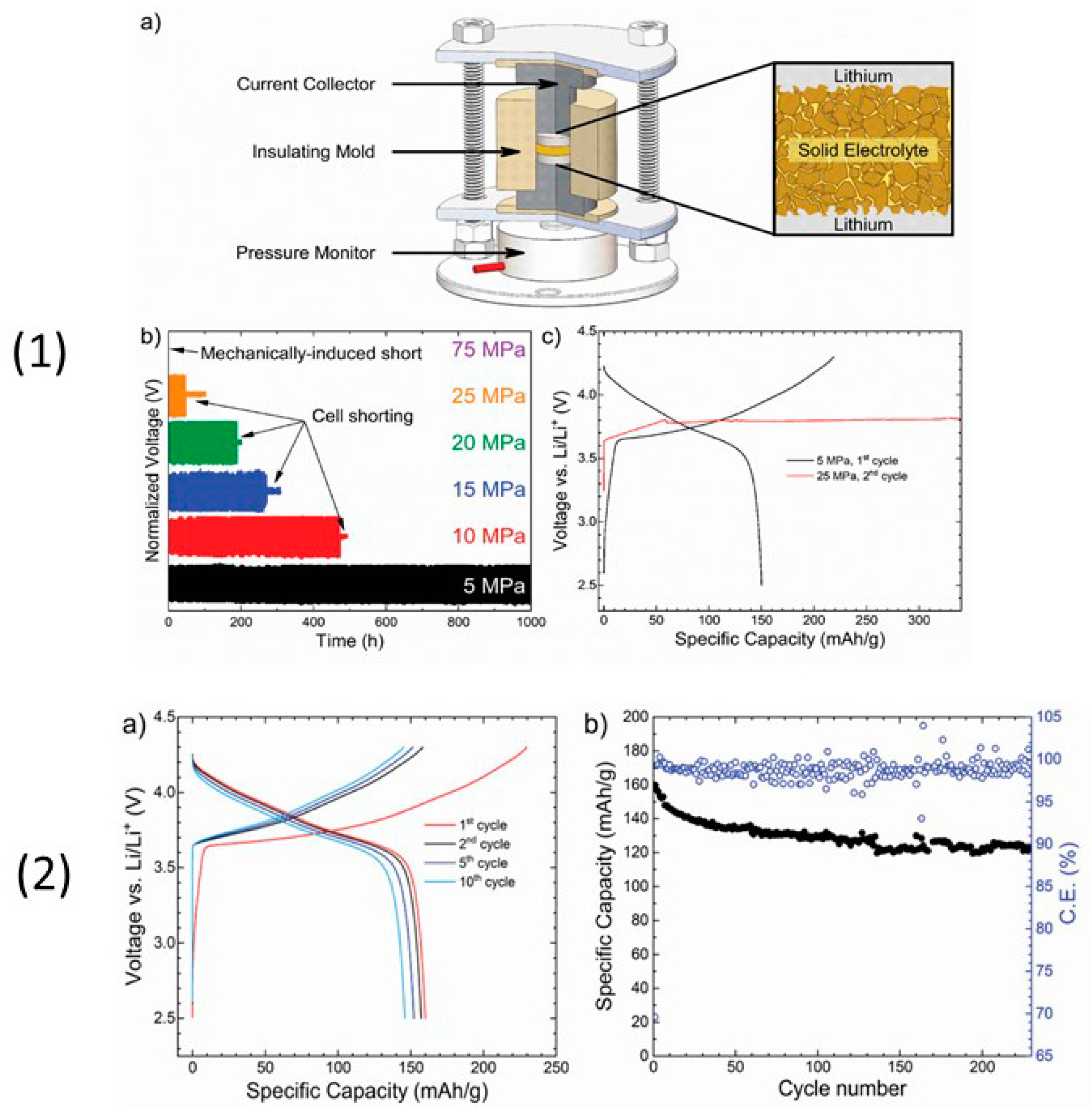
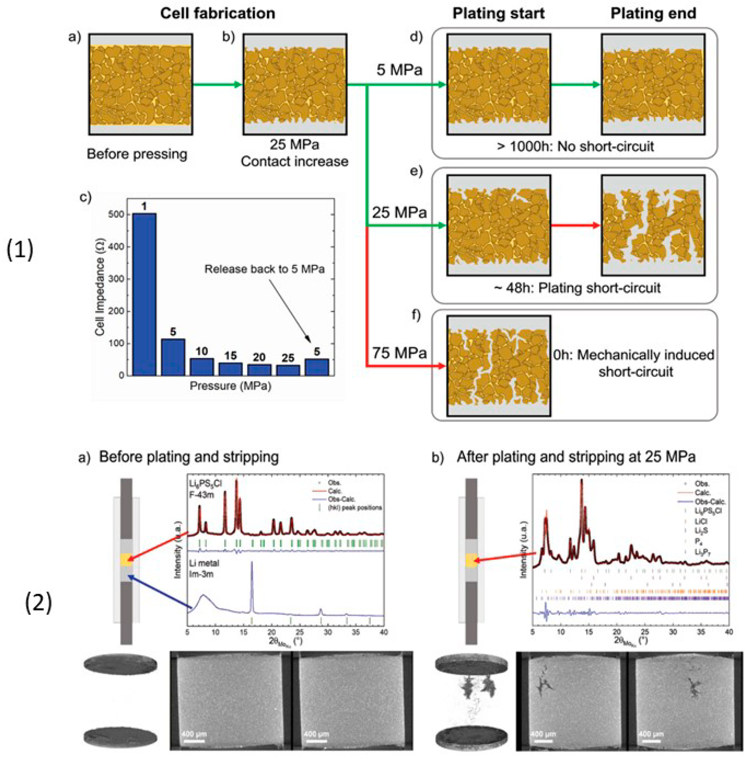
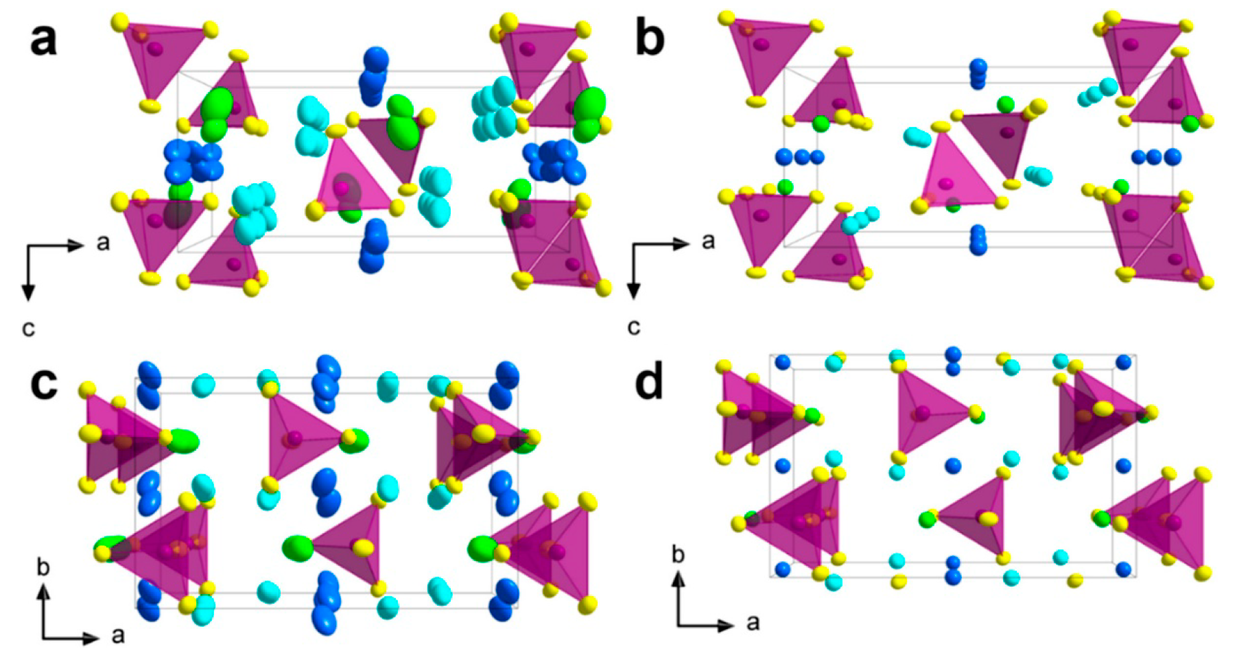
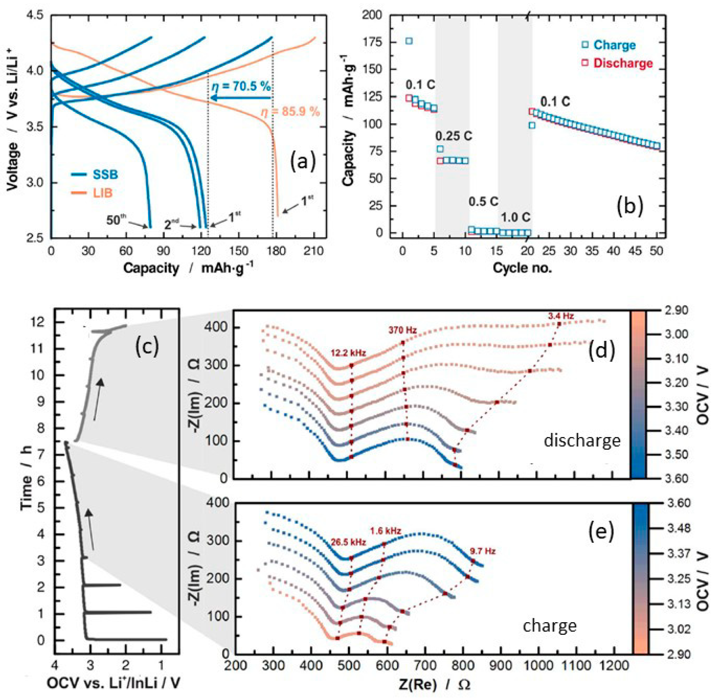
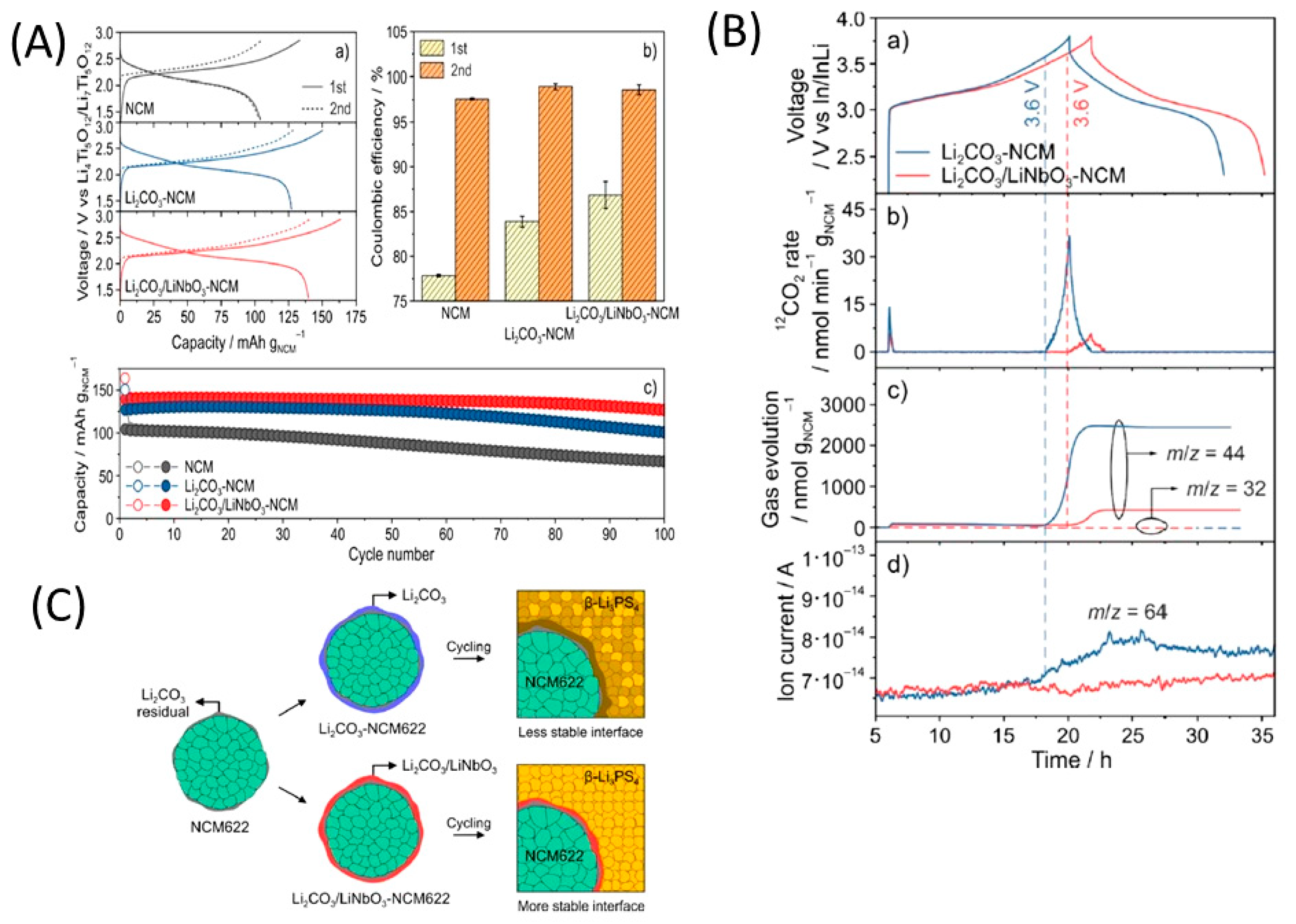
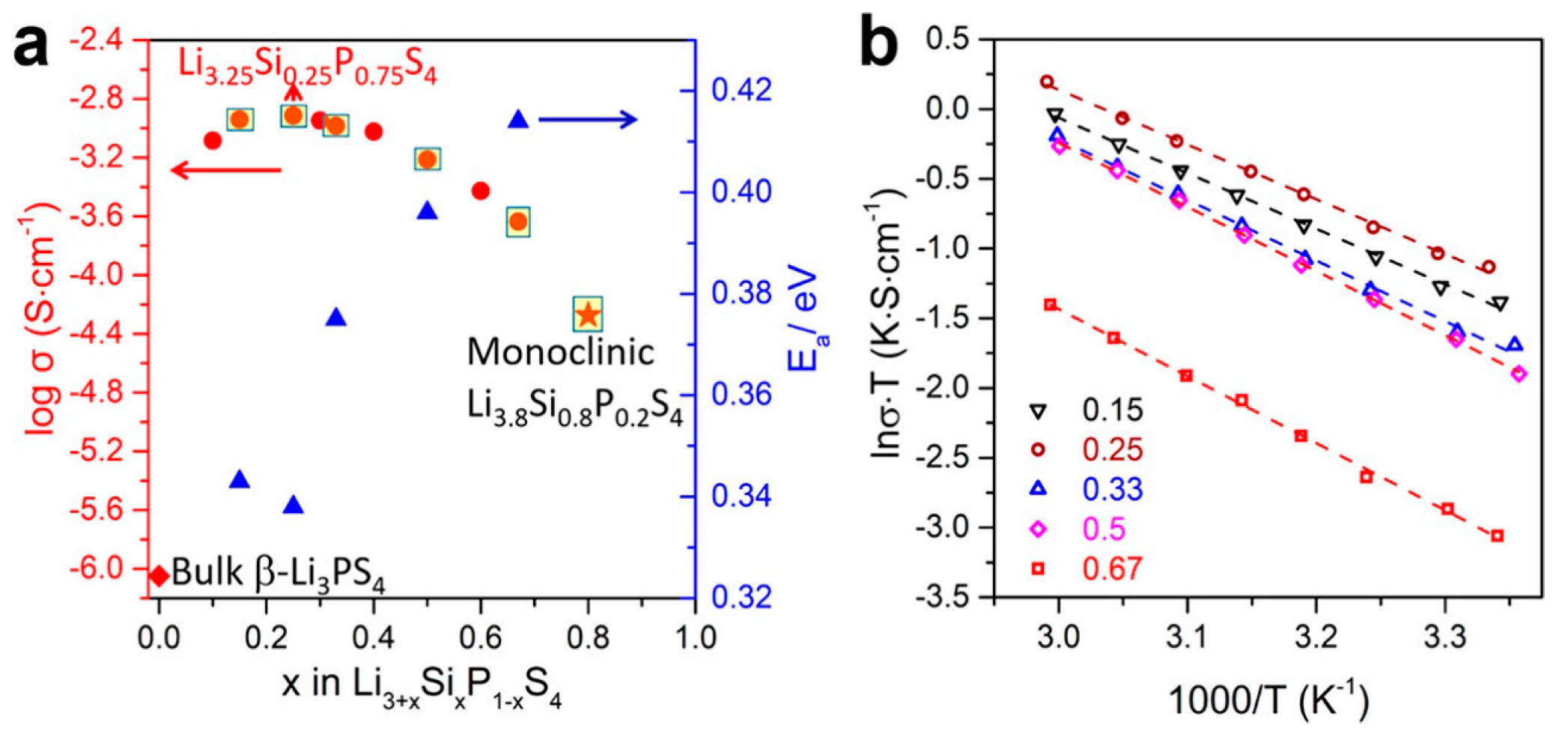
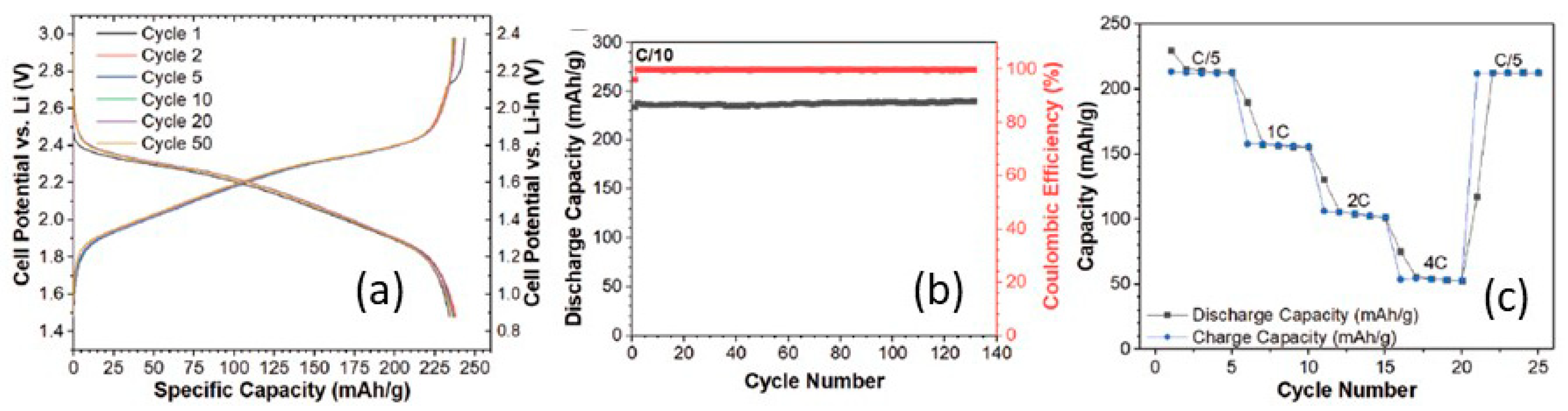
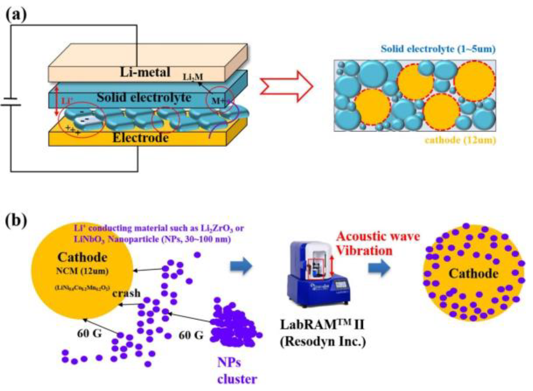
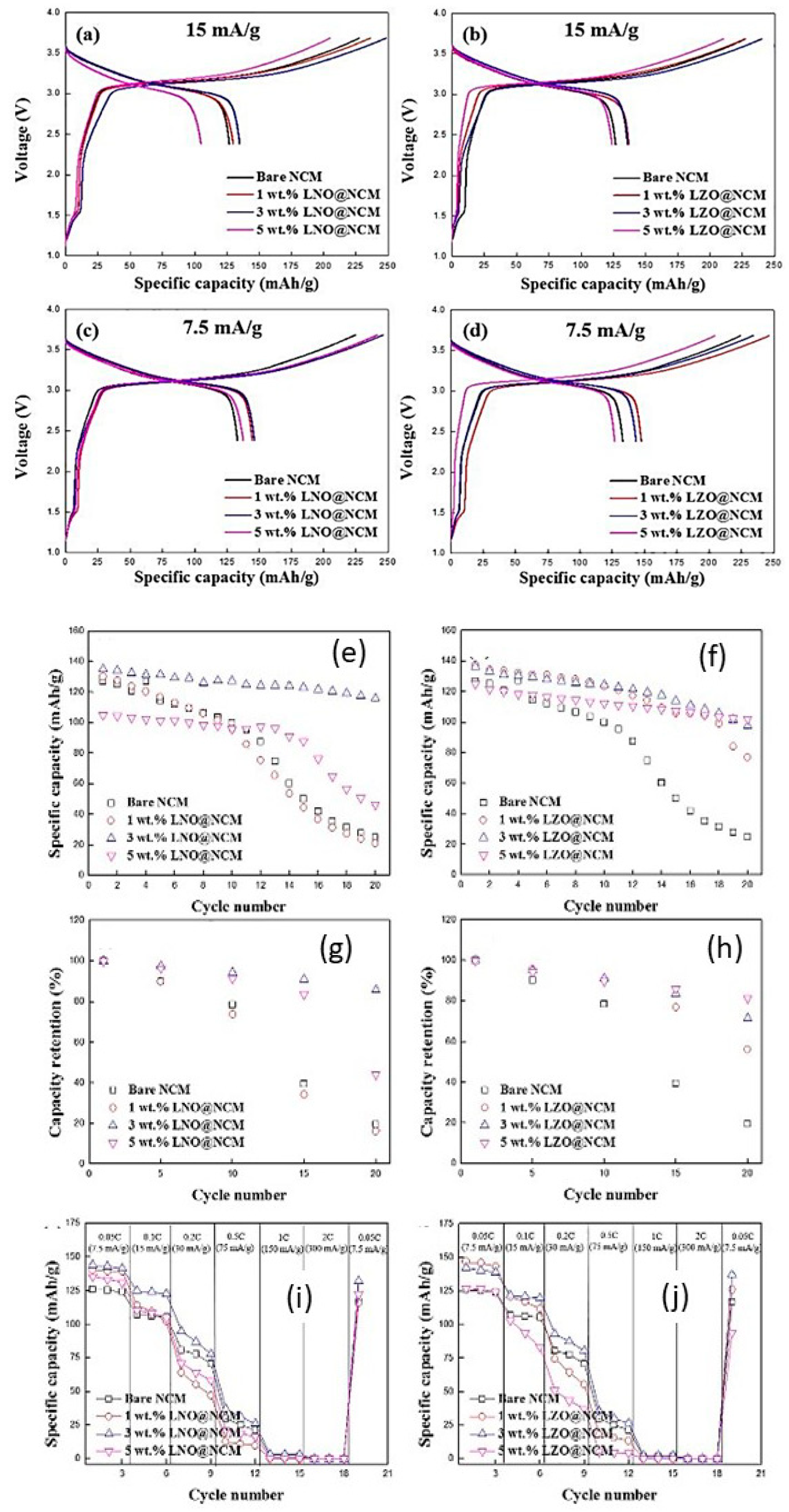
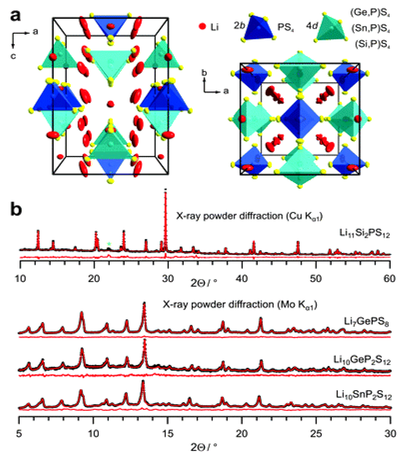
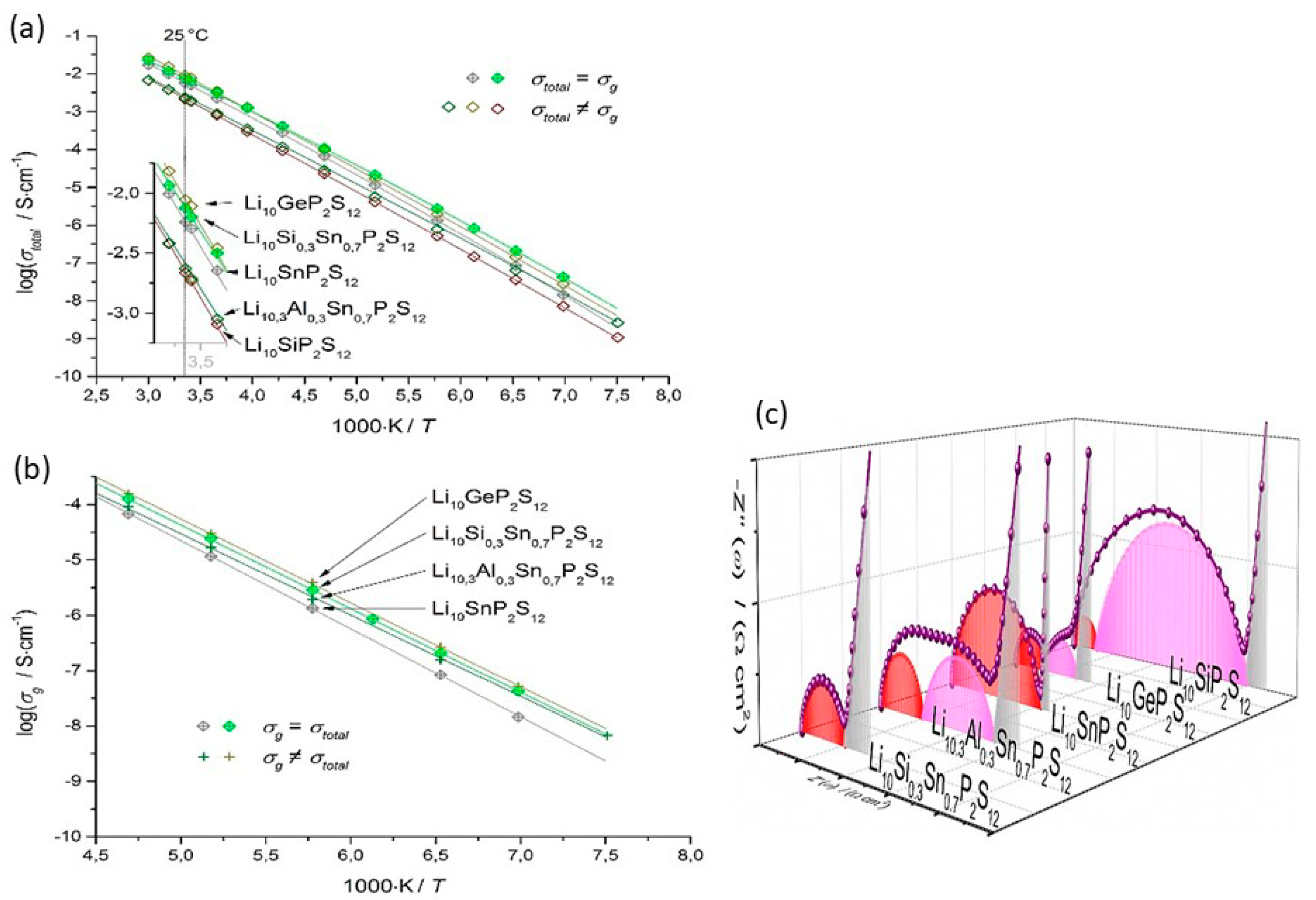
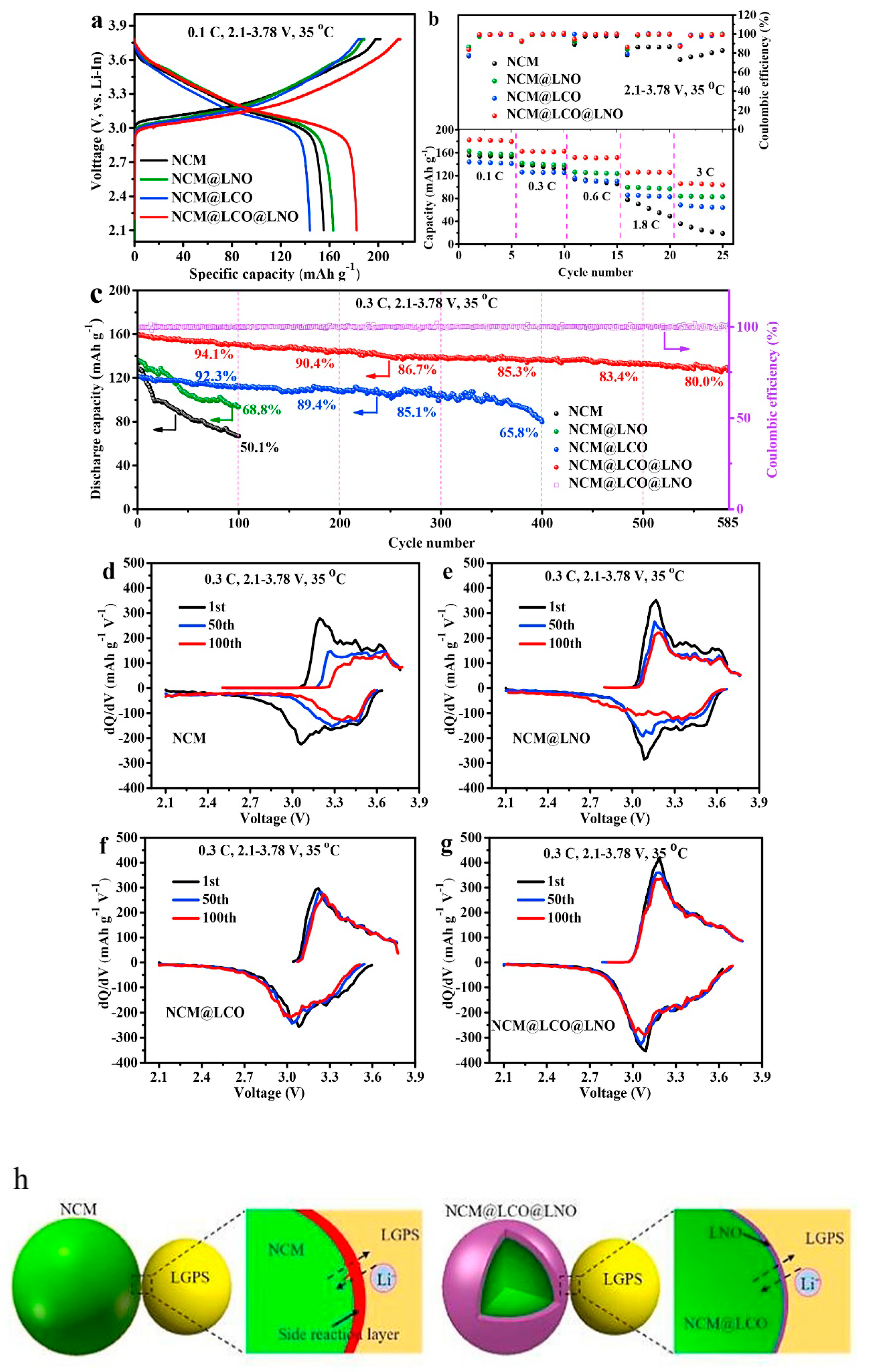
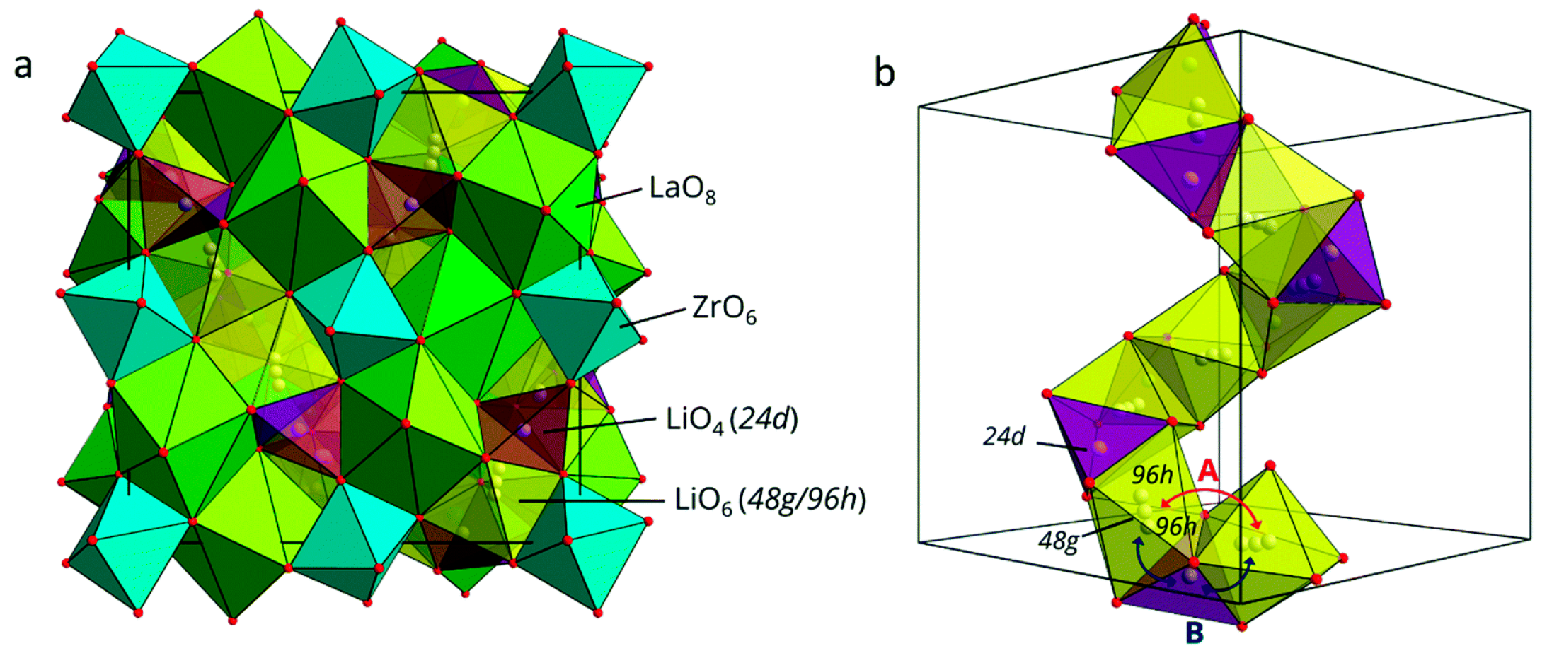
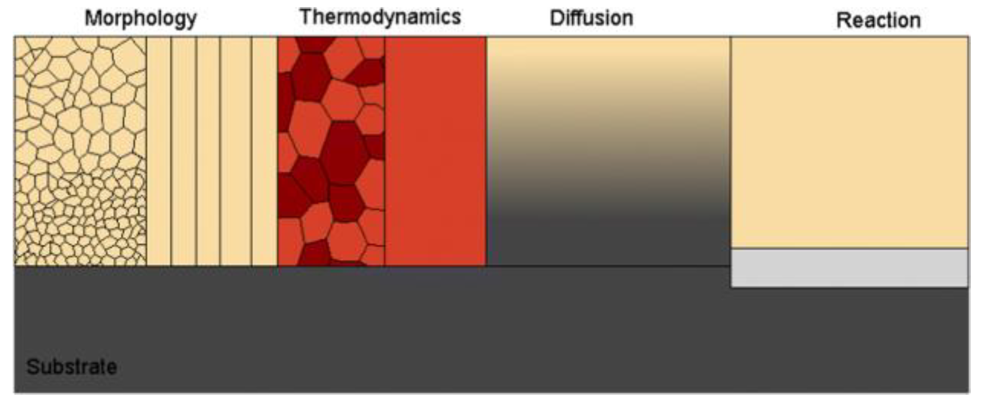
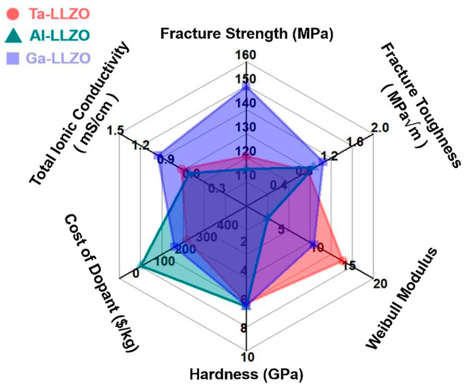
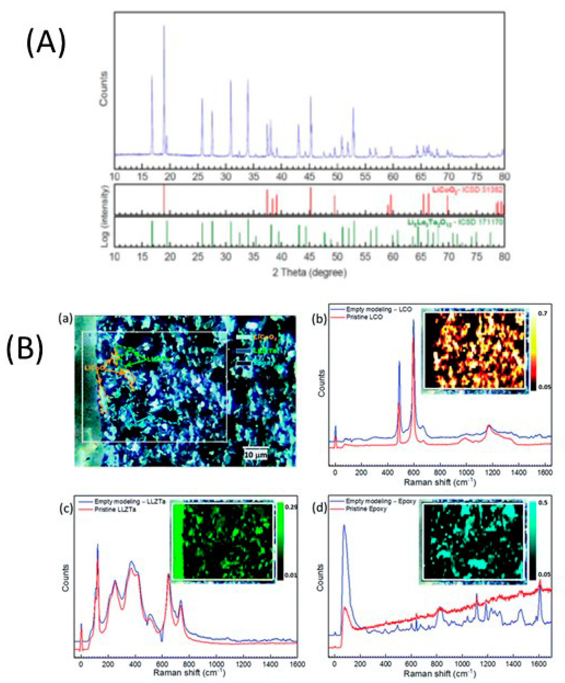
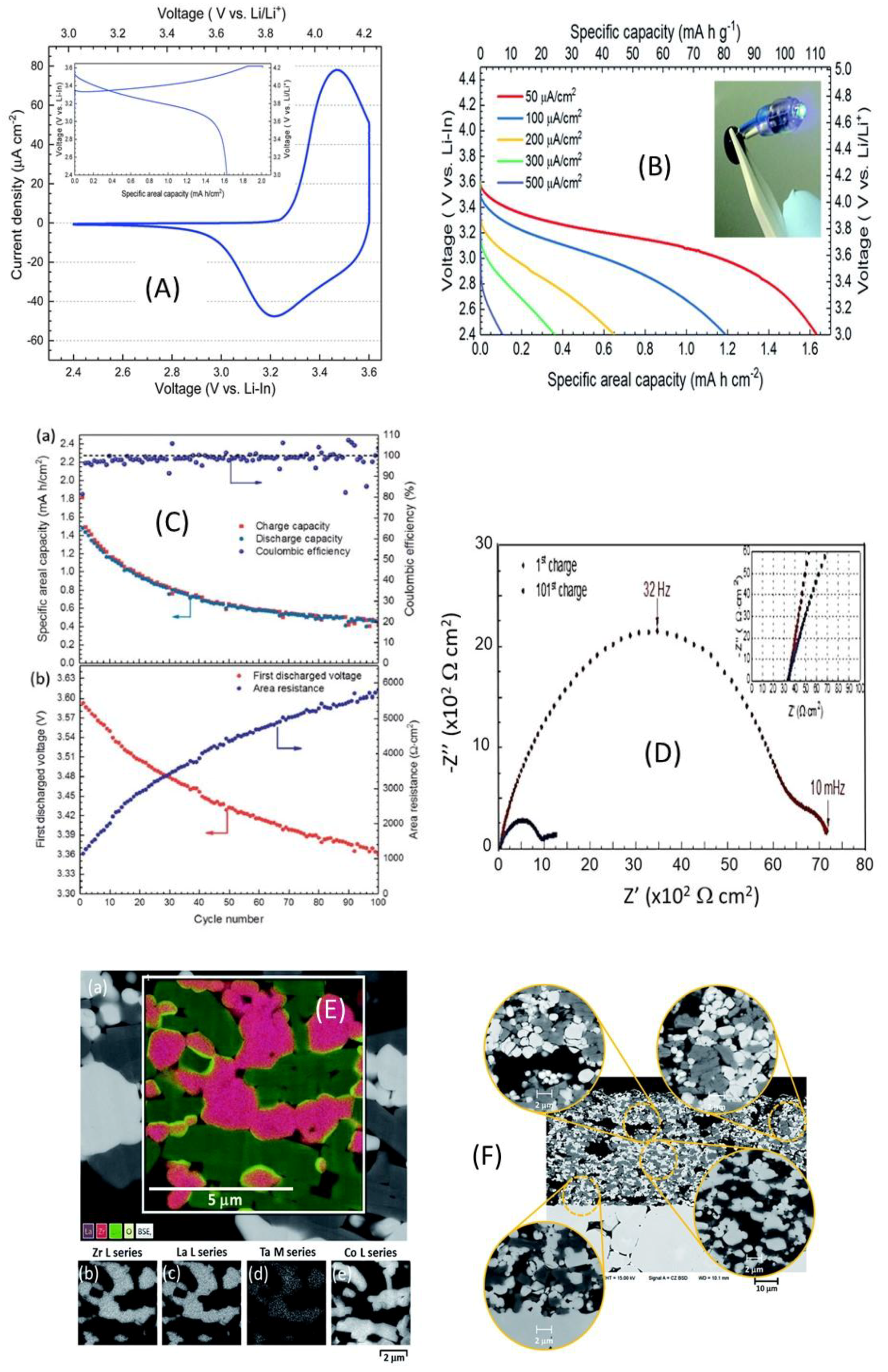
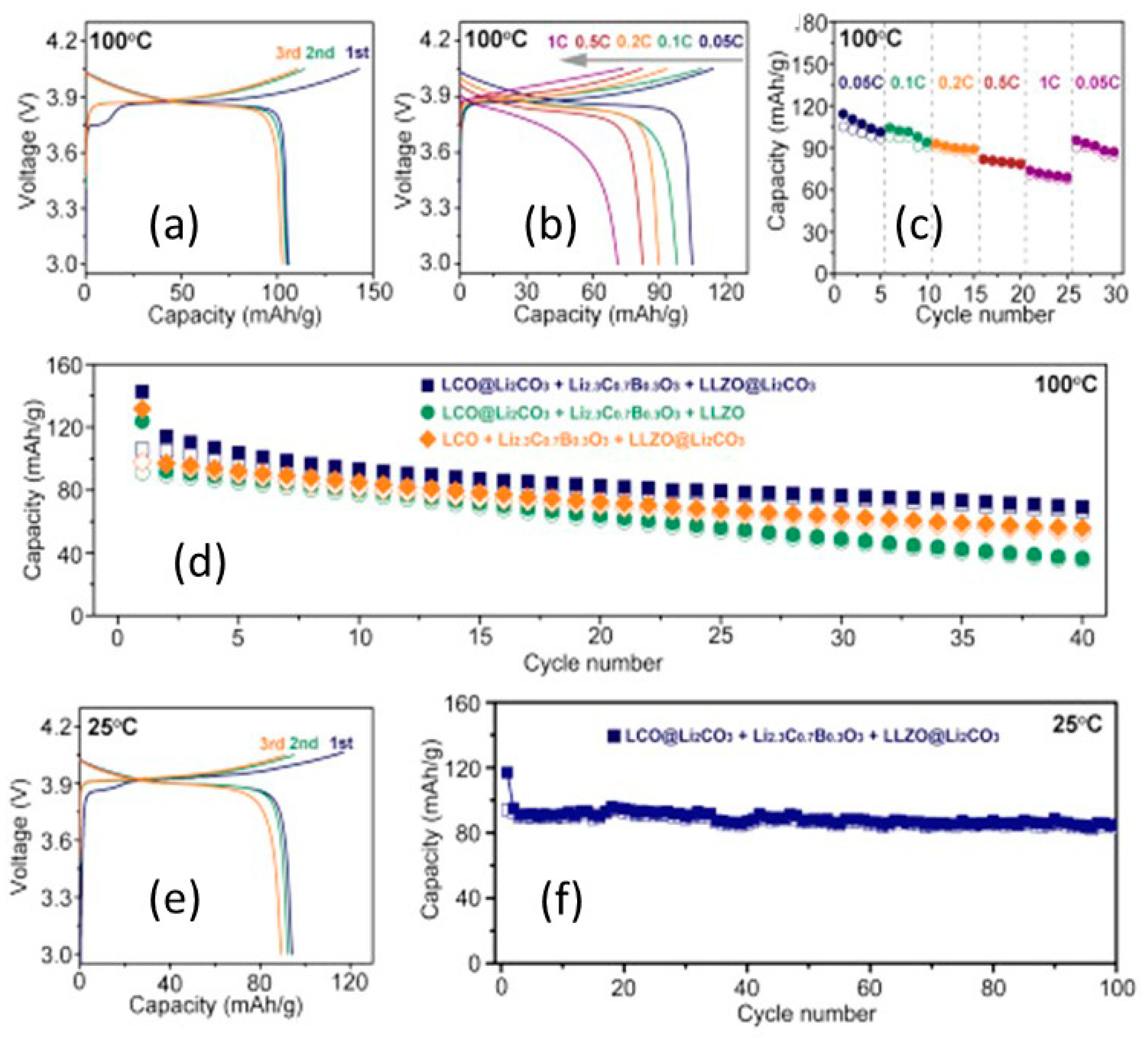
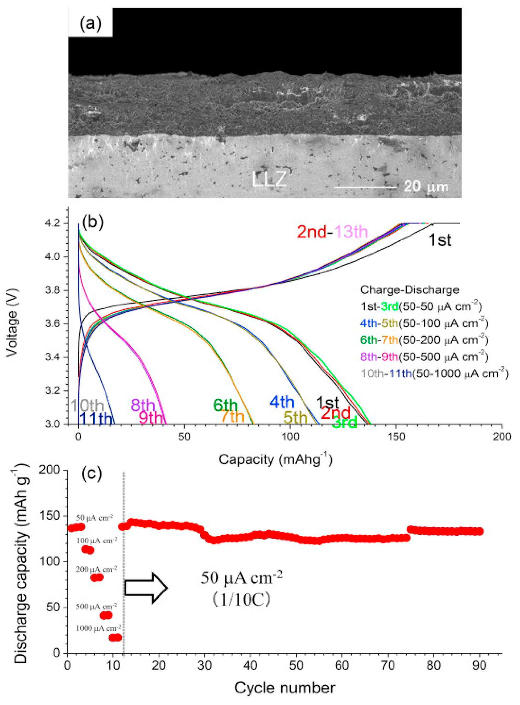
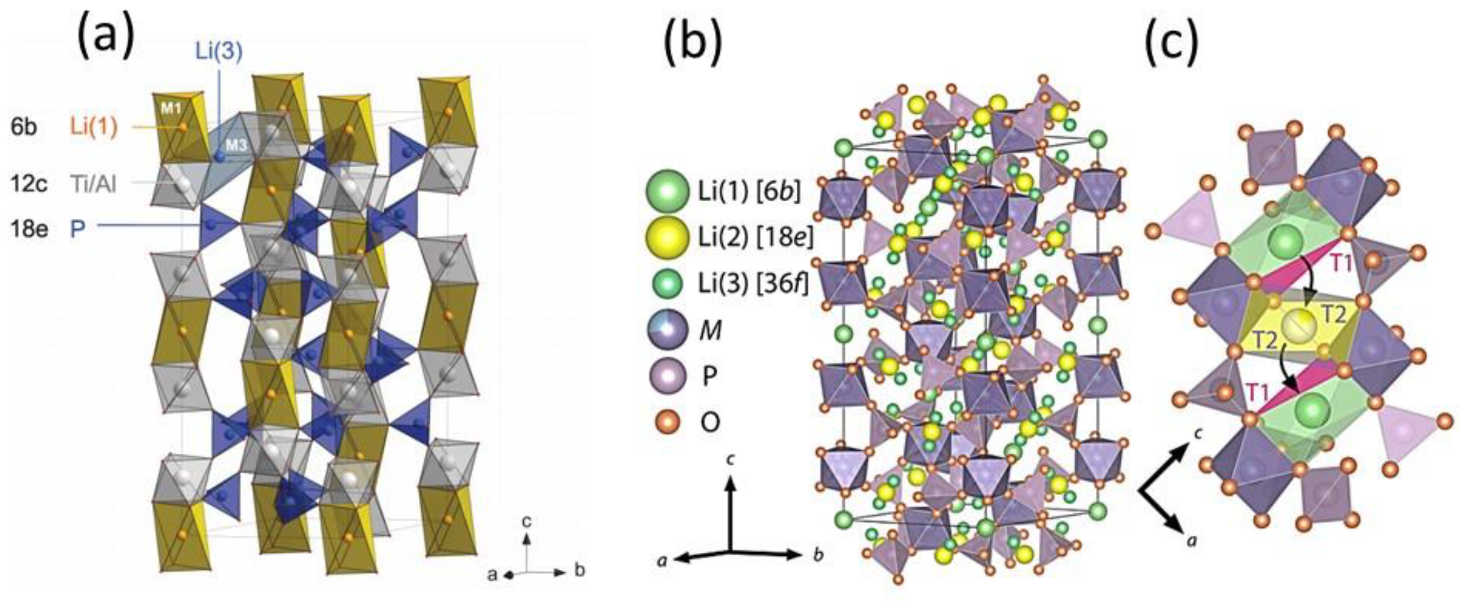
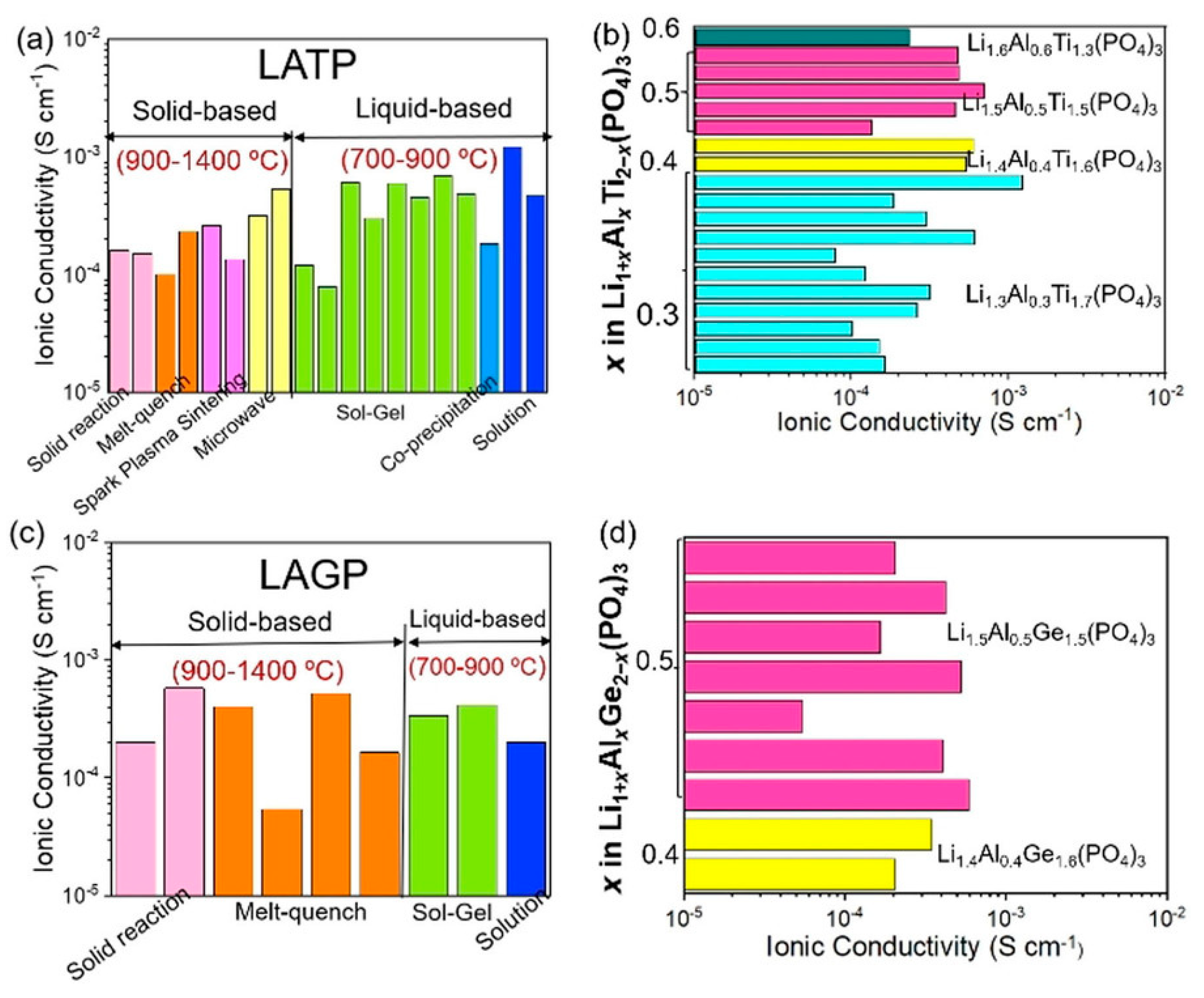
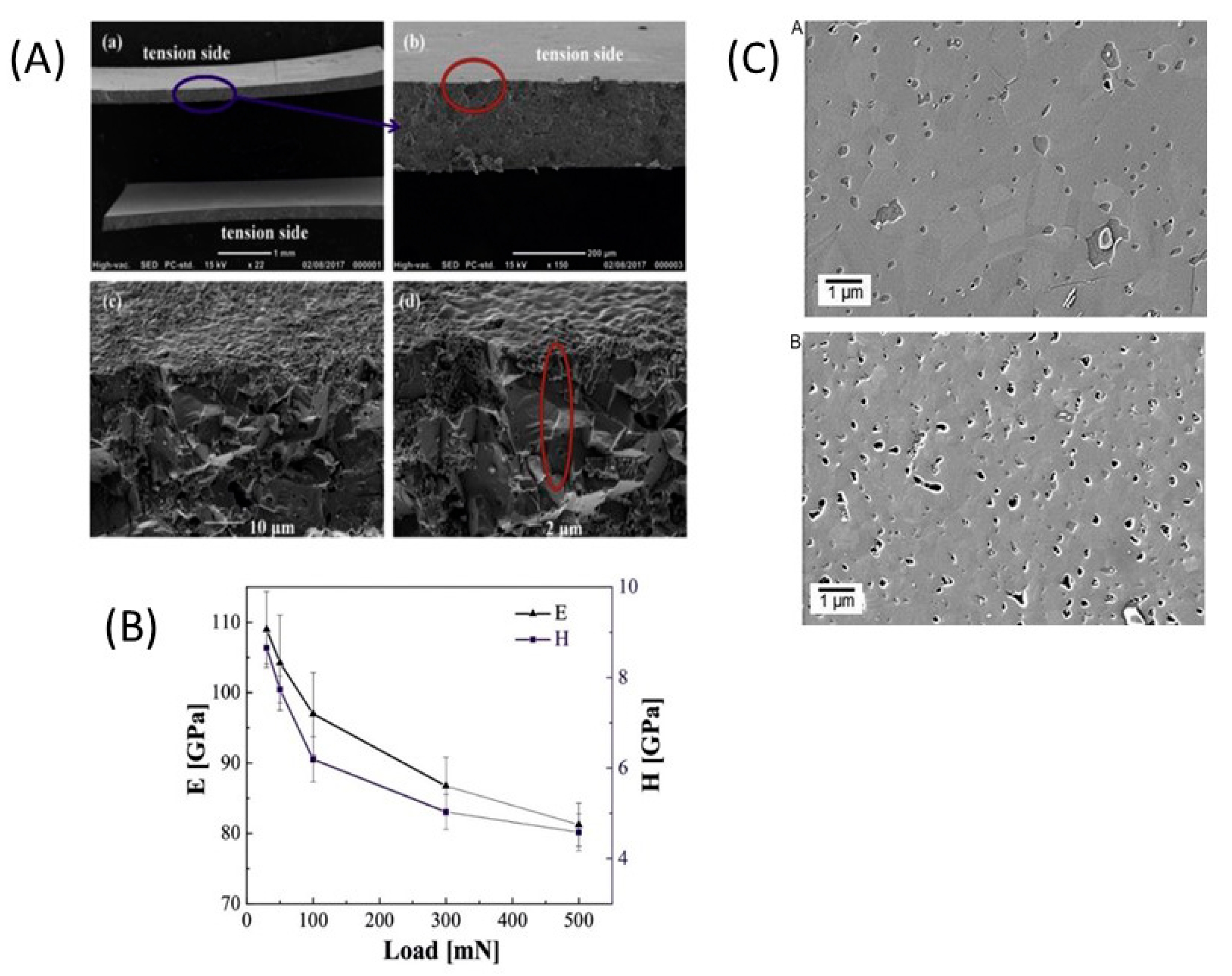
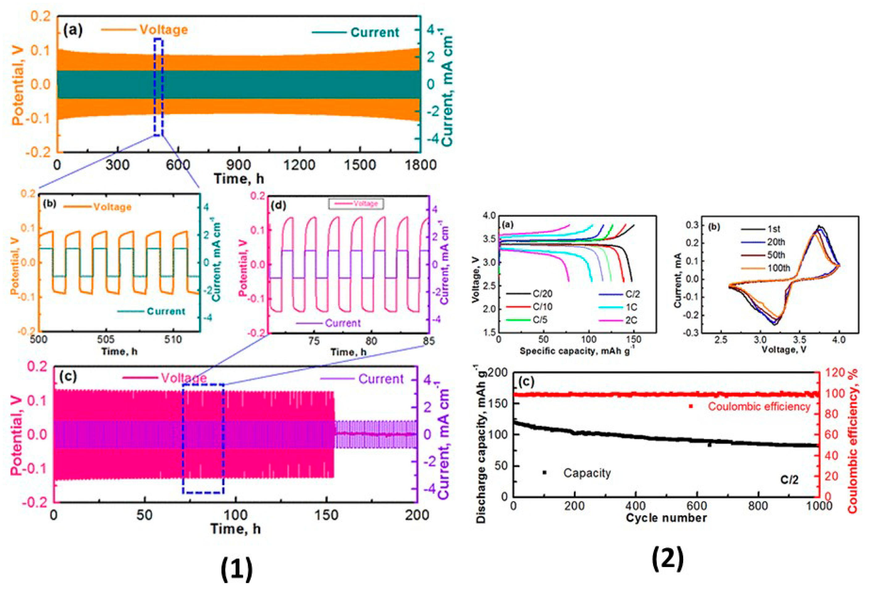
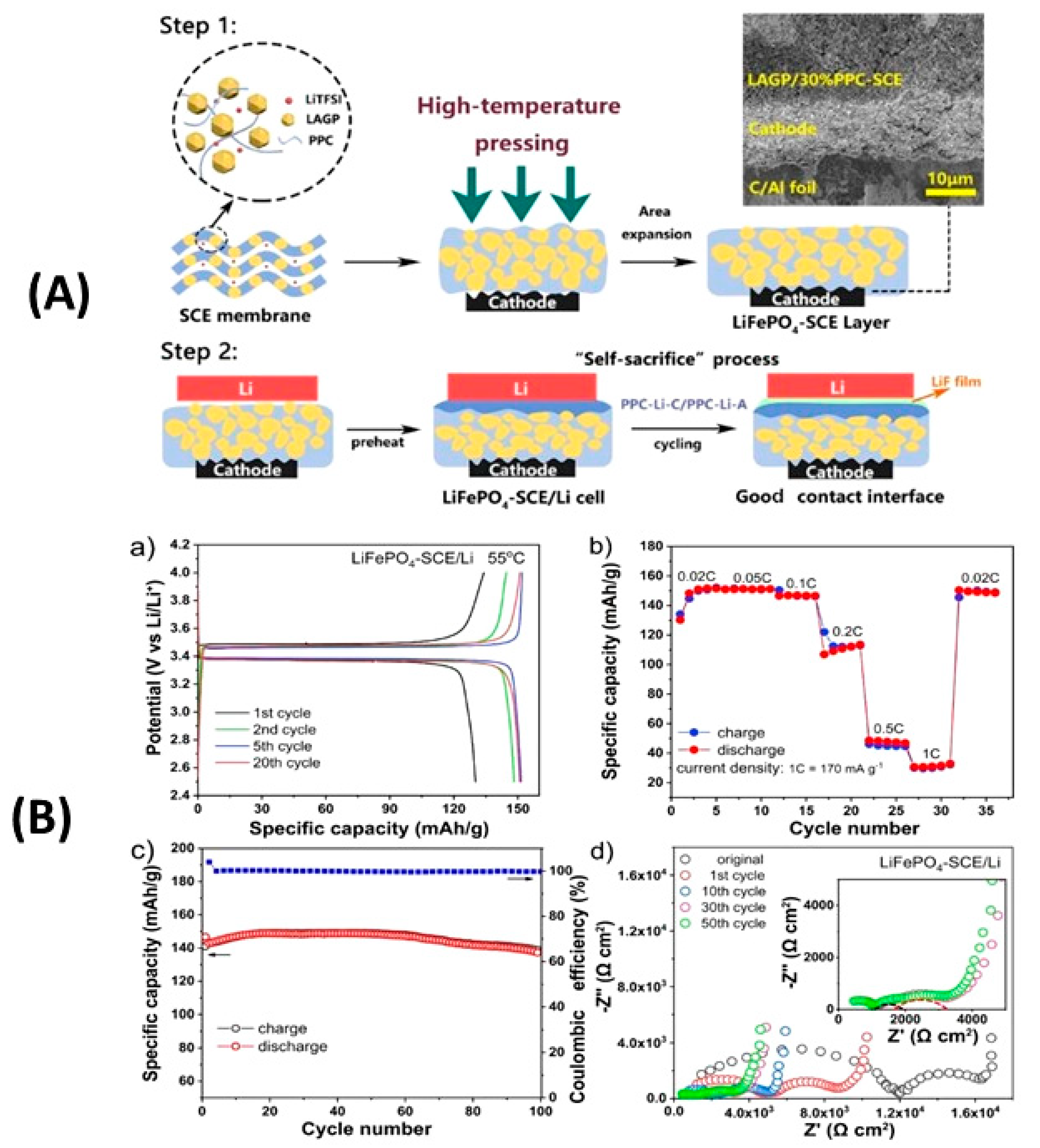
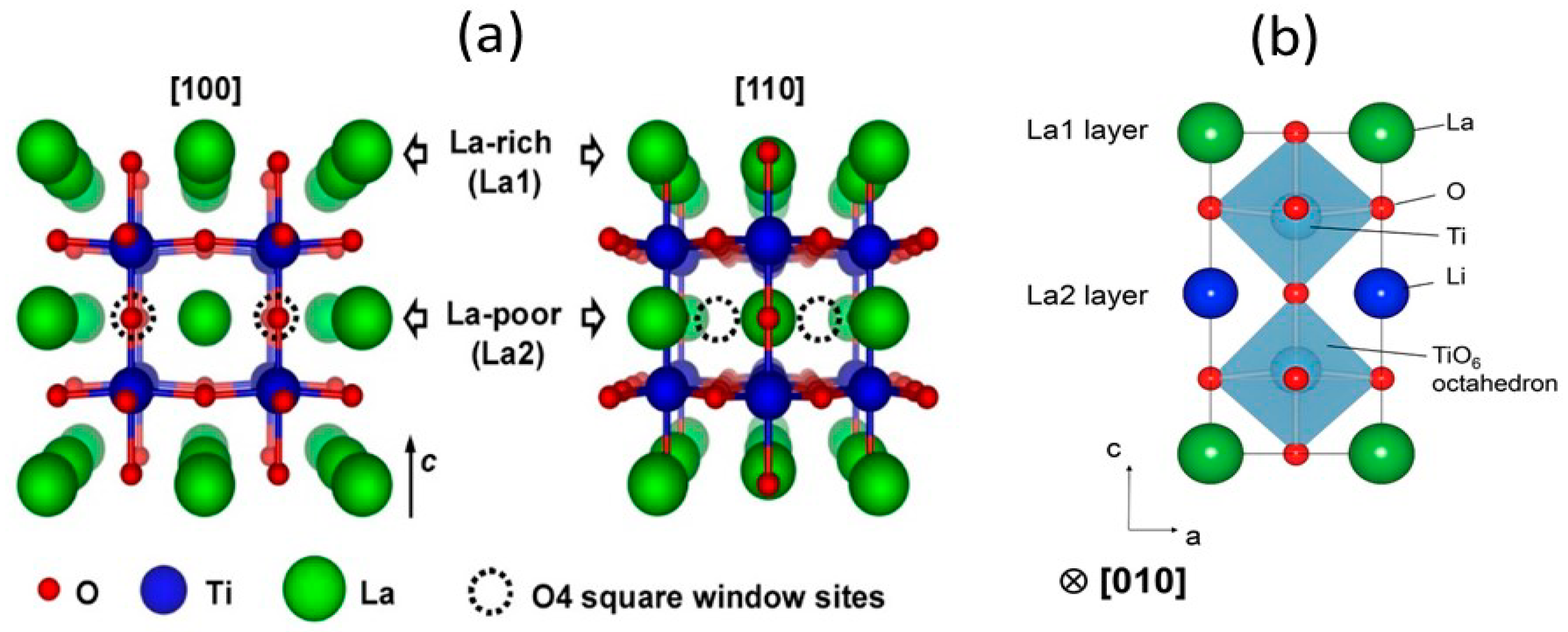
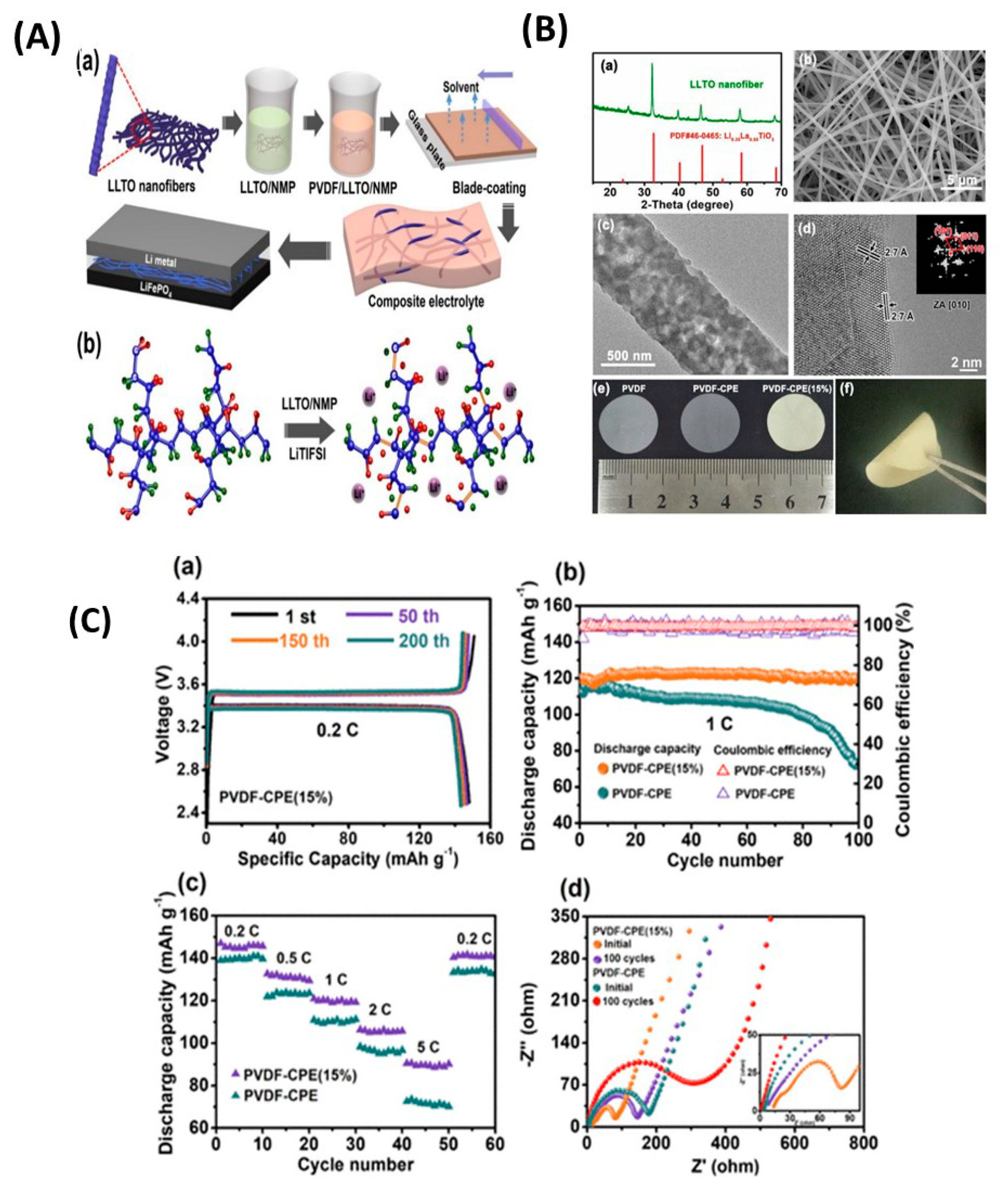
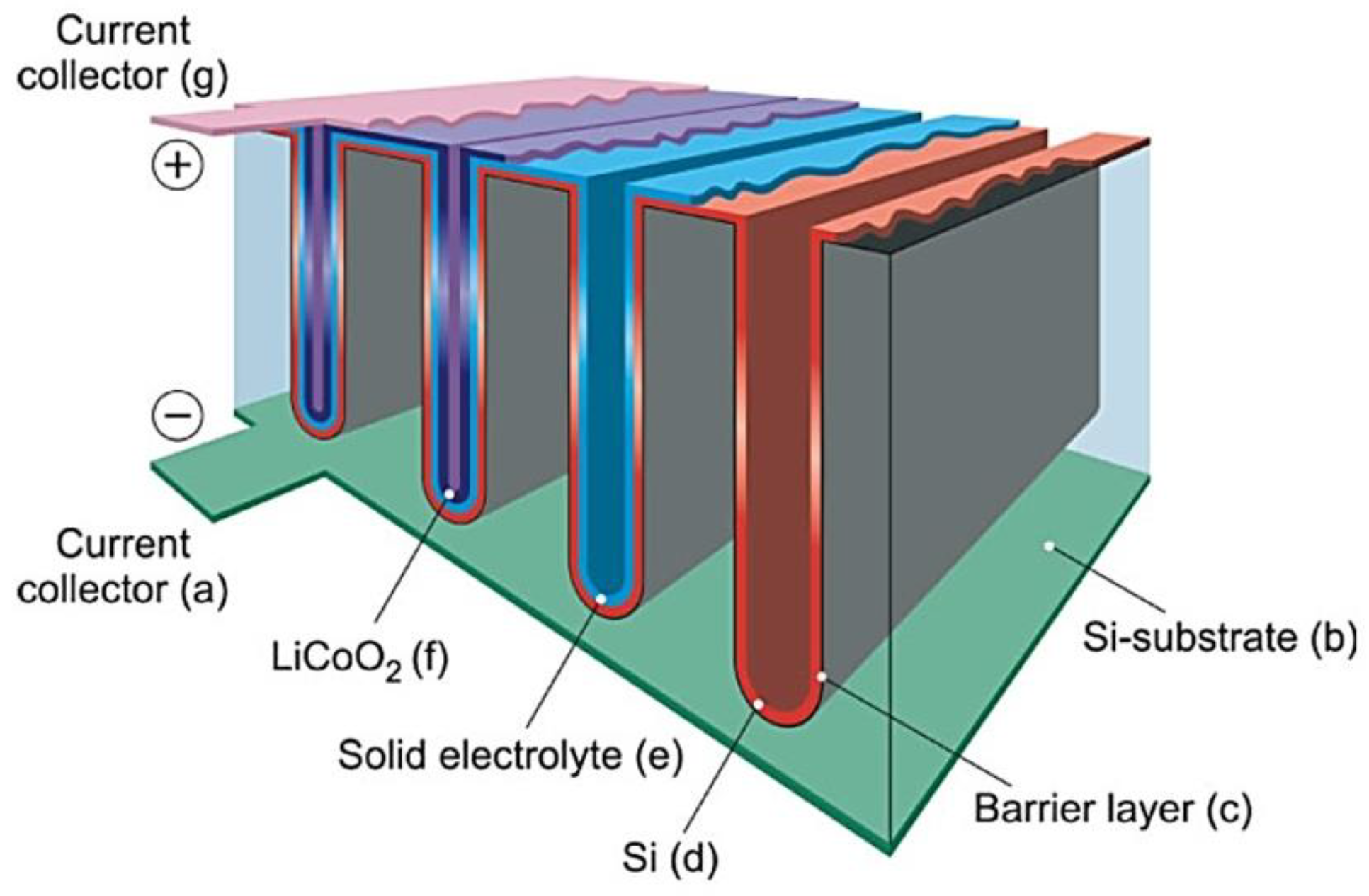
Figure 1. Schematic diagram of the fabricated electrolyte for all-solid-state Li batteries and its cross-sectional scanning electron micrograph. Reproduced with permission from [13]. Copyright 2018 Royal Society of Chemistry.
Nanomaterials 10 01606 g001
Figure 2. (a) Scheme of the potential barrier, which an ion has to overcome to exchange its site with a vacancy: (ii) Without external electric field and (ii) with external electric field. (b) Arrhenius plot of the ionic conductivity (ln σi vs. 1/T). The intrinsic and extrinsic regions are characterized by different Ea values.
Nanomaterials 10 01606 g002
Figure 3. (a) Nyquist impedance plot of an idealized fast-ionic conductor (FIC). The semicircle centered at Rb/2 represents the response of the Rb, Cb parallel element and straight line is the capacity of the electrolyte/electrode interface of impedance 1/jωCe. (b) Nyquist impedance plot of a FIC sample. The depressed semicircle reflects the combination of Rb, Cb, CPE1 and the inclined straight line represents the double-layer capacity of the inhomogeneous electrode surfaces.
Nanomaterials 10 01606 g003
Figure 4. (a) Plot of Re(Z) vs. ln (f). (b) Plot of -Im(Z) vs. ln (f) and (inset) determination of the activation energy Eτ of the relaxation time. (c) Frequency dependence of the ac conductivity and (inset) determination of the activation energy Ea of σdc.
Nanomaterials 10 01606 g004
Figure 5. (a) Impedance spectrum of a polycrystalline FIC. The equivalent circuit employed to fit the Nyquist plot is shown in inset. (b) Scheme of the” brickwork model” of intra- and intergrains in ceramic placed between two metallic electrodes for impedance measurements. (c) Typical Arrhenius curves of the conductivities for bulk and grain boundary showing increased intergain activation energy.
Nanomaterials 10 01606 g005
Figure 6. (a) Crystal structure of argyrodite-type Li6PS5X that crystallizes with cubic symmetry in the space group F43m. In Li6PS5Cl, the Li+ ions solely occupy the 24g positions of the split site 48h−24g−48h′. In compounds with X = Br and I, they are distributed over the 24g sites and the 48h positions. P resides on 4b. The 16e is fully occupied by S2− forming PS43− tetrahedra. Whereas in Li6PS5I, the halide anions occupy only the 4a sites; in Li6PS5Br, the occupation factors, according to neutron diffraction, amount to 78% (4a) and 22% (4d). For Li6PS5Cl, the occupation factors are 39% (4a) and 62% (4d); thus, the majority of the Cl anions occupy the inner centers of the Li cages, which are too small for I. (b) Intracage and intercage Li diffusion pathways: Hopping between two Li cages (48h−48h″, see also (c)), either following a direct or curved pathway, could be influenced by S2− anions of a nearby PS43− tetrahedral. The jump distance depends on the lattice constant and, thus, on halogen substitution. Possible rotational jumps are indicated that may open or block the Li+ pathway. (c) The same cutout as in (a) but viewed along the c-axis. Two S2− anions of the PS43− tetrahedra are located slightly above the direct 48h−48h″ exchange pathway. Rotational jumps of the PS43− tetrahedra could also influence the intracage jumps. Reproduced with permission from Ref. [179]. Copyright 2019, American Chemical Society.
Nanomaterials 10 01606 g006
Figure 7. (1) (a) Design of solid-state Li symmetric cell that allows control and monitoring of the pressure during cycling. (b) Normalized voltage of Li symmetric cells as a function of the plating and stripping times at different stack pressures. At 75 MPa, the cell already mechanically short-circuited before cycling began. At 5 MPa, no short-circuit was observed for over 1000 h. (c) Voltage profile of a full cell with Li metal anode. The first cycle was run at a stack pressure of 5 MPa. The stack pressure was subsequently increased to 25 MPa before the second cycle, during which the cell short-circuited. (2) (a) Voltage profiles of the 1st, 2nd, 5th, and 10th cycles and (b) cycle life of a Li metal|Li6PS5Cl|LiNbO3-coated LiNi0.8Co0.15Al0.05O2 all-solid-state Li-ion battery cycled at C/10 and a stack pressure of 5 MPa (black and blue dots are specific capacity and coulombic efficiency data, respectively). No short-circuiting behavior was observed. The average Coulombic efficiency (C.E.) over 229 cycles was 98.86%, and the capacity retention of the cell was 80.9% over 100 cycles. The active material loading was 3.55 mg cm−2. Reproduced with permission from [201]. Copyright 2020 Wiley.
Nanomaterials 10 01606 g007
Figure 8. (1) Schematic of the effect of the stack pressure on the short-circuiting behavior of Li metal solid-state batteries. (a) During cell fabrication, the contact between the electrolyte and Li metal was poor before the Li metal was pressed on the electrolyte pellet. (b) Pressing the Li metal at 25 MPa allowed the proper wetting of the electrolyte and (c) induced a large decrease in the impedance of the symmetric cell even when the pressure was later decreased to 5 MPa. (d) Plating and stripping at a stack pressure of 5 MPa. Li did not creep inside the solid-state electrolyte (SSE) pellet, and therefore, the cell cycled for more than 1000 h. (e) At a stack pressure of 25 MPa, Li slowly crept between the grains of the SSE and plating occurred on the dendrites, which eventually short-circuited the cell after 48 h. (f) When the stack pressure was too high, Li crept through the electrolyte and formed dendrites that mechanically short-circuited the cell. (2) Schematic of the cell used for X-ray tomography and X-ray diffraction (XRD) analyses; profile matching of the XRD and X-ray tomography patterns of a Li|Li6PS5Cl|Li symmetric cell cycled under a stack pressure of 25 MPa (a) before plating and stripping and (b) after short-circuiting. Before plating and stripping, only Li6PS5Cl was detected in the electrolyte and Li metal was present on both sides. The X-ray tomography pictures confirmed that Li was not present in the electrolyte. After the cell short-circuited, several additional phases, mainly Li2S, LiCl, P4, and Li3P7, were detected inside the electrolyte; these were components of the solid electrolyte interphase that formed when Li was in contact with Li6PS5Cl. The X-ray tomography pictures illustrate that a large quantity of low-density dendrites formed in the electrolyte. Reproduced with permission from [201]. Copyright 2020 Wiley.
Nanomaterials 10 01606 g008
Figure 9. (a) Schematic representation of the structure of orthorhombic Li3.25[Si0.25P0.75]S4 derived from single-crystal data. (b) Structure of β-Li3PS4 (β-LPS) along the [010] direction. Views of (c) Li3.25[Si0.25P0.75]S4 and (d) β-LPS along the [001] direction. Here, the violet tetrahedra, turquoise spheres, Li(8d)-2 (blue) in Li3.25[Si0.25P0.75]S4/Li(4b)-2 (blue) in β-Li3PS4, green spheres, and yellow spheres denote Li(4c)-3A/B, and S atoms, respectively. Reproduced with permission from [222]. Copyright 2019 American Chemical Society.
Nanomaterials 10 01606 g009
Figure 10. (a) Representative charge–discharge profiles of an ASSLB for the 1st, 2nd, and 50th cycle (blue). The ASSLB was cycled between 2.7 and 4.3 V vs. Li+/Li. The orange curve represents the 1st charge-discharge cycle of a liquid Li-ion battery (LIB) with NMC-811 as the cathode, and it was included for comparison. The current density for all cycles was 0.1C. (b) Rate test and long-term cyclability of the SSB at the current densities of 0.1, 0.25, 0.5, and 1C, followed by open-end cycling at 0.1C. A large first cycle capacity loss was observed for the ASSLB, which did not occur for the LIB. Impedance spectra recorded intermittently during galvanostatic battery cycling. (c) First cycle charge and discharge profile of a Li–In|β-Li3PS4|NCM811/β-Li3PS4 cell at 0.1 C showing current interruption corresponding to the periods of impedance measurement. Impedance spectra during (d) charge and (e) discharge periods. Measurements were conducted after 1 h of charging or discharging, respectively. Spectra are stacked with an offset of 40 Ω in the −Im(Z) direction. Reproduced with permission from [203]. Copyright 2017 American Chemical Society.
Nanomaterials 10 01606 g010
Figure 11. (A) (a) The 1st and 2nd cycle voltage profiles, (b) corresponding Coulombic efficiencies, and (c) cycling performance at a rate of C/10 and 25 °C of solid-state batteries (SSBs) using bare (gray), Li2CO3-coated (blue), and Li2CO3/LiNbO3-coated NMC622 (red) cathodes. In (b), the error bars indicate standard deviations. (B) (a) The 1st cycle voltage profile at a rate of C/20 and 45 °C of SSBs using Li2CO3-coated (blue) and Li2CO3/LiNbO3-coated NMC622 (red) cathodes. (b) The CO2 mass signals (m/z = 44) and (c) cumulative amounts. (d) Time-resolved ion current for the evolution of SO2 (m/z = 64). (C) Illustration of different interfacial reactivities of the Li2CO3-coated (indicated by the oxidation of the solid electrolyte in dark brown) or Li2CO3/LiNbO3-coated NMC622 cathodes of β-LPS–based SSBs. Reasonably stable solid electrolyte/cathode active material interfaces were achieved only for the Li2CO3/LiNbO3 hybrid coating. Reproduced with permission from [204]. Copyright 2019 American Chemical Society.
Nanomaterials 10 01606 g011
Figure 12. (a) Selected X-ray diffraction patterns of as-synthesized Li3+x[SixP1−x]S4 (x = 0.1, 0.15, 0.25, 0.33, 0.5 0.67, 0.8); the black arrow indicates the (101) reflection for orthorhombic Li3+x[SixP1−x]S4 (x = 0.1, 0.15, 0.25, 0.33, 0.5, 0.67) and the blue arrow indicates the (100) reflection for monoclinic Li3.8[Si0.8P0.2]S4. (b) Changes in lattice parameters and unit cell volume of orthorhombic Li3+x[SixP1–x]S4 phases with the Si content for single crystal structure solutions at 280 K. Reproduced with permission from [222]. Copyright 2019 American Chemical Society.
Nanomaterials 10 01606 g012
Figure 13. (a) Ionic conductivity (red dots) at room temperature and activation energy (Ea) (blue triangles) of Li3+x[SixP1−x]S4 as function of the Si content (x); the squares around the data points indicate the compositions for which the structure has been solved using single crystal diffraction. (b) Arrhenius plots of Li3+x[SixP1−x]S4 (x = 0.15, 0.25, 0.33, 0.5, 0.67). Reproduced with permission from [222]. Copyright 2019 American Chemical Society.
Nanomaterials 10 01606 g013
Figure 14. (a) Charge–discharge curves of Li-In|LIBOSS|TiS2 all-solid-state battery cycled at C/10 at 25 °C and (b) cycling performance of the battery cycled at C/10 at 25 °C. C rate capability study: discharge capacity (black line), coulombic efficiency (red line). (c) cycling data at 60 °C at a rate of 1C. Reproduced with permission from [237]. Copyright 2020 Wiley.
Nanomaterials 10 01606 g014
Figure 15. Schematic diagrams of (a) critical drawbacks of all-solid-state Li batteries and (b) resonant acoustic dry coating technique. Reproduced with permission from [265]. Copyright 2020 Elsevier.
Nanomaterials 10 01606 g015
Figure 16. Charge–discharge curves of (a) LiNbO3 (LNO)-coated LiNi0.8Co0.1Mn0.1O2 (NMC), (b) Li2ZrO3-coated NMC at a current density of 0.1C (current rate of 15 mA g−1), and (c) LNO-coated NMC, (d) Li2ZrO3-coated NMC at a current density of 0.05C (current rate of 7.5 mA g−1) obtained using the Li0.5In|Li7P2S8I|LiNi0.6Co0.2Mn0.2O2 cell in the range of 3.68–2.38 V. Cycle performances of: (e) LNO-coated NMC, (f) Li2ZrO3-coated NMC at a current density of 0.1C (current rate of 15 mA g−1). Cycle retentions of (g) LNO-coated NMC and (h) Li2ZrO3-coated NMC. C-rate performances of (i) LNO-coated NMC and (j) Li2ZrO3-coated NMC at different current densities of 0.05, 0.1, 0.2, 0.5, 1, 2, and 0.05C obtained using the Li0.5In|Li7P2S8I|LiNi0.6Co0.2Mn0.2O2 cell in the range of 3.68–2.38 V. Reproduced with permission from [265]. Copyright 2020 Elsevier.
Nanomaterials 10 01606 g016
Figure 17. (a) Crystal structure of tetragonal Li10GeP2S12 (LGPS) obtained using single-crystal X-ray diffraction. (b) X-ray powder diffraction patterns and Rietveld refinements of Li11Si2PS12 and Li10SnP2S12 compared with those previously reported for Li10GeP2S12 and Li7GePS8. The side phase was marked with a green asterisk. Reproduced with permission from [270]. Copyright 2014 Royal Society of Chemistry.
Nanomaterials 10 01606 g017
Figure 18. (1) (a) Schematic illustration of the detailed structure of HLPO@NMC811, (bc) HR-TEM images of the secondary LPO coating layer on the HLPO@NMC811 surface at different magnifications, (d) EDX mappings of the cross-sectional HLPO@NMC811, (ef) P K-edge XANES and P 2p XPS spectra of HLPO@NMC811, (g) XRD patterns of the bare NMC811 and HLPO@NMC811. Scale bars in (b), (c), and (d) are 20 nm, 5 nm, and 500 nm, respectively. (2) Effectiveness of various Li3PO4 modifications for the performance of all-solid-state Li-ion batteries. (a) First cycle charge–discharge curves, (b) cycling stabilities at the current rate of 0.1C, (c) corresponding Coulombic efficiencies, (d) electrochemical impedance spectroscopy plots after 100 cycles, and (e) rate capabilities of four types of NMC811 cathodes. (f) Galvanostatic intermittent titration technique curves during the discharge process (top) and corresponding polarization plots (bottom), (g) polarization plots at selected discharge voltages, (h) cyclic voltammetry profiles at the first cycle of the optimal HLPO@NMC811 and bare NMC811 cathodes. (i) Long-term cycling stability of HLPO@NMC811 cathode at 0.2C. (j) Cycling performance of the Ni-rich Li(NixMnyCoz)O2 cathodes in sulfide-based all-solid-state Li-ion batteries. Reproduced with permission from [280]. Copyright 2020 Elsevier.
Nanomaterials 10 01606 g018
Figure 19. (a) Arrhenius plot of the total conductivities and quadratic best fit curves. The magnified image illustrates the temperature range of 0–40 °C. (b) Arrhenius plot of the grain conductivities and corresponding linear best fits in the temperature range of −140 to −60 °C. (c) Nyquist plots of electrolyte compositions. Reproduced with permission from [292]. Copyright 2016 Elsevier.
Nanomaterials 10 01606 g019
Figure 20. (a) Arrhenius conductivity plots of Li11−xM2−xP1+xS12 (M = Ge, Sn, Si) structures, Li9.6P3S12, and Li9.54Si1.74P1.44S11.7Cl0.3 electrolytes. (b) Crystal structure of Li9.54Si1.74P1.44S11.7Cl0.3. The thermal ellipsoids were drawn with 50% probability. The framework structure consists of one-dimensional polyhedral chains (edge-sharing M(4d)X4 and Li(4d)X6) connected by P(2b)X4 tetrahedra. Conducting Li is located at the interstitial Li(16h), Li(8f) and Li(4c) sites. (c) Nuclear distributions of Li atoms in Li9.54Si1.74P1.44S11.7Cl0.3 at 25 °C calculated using the maximum entropy method at the iso-surface level of −0.06 fm Å-3. Reproduced with permission from [296]. Copyright 2016 Springer.
Nanomaterials 10 01606 g020
Figure 21. Electrochemical performances of NMC-811, NMC@LNO, NMC@LCO, and NMC@LCO@LNO cathodes for all-solid-state Li-ion batteries (ASSLB) with Li9.54Si1.74P1.44S11.7Cl0.3 as the solid electrolyte at 35 °C. Here NMC811, LCO, and LNO denote LiNi0.8Co0.1Mn0.1O2, Li[(Ni0.8Co0.1Mn0.1)0.9Co0.1]O2, and LiNbO3, respectively. (a) Initial charge–discharge, (b) rate performance, and (c) cycle performance curves after the rate performance test (1C = 200 mA g−1). (d)–(g) dQ/dV curves of the four ASSLB cathodes at the 1st, 50th, and 100th cycle at 35 °C. (h) Schematic diagrams of the mitigation of the side reaction by NBO coating. Reproduced with permission from [298]. Copyright 2020 Elsevier.
Nanomaterials 10 01606 g021
Figure 22. (a) Crystal structure of cubic Li7La3Zr2O12 (LLZO) and (b) Wyckoff positions of the Li+ ions. The centers of the tetrahedral and octahedral sites are denoted as 24d and 48g sites, respectively, and the 96h sites are slightly displaced off the 48g sites; LiO6 and LiO4 connections and two possible Li migration pathways (A and B); pathway B is the most likely Li+ ion mechanism migration in LLZO. Reproduced with permission from [73]. Copyright 2019 Royal Society of Chemistry.
Nanomaterials 10 01606 g022
Figure 23. Schematic representation of factors that are affected by the substrate temperature during the thin-film deposition of garnet-structured electrolytes. Reproduced with permission from [352]. Copyright 2018 Springer.
Nanomaterials 10 01606 g023
Figure 24. Spider chart of mechanical and electrical properties of hot-pressed Ta-LLZO, Al-LLZO, and Ga-LLZO. Here, LLZO denotes Li6.25La3Al0.25Zr2O12. Reproduced with permission from [355]. Copyright 2020 Elsevier.
Nanomaterials 10 01606 g024
Figure 25. (A) X-ray diffraction patterns of LiCoO2/Li6.6La3Zr1.6Ta0.4O12 composite cathode with the mass ratio of 1:1 that was sintered at 1050 °C for 30 min in air. (B) High-resolution micro-Raman mapping of the cross-section of the ASSLB. (a) Optical image of the ASSLB cross-section and its mapping area. Raman mappings and spectra of (b) LiCoO2, (c) Ta-LLZO, and (d) epoxy. Reproduced with permission from [13]. Copyright 2019 Royal Society of Chemistry.
Nanomaterials 10 01606 g025
Figure 26. (A) Cyclic voltammogram of the LCO|Ta-LLZO|Li-In ASSB collected in the voltage range of 2.4–3.6 V vs. Li–In. The inset illustrates the first cycle charge–discharge performance of the SSLB at a constant current density of 20 μA cm−2 before it was subjected to CV scanning. (B) Discharge profile of the SSLB at different current densities. The discharge profiles of the cell were obtained in sequence from the lowest to the highest current density. Therefore, the capacity fading owing to the cycling of the cell was not taken into account for capacity calculations. The inset depicts the SSLB, which features a black composite polymer electrolyte in front, which lights up an LED. (C) Long-term charge–discharge cycling of SSLB (a), and first discharge voltage points for the cycles and calculated area resistance of the SSLB (b). (D) Electrochemical impedance spectroscopy diagram of the SSLB before and after long-term galvanostatic cycling. (E) (a) SEM and energy-dispersive X-ray spectroscopy (EDS) mapping of the sintered composite positive electrode. Monochromatic EDS mappings of (b) Zr, (c) La, (d) Ta, and (e) Co. (F) Scanning electron microscopy (SEM) cross-section images of the SSLB that underwent 100 galvanostatic charge–discharge cycles at 50 °C. Reproduced with permission from [357]. Copyright 2019 Royal Society of Chemistry.
Nanomaterials 10 01606 g026
Figure 27. (a) Charge–discharge profiles of the interphase-engineered all-ceramic Li| Li6.4La3Zr1.4Ta0.6O12|LiCoO2 (Li|LLZO|LCO) cell for the first three cycles at 0.05C and 100 °C. (b) Charge–discharge profiles of the interphase-engineered all-ceramic Li|LLZO|LCO cell at different current rates in the range of 0.05–1C at 100 °C. The profiles at the different rates were obtained using fresh cells after one activation cycle at 0.05C. (c) Rate performance of the interphase-engineered all-ceramic Li|LLZO|LCO cell at 100 °C. The capacities at the different current rates were obtained using fresh cells, and each cell is represented using a different color. (d) Cycling performance of the interphase-engineered all-ceramic Li|LLZO|LCO cell at 0.05 C and 100 °C. The cycling performances of all-ceramic Li|LLZO|LCO cells with cathode composites consisting of uncoated LCO (LCO + Li2.3C0.7B0.3O3 + LLZO@Li2CO3) and uncoated LLZO (LCO@Li2CO3 + Li2.3C0.7B0.3O3 + LLZO) are also included. (e) Charge–discharge profiles of the interphase-engineered all-ceramic Li|LLZO|LCO cell for the first three cycles at 0.05 C and 25 °C. (f) Cycling performance of the interphase-engineered all-ceramic Li|LLZO|LCO cell at 0.05C and 25 °C. The specific capacity was calculated based on the weight of LCO in the cathode composite. Reproduced with permission from [357]. Copyright 2018 Elsevier.
Nanomaterials 10 01606 g027
Figure 28. (a) Cross-sectional scanning electron micrograph of the LLZO/NMC-LATP composite film prepared using LTP-5. (b) Charge–discharge curves of the all-solid-state battery (ASSB) featuring the Li/LLZO/NMC-LATP composite film prepared using LTP-5 as the cathode. The measurements were performed at 100 °C, the charge current density was maintained at 50 μA cm−2, and the discharge current density was varied in the range of 50–1000 μA cm−2. (c) Specific discharge capacity of ASSB vs. cycle number. Reproduced with permission from [358]. Copyright 2016 Elsevier.
Nanomaterials 10 01606 g028
Figure 29. Structure of (a) Li1+xAlxTi2−x(PO4)3 (LATP) and (b) Li1.5Al0.5Ge1.5P3O12 (LAGP). (c) The MI and MII intercalation sites correspond to the main occupied and excess (x) Li+ sites, respectively. Reproduced with permission from [49]. Copyright 2019 Wiley.
Nanomaterials 10 01606 g029
Figure 30. Dependence of ionic conductivities of (a) and (b) Li1.5Al0.5Ti1.5P3O12 (LATP) and (c) and (d) Li1.5Al0.5Ge1.5P3O12 (LAGP) solid electrolytes that were obtained using different synthesis methods and presented different Al contents. Reproduced with permission from [49]. Copyright 2019 Wiley.
Nanomaterials 10 01606 g030
Figure 31. (A) Typical crack surface of a Li1.5Al0.5Ti1.5P3O12:Si (LATP:Si) sample. Images (a)–(d) illustrate the same sample at different magnifications. The area encircled in blue in (a) is magnified in (b), where the area encircled in red depicts the potential fracture origin; images (c) and (d) illustrate the highly magnified fracture surface. The area encircled in red in (d) illustrates the transgranular crack growth. (B) Elastic modulus and hardness of LATP:Si as functions of the indentation load. Reproduced with permission from [372]. Copyright 2020 Elsevier. (C) Microstructure of LATP ceramics fabricated by milling powder after spark plasma sintering at (a) 950 and (b) 1000 °C. The LATP main phase is interrupted by small amounts of secondary phases and residual porosity. Thereby, the grain growth with increasing temperature and the inclusion of intergranular pores are observed. Reproduced with permission from [378]. Copyright 2020 Elsevier.
Nanomaterials 10 01606 g031
Figure 32. (1) Current and voltage profiles of the symmetric Li|PEO-LiCF3SO3-LATP|Li cell at a current density of ±1.0 mA cm−2 and 60 °C(a). Here PEO and LATP denote polyethylene oxide and Li1.5Al0.5Ti1.5P3O12, respectively. (b) Magnified profile of marked region of the current and voltage plots in (a). (c) Current and voltage plots of the symmetric Li|PEO-LiCF3SO3-LATP|Li cell at 60 °C. The applied current density was ±1.0 mA cm−2. (d) Magnified profile of the marked region of the current and voltage profiles in (c). (2) Rate capability of the Li|PEO-LiCF3SO3-LATP|LFP cell: (a) Charge−discharge profiles at various cycling rates at 60 °C, (b) cyclic voltammetry curves at different cycles, and (c) long-term electrochemical performances of the cell; Coulombic efficiency and discharge capacity vs. cycle number. The cell was operated at a rate of C/2 and 60 °C. Reproduced with permission from [393]. Copyright 2020 American Chemical Society.
Nanomaterials 10 01606 g032
Figure 33. (A) Schematics of all-solid-state battery assembly. Step 1 illustrates the hot press progress of the LiFePO4 cathode and LAGP/30%-SCE electrolyte (where LAGP and SCE denote Li1.5Al0.5Ge1.5(PO4)3 and solid composite electrode, respectively) and scanning electron micrograph of the cross-section of the contact interface. Step 2 depicts the preactivation of the LiFePO4-SCE||Li cell. (B) Voltage profiles of the LiFePO4-SCE||Li cell at the current rate of 0.02C (a). Rate performance of the LiFePO4-SCE/Li cells at current rates in the range of 0.02–1C (b). Cycling stability of the LiFePO4-SCE/Li cell at the current rate of 0.05 C and 55 °C (c). Nyquist plots of the LiFePO4-SCE||Li cells before and after different cycles, and magnified areas of the plots in the inset (d). Reproduced with permission from [430]. Copyright 2019 American Chemical Society.
Nanomaterials 10 01606 g033
Figure 34. (a) Perspective views of the Li3xLa(2/3)−x(1/3)−2xTiO3 perovskite network along the [100]p and [110]p zone axes (where “p” refers to the cubic pseudoperovskite structure). Li atoms are not illustrated on account of the uncertainties regarding their positions reported in the literature. Reproduced with permission from [470]. Copyright 2013 American Chemical Society. (b) Crystal structure of tetragonal (La0.5Li0.5)TiO3 (P4/mmm space group). Reproduced with permission from [471]. Copyright 2015 Elsevier.
Nanomaterials 10 01606 g034
Figure 35. (A) Schematic illustration of the preparation procedure of the PVDF–CPEs, and illustration of the electrode configuration for the LMB. Here PVDF, CPE, and LMB denote polyvinylidene fluoride, composite polymer electrolyte, and lithium-metal battery, respectively (a). Schematic diagram of changes in PVDF molecular linkages in composite electrolytes(b). (B) X-ray diffraction pattern (a), field-emission scanning electron micrograph (b), transmission electron micrograph (c), and high-resolution transmission electron micrograph (d) of LLTO nanofibers; the inset in (d) is the corresponding fast Fourier transform pattern of the LLTO nanofibers. Digital photographs of PVDF, PVDF–CPE, and PVDF–CPE (15%) membranes (e). Digital photograph of bent PVDF–CPE (15%) illustrating its good flexibility (f). (C) Performances of all-solid-state batteries at 25 °C. Charge–discharge curves of the Li|PVDF–CPE (15%)|LiFePO4 cell at the current rate of 0.2C (a). Long-term cycling (b) and rate performances of PVDF–CPE and PVDF–CPE (15%) at the current rate of 1C (c). Electrochemical impedance spectroscopy profiles of batteries with PVDF–CPE and PVDF–CPE (15%) electrolytes before cycling and after 100 cycles at the current rate of 0.2C (d). Reproduced with permission from [495]. Copyright 2019 American Chemical Society.
Nanomaterials 10 01606 g035
Figure 36. Schematic diagram of three-dimensional microbattery with lithium phosphorous oxynitride electrolyte. Reproduced with permission from [439]. Copyright 2007 Wiley.
Nanomaterials 10 01606 g036
Table 1. Room temperature ionic conductivity σ(RT) and activation energy Ea of sulphide solid electrolytes.
ElectrolyteStructure,
lattice Parameters (Å)
σ(RT)
(S cm−1)
Ea
(eV)
Ref.
Li6PS5Cl
amorphous
crystalline cubic, a = 9.85
3.3 × 10⁻⁵
1.9 × 10⁻⁹
0.38
0.35 a
[181]
Li6PS5Bramorphous
crystalline, a = 9.98
3.2 × 10⁻⁵
6.8 × 10⁻³
0.32
(0.32) a
[181]
Li6PS5Iamorphous
crystalline, a = 10.142
2.2 × 10⁻⁴
4.6 × 10⁻⁷
0.26
0.25 a
[181]
β-Li3PS4amorphous2.8 × 10−40.37[229]
Li3.25Si0.25P0.75S4crystalline, orthorhombic
a = 13.158, b = 8.029, c = 6.129
1.22 × 10−30.20[222]
Li7P3S11crystalline, triclinic
a=12.501, b= 6.031, c=12.530
0.1–0.2 × 10−30.2–0.4[244]
Li7P2S8Icrystalline, orthorhombic 6.3 ×10−30.31[261]
Li7P2S8Icrystalline, orthorhombic
a = 12.703, b = 8.45, c = 5.94
6.07×10−30.27[184]
Li15(PS4)4Cl3
Li14.8Mg0.1 (PS4)4Cl3
crystalline, a = 14.308
a = 14.323
4.0 × 10⁻⁸
2.0 × 10⁻⁷
0.59
0.41
[188]
Li10GeP2S12crystalline, tetragonal
a = 8.717; c = 12.634
12 × 10−30.24[266]
Li10GeP2S12tetragonal
a = 8.718, c = 12.660
9.0 × 10−30.22[269]
Li10GeP2S12crystalline, tetragonal
a = 8.712, c = 12.617
10 × 10−30.30[292]
Li10SiP2S12crystalline, tetragonal
a = 8.658, c = 12.519
2.0 × 10−30.30[292]
Li10SiP2S11.3O0.7crystalline, tetragonal
a = 8.666, c = 12.529
3.1 × 10−30.32[290]
Li10SnP2S12crystalline, tetragonal
a = 8.734, c = 12.773 Å
6.0 × 10−30.31[292]
Li10Si0.3Sn0.7P2S12crystalline, tetragonal
a = 8.741, c = 12.757
8.0 × 10−30.29[292]
Li10.3Al0.3Sn0.7P2S12crystalline, tetragonal
a = 8.743, c = 12.787
5.0 × 10−30.29[292]
Li9.42Si1.02P2.1S9.96O2.04tetragonal1.1 × 10−40.23[296]
Li9.54Si1.74P1.44S11.7Cl0.3crystalline, tetragonal
a = 8.709, c = 12.569
2.53 × 10−20.23[296]
Li11AlP2S12crystalline8.02 × 10−40.25[302]
β-Li3PS4amorphous2.0 × 10−40.34[303]
β-Li3PS4crystalline, orthorhombic
a = 13.066, b = 8.015, c = 6.101
amorphous
1.6 × 10⁻⁴
7.4 × 10⁻⁵
0.36[304]
a calculated by bond valence approach.
Table 2. Electrochemical performance of sulfide-based electrolytes for all-solid-state batteries.
Electrode FabricationElectrochemical Studies.Specific Capacity
Rate Capability
Capacity Retention
Ref.
(Li−In|β-Li3PS4|NMC-811/β-LPS)
sRT (β-Li3PS4) = 3.2 × 10⁻³ S cm−1
Composite cathode/electrolyte ratio of 70:30 w/w. Powders pressed at 445 MPa
Voltage range 2.7−4.3 V vs. Li+/Li at 25 °C
Pressure during electrochemical measurements was maintained at 70 MPa (areal loading of 10.7 mg cm−2)
Specific capacity of 125 mAh g−1 at 0.1C rate[203]
Carbon-coated Li4Ti5O12 (LTO), β-LPS, and Super C65 carbon black (3:6:1) (30 mg, ~120 µm thick, pressed at 125 MPa)|β-LPS (60 mg, ~500 µm thick, pressed at 125 MPa)|Li2CO3, Li2CO3-LiNbO3–coated NMC622 (10–12 mg,
~90 µm thick, pressed at 375 MPa)
Voltage range 1.35–2.85 V vs. LTO
(equivalent to 2.9−4.4 V vs. Li+/Li) at 25 °C.
Pressure during electrochemical measurements was maintained at 55 MPa
Bare NMC capacity of 136 and 106 mAh g−1; rate of C/10; capacity retention of 64%.
Li2CO3-coated NMC; capacity of 148 and 124 mAh g−1; capacity retention of 79%
Li2CO3-LiNbO3–coated NMC; capacity of 157 and 136 mAh g−1; capacity retention of 91%
[204]
Li0.5In/Li6PS5Cl/|LiNi0.8Co0.15Al0.05O2
2 wt.% coated LiNbO3
Voltage range 2.5–4.3 V
Stack pressure during cycling of 5 MPa
150 mAh g−1 after 5 cycles at 0.1C rate
Capacity retention of 80.9% over 100 cycles
[201]
Li0.5In/Li7P2S8I/|LiNi0.6Co0.2Mn0.2O2
3 wt.% coated LiNbO3, Li2O–ZrO2
Voltage range 2.38–3.68 V, coin,
no pressure applied during cycling
Specific capacity135 mAh g−1
Current rate of 0.1C (18 mA g−1)
[265]
LiIn/LPS/NMC111:SE(75:25)
Composite electrode pressed at 360 MPa,
Li/In foil pressed at 240 MPa
Voltage range 1.9–3.8 V
Stack pressure during cycling of 25 MPa
Reversible capacity of 100 mAh g−1 and ~80 mAh g−1 after 50 cycles
Current rate of 0.13 mA cm−2
[209]
In|90Li7P3S11–10Li2OHBr |Li(Ni0.6Co0.2Mn0.2)O2 (70:28:2) (Li(NixMnyCoz)O2:electrolyte carbon)Voltage range 2.38–3.62 V vs. InReversible capacity of 135 mAh g−1
Current density of 0.05 C (7.5 mA g−1)
[210]
Li/LGPS/Li10GeP2S12 hierarchical coverage Li3PO4-coated NMC811:LGPS (70:30)
Composite electrode pressed at ~380 MPa
Voltage range 2.7–4.5 V vs. LiReversible capacity of ~133 mAh g−1 at 0.1C rate after 100 cycles (~96 mAh g−1 after 300 cycles)[280]
Li-In/Li9.34Si1.74P1.44S11.7Cl0.3/LNO@NMC811 composite electrode pressed at 300 MPa
Li/In foil pressed at 280 MPa
Voltage range 2.1–3.8 V vs. LiReversible capacity of 197 mAh g−1 at 0.3C rate, 83% capacity retention after 500 cycles[298]
Table 3. Room temperature ionic conductivity σ(RT) and activation energy Ea of oxide solid electrolytes.
ElectrolyteStructure,
Lattice Parameter (Å)
σ(RT)
(S cm−1)
Ea
(eV)
Ref.
Li7La3Zr2O12garnet type, cubic
a = 12.82–13.01
10−3–10−40.31–0.34[73]
Li7La3Zr2O12crystalline, tetragonal
a = 13.068, c = 12.66
10-5 -10-60.40-67[317]
Li6.75La3Zr1.75Ta0.25O12crystalline, cubic
a = 12.96
0.87 × 10−30.22[317]
Li6.5La3Zr1.5Ta0.5O12crystalline, tetragonal
a = 12.929
0.75 × 10⁻³-[355]
Li6.15La3Zr1.75Ta0.25Al0.2O12crystalline, cubic, a = 12.950.37 × 10−30.30[317]
Li6.25La3Zr2Al0.25O12crystalline, cubic, a = 12.960.68 × 10−3-[355]
Li6.15La3Zr1.75Ta0.25Ga0.2O12crystalline, cubic, a = 12.950.41 × 10−30.27[317]
Li6.25La3Zr2Ta0.25Ga0.2O12crystalline, cubic a= 12.971.04 × 10−3-[355]
Li1.5Al0.5Ti1.5P3O12crystalline, hexagonal
a = 8.50, c = 20.52
3.0 × 10−30.26[377]
Li1.5Al0.5Ge1.5P3O12crystalline, hexagonal
a = 8.25, c = 20.65
4.0 × 10−40.35[365]
Li3xLa(2/3)–x(1/3)–2xTiO3 (x = 0.1)crystalline, cubic, a = 3.8721.0 × 10−30.40[458]
Li0.34La0.56TiO3crystalline, cubic, a = 3.8721.53 × 10−30.33[466]
Li0.34La0.56TiO3crystalline, tetragonal
a = 3.87, c = 7.74
6.88 × 10−40.35[466]
Li4Al1/3Si1/6Ge1/6P1/3O4LISiCON type structure0.9× 10−30.28[502]
Li3.53(Ge0.75P0.25)0.7V0.3O4LISICON-type5.1 × 10−50.43[503]
Li2.88PO3.73N0.14 (LIPON)amorphous3.3 × 10−60.54[523]
Li3+xSixP1−xO4 (LiSiPON)amorphous2.06 × 10−50.45[530]
Table 4. Electrochemical performance of oxide solid electrolytes for all-solid-state batteries.
Electrode FabricationElectrochemical StudiesReversible Capacity
Current Rate
Coulombic Efficiency
Ref.
LCO/Ta-LLZO|Ta-LLZO|Li-In
Ta-LLZO is Li6.6La3Zr1.6Ta0.4O12
Composite cathode/electrolyte 1:1 w: w
Volume ratio of 51.4:48.6 - ASSB thickness of ~50 µm - Electrolyte thickness of 300 µm
Voltage range 2.4−3.65 V vs. Li-In at 50 °C
Tested using Swagelok cells
No pressure was applied during the electrochemical measurements
Composite mass loading of active material of 32 mg cm−2 gives 16 mA cm−2
Charge and discharge capacity of 1.48 mA cm−2 (117 mAh g−1)
Current density of 50 µA cm−2
Coulombic efficiency of 81.5%
[13]
Li/LCO@Li2CO3 + Li2.3C0.7B0.3O3 +LLZO@Li2CO3
Li6.4La3Zr1.4Ta0.6O12 (LLZO)
weight and corresponding volume ratios of 58:30:12 and 45:30:25
Mass of active material of 1–3 mg cm−2
Cathode layer thickness of 20 µm
Tested using Swagelok cells - Voltage range 3.0–4.05 V
Initially cells were placed in an oven at 100 °C to ensure good contact between the electrodes and electrolyte
Specific capacity of 94 mAh g−1 at the rate of 0.05 C at 25 °C.
Capacity of 106 mAh g−1 at the rate of 0.05C at 100 °C.
(1C = 115 mA g−1)
[357]
NMC + 5 wt.% LATP glass ceramic on LLZO pellet - cathode: NMC111Voltage range 3.0–4.2 V at 100 °C
Pressure applied during electrochemical cycling of 150 kPa
Specific capacity of 150 mAh g−1
Current rate of 50 μA cm-2
[358]
Li/ PEO–LiCF3SO3 LATP ((Li1.5Al0.5Ti1.5(PO4)3) electrolyte was 25 wt%/LiFePO4Voltage range 2.5–3.8 V at 60 °C Reversible capacities of 150 and 118 mAh g−1 at C/20 (42 µA cm-2) and C/2 (0.42 mA cm-2), respectively[393]
Li/PPC (Poly-propylene carbonate)-SCE 30 wt.% LAGP (Li1.5Al0.5Ge1.5(PO4)3)–30 wt.%/LiFePO4Voltage range 2.5–4.0 V at 55 °C Capacity of 151 mAh g−1 at 0.05C
92.3% capacity retention at 100 cycles
[430]
Li/PVDF, LITSF-CPE (composite polymer electrolyte) (15 wt.% LLTO)/LiFePO4Voltage range 2.5–4.0 V at 25 °C Reversible capacities of 147, 129, 120, 107, and 91 mAh g−1, at 0.2, 0.5, 1, 2, and 5C rates[495]

