Article

Coverage Layer Phase Composition-Dependent Photoactivity of One-Dimensional TiO2–Bi2O3 Composites

Department of Optoelectronics and Materials Technology, National Taiwan Ocean University, Keelung 20224, Taiwan
*
Author to whom correspondence should be addressed.
Nanomaterials 2020, 10(5), 1005; https://doi.org/10.3390/nano10051005
Submission received: 13 May 2020 / Revised: 21 May 2020 / Accepted: 22 May 2020 / Published: 25 May 2020
(This article belongs to the Special Issue Hybrid Nanomaterials Synthesis and Application)

Abstract

:
TiO2–Bi2O3 composite rods were synthesized by combining hydrothermal growth of rutile TiO2 rod templates and sputtering deposition of Bi2O3 thin films. The TiO2–Bi2O3 composite rods with β-Bi2O3 phase and α/β-Bi2O3 dual-phase decoration layers were designed, respectively, via in situ radio-frequency magnetron sputtering growth and post-annealing procedures in ambient air. The crystal structure, surface morphology, and photo-absorption performances of the pristine TiO2 rods decorated with various Bi2O3 phases were investigated. The crystal structure analysis reveals that the crystalline TiO2–Bi2O3 rods contained β-Bi2O3 and α/β-Bi2O3 crystallites were separately formed on the TiO2 rod templates with different synthesis approaches. The morphology analysis demonstrates that the β-Bi2O3 coverage layer on the crystalline rutile TiO2 rods showed flat layer morphology; however, the surface morphology of the α/β-Bi2O3 dual-phase coverage layer on the TiO2 rods exhibited a sheet-like feature. The results of photocatalytic decomposition towards methyl orange dyes show that the substantially improved photoactivity of the rutile TiO2 rods was achieved by decorating a thin sheet-like α/β-Bi2O3 coverage layer. The effectively photoinduced charge separation efficiency in the stepped energy band configuration in the composite rods made from the TiO2 and α/β-Bi2O3 explained their markedly improved photoactivity. The TiO2-α/β-Bi2O3 composite rods are promising for use as photocatalysts and photoelectrodes.

1. Introduction

One-dimensional rods have been widely investigated for various binary oxides in photoactive applications because of their high surface-to-volume ratio and possibility for integration into diverse semiconductor nanodevices [1,2,3,4]. TiO2 shows many excellent characteristics, such as low toxicity, easy fabrication, low cost, high stability and high photosensitivity [5]. As a result, it has been widely applied in photodegradation of organics and photocatalytic water splitting [3,6]. Compared to most commonly used TiO2 nanoparticles or thin films, a vertically oriented TiO2 nanorod prepared by a simple hydrothermal method possesses high photoactivity owing to its large surface area and excellent electron transport property and is promising for integration into diverse functional nanodevices [1,3]. However, the TiO2 with a wide band gap was only excited by ultraviolet light contributing only 6% of the solar spectrum; moreover, the photogenerated charge carriers in the TiO2 easily recombine, which adversely affects the practical photoactivated performance of the TiO2. Recently, one-dimensional TiO2 oxide coupled with other narrow wide band gap materials with a suitable band alignment was revealed as a promising approach to improve the intrinsic photoactivity of the TiO2 [3,7]. In particular, construction of oxide heterostructures with a type II band alignment is advantageous to suppress the recombination of photogenerated electron-hole pairs and improve the photocatalytic efficiency because of formation of an inner electric field at the heterointerface [8,9]. For example, the photoactivity of the sputtering-assisted decoration of ZnFe2O4 crystallites onto TiO2 nanorods improves the photodegradation performance towards methylene orange (MO) [3]. Furthermore, electrospinning-derived TiO2-WO3 nanofibers show the higher activity towards photodegrading MO dyes than that of the pristine TiO2 in ultraviolet (UV) light [7]. These examples visibly demonstrate heterogeneous TiO2 based hybrids could obviously suppress the recombination of photogenerated electron-hole pairs by transferring photogenerated electrons and holes in the heterojunctions, prolong their lifetime, and significantly enhance the photoactivity.
Bi2O3 is the simplest Bi-based oxide, and is used in extensive photoactivated applications due to its excellent properties [10,11]. The Bi2O3 has a direct band gap with a wide range from approximately 2.0~3.9 eV and several polymorphs [12]. The α-Bi2O3 and β-Bi2O3 have been reported to exhibit desirable photocatalytic activity to decompose organic pollutants under irradiation [13]. Therefore, integration of Bi2O3 into TiO2 to form a heterogeneous structure is a potential target system to investigate possible improvement in photodegradation efficiency towards organic pollutants. Recent work by Huo et al. synthesized Bi2O3/TiO2 film by sol-gel method and the degradation rate of MO achieved 70% at the given irradiation condition [14]. Other methods such as chemical bath deposition and dip-coating were also reported to have prepared TiO2–Bi2O3 composites for the purpose of photocatalytic and other applications [15,16]. However, these chemical solution routes are disadvantageous to modulate the phase content of Bi2O3 and this hinders the design of the suitable Bi2O3 polymorphs to be integrated into the one-dimensional TiO2 system with desirable photocatalytic functionality. Herein, we initially present a sputtering-assisted deposition technique to deposit Bi2O3 crystals with β-Bi2O3 phase and α/β-Bi2O3 dual phase as decoration thin layers. The Bi2O3 coverage layer phase composition, microstructures, and resultant effects in photoactivated performance of the TiO2–Bi2O3 composite rods are correlated in this study. The results herein show control of the Bi2O3 coverage layer phase composition via sputtering-assisted deposition is a promising method to design and tune one-dimensional TiO2–Bi2O3 composites with a desirable photoactivity.

2. Materials and Methods

One-dimensional aligned TiO2 rods were grown on F-doped SnO2 (FTO) glass substrates using a hydrothermal method. The detailed preparation of reaction solution for hydrothermal growth of the TiO2 rods has been described elsewhere [17]. Furthermore, TiO2–Bi2O3 composite rods were fabricated by radio-frequency magnetron sputtering Bi2O3 thin films onto the surfaces of the TiO2 rod templates. The bismuth metallic disc with a diameter of two inches was used as the target during the sputtering processes. The Bi2O3 coverage layers onto the surfaces of the TiO2 rods were fabricated through two different approaches. The first set of the Bi2O3 coverage thin layer was grown in mixed Ar/O2 ambient with a ratio of 1:1 at 425 °C. The working pressure during thin-film growth was maintained at 2.66 Pa and sputtering power of the bismuth metallic target was maintained at 30 W. The distance between the substrate and target is 7 cm. The second set of the Bi2O3 coverage thin layer was formed through post-annealing the sputtering deposited metallic Bi thin films at 325 °C in ambient air for 1 h. The Bi metallic thin films were grown at room temperature with a pure Ar atmosphere and transformed into Bi2O3 thin films after the post-annealing procedure. The as-synthesized TiO2–Bi2O3 composite rods with two different Bi2O3 coverage thin layers from in situ heating sputtering and post-annealing procedures were respectively denoted as TiO2/s–Bi2O3 composite rods and TiO2/a–Bi2O3 composite rods, in this study. The in situ sputtering formed s-Bi2O3 film has a layered coverage feature and the post-annealing formed a-Bi2O3 film has a sheet-like coverage feature on TiO2 templates.
Crystallographics of the samples were investigated by X-ray diffraction (XRD; D2 PHASER, Bruker, Karlsruhe, Germany) and the measurement at two theta range was set to 20°–60°. The surface features of the samples were characterized by scanning electron microscopy (SEM; S-4800, Hitachi, Tokyo, Japan), respectively. High-resolution transmission electron microscopy (HRTEM; JEM-2100F, JEOL Tokyo, Japan) was used to investigate the detailed microstructures of the TiO2–Bi2O3 composite rods. The attached energy-dispersive X-ray spectroscopy (EDS) was used to investigate the elemental composition of the composite rods. X-ray photoelectron spectroscopy (XPS; ULVAC-PHI XPS, ULVAC, Chigasaki, Japan) was used to investigate elemental composition of the samples. An ultraviolet–visible (UV–Vis) spectrophotometer (V750, Jasco, Tokyo, Japan) was used to investigate the reflectance spectra of various rod samples. Photodegradation experiments were performed by comparing the degradation of aqueous solution of methyl orange (MO; 10−6 M, 10 mL) containing various rod samples under light irradiation excited from the 100 W Xe arc lamp. For the visible light driven photodegradation tests, a UV light-cutting filter was used during photodegradation processes. The mixed suspensions were first magnetically stirred in the dark for 32 min to reach the adsorption–desorption equilibrium. Moreover, photoelectrochemical properties (PEC) were performed in a three-electrode electrochemical system, where the as-synthesized rod sample on the FTO glass was used as the working electrode, a Pt wire was used as the counter electrode, and an Ag/AgCl (in saturated KCl) electrode was used as the reference electrode in an aqueous solution containing 0.5 M Na2SO4. The active area of the working electrode was 1 cm × 1 cm. The Nyquist plots of various rod samples were measured using electrochemical impedance spectroscopy (EIS, SP150, BioLogic, Seyssinet-Pariset, France).

3. Results and Discussion

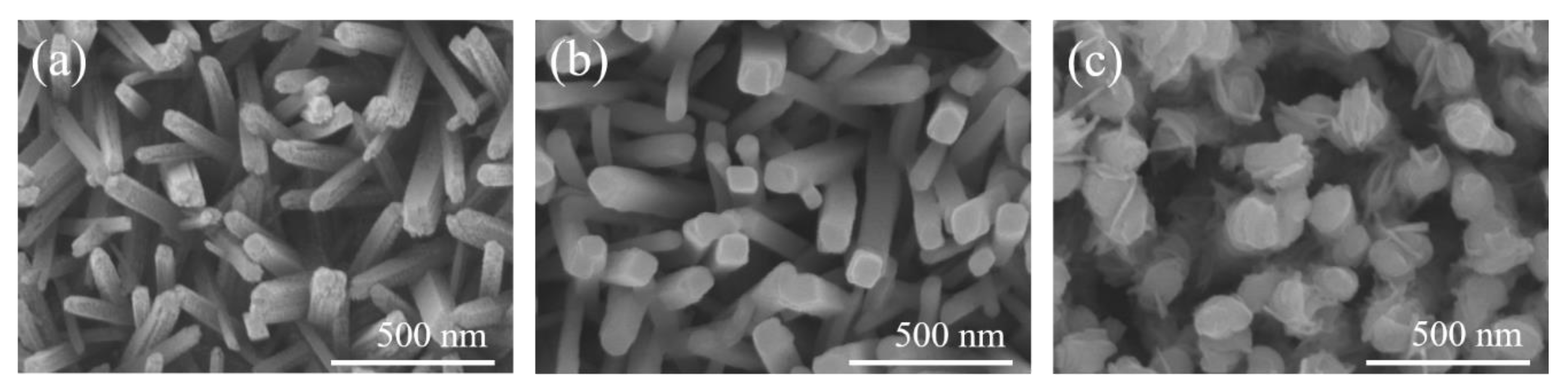
Figure 1a displays the SEM micrograph of hydrothermally derived TiO2 rods on the FTO substrate; these rods had a diameter in the range of approximately 80–110 nm. The TiO2 rods showed tetragonal prismatic morphology. The top surfaces of these rods are uneven, containing numerous up and down edge sites, whereas the sidewalls are smoother. After the sputtering deposition of the s-Bi2O3 thin film onto the TiO2 rods, a change in morphology was observed. The SEM image shown in Figure 1b confirms the coverage of the s-Bi2O3 thin film on the TiO2 rods resulted in top surfaces and sidewalls of the TiO2 rods becoming smooth. Figure 1c shows the SEM image of the TiO2 rods decorated with the a-Bi2O3 thin film. After the decoration of the a-Bi2O3 thin film onto the TiO2 rods, the change in surface morphology was substantial in comparison with the pristine TiO2 rods. The sheet-like Bi2O3 crystals were decorated onto the surfaces of the top region and sidewalls of the TiO2 rods, incurring undulated morphology of the TiO2–Bi2O3 composite rods. It was also shown that the surfaces of the ZnO-Sn2S3 nanorods exhibited undulations and a visible sheet-like crystal texture via sputtering decoration of the Sn2S3 crystals [9]. The sheet-like crystallites on the surfaces of the one-dimensional rods improved specific surface area and is beneficial in enhancing their photoactivity [9]. The SEM images evidently demonstrated that the Bi2O3 crystals were successfully coated on the surfaces of the TiO2 rods through a sputtering assisted method and the s-Bi2O3 and a-Bi2O3 thin films made the TiO2–Bi2O3 composite rods with substantially different rod surface morphologies.
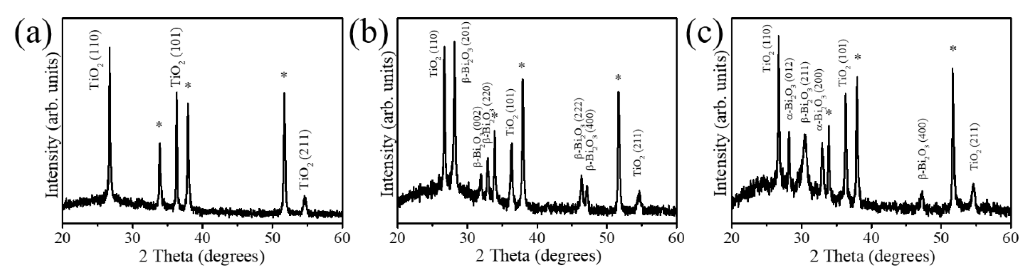
The XRD patterns of the pristine TiO2 rods, TiO2/s–Bi2O3 composite rods, and TiO2/a–Bi2O3 composite rods are shown in Figure 2. In addition to Bragg reflections originated from FTO substrates in Figure 2a (marked with asterisks), distinct Bragg reflections centered at 27.4°, 36.1° and 54.3° can be indexed to (110), (101) and (211) planes of rutile TiO2 phase, respectively (JCPDS No.00-021-1276). The TiO2 rods with a good crystalline phase were formed herein. Figure 2b exhibits the XRD pattern of the TiO2/s–Bi2O3 composite rods. Five differentiable peaks centered at approximately 27.95°, 31.74°, 32.69°, 46.21° and 46.91° in Figure 2b can be assigned to (201), (002), (220), (222) and (400) planes of tetragonal β-Bi2O3 phase, respectively (JCPDS No.01-078-1793). The XRD result demonstrates the sputtering β-Bi2O3 thin film is in a polycrystalline phase. Moreover, the (201) Bragg reflection exhibited a substantially intense feature, revealing (201)-oriented crystals dominated the polycrystalline Bi2O3 thin film decorated onto the surfaces of the rutile TiO2 rods in this study. A similar (201)-orientation dominated polycrystalline β-Bi2O3 has been observed in β-Bi2O3 nanoparticles with an average grain size of 100 nm synthesized by a sol-gel method [18]. Figure 2c exhibits the XRD pattern of the TiO2/a–Bi2O3 composite rods. The major Bragg reflections at 2θ = 28.01° and 33.24°, corresponding to the (012) and (200) planes of the α-Bi2O3 phase were observed (JCPDS No.00-041-1449), revealing formation of a well crystallized monoclinic α-Bi2O3 phase. In addition to Bragg reflections originating from the α-Bi2O3 phase, several Bragg reflections associated with the β-Bi2O3 phase were also observed in Figure 2c. When the TiO2 rods were decorated with a-Bi2O3 thin film, the crystalline composite rods consisted of TiO2 rods and the α/β polymorphic Bi2O3 crystals were formed herein.
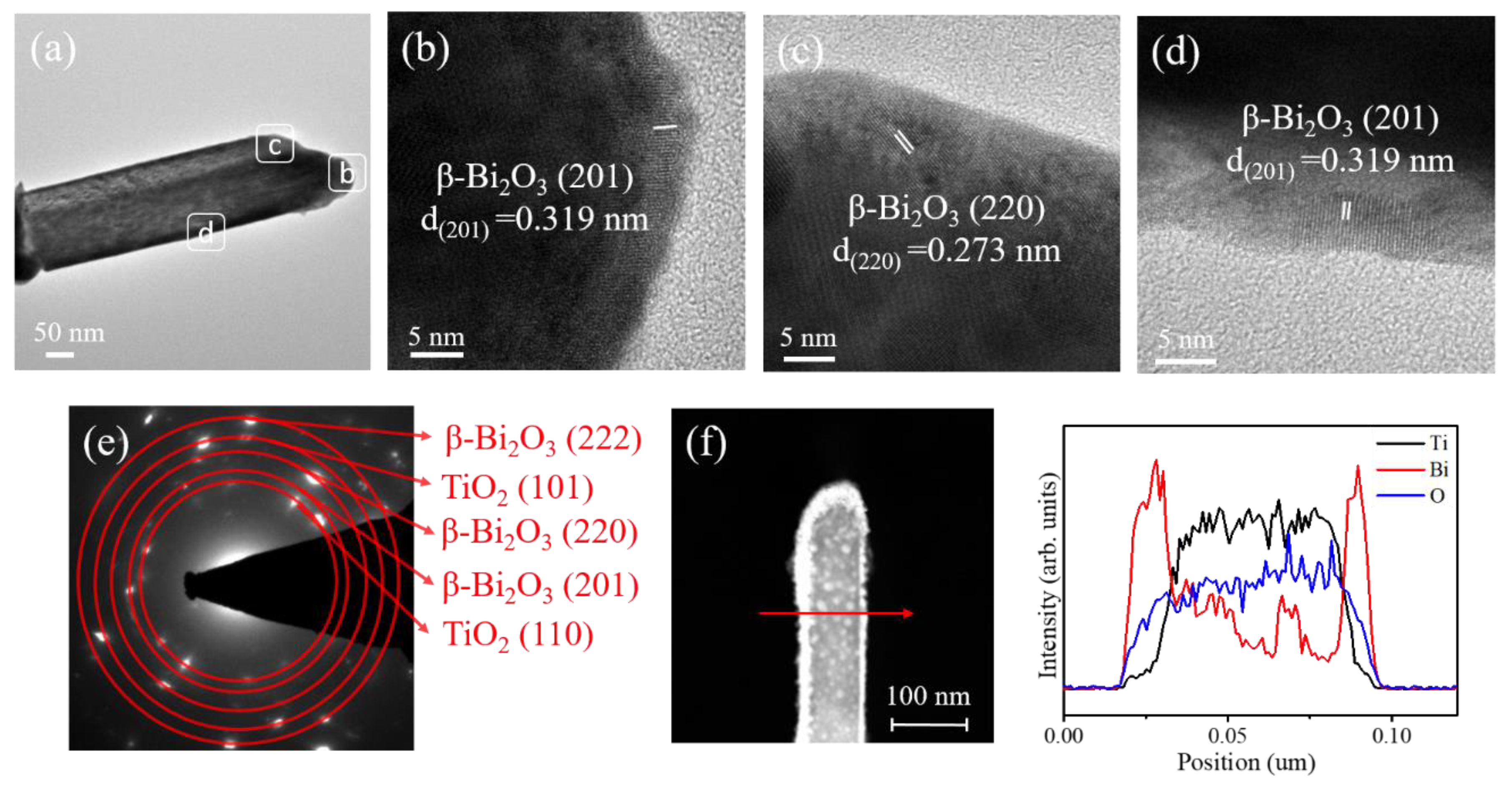
Figure 3a shows a low-magnification transmission electron microscope (TEM) image of a single TiO2/s–Bi2O3 composite rod. A thin and flat β-Bi2O3 layer was homogeneously covered on the surface of the TiO2 rod. The high-resolution (HR) TEM images taken from the various regions of the composite rod are shown in Figs. 3b–d. The lattice fringe spacing of approximately 0.32 nm and 0.27 nm for the outer region of the composite rod corresponded to the interplanar distance of tetragonal β-Bi2O3 (201) and (220) crystallographic planes, respectively, revealing well the crystalline β-Bi2O3 phase formed on the outer region of the composite rod. However, the arrangement of lattice fringes in the inner region of the composite rod is not visibly distinguished because of the overlapped stack of the TiO2 and Bi2O3 oxides. Figure 3e presents the selected area electron diffraction (SAED) pattern obtained from several TiO2/s-Bi2O3 composite rods. It exhibited distinct diffraction spots arranged in circles with various radii. These centric diffraction patterns indicated the co-existence of the crystalline TiO2 and β-Bi2O3 phases, demonstrating the successful growth of the crystalline TiO2–Bi2O3 composite rods via sputtering decoration of β-Bi2O3 crystallites on to the surfaces of the TiO2 rods herein. Figure 3f displays EDS line-scanning profiles across the composite rod. The Ti element was located inside the composite rod, demonstrating the position of the TiO2 rod. The O element was distributed over the cross-sectional region of the whole rod. The Bi element distributed around the TiO2 rod, revealing the successful coverage of the Bi2O3 film on the TiO2. Furthermore, the corresponding HAADF-STEM image in Figure 3f shows the β-Bi2O3 crystals covered on the top region of the TiO2 rod were thicker than that on the lateral region of the composite rod. Moreover, the β-Bi2O3 coverage film on the lateral region of the composite rod had a thickness in the range of approximately 15–28 nm.
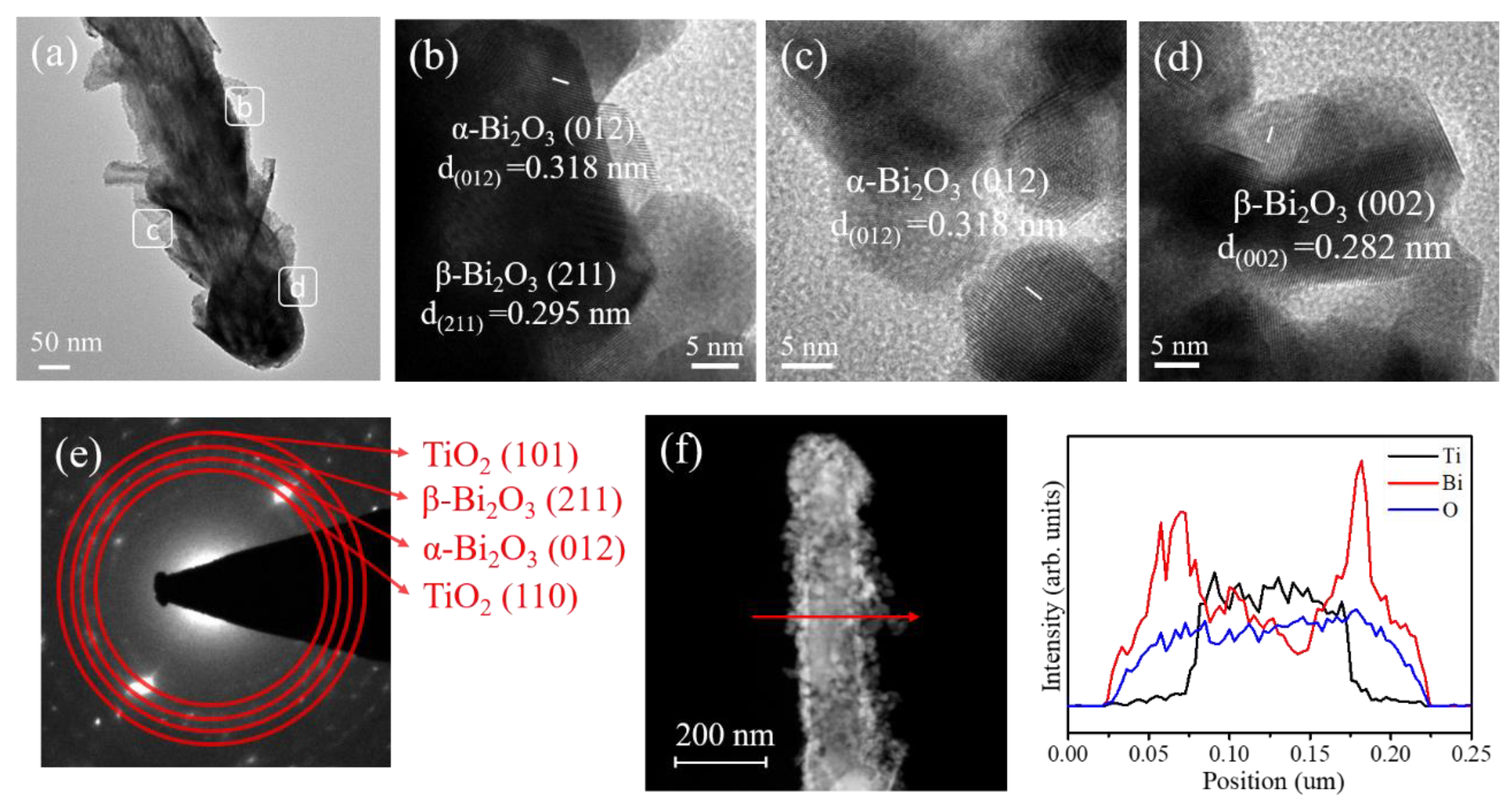
Figure 4a shows a low-magnification TEM image of the TiO2/a–Bi2O3 rod. Unlike the composite rod as displayed in Figure 3a, the Bi2O3 coverage layer exhibited a morphology of randomly oriented sheet-like aggregates consisted of numerous tiny grains. In comparison with the surface morphology of the TiO2/s–Bi2O3 composite rod, the surface crystal size distribution was more non-homogeneous for the TiO2/a–Bi2O3 composite rod. The surface of the TiO2/a–Bi2O3 composite rod was substantially undulated. Figure 4b–d show HRTEM images taken from the outer regions of the composite rod. Notably, many tiny grains were observed in the HR images. These tiny grains aggregated with each other to form the sheet-like crystals as exhibited in Figure 4a. Clear lattice fringes were observed in the constituent tiny grains; the lattice fringe spacing of approximately 0.318 nm is associated with lattice plane distance of the monoclinic α-Bi2O3 (012). Moreover, the lattice fringe spacing of 0.295 nm and 0.282 nm is ascribed to the crystallographic interplanar distance of the (211) and (002) of the β-Bi2O3 phase, respectively. A clear crystalline feature of the Bi2O3 crystals was exhibited in the HRTEM images. Figure 4e shows the SAED pattern of several TiO2/a–Bi2O3 composite rods. The visible spots arranged in centric patterns demonstrate the good crystalline quality of the composite rods. The concentric rings could be attributed to diffraction from the (110) and (101) planes corresponding to the rutile phase of TiO2 and the plane corresponding to the α and β phase Bi2O3. The SAED analysis herein agrees with the XRD pattern, revealing that crystalline TiO2-based composite rods consisted of α/β dual-phase Bi2O3 were formed herein. The cross-sectional EDS line-scanning profiles (Figure 4f) reveal the Bi signals were substantially intense in the outer region and the marked Ti signal was confined to the inner region of the composite rod, indicating that the composite rod consisted of a TiO2 core and a Bi2O3 coverage layer.
Figure 5a,b displays the XPS spectra of the TiO2/s–Bi2O3 and TiO2/a–Bi2O3 composite rods, respectively. The primary peak features in the XPS spectra include the Ti, Bi, and O signals that originated from the TiO2–Bi2O3 composites. Notably, the carbon signal was observed herein because of the carbon surface contamination of the rod samples exposed to ambient air. Moreover, no signals from other elements were detected in the XPS spectra. The experimental results show a composite structure consisted of Ti, Bi, and O elements was formed in this study.
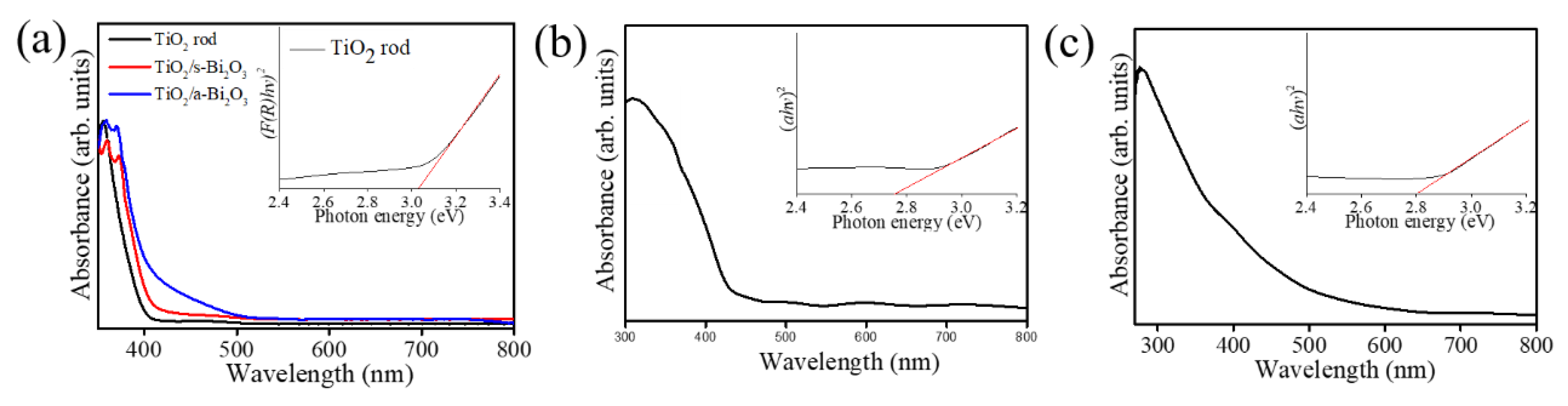
The light absorption properties of the rutile TiO2 rods and various TiO2–Bi2O3 composite rods are shown in Figure 6a. The inset shows the band gap of the TiO2 rods is of approximately 3.03 eV by transferring Kubelka–Munk method [19]. Compared with the pristine TiO2 rods, the construction of the TiO2–Bi2O3 composite rods engendered red-shift of the absorption edge of the TiO2 rods. The TiO2–Bi2O3 composite rods exhibited a broader and stronger light absorption; the main reason for which is the synergistic absorption effect of the Bi2O3 photosensitizer and the formation of TiO2–Bi2O3 heterojunction [20]. The visible light band-gap energy of the Bi2O3 could lead to the broader light absorption region and induce the red shift of the absorption edge of the TiO2–Bi2O3 composite rods [21]. Notably, the absorption edge of the TiO2/a–Bi2O3 composite rods showed a more intense red shift degree than that of the TiO2/s–Bi2O3. The reasons might be associated with the formation of the α/β heterogeneous Bi2O3 and undulated morphology in in the decoration layer of the TiO2 rod surface. For the Bi2O3 films, the transmittance spectra are recorded (Figure 6b,c). The Tauc–Davis–Mott relationship is used to evaluate the bandgap of the thin film [22]. The extrapolated bandgap is approximately 2.75 and 2.80 eV for s-Bi2O3 and a-Bi2O3 thin films, respectively. Notably, the individual bandgap value of the α-phase in the a-Bi2O3 film cannot be separately evaluated in this study. The bandgap analysis herein revealed that the a-Bi2O3 film with an appearance of α-phase contributed to the blue shift of the bandgap energy from 2.75 eV to 2.80 eV in comparison with that of the pure β-phase s-Bi2O3 film (2.75 eV from Figure 6b). This result is supported with the previous reported bandgap of the α-Bi2O3 (2.85 eV) [23]. The formation of a homojunction consisted of the Bi2O3 polymorphs demonstrates a higher light harvesting ability than that of the single constituent counterpart [24]. Moreover, the sheet-like surface crystal feature in a one-dimensional composite has also been shown in several heterogeneous systems that is beneficial for light-harvesting enhancement [9,25].
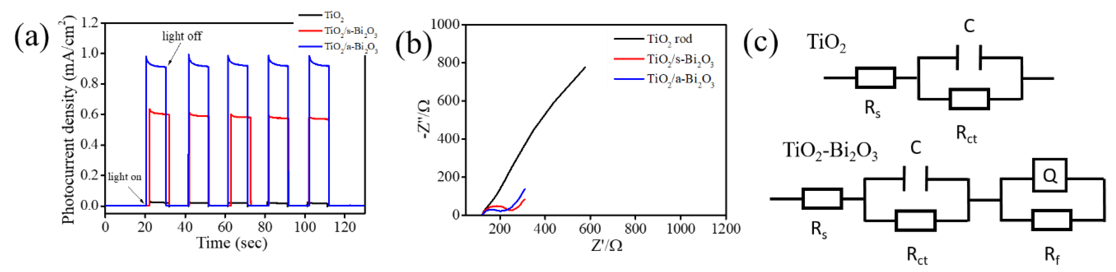
Figure 7a displays photoresponse curves of the TiO2, TiO2/s–Bi2O3, and TiO2/a–Bi2O3 rods at the 1 V under chopped light irradiation. The rod samples showed rapid photoresponse and recovery properties in Figure 7a. The photocurrent density of the pristine TiO2 rod photoelectrode is 0.02 mA cm−2. Furthermore, all TiO2–Bi2O3 composite rods showed markedly enhanced photocurrent density with respect to the pristine TiO2 rods. The photocurrent density of the TiO2/s–Bi2O3 rod photoelectrode is approximately 0.61 mA cm−2 and this photocurrent density is around 30 times higher than that of the pristine TiO2 rod photoelectrode under irradiation. Notably, the TiO2/a–Bi2O3 rod photoelectrode achieved the highest photocurrent density of approximately 0.92 mA cm−2 in this study; this value is approximately 46 times higher than that of the pristine TiO2 rod photoelectrode. A substantial increase in the photocurrent density of the TiO2 rods sputter coated with α/β-Bi2O3 thin films is clearly demonstrated. The marked photocurrent intensity increase upon light irradiation indicates the efficient charge separation capability in the semiconductor oxides [2]. The photoresponse results herein demonstrated that the TiO2/a–Bi2O3 composite rods exhibited the better photoinduced electron-hole separation efficiency as compared with the TiO2/s–Bi2O3 rods. One of the possible reasons is associated with the suitable band alignment between the α- and β- phase Bi2O3 in the Bi2O3 coverage layer of the composite rods and type II band alignments of the TiO2/α- phase Bi2O3 and TiO2/β- phase Bi2O3 in the composite rod system. The multi-junctions in the TiO2/a–Bi2O3 composite rod system explained its superior electron-hole separation efficiency than the TiO2/s–Bi2O3 rod system in which the Bi2O3 coverage layer was in a single β phase. A substantially increased photoactivity has been shown in the multilayered ZnO/ZnS/CdS/CuInS2 core–shell nanowire arrays than that of the ZnO/ZnS nanowire. This is attributable to the formation of type II band aligned multi-junctions in the composite system which markedly enhances photoinduced charge separation efficiency [26]. A similar multi-junction effects has been shown in type II TiO2/CdS–NiOx nanorod system, in which an NiOx layer coverage on the type II TiO2/CdS nanorods substantially increases the photoactivity of the nanorods [27]. Moreover, in comparison with the flat s-Bi2O3 film coverage layer onto the TiO2 rods, the sheet-like crystal feature of the a-Bi2O3 coverage layer in the TiO2–Bi2O3 composite rods markedly increased the light-harvesting ability of the TiO2. The multi-junctions and unique sheet-like surface crystal feature of the TiO2/a–Bi2O3 composite rods explained their superior photoactivity than that of the TiO2/s–Bi2O3 composite rods herein. Figure 7b shows the Nyquist impedance plots of the TiO2, TiO2/s–Bi2O3, and TiO2/a–Bi2O3 rod photoelectrodes under irradiation. It has been shown that a smaller semicircular radius in the high-frequency region represents a lower electron transport resistance and a higher separation efficiency of the photogenerated electrons and holes [28]. In Figure 7b, the radius of semicircular arc of the pristine TiO2 rod photoelectrode is obviously larger than that of all the TiO2–Bi2O3 composite rod photoelectrodes, revealing the composite structure can indeed accelerate the photoinduced electron-hole pair’s separation efficiency. Moreover, the arc radius in the Nyquist curve of the TiO2/a–Bi2O3 photoelectrode is the smallest, implying this composite rod system had the lowest internal charge transfer resistance and can accelerate electron transfer and restrain e-/h+ recombination under light irradiation. A small arc radius and low internal charge transfer resistance for the heterogeneous structure facilitate the interfacial transfer of charges as well as the separation of charge carriers; this has been reported in TiO2/β–Bi2O3 nanotube array composite films via electrodeposition [29]. Figure 7c exhibits the possible equivalent circuits for a quantitative analysis of interfacial charge transfer ability of various rod samples. A similar equivalent circuit for the heterogeneous system herein has been demonstrated in previous reported BiVO4/BiOI and BiOI/BiOIO3 heterogeneous systems [28,30]. As the illustrations show, the intercept of the semicircle in the high frequency region with real axis symbolizes the solution resistance Rs and it depends on the concentration and conductivity of the electrolyte [31]. The C indicates the electric double layer capacitor and Q is the constant-phase element [32]. Rct represents the electron transfer resistance, and it can be estimated through the fitting of arc radii of the Nyquist curves. The Rf represents the rod sample resistance [31]. In general, a small radius of the Nyquist curve indicates a small Rct value for the rod samples. In the current work, the separately evaluated Rct values of the TiO2, TiO2/s–Bi2O3, and TiO2/a–Bi2O3 rods are approximately 7959, 97.97 and 77.46 Ohm. The results from the PEC and EIS experiments demonstrated that the separation and migration processes of photoinduced electron-hole pairs are greatly forwarded in the TiO2/a–Bi2O3 composite rod system herein.
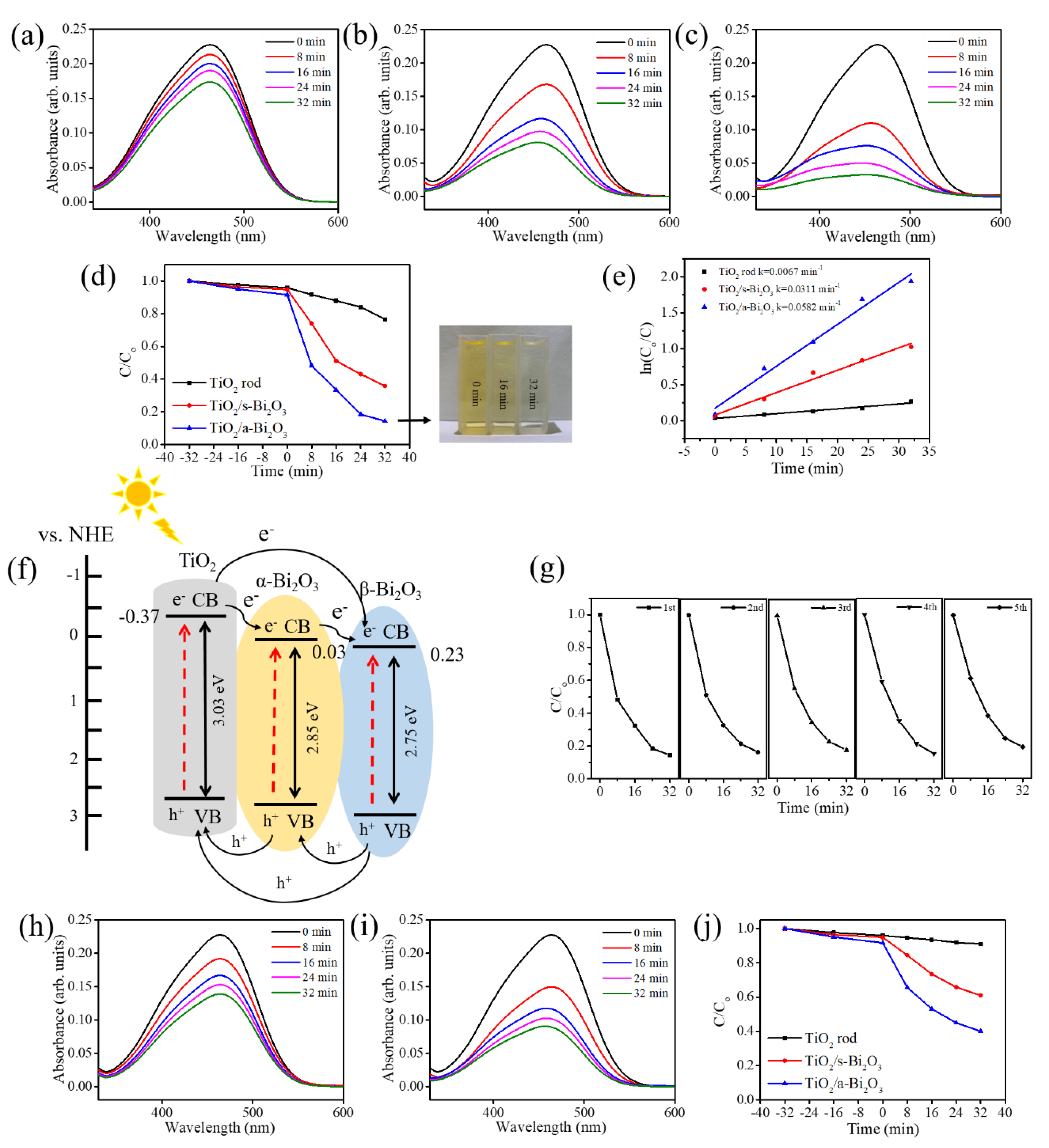
The photoactivities of various rod-like photocatalysts were performed through photocatalytic decomposition experiments involving MO dyes. The pristine TiO2 rods were used in the comparative experiment as a photocatalytic reference to understand the improved photocatalytic activity of the TiO2–Bi2O3 heterogeneous rods. As depicted in Figure 8a–c, the main absorption peaks of the MO solution decreased gradually in the presence of the various rod-like photocatalysts under solar light irradiation with different durations. Comparatively, the drop in absorbance spectrum intensity was more substantial for the MO solution containing TiO2–Bi2O3 composite rods than that for the MO solution containing the pristine TiO2 rods at the given irradiation duration. The photodegradation performance of the MO solution containing various rod samples was evaluated from the concentration ratio of C/Co, in which C is the concentration of the MO solution containing the test samples after a given irradiation time, and Co is the initial concentration of the MO solution without irradiation. The C/Co vs. irradiation duration results for various rod-like photocatalysts are summarized in Figure 8d. Before irradiation, the rod-like photocatalysts were immersed in the MO solution for 32 min to reach adsorption–desorption equilibrium, and the decreased concentration of the MO solution reflected the dye absorptivity onto the surfaces of the rod-like photocatalysts. The C/Co value of the MO solution decreased approximately 6% for the TiO2 and TiO2/s–Bi2O3 photocatalysts and that value was markedly dropped by approximately 9% for the TiO2/a–Bi2O3 photocatalyst at the given dark balance condition. This revealed that the TiO2/a–Bi2O3 photocatalyst exhibited more intense dye absorptivity than other rod-like photocatalysts herein. The C/Co values of the MO solution containing the TiO2, TiO2/s–Bi2O3, and TiO2/a–Bi2O3 rods after 32 min irradiation were approximately 0.76, 0.35 and 0.14, respectively; almost 86% MO dyes are photodegraded in the solution containing the TiO2/a–Bi2O3 photocatalyst. Moreover, the discoloration of the MO solution containing the TiO2/a–Bi2O3 photocatalyst with different irradiation durations is visibly observed in the insets of Figure 8d. The MO solution containing TiO2/a–Bi2O3 photocatalyst became almost translucent after 32 min light irradiation; this is in agreement with the C/Co result. Notably, the construction of TiO2–Bi2O3 heterostructures markedly enhanced the photodegradation efficiency of the TiO2 rods. The kinetic analysis of the MO photodegradation processes containing various rod-like photocatalysts was performed to compare the photodegradation efficiencies of various rod-like photocatalysts. The kinetic linear simulation curves of the photocatalytic MO degradation with different rod-like photocatalysts demonstrated that the degradation reactions follow an apparent first-order kinetic model at low initial concentrations. The kinetic model follows the formula ln (Co/C) = kt herein, where k is the first-order rate constant (min−1) and t is irradiation duration [8]. The k values determined for various rod-like photocatalysts are demonstrated in Figure 8e. The Bi2O3 thin coverage layer shows a significant influence on the photocatalytic degradation performance of the TiO2 rods towards MO dyes. In comparison with the TiO2 rods, the decoration of the β-phase Bi2O3 coverage layer enhanced the k value to 0.0311 min−1; moreover, the decoration of the α/β dual-phase Bi2O3 coverage layer substantially improved the k value to 0.0582 min−1, revealing more efficient enhancement in photoactivity of the TiO2 rod-based photocatalyst using the dual-phase Bi2O3 film. It has been shown that α/β dual-phase Bi2O3 nanofibers demonstrate a higher photoactivity to photodegrade RhB dyes than that of the single-phase constituents [33]. Essentially superior photoactivity in the α/β dual-phase Bi2O3 than that of the β-phase Bi2O3 might explained the superior photocatalytic performance of the TiO2/a–Bi2O3 photocatalyst herein. The possible band alignments between TiO2 rod and a-Bi2O3 film is shown in Figure 8f. The conduction band (CB) and valence band (VB) positions of the TiO2 are at −0.37 eV and 2.66 eV (vs. Normal Hydrogen Electrode, NHE), respectively [34]. The CB and VB positions of the α-Bi2O3 are at 0.03 eV and 2.88 eV (vs. NHE), respectively. Moreover, the CB and VB of β-Bi2O3 are at 0.23 eV and 2.98 eV (vs. NHE), respectively [35]. Furthermore, the type II heterojunctions formed from α-Bi2O3/β-Bi2O3, TiO2/α–Bi2O3, and TiO2/β–Bi2O3 in the TiO2/a–Bi2O3 photocatalyst demonstrates a synergetic effect in the substantially improved photoactivity. The suitable band alignments at the three types of heterogeneous interfaces in the TiO2/a–Bi2O3 photocatalyst improved the photoinduced charge separation efficiency in the composite rods. When the TiO2/a–Bi2O3 photocatalyst was excited by light with photon energy higher or equal to the band gaps of the Bi2O3 and TiO2, photoinduced electrons in the conduction band of TiO2 might flow to that of α-Bi2O3, then reach that of β-Bi2O3. A stepwise transfer of photoinduced electrons in the TiO2/a–Bi2O3 photocatalyst with a stepped heterogeneous energy band structure reduced the recombination number of photoinduced electrons. Simultaneously, photogenerated holes in the valence band of the β-Bi2O3 transfer to that of α-Bi2O3, then to that of TiO2. In the TiO2–Bi2O3 heterogeneous system, the TiO2 acts as a pathway for the transportation of holes. The effective separation of photogenerated carriers in the composite rods herein leads to the enhancement of their photoactivity performance. A similar design of multijunctions with a stepped band alignment configuration formed in the composite structures with three constituent components to improve their photoactivity have been reported in TiO2/CdS–NiOx nanorod and NiO–CdO–ZnO systems [27,36]. The possible reactions involved in the photodegradation process of the MO solution containing the TiO2/a–Bi2O3 photocatalyst are described below [1,2,37]:
α B i 2 O 3 + h v     α B i 2 O 3   ( e ) + α B i 2 O 3   ( h + )
  β B i 2 O 3 + h v     β B i 2 O 3   ( e ) + β B i 2 O 3   ( h + )  
  T i O 2 + h v     T i O 2   ( e ) + T i O 2   ( h + )  
  O H + h +     · O H  
  h + + H 2 O     · O H + H +  
  O 2 + e     · O 2  
  · O 2 + H +     H O 2 ·  
  2 H O 2 ·   O 2 + H 2 O 2  
  H 2 O 2 + · O 2     · O H + O H + O 2  
  · O H + M O     d e g r a d a t i o n   p r o d u c t s  
The hydroxyl radical ⋅OH finally formed from the above possible series reactions can decompose MO dyes directly during the photodegradation process. The photoactivity stability of the TiO2/a–Bi2O3 photocatalyst in photodegrading the MO solution under light irradiation was evaluated using the recycling tests as shown in Figure 8g. After five repeat test cycles, the TiO2/a–Bi2O3 photocatalyst retained consistent photoactivity without apparent deactivation. The retained photoactivity after cycling tests considerably promotes the practical application of this composite structure in eliminating MO dye pollutants. In order to understand the visible light-driven photodegradation effects on the formed heterogeneous systems, control groups including the TiO2/s–Bi2O3 and TiO2/a–Bi2O3 photocatalysts photodegraded towards MO solution at the same irradiation duration but with visible light irradiation were conducted for a comparison. Figure 8h,i show the time-dependent absorbance spectra intensity variation of aqueous MO solution containing TiO2/s–Bi2O3 and TiO2/a–Bi2O3 photocatalysts under visible light irradiation, respectively. It is visibly observed that the intensity of absorbance spectra deceased with visible light irradiation duration. Comparatively, the drop degree of the absorbance spectra intensity is lower than that of the MO solution containing the same photocatalysts under solar light irradiation at the same given irradiation duration (Figure 8b,c). It is supposed that the contribution of photoexcited charges from TiO2 because of its wide bandgap in the UV light region is prohibited to participate in MO dye photodegradation processes herein. The C/Co vs. irradiation duration plots for the MO solution with two different composite photocatalysts are displayed in Figure 8j. The photodegradation degree decreased to approximately 39% and 60% for the MO solution with TiO2/s–Bi2O3 and TiO2/a–Bi2O3 photocatalysts, respectively after 32 min visible light irradiation. Although the MO solution photodegradation from TiO2 was restrained (referred to the result from the C/Co variation with irradiation duration in Figure 8j), the contribution of the Bi2O3 coverage layer under visible light irradiation is clearly visible. Furthermore, the TiO2/a–Bi2O3 photocatalyst exhibited higher visible light photodegradation capability towards MO dyes than that of the TiO2/s–Bi2O3. The effect of the aforementioned α/β heterojunction in the a-Bi2O3 coverage layer film on photoactive performance is also clearly demonstrated in the visible light-driven MO photodegradation testes.

4. Conclusions

In conclusion, the rutile TiO2 rod templates coated with various Bi2O3 phase layers were prepared by in situ sputtering crystal growth and post-annealing procedures in ambient air. The microstructural analysis results demonstrate crystalline TiO2–β-Bi2O3 and TiO2–α/β-Bi2O3 composite rods were formed in this study. In comparison to the flat layered morphology of the β-Bi2O3 coverage film, the α/β-Bi2O3 coverage layer exhibited a sheet-like feature on the TiO2 rod templates. The photoresponse, EIS, and organic dye photodegradation performance results demonstrate that the TiO2 rod templates coated with the α/β-Bi2O3 thin layer substantially improved the photoactivity of the TiO2 rod templates than the TiO2 rod templates coated with β-Bi2O3 thin layer. The unique sheet-like surface crystal feature of the TiO2–α/β-Bi2O3 composite rods increased their light-harvesting ability; moreover, the formation of multi-junctions in the TiO2–α/β-Bi2O3 composite structure efficiently promotes separation of the photoexcited e/h+ pairs and charge transfer ability as well as restrains recombination of the charge carriers. The results herein show that the construction of the TiO2–α/β-Bi2O3 composite rods via the combinational methods consisted of the hydrothermal rod growth, and sputtering and post-annealing assisted thin-film growth is promising for photoactivated devices applications.

Author Contributions

Methodology, K.-J.C.; formal analysis, K.-J.C.; Writing—original draft preparation, Y.-C.L.; supervision, Y.-C.L. All authors have read and agreed to the published version of the manuscript.

Funding

This research was funded by Ministry of Science and Technology of Taiwan. Grant No. MOST 108-2221-E-019-034-MY3.

Conflicts of Interest

The authors declare no conflict of interest.

References

  1. Liang, Y.C.; Chiang, K.J. Design and tuning functionality of rod-like titanium dioxide–nickel oxide composites via a combinational methodology. Nanotechnology 2020, 31, 195709. [Google Scholar] [CrossRef] [PubMed]
  2. Liang, Y.C.; Liu, Y.C. Sputtering control of Ag2O decoration configurations on ZnO nanorods and their surface arrangement effects on photodegradation ability toward methyl orange. Nanotechnology 2019, 30, 495701. [Google Scholar] [CrossRef] [PubMed]
  3. Liang, Y.C.; Liu, Y.C. Microstructures and Photodegradation Performance toward Methylene Orange of Sputtering-Assisted Decoration of ZnFe2O4 Crystallites onto TiO2 Nanorods. Nanomaterials 2019, 9, 205. [Google Scholar] [CrossRef] [PubMed] [Green Version]
  4. Liang, Y.C.; Lo, Y.R.; Wang, C.C.; Xu, N.C. Shell Layer Thickness-Dependent Photocatalytic Activity of Sputtering Synthesized Hexagonally Structured ZnO-ZnS Composite Nanorods. Materials 2018, 11, 87. [Google Scholar] [CrossRef] [Green Version]
  5. Schneider, J.; Matsuoka, M.; Takeuchi, M.; Zhang, J.; Horiuchi, Y.; Anpo, M.; Bahnemann, D.W. Understanding TiO2 Photocatalysis: Mechanisms and Materials. Chem. Rev. 2014, 114, 9919–9986. [Google Scholar] [CrossRef]
  6. Yuan, Y.J.; Ye, Z.J.; Lu, H.W.; Hu, B.; Li, Y.H.; Chen, D.Q.; Zhong, J.S.; Yu, Z.T.; Zou, Z.G. Constructing Anatase TiO2 Nanosheets with Exposed (001) Facets/Layered MoS2 Two-Dimensional Nanojunctions for Enhanced Solar Hydrogen Generation. ACS Catal. 2016, 6, 532–541. [Google Scholar] [CrossRef]
  7. Odhiambo, V.O.; Ongarbayeva, A.; Kéri, O.; Simon, L.; Szilágyi, I.M. Synthesis of TiO2/WO3 Composite Nanofibers by a Water-Based Electrospinning Process and Their Application in Photocatalysis. Nanomaterials 2020, 10, 882. [Google Scholar] [CrossRef]
  8. Liang, Y.C.; Chung, C.C.; Lo, Y.R.; Wang, C.C. Microstructure-Dependent Visible-Light Driven Photoactivity of Sputtering-Assisted Synthesis of Sulfide-Based Visible-Light Sensitizer onto ZnO Nanorods. Materials 2016, 9, 1014. [Google Scholar] [CrossRef] [Green Version]
  9. Liang, Y.C.; Lung, T.W.; Xu, N.C. Photoexcited Properties of Tin Sulfide Nanosheet-Decorated ZnO Nanorod Heterostructures. Nanoscale Res. Lett. 2017, 12, 258. [Google Scholar] [CrossRef] [Green Version]
  10. Li, Y.; Zhao, Y.; Wu, G.; Zhao, J. Facile and Efficient Synthesis of Bismuth Nanowires for Improved Photocatalytic Activity. Inorg. Chem. 2016, 55, 4897–4905. [Google Scholar] [CrossRef]
  11. Raza, W.; Haque, M.M.; Muneer, M.; Harada, T.; Matsumurab, M. Synthesis, characterization and photocatalytic performance of visible light induced bismuth oxide nanoparticle. J. Alloy. Compd. 2015, 648, 641–650. [Google Scholar] [CrossRef]
  12. Sammes, N.M.; Tompsett, G.A.; Näfe, H.; Aldinger, F. Bismuth based oxide electrolytes-structure and ionic conductivity. J. Eur. Ceram. Soc. 1999, 19, 1801–1826. [Google Scholar] [CrossRef]
  13. Qiu, Y.; Yang, M.; Fan, H.; Zuo, Y.; Shao, Y.; Xu, Y.; Yang, X.; Yang, S. Nanowires of α- and β-Bi2O3: Phase-selective synthesis and application in photocatalysis. CrystEngComm 2011, 13, 1843–1850. [Google Scholar] [CrossRef]
  14. Zou, Q.; Li, H.; Yang, Y.P.; Miao, Y.C.; Huo, Y.N. Bi2O3/TiO2 photocatalytic film coated on floated glass balls for efficient removal of organic pollutant. Appl. Surf. Sci. 2019, 467-468, 354–360. [Google Scholar] [CrossRef]
  15. Pang, Y.; Xu, G.; Fan, C.; Lv, J.; Liu, J.; Wu, Y. Photoelectrochemical detection performance and mechanism discussion of Bi2O3 modified TiO2 nanotube arrays. RSC Adv. 2016, 6, 61367–61377. [Google Scholar] [CrossRef]
  16. Zhao, X.; Liu, H.; Qu, J. Photoelectrocatalytic degradation of organic contaminants at Bi2O3/TiO2 nanotube array electrode. Appl. Surf. Sci. 2011, 257, 4621–4624. [Google Scholar] [CrossRef]
  17. Liang, Y.C.; Liu, Y.C. Design of Nanoscaled Surface Morphology of TiO2-Ag2O Composite Nanorods through Sputtering Decoration Process and Their Low-Concentration NO2 Gas-Sensing Behaviors. Nanomaterials 2019, 9, 1150. [Google Scholar] [CrossRef] [Green Version]
  18. Chen, X.; Dai, J.; Shi, G.; Li, L.; Wang, G.; Yang, H. Visible light photocatalytic degradation of dyes by β-Bi2O3/graphene nanocomposites. J. Alloys Compd. 2015, 649, 872–877. [Google Scholar] [CrossRef]
  19. Liang, Y.C.; Lung, T.W. Growth of Hydrothermally Derived CdS-Based Nanostructures with Various Crystal Features and Photoactivated Properties. Nanoscale Res. Lett. 2016, 11, 264. [Google Scholar] [CrossRef] [Green Version]
  20. Ge, M.; Cao, C.; Li, S.; Zhang, S.; Deng, S.; Huang, J.; Li, Q.; Zhang, K.; Al-Deyab, S.S.; Lai, Y. Enhanced photocatalytic performances of n-TiO2 nanotubes by uniform creation of p-n heterojunctions with p-Bi2O3 quantum dots. Nanoscale 2015, 7, 11552–11560. [Google Scholar] [CrossRef]
  21. Tang, X.; Ma, C.; Liu, N.; Liu, C.; Liu, S. Visible light β-Bi2O3/BiOCl heterojunction photocatalyst with highly enhanced photocatalytic activity. Chem. Phys. Lett. 2018, 709, 82–87. [Google Scholar] [CrossRef]
  22. Liang, Y.C.; Liang, Y.C. Physical properties of low temperature sputtering-deposited zirconium-doped indium oxide films at various oxygen partial pressures. Appl. Phys. A 2009, 97, 249–255. [Google Scholar] [CrossRef]
  23. Bera, K.K.; Majumdar, R.; Chakraborty, M.; Bhattacharya, S.K. Phase control synthesis of α, β and α/β Bi2O3 hetero-junction with enhanced and synergistic photocatalytic activity on degradation of toxic dye, Rhodamine-B under natural sunlight. J. Hazard. Mater. 2018, 352, 182–191. [Google Scholar] [CrossRef] [PubMed]
  24. Sun, Y.; Wang, W.; Zhang, L.; Zhang, Z. Design and controllable synthesis of α-/γ-Bi2O3 homojunction with synergetic effect on photocatalytic activity. Chem. Eng. J. 2012, 211–212, 161–167. [Google Scholar] [CrossRef]
  25. Liang, Y.C.; Xu, N.C.; Chiang, K.J. Surface Morphology-Dependent Functionality of Titanium Dioxide–Nickel Oxide Nanocomposite Semiconductors. Nanomaterials 2019, 9, 1651. [Google Scholar] [CrossRef] [PubMed] [Green Version]
  26. Yu, Y.X.; Ouyang, W.X.; Liao, Z.T.; Du, B.B.; Zhang, W.D. Construction of ZnO/ZnS/CdS/CuInS2 Core–Shell Nanowire Arrays via Ion Exchange: P–n Junction Photoanode with Enhanced Photoelectrochemical Activity under Visible Light. ACS Appl. Mater. Interfaces 2014, 6, 8467–8474. [Google Scholar] [CrossRef] [PubMed]
  27. Yoo, I.; Kalanur, S.S.; Seo, H. A nanoscale p-n junction photoelectrode consisting of an NiOx layer on a TiO2/CdS nanorod core-shell structure for highly efficient solar water splitting. Appl. Catal. B. 2019, 250, 200–212. [Google Scholar] [CrossRef]
  28. Huang, H.; Xiao, K.; Liu, K.; Yu, S.; Zhang, Y. In Situ Composition-Transforming Fabrication of BiOI/BiOIO3 Heterostructure: Semiconductor p-n Junction and Dominantly Exposed Reactive Facets. Cryst. Growth Des. 2016, 16, 221–228. [Google Scholar] [CrossRef]
  29. Guan, Z.C.; Wang, H.P.; Wang, X.; Hu, J.; Du, R.G. Fabrication of heterostructured β-Bi2O3-TiO2 nanotube array composite film for photoelectrochemical cathodic protection applications. Corrosion Science 2018, 136, 60–69. [Google Scholar] [CrossRef]
  30. Huang, H.; He, Y.; Du, X.; Chu, P.K.; Zhang, Y. A General and Facile Approach to Heterostructured Core/Shell BiVO4/BiOI p-n Junction: Room-Temperature in Situ Assembly and Highly Boosted Visible-Light Photocatalysis. ACS Sustainable Chem. Eng. 2015, 3, 3262–3273. [Google Scholar] [CrossRef]
  31. Ahila, M.; Subramanian, E.; Pathinettam Padiyan, D. Influence of annealing on phase transformation and specific capacitance enhancement in Bi2O3. J. Electroanal. Chem. 2017, 805, 146–158. [Google Scholar]
  32. Atta, N.F.; Ibrahima, A.H.; Galal, A. Nickel oxide nanoparticles/ionic liquid crystal modified carbon composite electrode for determination of neurotransmitters and paracetamol. New J. Chem. 2016, 40, 662–673. [Google Scholar] [CrossRef]
  33. Lim, G.D.; Yoo, J.H.; Ji, M.; Lee, Y.I. Visible light driven photocatalytic degradation enhanced by α/β dual phase heterojunctions on electrospun Bi2O3 nanofibers. J. Alloys Compd. 2019, 806, 1060–1067. [Google Scholar] [CrossRef]
  34. Paola, A.D.; Bellardita, M.; Palmisano, L. Brookite the Least Known TiO2 Photocatalyst. Catalysts 2013, 3, 36–73. [Google Scholar] [CrossRef] [Green Version]
  35. Lebedev, A.; Anariba, F.; Li, X.; Leng, D.S.H.; Wu, P. Rational design of visible-light-driven Pd-loaded α/β-Bi2O3 nanorods with exceptional cationic and anionic dye degradation properties. Solar Energy 2019, 190, 531–542. [Google Scholar] [CrossRef]
  36. Munawar, T.; Iqbal, F.; Yasmeen, S.; Mahmood, K.; Hussain, A. Multi metal oxide NiO-CdO-ZnO nanocomposite–synthesis, structural, optical, electrical properties and enhanced sunlight driven photocatalytic activity. Ceram. Int. 2020, 46, 2421–2437. [Google Scholar] [CrossRef]
  37. Liu, X.; Deng, H.; Yao, W.; Jiang, Q.; Shen, J. Preparation and photocatalytic activity of Y-doped Bi2O3. J. Alloys Compd. 2015, 651, 135–142. [Google Scholar] [CrossRef]
Figure 1. Scanning electron microscope (SEM) images: (a) TiO2 rods. (b) TiO2/s–Bi2O3 rods, (c) TiO2/a–Bi2O3 rods.
Nanomaterials 10 01005 g001
Figure 2. X-ray diffraction (XRD) patterns: (a) rutile TiO2 rods. (b) TiO2/s–Bi2O3 rods, (c) TiO2/a–Bi2O3 rods. The asterisks denoted Bragg reflections from the F-doped SnO2 (FTO) substrate.
Nanomaterials 10 01005 g002
Figure 3. Transmission electron microscopy (TEM) analysis of the TiO2/s–Bi2O3 rods: (a) Low-magnification TEM image. (bd) High-resolution (HR)TEM images taken from various regions of the composite rod. (e) Selected area electron diffraction (SAED) pattern of several TiO2/s–Bi2O3 rods. (f) Energy-dispersive X-ray spectroscopy (EDS) line scanning profiles across the composite rod.
Nanomaterials 10 01005 g003
Figure 4. TEM analysis of the TiO2/a–Bi2O3 rods: (a) Low-magnification TEM image. (bd) HRTEM images taken from various regions of the composite rod. (e) SAED pattern of several TiO2/a–Bi2O3 rods. (f) EDS line scanning profiles across the composite rod.
Nanomaterials 10 01005 g004
Figure 5. X-ray photoelectron spectroscopy (XPS) analysis: (a) TiO2/s–Bi2O3 and (b) TiO2/a–Bi2O3 rods.
Nanomaterials 10 01005 g005
Figure 6. (a) Absorbance spectra of various rod samples. (b) Absorbance spectrum of the s-Bi2O3 thin film. (c) Absorbance spectrum of the a-Bi2O3 thin film. The insets show the bandgap of the TiO2 rods, s-Bi2O3 film, and a-Bi2O3 film.
Nanomaterials 10 01005 g006
Figure 7. (a) Transient photocurrent density versus time curves of various rod samples under chopped irradiation at 1 V. (b) Nyquist plots of various rod samples under light irradiation. (c) The possible equivalent circuit used for Rct evaluation of various rod samples.
Nanomaterials 10 01005 g007
Figure 8. The irradiation duration dependent absorption spectra of the methylene orange (MO) solution containing various rod samples: (a) TiO2 rods, (b) TiO2/s–Bi2O3 rods, (c) TiO2/a–Bi2O3 rods. (d) C/Co versus irradiation duration plot. The insets show the discoloration of the MO solution containing the TiO2/a–Bi2O3 rods under various irradiation durations. (e) ln (Co/C) versus irradiation duration plot. (f) The possible band alignments of the TiO2/a–Bi2O3 composite structure. (g) Recycling photodegradation tests of the MO solution containing TiO2/a–Bi2O3 composite rods under irradiation. The visible light irradiation time-dependent absorbance spectra intensity variation of the MO solution containing (h) TiO2/s–Bi2O3 and (i)TiO2/a–Bi2O3 photocatalysts. (j) C/Co vs. visible light irradiation duration plots of the MO solution containing various composite rods.
Nanomaterials 10 01005 g008

