Automobile Exhaust Removal Performance of Pervious Concrete with Nano TiO2 under Photocatalysis


Abstract
:1. Introduction
2. Photocatalytic Degradation Mechanism
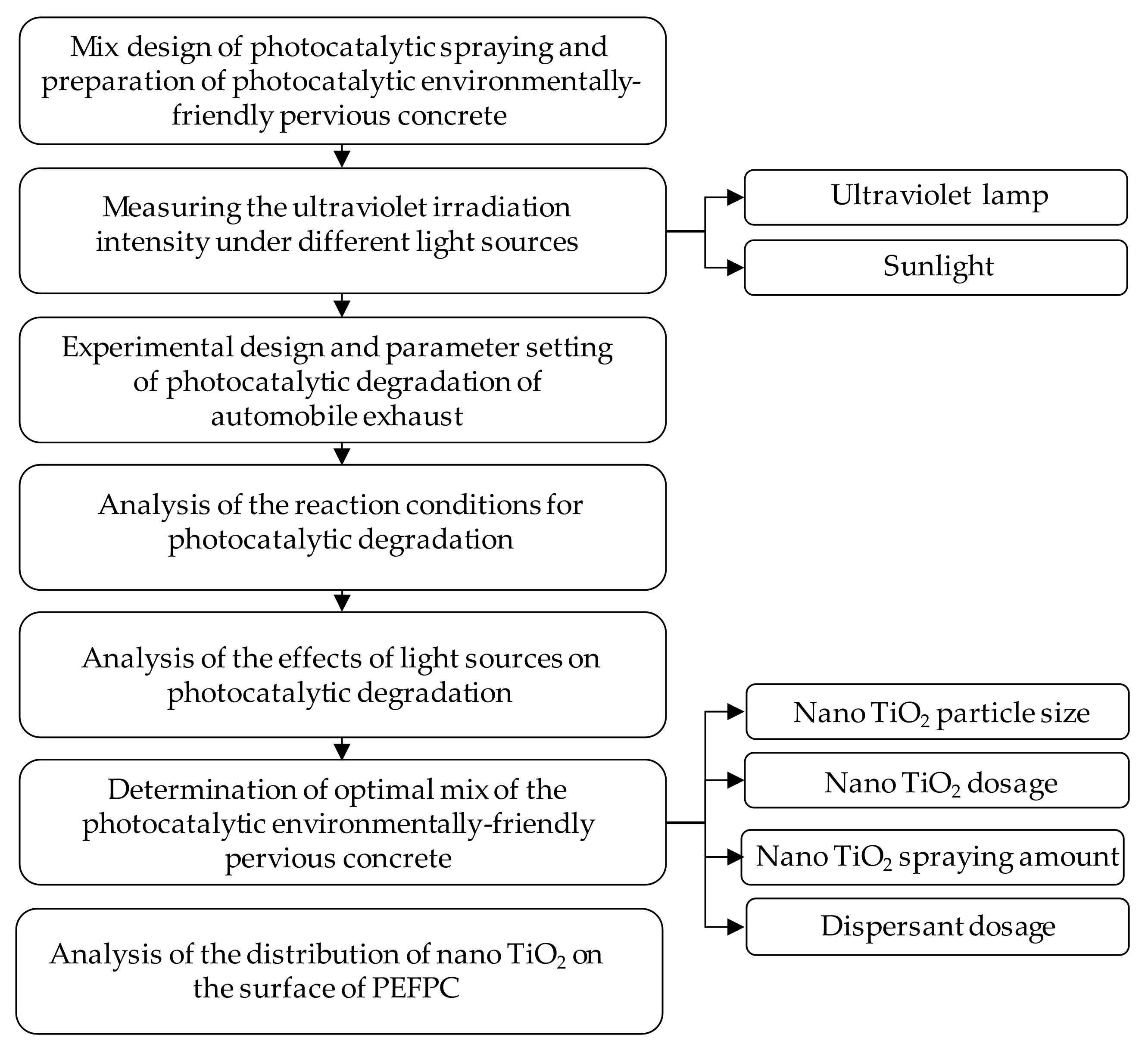
3. Materials and Methods
3.1. Materials
3.2. Preparation of the Photocatalytic Environmentally Friendly Pervious Concrete
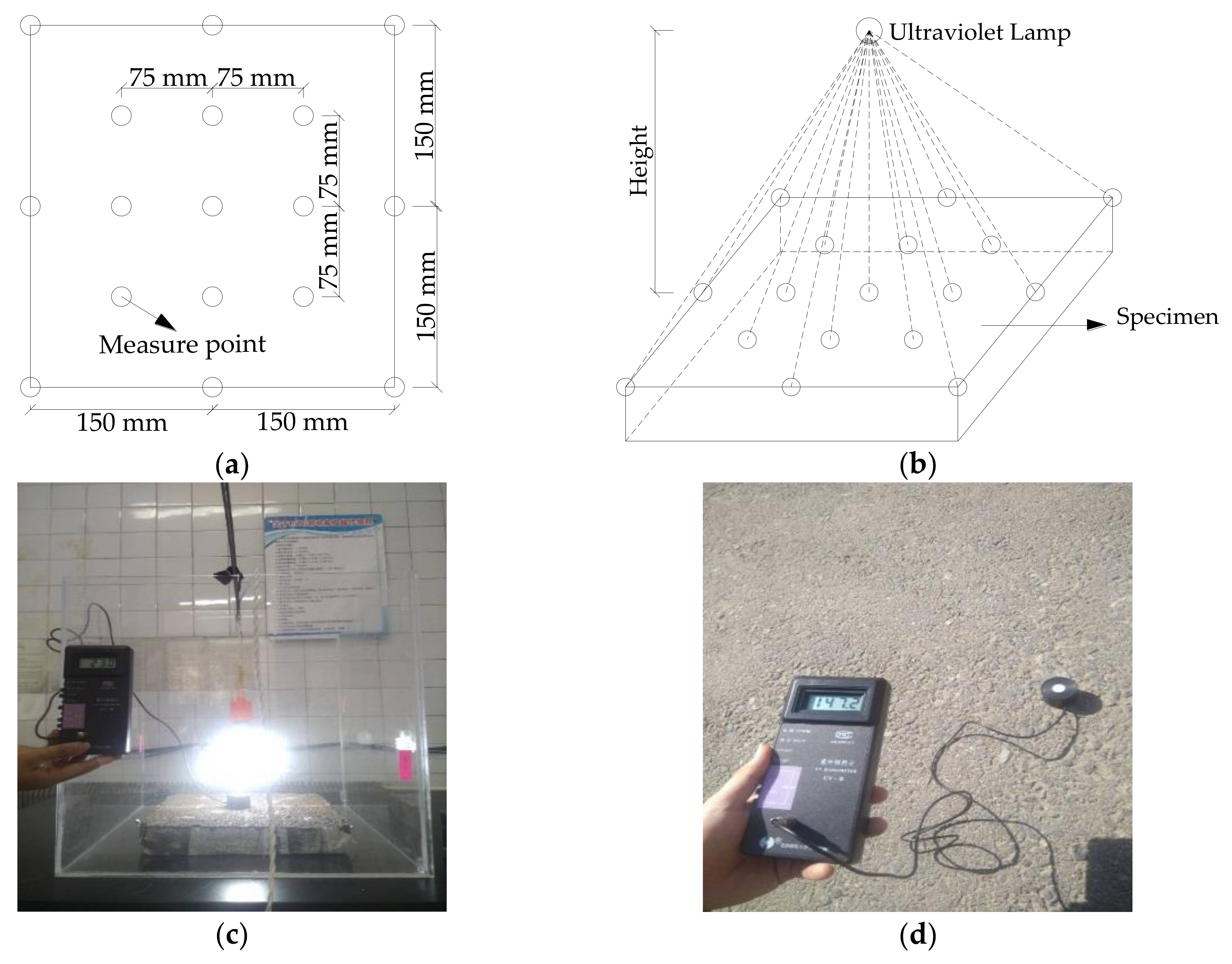
3.3. Determination of Light Intensity
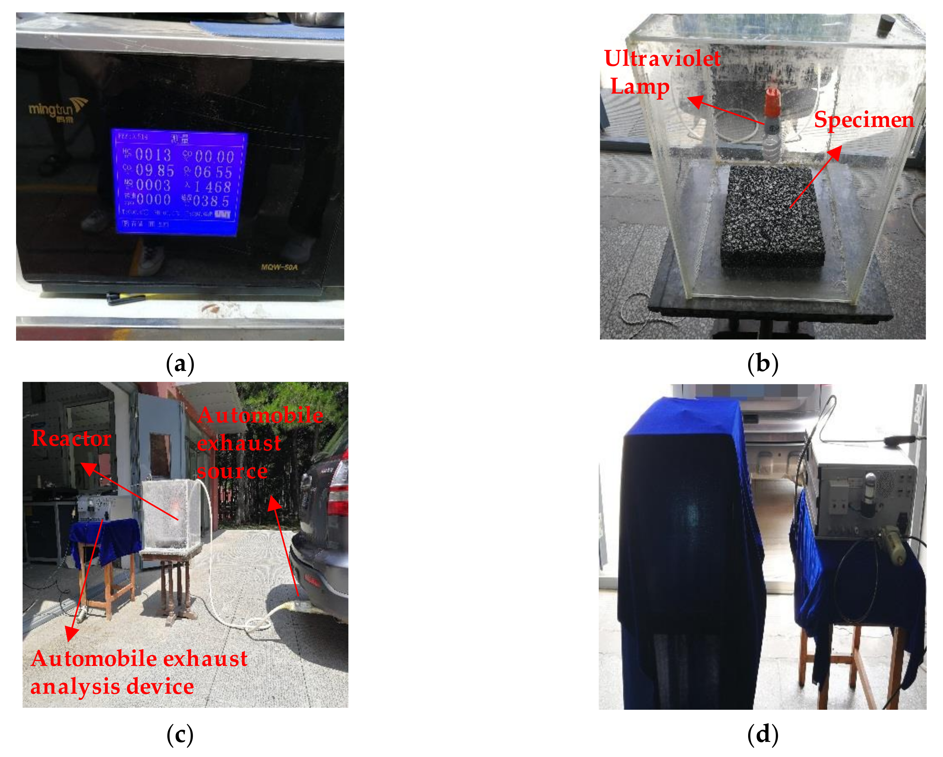
3.4. Photocatalytic Degradation Experiment
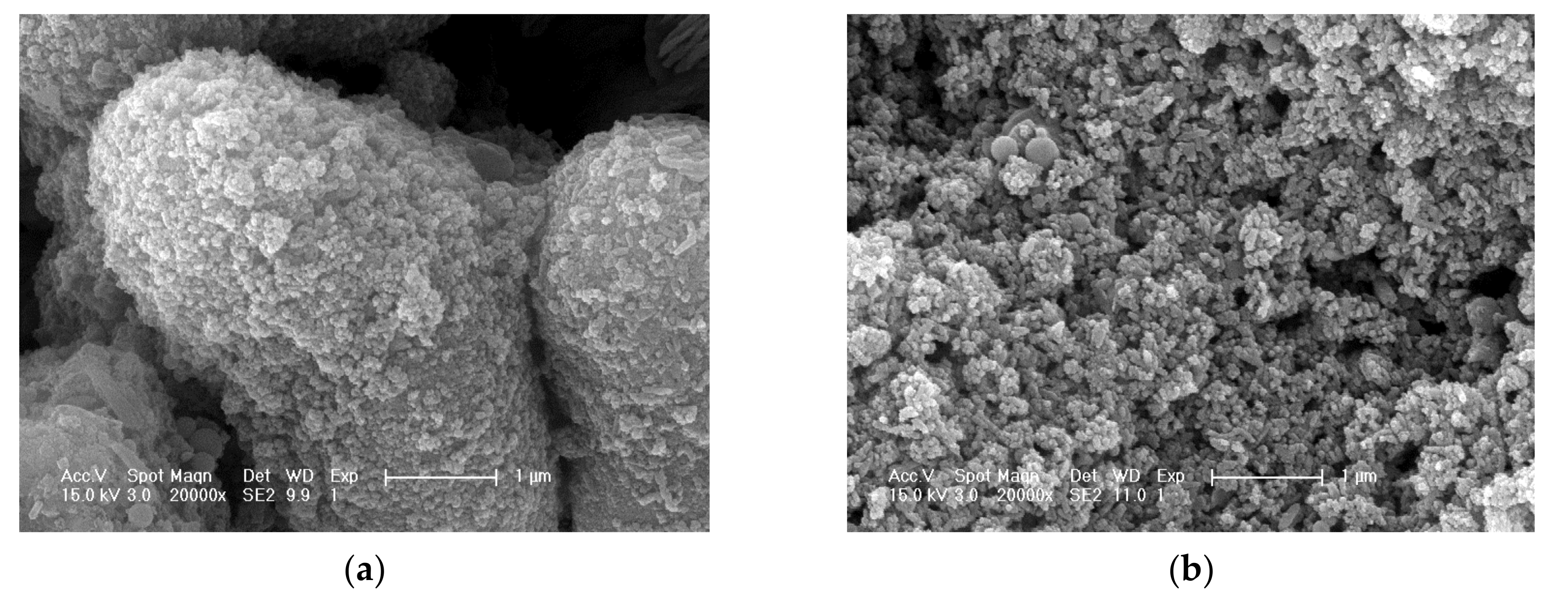
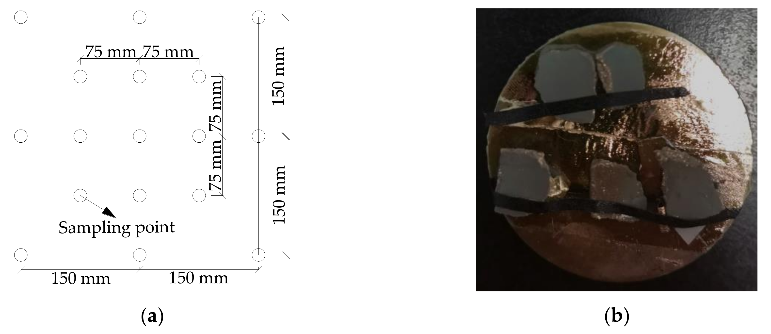
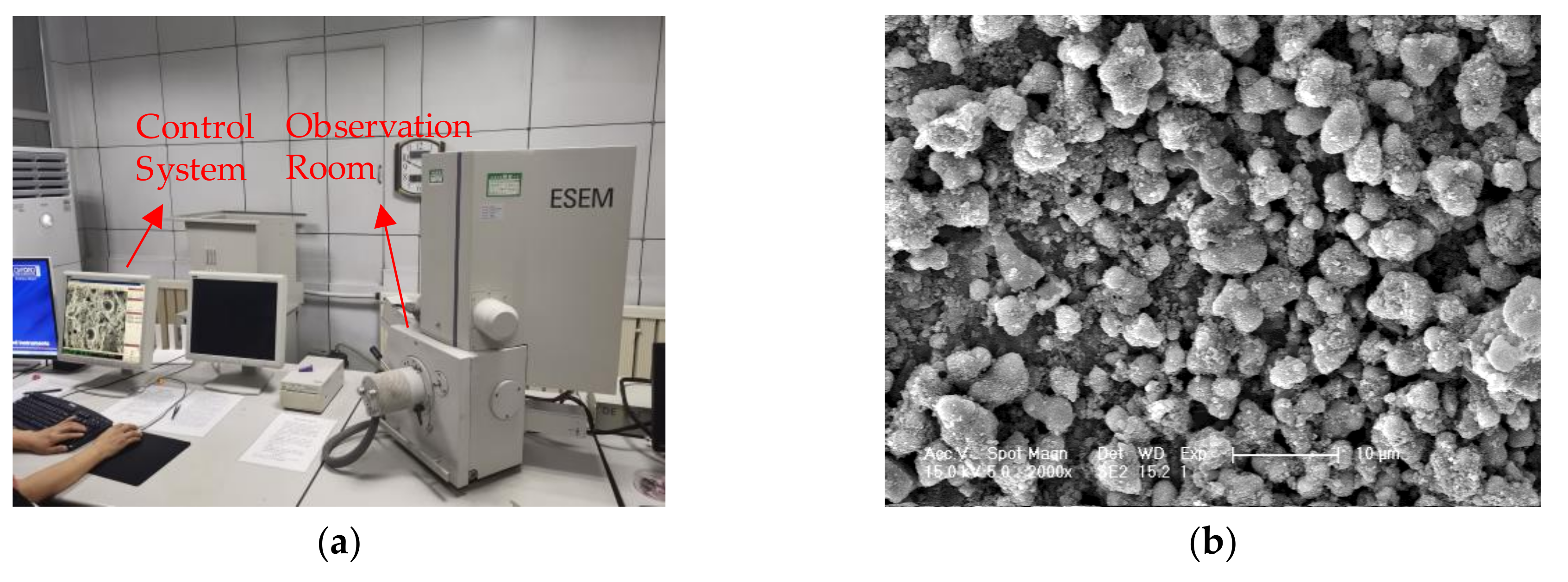
3.5. ESEM
4. Results
4.1. The Reaction Conditions for Photocatalytic Degradation
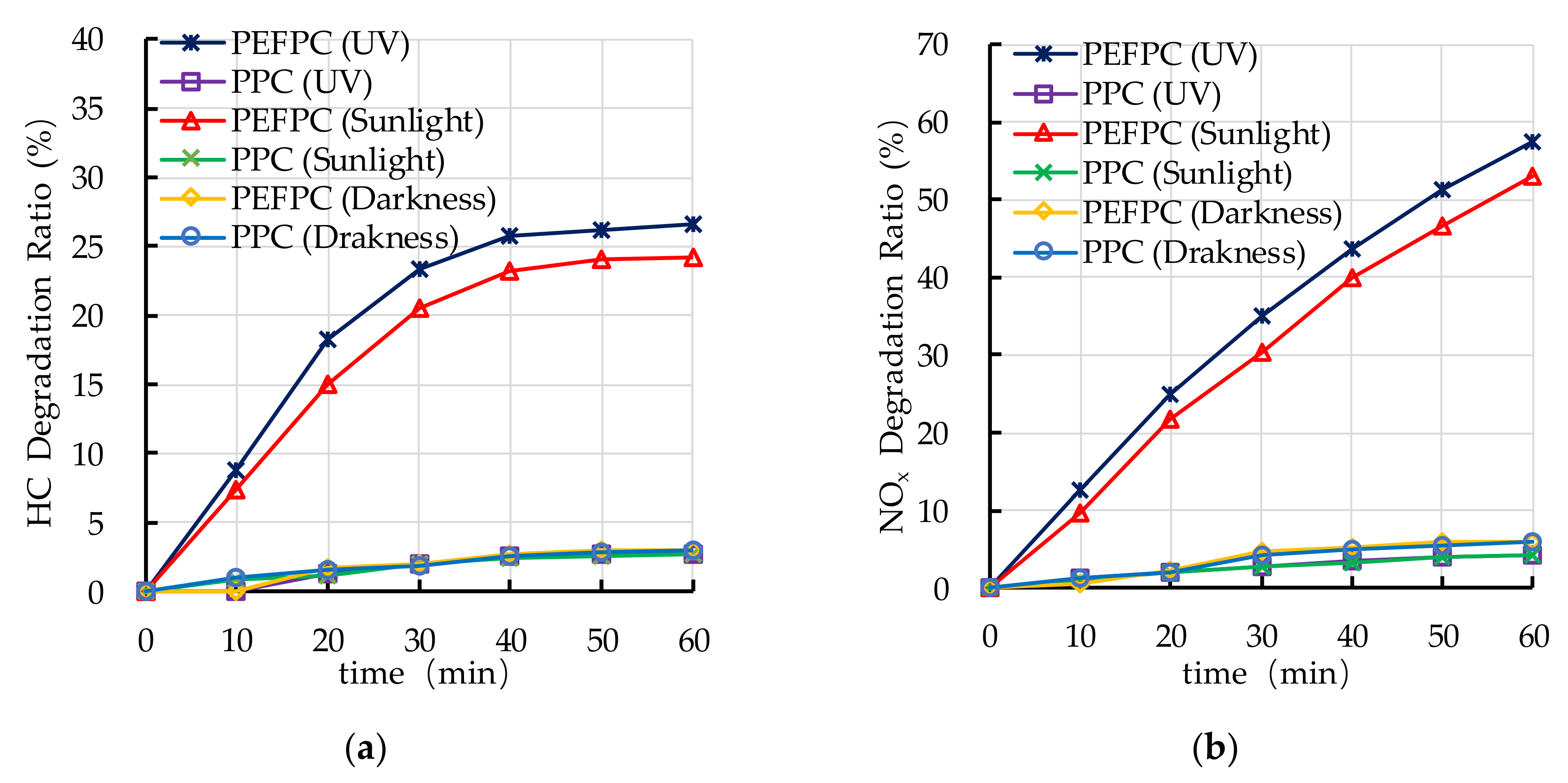
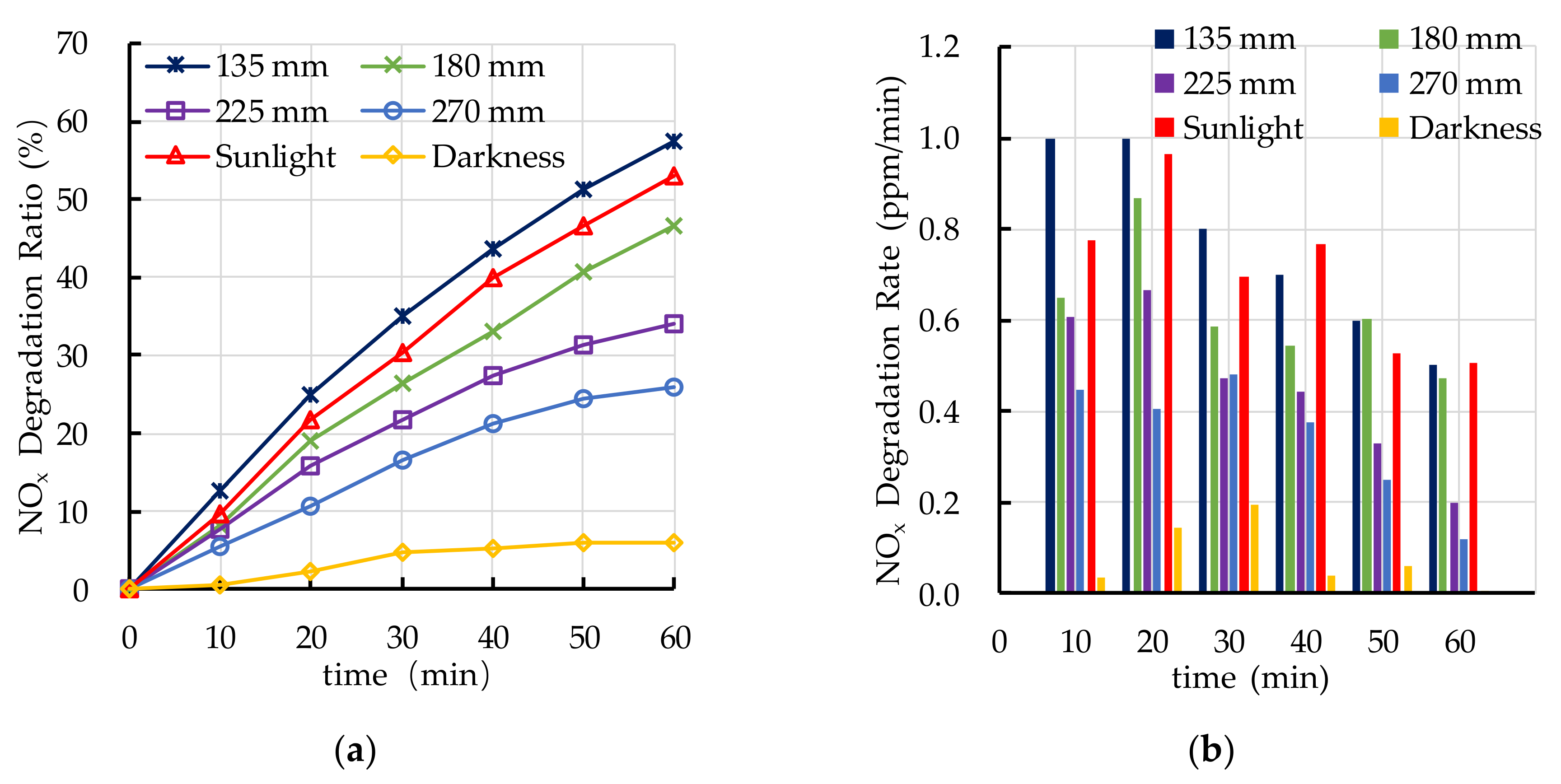
4.2. Effect of Light Source on Photocatalytic Degradation
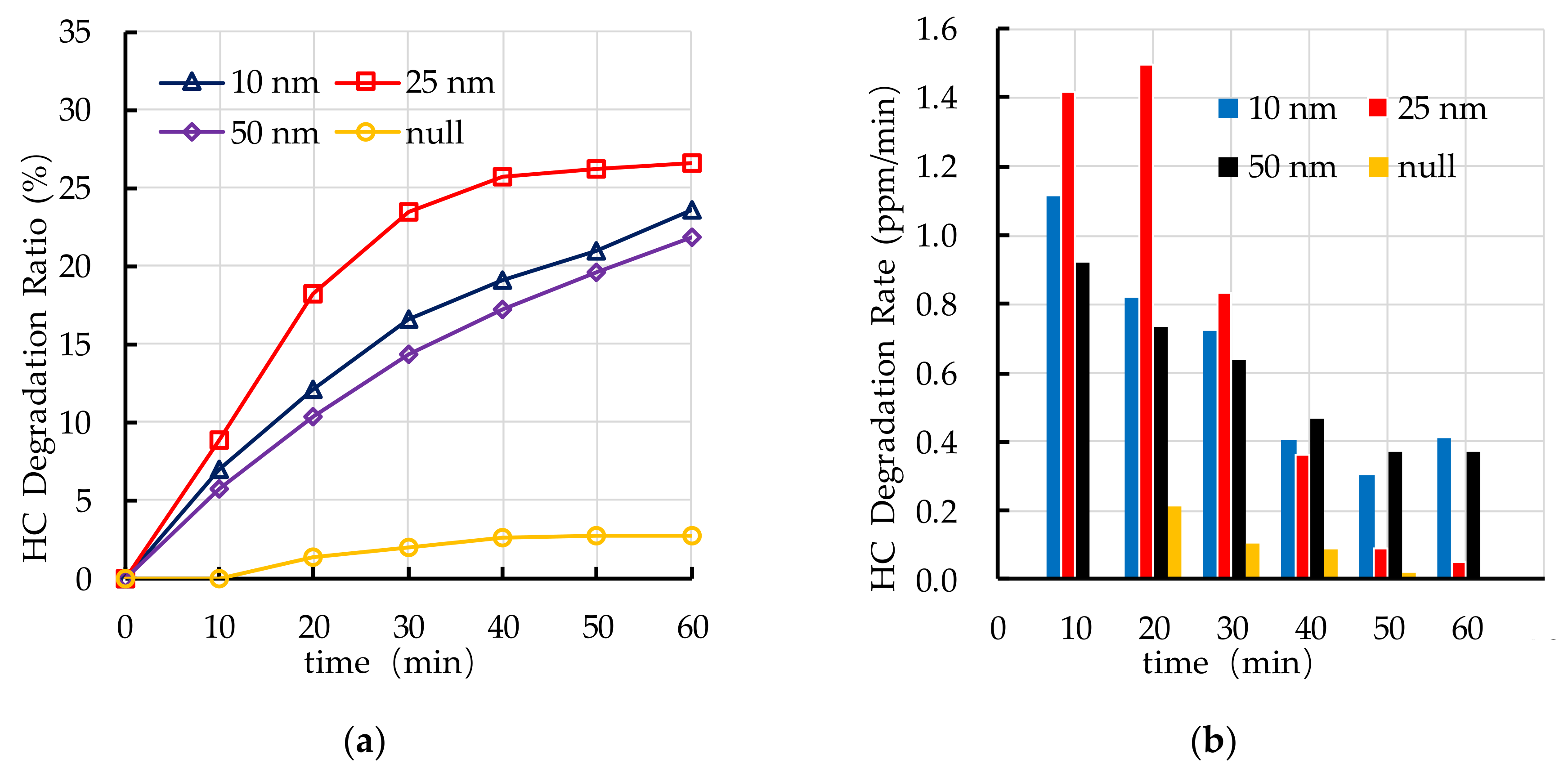
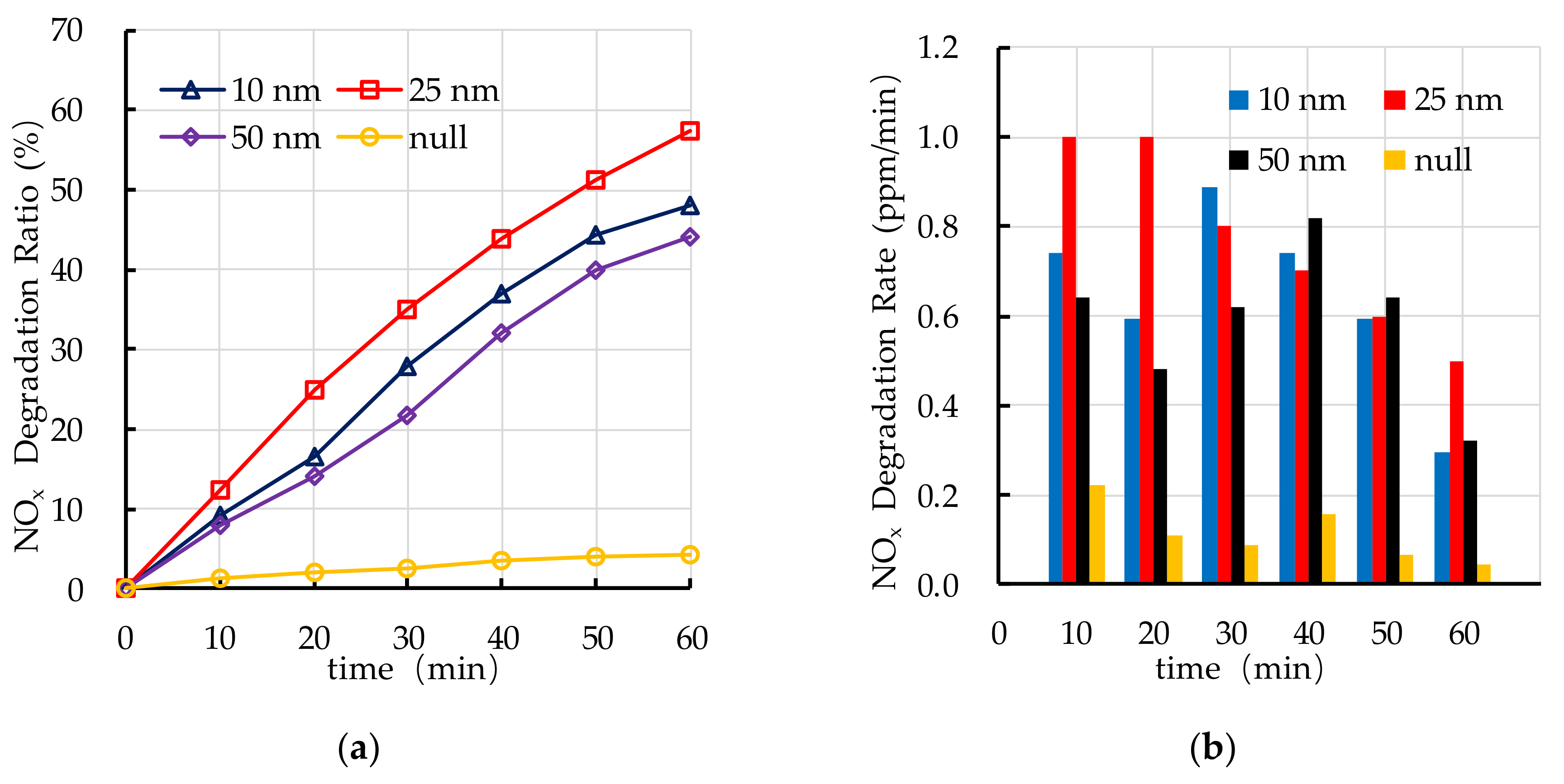
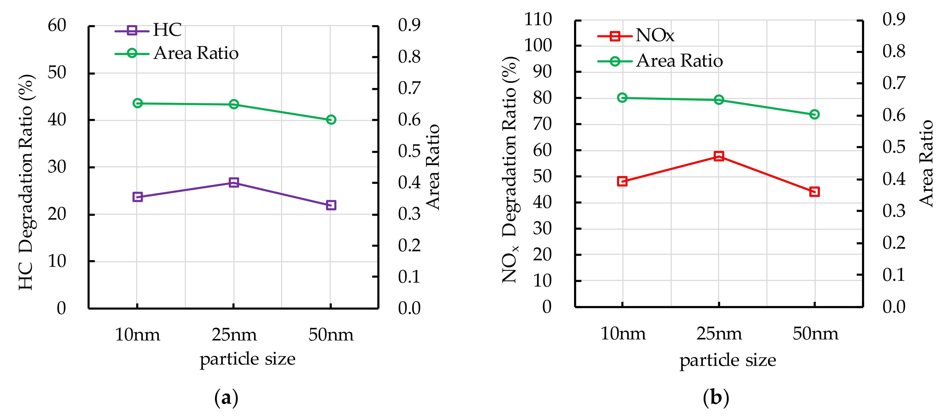
4.3. Effect of TiO2 Particle Size on Photocatalytic Degradation
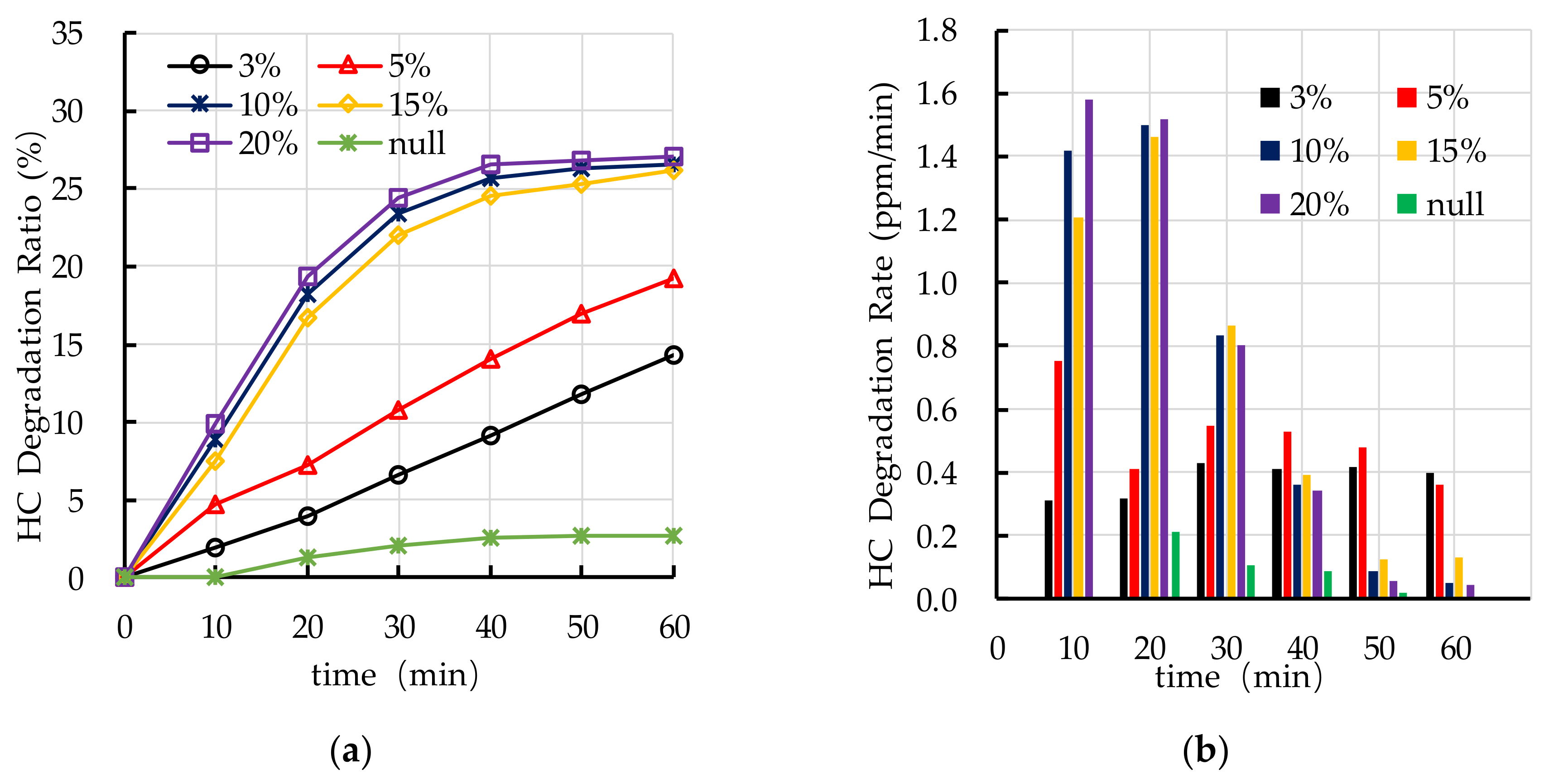
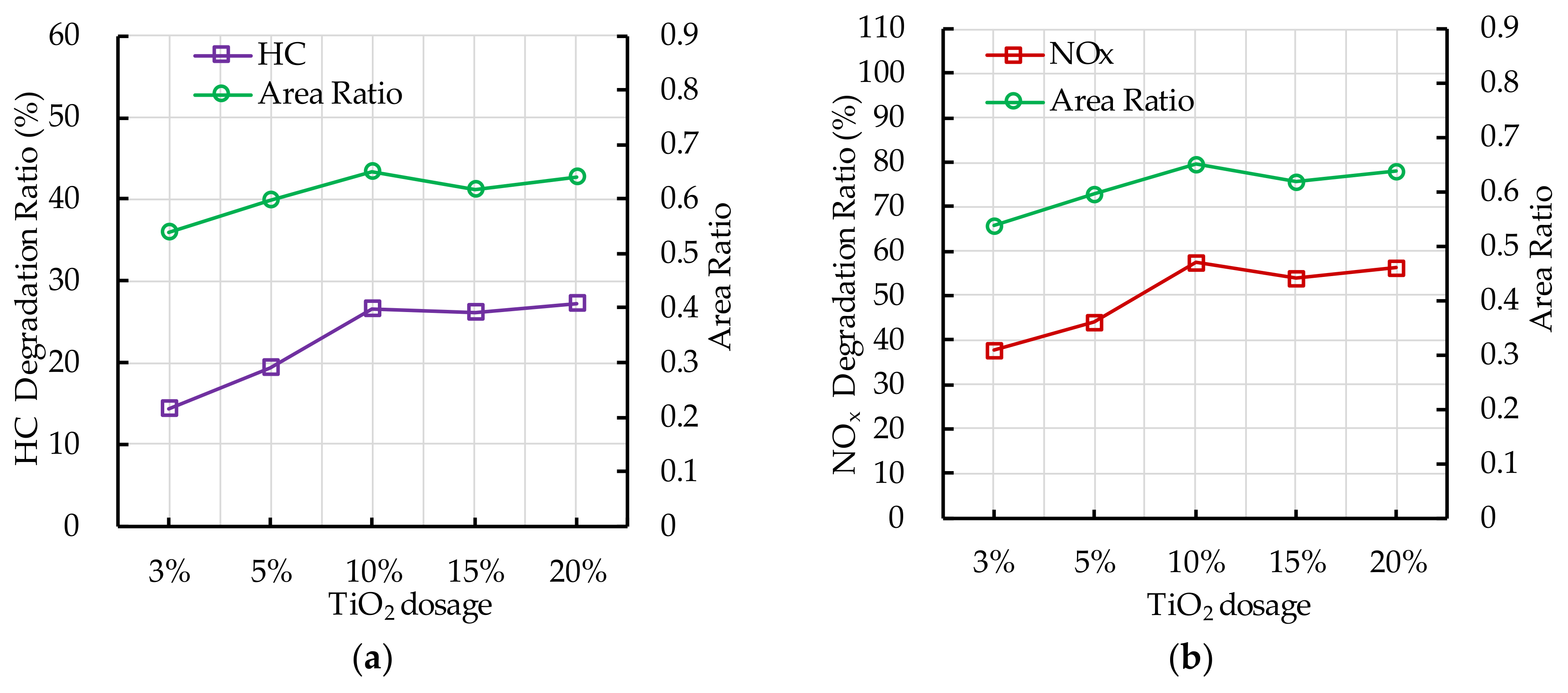
4.4. Effect of TiO2 Dosage on Photocatalytic Degradation
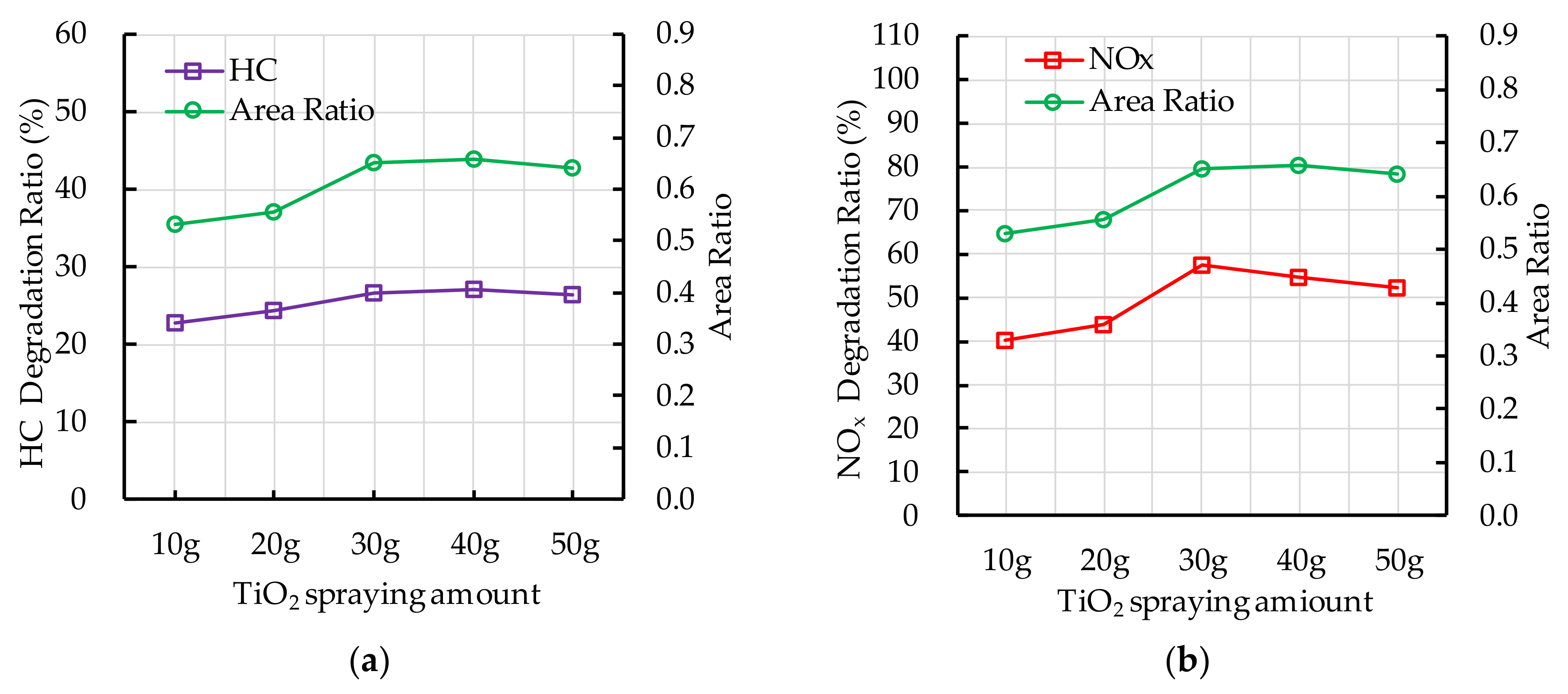
4.5. Effect of TiO2 Spraying Amount on Photocatalytic Degradation
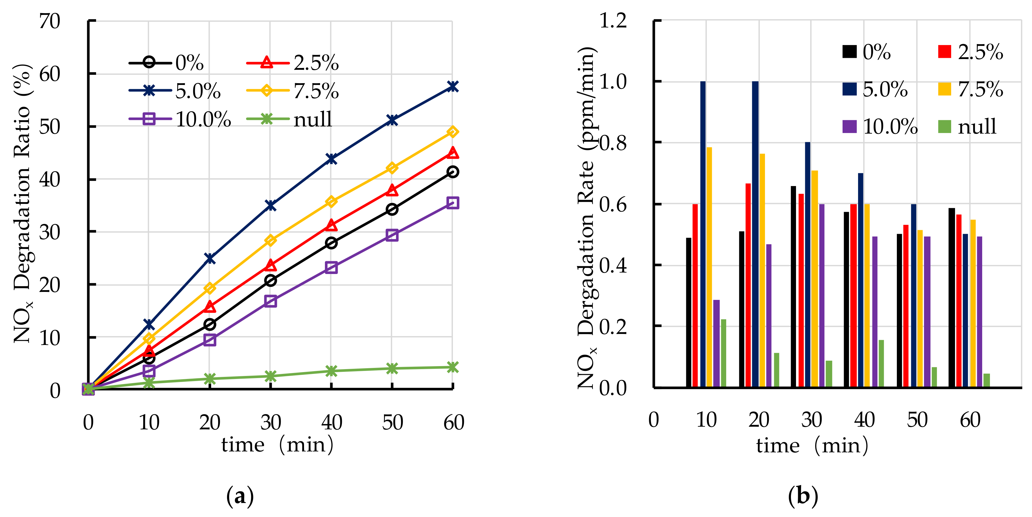
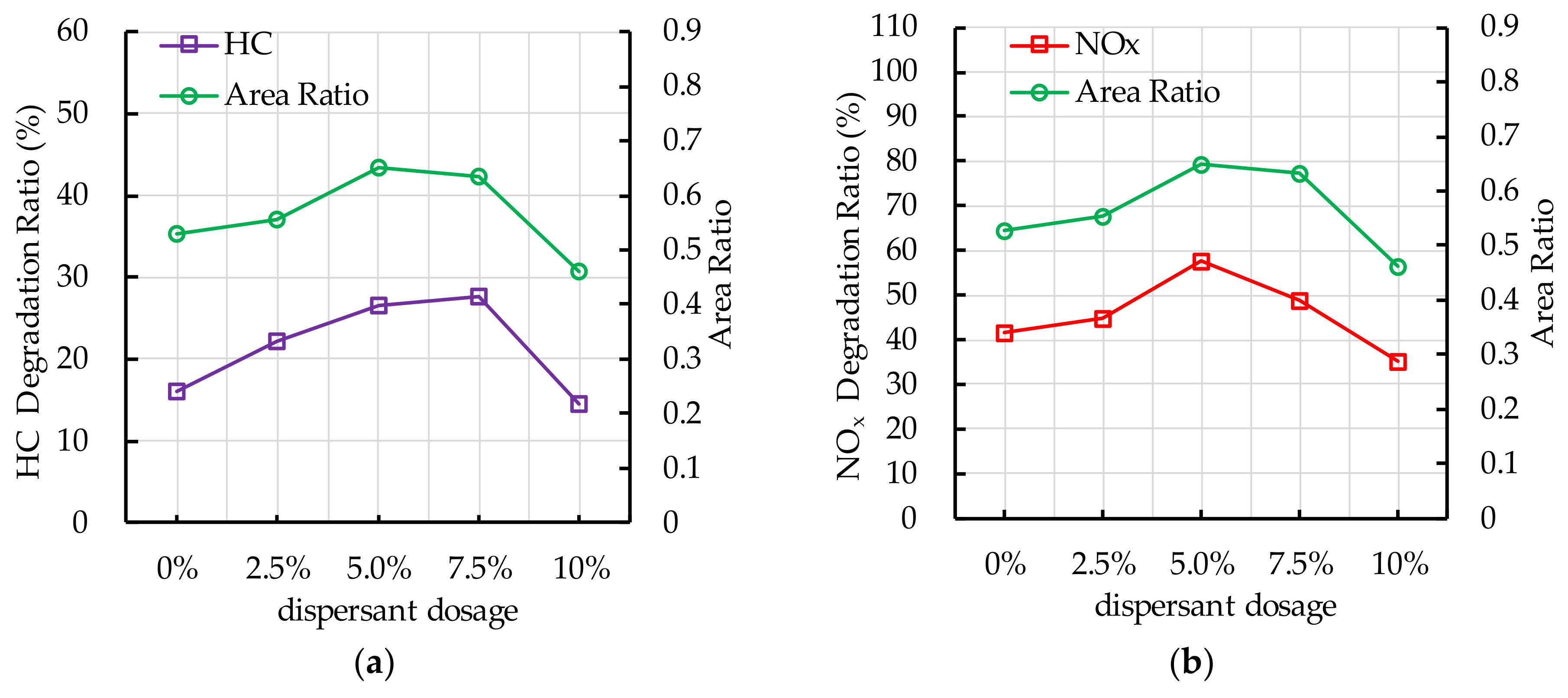
4.6. Effect of Dispersant Dosage on Photocatalytic Degradation
5. Discussion
5.1. TiO2 Particle Size
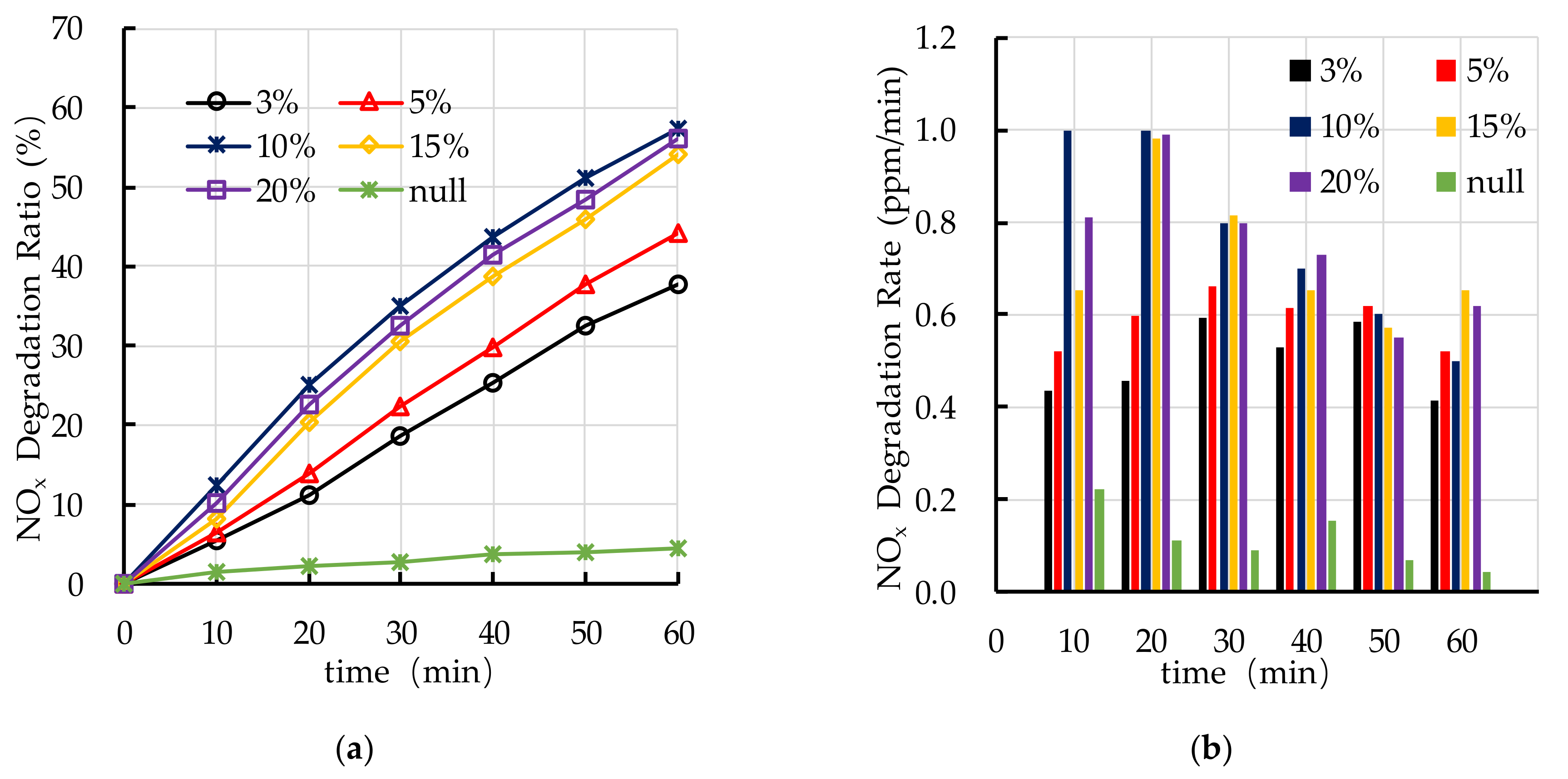
5.2. TiO2 Dosage
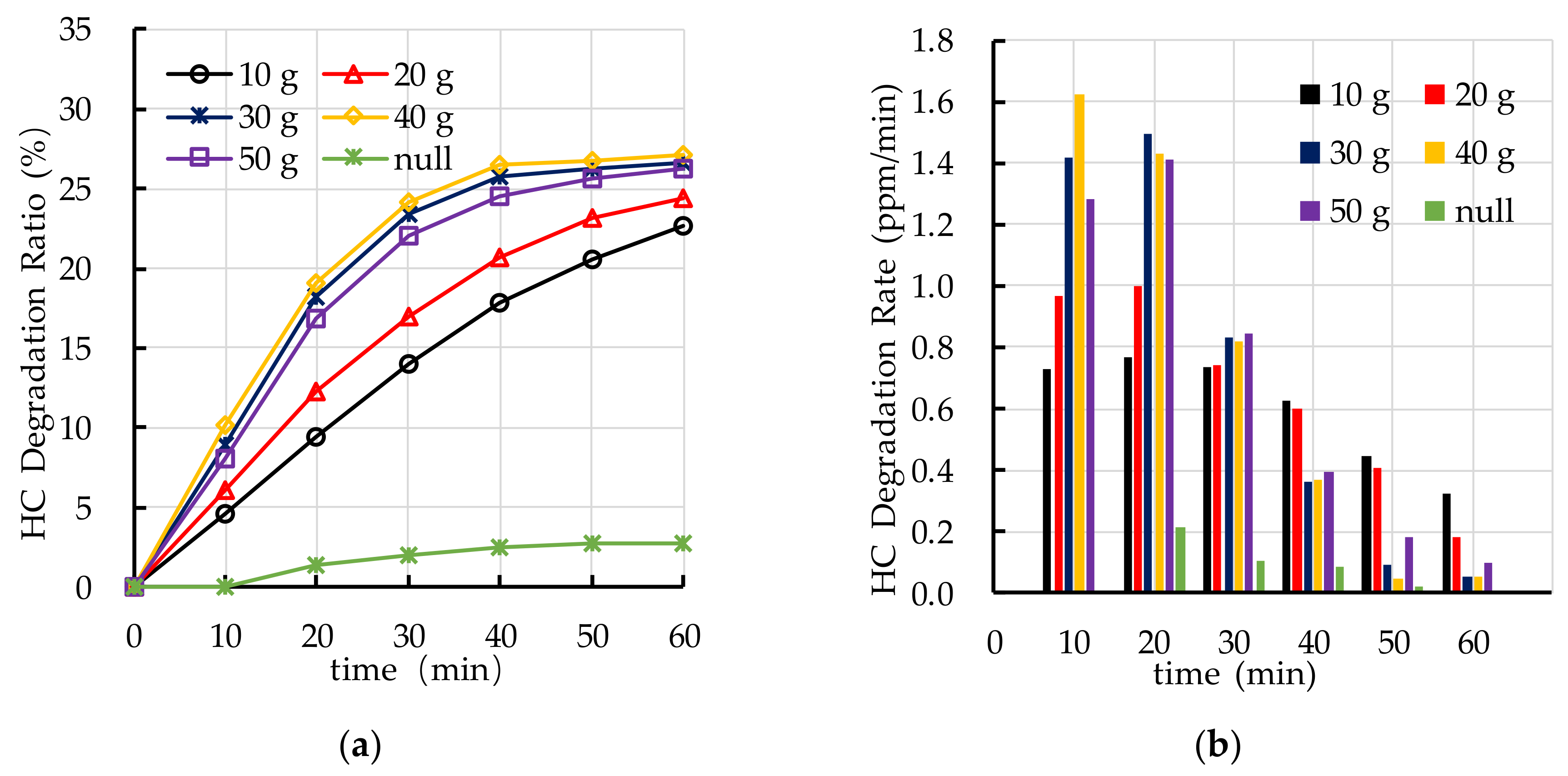
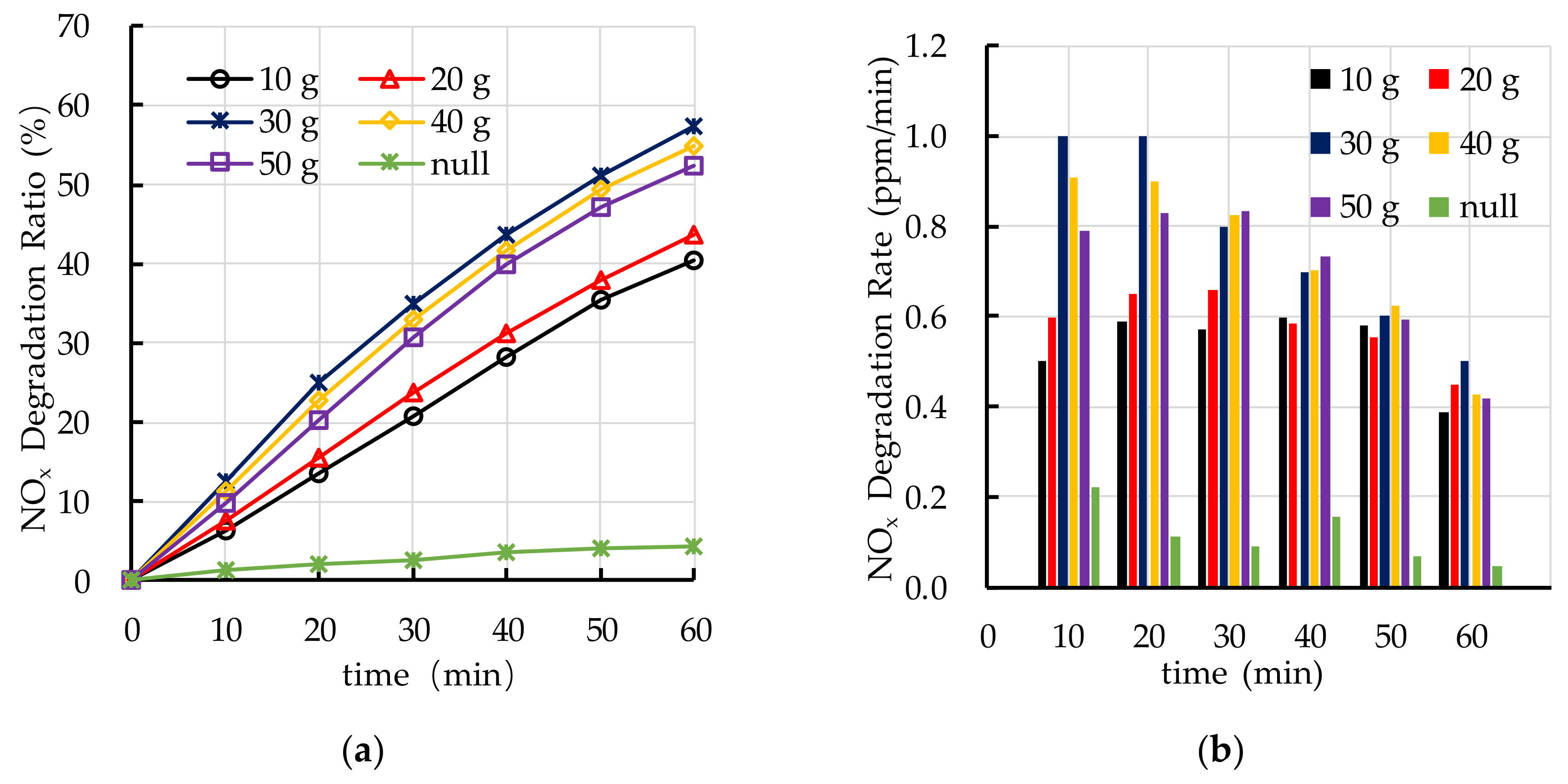
5.3. TiO2 Spraying Amount
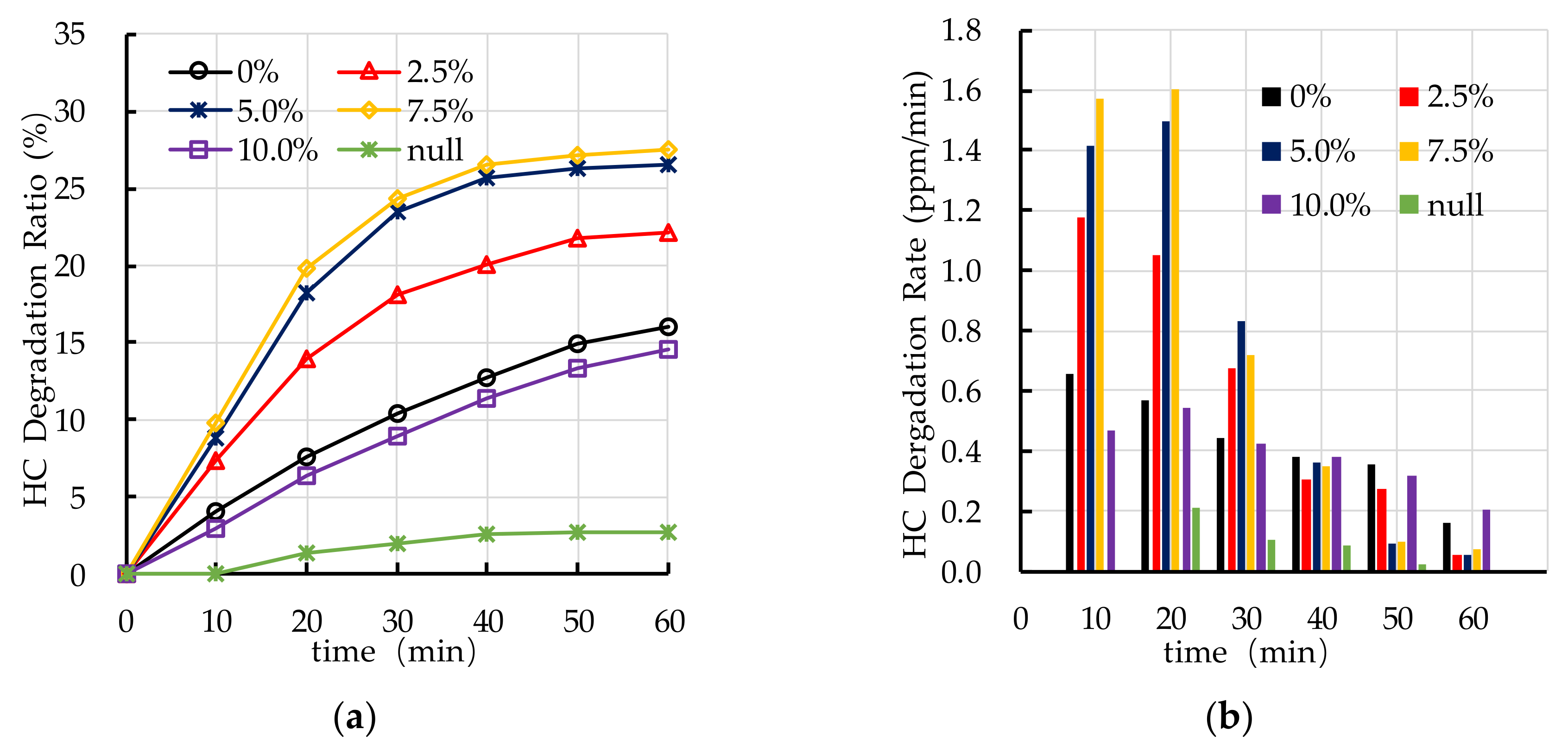
5.4. Dispersant Dosage
6. Conclusions
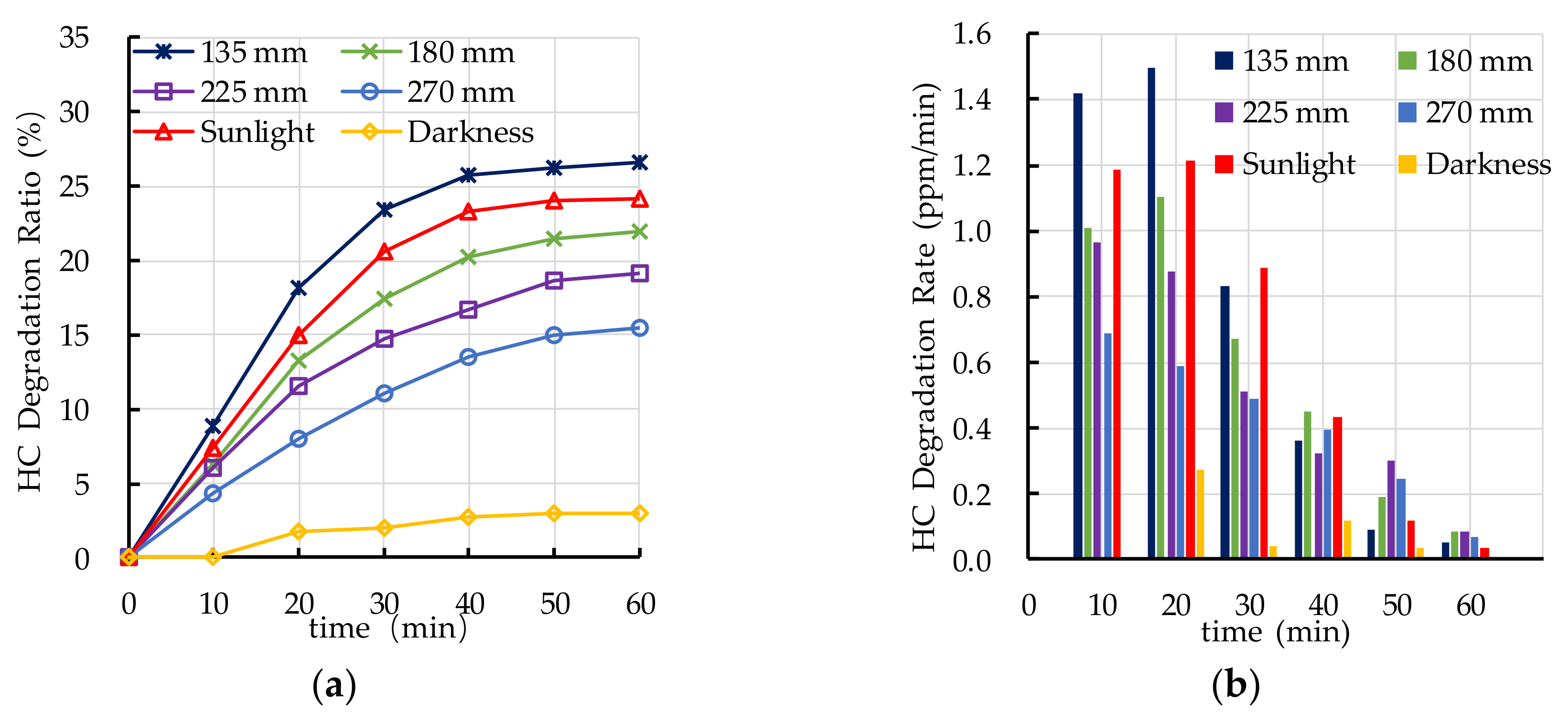
- Ultraviolet irradiation is needed as an elementary condition for the photocatalytic degradation reaction. The photocatalytic degradation ratio of automobile exhaust increases with the increase of ultraviolet irradiation intensity. The PEFPC can effectively degrade automobile exhaust and significantly improve urban air quality.
- The recommend nano TiO2 particle size is 25 nm. The most ideal TiO2 dosage and dispersant dosage are 10% and 5.0%, respectively. The optimal TiO2 spraying amount is 333.3 g/m2.
- The photocatalytic degradation of HC and NOx is different. The photocatalytic degradation of HC can be divided into two stages: rapid stage in the first 30 min and slow stage in the last 30 min. The photocatalytic degradation of NOx is relatively stable.
- The change in the photocatalytic ratio of PEFPC is consistent with the distribution area of nano TiO2 on the surface of the substrate materials. The contact area between nano TiO2 and ultraviolet light is a key factor affecting the photocatalytic performance of PEFPC.
Author Contributions
Funding
Acknowledgments
Conflicts of Interest
References
- Shu, Y.J.; Ji, J.; Xu, Y.; Deng, J.G.; Huang, H.B.; He, M.; Leung, D.Y.C.; Wu, M.Y.; Liu, S.W.; Liu, S.L.; et al. Promotional role of Mn doping on catalytic oxidation of VOCs over mesoporous TiO2 under vacuum ultraviolet (VUV) irradiation. Appl. Catal. B Environ. 2018, 220, 78–87. [Google Scholar] [CrossRef]
- Huang, H.B.; Lu, H.X.; Zhan, Y.J.; Liu, G.Y.; Feng, Q.Y.; Huang, H.L.; Mu, M.Y.; Ye, X.G. VUV photo-oxidation of gaseous benzene combined with ozone-assisted catalytic oxidation: Effect on transition metal catalyst. Appl. Surf. Sci. 2017, 391, 662–667. [Google Scholar] [CrossRef]
- Ângelo, J.; Andrade, L.; Madeira, L.M.; Mendes, A. An overview of photocatalysis phenomena applied to NOx abatement. J. Environ. Manag. 2013, 129, 522–539. [Google Scholar] [CrossRef]
- Čuček, L.; Klemeš, J.J.; Kravanja, Z. A Review of Footprint analysis tools for monitoring impacts on sustainability. J. Clean. Prod. 2019, 34, 9–20. [Google Scholar]
- Shen, S.H.; Burton, M.; Jobson, B.; Haselbach, L. Pervious concrete with titanium dioxide as a photocatalyst compound for a greener urban road environment. Constr. Build. Mater. 2012, 35, 874–883. [Google Scholar] [CrossRef]
- Nada, A.A.; Rouby, W.M.A.E.; Bekheet, M.F.; Antuch, M.; Weber, M.; Miele, P.; Viter, R.; Roualdes, S.; Millet, P.; Bechelany, M. Highly textured boron/nitrogen co-doped TiO2 with honeycomb structure showing enhanced visible-light photoelectrocatalytic activity. Appl. Sure Sci. 2020, 505, 144419. [Google Scholar] [CrossRef]
- Nada, A.A.; Bekheet, M.F.; Viter, R.; Roualdes, S.; Bechelany, M. BN/GdxTi(1-x)O(4-x)/2 nanofibers for enhanced photocatalytic hydrogen production under visible light. Appl. Catal. B Environ. 2019, 251, 76–86. [Google Scholar] [CrossRef]
- Koca, M.; Kudas, Z.; Ekinci, D.; Aydoğan, S. Performance improvement of n-TiO2/p-Si heterojunction by forming of n-TiO2/polyphenylene/p-Si anisotype sandwich heterojunction. Mat. Sci. ESEMicon. Proc. 2020, 121, 105436. [Google Scholar] [CrossRef]
- Bianchi, C.L.; Gatto, S.; Piroal, C.; Naldoni, A.; Michele, A.D.; Gerrato, G.; Crocellà, V.; Capucci, V. Photocatalytic degradation of acetone, acetaldehyde and toluene in gas-phase: Comparison between nano and micro-sized TiO2. Appl. Catal. B Environ. 2014, 146, 123–130. [Google Scholar] [CrossRef]
- Fu, P.F.; Zhang, P.Y.; Li, J. Photocatalytic degradation of low concentration formaldehyde and simultaneous elimination of ozone by-product using palladium modified TiO2 films under UV 254+185nm irradiation. Appl. Catal. B Environ. 2011, 105, 220–228. [Google Scholar] [CrossRef]
- Jo, W.K.; Kim, J.T. Application of visible-light photocatalysis with nitrogen-doped or unmodified titanium dioxide for control of indoor-level volatile organic compounds. J. Hazard. Mater. 2009, 164, 360–366. [Google Scholar] [CrossRef] [PubMed]
- Guo, M.Z.; Poon, C.S. Photocatalytic NO removal of concrete surface layers intermixed with TiO2. Build. Environ. 2013, 70, 102–109. [Google Scholar] [CrossRef]
- Chen, J.; Poon, C.S. Photocatalytic activity of titanium dioxide modified concrete materials– Influence of utilizing recycled glass cullets as aggregates. J. Environ. Manag. 2009, 90, 3436–3442. [Google Scholar] [CrossRef] [PubMed]
- Wang, H.M.; Xie, D.; Chen, Q.; You, C.F. Kinetic modeling for the deactivation of TiO2 during the photocatalytic removal of low concentration SO2. Chem. Eng. J. 2016, 303, 425–432. [Google Scholar] [CrossRef]
- Shayegan, Z.; Lee, C.S.; Haghighat, F. TiO2 photocatalyst for removal of volatile organic compounds in gas phase –A review. Chem. Eng. J. 2018, 334, 2408–2439. [Google Scholar] [CrossRef]
- Yahia, A.; Kabagire, K.D. New approach to proportion pervious concrete. Constr. Build. Mater. 2014, 62, 38–46. [Google Scholar] [CrossRef]
- Shen, W.G.; Zhang, C.; Li, Q.; Zhang, W.S.; Cao, L.; Ye, J.Y. Preparation of titanium dioxide nano particle modified photocatalytic self-cleaning concrete. J. Clean. Prod. 2015, 87, 762–765. [Google Scholar] [CrossRef]
- Ballari, M.M.; Hunger, M.; Husken, G.; Brouwers, H.J.H. NOx photocatalytic degradation employing concrete pavement containing titanium dioxide. Appl. Catal. B Environ. 2010, 95, 245–254. [Google Scholar] [CrossRef]
- Ballari, M.M.; Yu, Q.L.; Brouwers, H.J.H. Experimental study of the NO and NO2 degradation by photocatalytically active concrete. Catal. Today 2011, 161, 175–180. [Google Scholar] [CrossRef]
- Henderson, M.A. A surface science perspective on TiO2 photocatalysis. Surf. Sci. Rep. 2011, 66, 185–297. [Google Scholar] [CrossRef]
- Guo, M.Z.; Ling, T.C.; Poon, C.S. Nano-TiO2-based architectural mortar for NO removal and bacteria inactivation: Influence of coating and weathering conditions. Cement Concrete Comp. 2013, 36, 101–108. [Google Scholar] [CrossRef]
- Nolam, N.T.; Seery, M.K.; Pillai, S.C. Spectroscopic Investigation of the Anatase-to-Rutile Transformation of Sol-Gel-Synthesized TiO2 Photocatalysts. J. Phys. Chem. C 2009, 113, 16151–16157. [Google Scholar] [CrossRef]
- Fischer, K.; Gawel, A.; Rosen, D.; Krause, M.; Latif, A.A.; Griebel, J.; Prager, A.; Schulze, A. Low-Temperature Synthesis of Anatase/Rutile/Brookite TiO2 Nanoparticles on a Polymer Membrane for Photocatalysis. Catalysts 2017, 7, 209. [Google Scholar] [CrossRef]
- Monai, M.; Montini, T.; Fornasiero, P. Brookite: Nothing New under the Sun ? Catalysts 2017, 7, 304. [Google Scholar] [CrossRef] [Green Version]
- Xu, Y.D.; Chen, W.; Jin, R.Y.; Shen, J.S.; Smallbone, K.; Yan, C.Y.; Hu, L. Experimental investigation of photocatalytic effects of concrete in air purification adopting entire concrete waste reuse model. J. Hazard. Mater. 2018, 353, 421–430. [Google Scholar] [CrossRef]
- Guo, M.Z.; Ling, T.C.; Poon, C.S. Photocatalytic NOx degradation of concrete surface layers intermixed and spray-coated with nano-TiO2: Influence of experimental factors. Cement. Concr. Comp. 2017, 83, 279–289. [Google Scholar] [CrossRef]
- Dalton, J.S.; Janes, P.A.; Jones, N.G.; Nicholson, J.A.; Hallam, K.R.; Allen, G.C. Photocatalytic oxidation of NOx gases using TiO2: A surface spectroscopic approach. Environ. Pollut. 2002, 120, 415–422. [Google Scholar] [CrossRef]
- Chen, J.; Poon, C.S. Photocatalytic construction and building materials: From fundamentals to applications. Build. Environ. 2009, 44, 1899–1906. [Google Scholar] [CrossRef]
- Wu, Y.; Zhao, J.Z.; Li, Y.; Lu, K. Preparation and freezing behavior of TiO2 nanoparticle suspensions. Ceram. Int. 2016, 42, 15597–15602. [Google Scholar] [CrossRef]
- Ministry of Housing and Urban-Rural Development of the People’s Republic of China. Technical Specifications for Pervious Concrete Pavement; Ministry of Housing and Urban-Rural Development of the People’s Republic of China: Beijing, China, 2009. (In Chinese) [Google Scholar]
- Liu, H.B.; Luo, G.B.; Wei, H.B.; Yu, H. Strength, permeability, and freeze-thaw durability of pervious concrete with different aggregate sizes, porosities, and water-binder ratios. Appl. Sci. 2018, 8, 1217. [Google Scholar] [CrossRef] [Green Version]
- Liu, H.B.; Luo, G.B.; Gong, Y.F.; Wei, H.B. Mechanical properties, permeability, and freeze–thaw resistance of pervious concrete modified by waste crumb rubbers. Appl. Sci. 2018, 8, 1843. [Google Scholar] [CrossRef] [Green Version]
- Kmat, P.V. Photochemistry on Nonreactive and Reactive (ESEMiconductor) Surfaces. Chem. Rev. 1993, 93, 267–300. [Google Scholar] [CrossRef]


| Material | Chemical Composition (%) | |||||
|---|---|---|---|---|---|---|
| SiO2 | Al2O3 | Fe2O3 | CaO | MgO | SO3 | |
| Cement | 22.60 | 5.60 | 4.30 | 62.70 | 1.70 | 2.50 |
| Mix ID | TiO2 Particle Size (nm) | TiO2 Dosage (%) | TiO2 (g) | TiO2 Spraying Amount 1 (g/m2) | TiO2 Spraying Amount (g) | Dispersant Dosage (%) | Dispersant (g) |
|---|---|---|---|---|---|---|---|
| PZ1 | 10 | 10 | 3.0 | 333.3 | 30 | 5.0 | 0.150 |
| PZ2 | 25 | 10 | 3.0 | 333.3 | 30 | 5.0 | 0.150 |
| PZ3 | 50 | 10 | 3.0 | 333.3 | 30 | 5.0 | 0.150 |
| D1 | 25 | 3 | 0.9 | 333.3 | 30 | 5.0 | 0.045 |
| D2 | 25 | 5 | 1.5 | 333.3 | 30 | 5.0 | 0.075 |
| D3 | 25 | 10 | 3.0 | 333.3 | 30 | 5.0 | 0.150 |
| D4 | 25 | 15 | 4.5 | 333.3 | 30 | 5.0 | 0.225 |
| D5 | 25 | 20 | 6.0 | 333.3 | 30 | 5.0 | 0.300 |
| SD1 | 25 | 10 | 1.0 | 111.1 | 10 | 5.0 | 0.050 |
| SD2 | 25 | 10 | 2.0 | 222.2 | 20 | 5.0 | 0.100 |
| SD3 | 25 | 10 | 3.0 | 333.3 | 30 | 5.0 | 0.150 |
| SD4 | 25 | 10 | 4.0 | 444.4 | 40 | 5.0 | 0.200 |
| SD5 | 25 | 10 | 5.0 | 555.5 | 50 | 5.0 | 0.250 |
| DD1 | 25 | 10 | 3.0 | 333.3 | 30 | 0 | 0 |
| DD2 | 25 | 10 | 3.0 | 333.3 | 30 | 2.5 | 0.075 |
| DD3 | 25 | 10 | 3.0 | 333.3 | 30 | 5.0 | 0.150 |
| DD4 | 25 | 10 | 3.0 | 333.3 | 30 | 7.5 | 0.225 |
| DD5 | 25 | 10 | 3.0 | 333.3 | 30 | 10.0 | 0.300 |
| LR1 | 25 | 10 | 3.0 | 333.3 | 30 | 5.0 | 0.150 |
| LR2 | 25 | 10 | 3.0 | 333.3 | 30 | 5.0 | 0.150 |
| LR3 | 25 | 10 | 3.0 | 333.3 | 30 | 5.0 | 0.150 |
| LR4 | 25 | 10 | 3.0 | 333.3 | 30 | 5.0 | 0.150 |
| Null | 333.3 | 30 |
| Light Source | UV Height 135 mm | UV Height 180 mm | UV Height 225 mm | UV Height 270 mm | Sunlight |
|---|---|---|---|---|---|
| Ultraviolet irradiation intensity (μW/cm2) | 105.1 | 48.4 | 31.8 | 19.1 | 104.9 |
Publisher’s Note: MDPI stays neutral with regard to jurisdictional claims in published maps and institutional affiliations. |
© 2020 by the authors. Licensee MDPI, Basel, Switzerland. This article is an open access article distributed under the terms and conditions of the Creative Commons Attribution (CC BY) license (http://creativecommons.org/licenses/by/4.0/).
Share and Cite
Luo, G.; Liu, H.; Li, W.; Lyu, X. Automobile Exhaust Removal Performance of Pervious Concrete with Nano TiO2 under Photocatalysis. Nanomaterials 2020, 10, 2088. https://doi.org/10.3390/nano10102088
Luo G, Liu H, Li W, Lyu X. Automobile Exhaust Removal Performance of Pervious Concrete with Nano TiO2 under Photocatalysis. Nanomaterials. 2020; 10(10):2088. https://doi.org/10.3390/nano10102088
Chicago/Turabian StyleLuo, Guobao, Hanbing Liu, Wenjun Li, and Xiang Lyu. 2020. "Automobile Exhaust Removal Performance of Pervious Concrete with Nano TiO2 under Photocatalysis" Nanomaterials 10, no. 10: 2088. https://doi.org/10.3390/nano10102088