
INSUS: Indoor Navigation System Using Unity and Smartphone for User Ambulation Assistance
 , , ,
, , ,
Abstract
:1. Introduction
2. Preliminaries
2.1. Indoor Localization by Wireless
2.1.1. Multilateration Method
2.1.2. Fingerprinting Method
2.2. Localization by SLAM Technique
2.3. 3D Modelling Techniques
2.4. Indoor Map Path Planning Techniques
2.5. User Interface
2.6. REST API
3. Comparing INSUS Techniques with Others Systems
3.1. Comparison of Techniques Used in Indoor Navigation System
3.2. Comparing of Characteristics in Indoor Navigation Products
- Adaptive UI: indicates the capability of the system to use suitable UI for viewing navigation as well as the path.
- Walk-in Navigation: indicates the capability to navigate while also walking.
- Zero Additional Devices: indicates the system operates without any additional devices.
- Path Guidelines: indicates the capability of identifying and displaying the most efficient path from the user’s current location to the intended destination.
- Multistory Navigation: indicates the capability of providing multi-floor navigation.
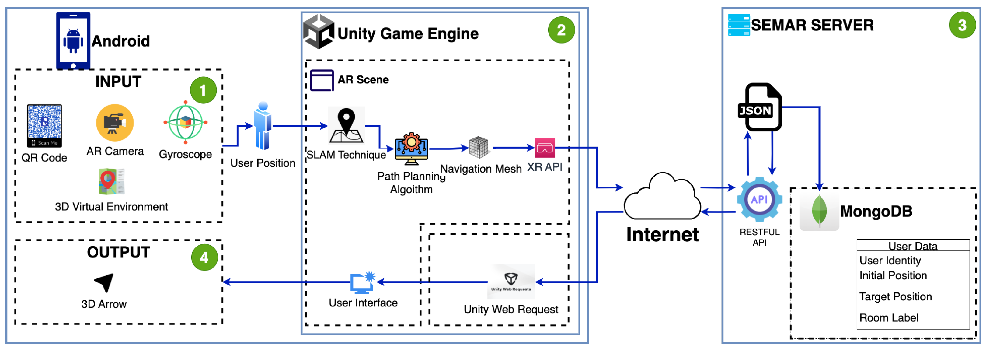
4. System Design
4.1. Overview
4.2. Input
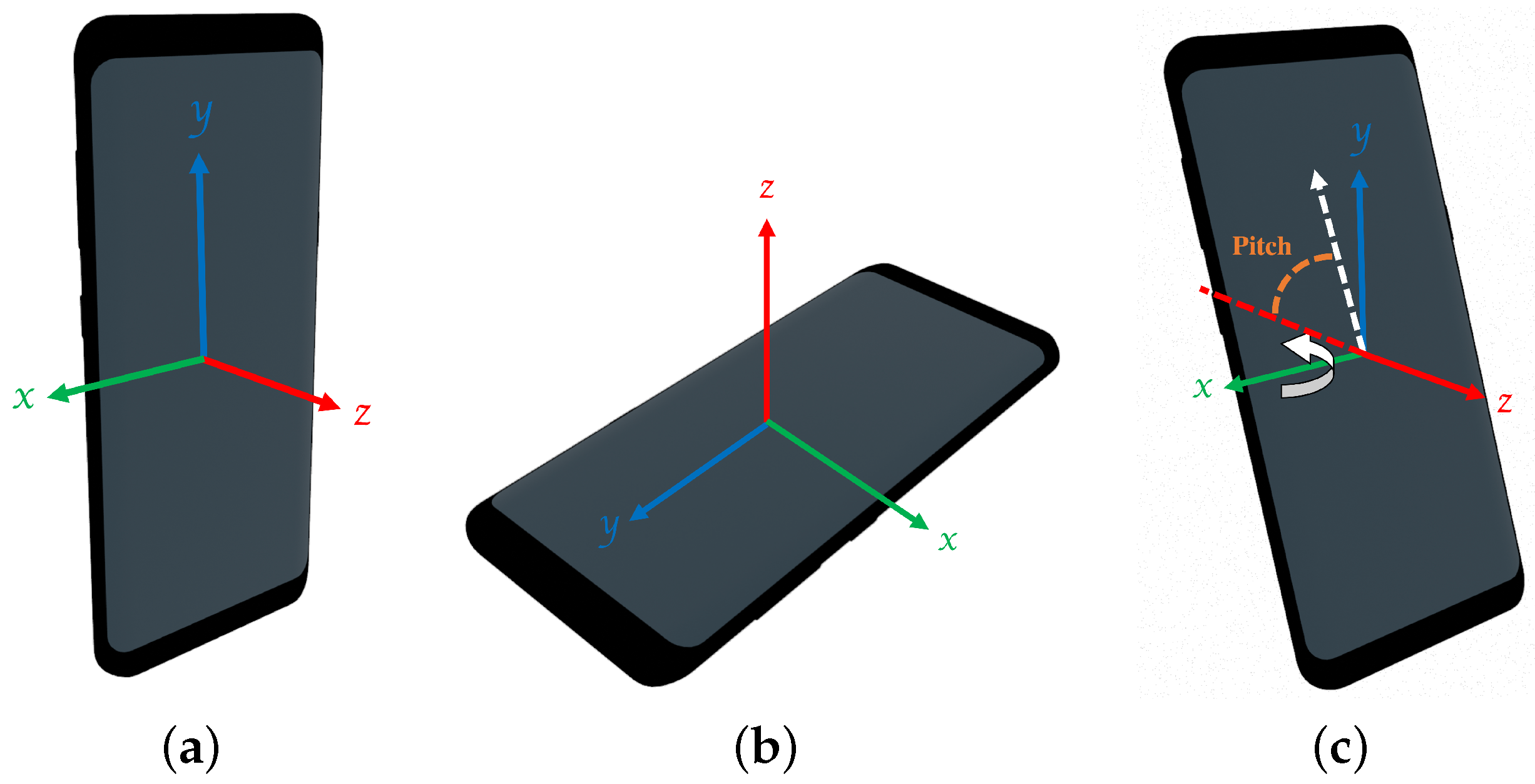
4.2.1. Gyroscope
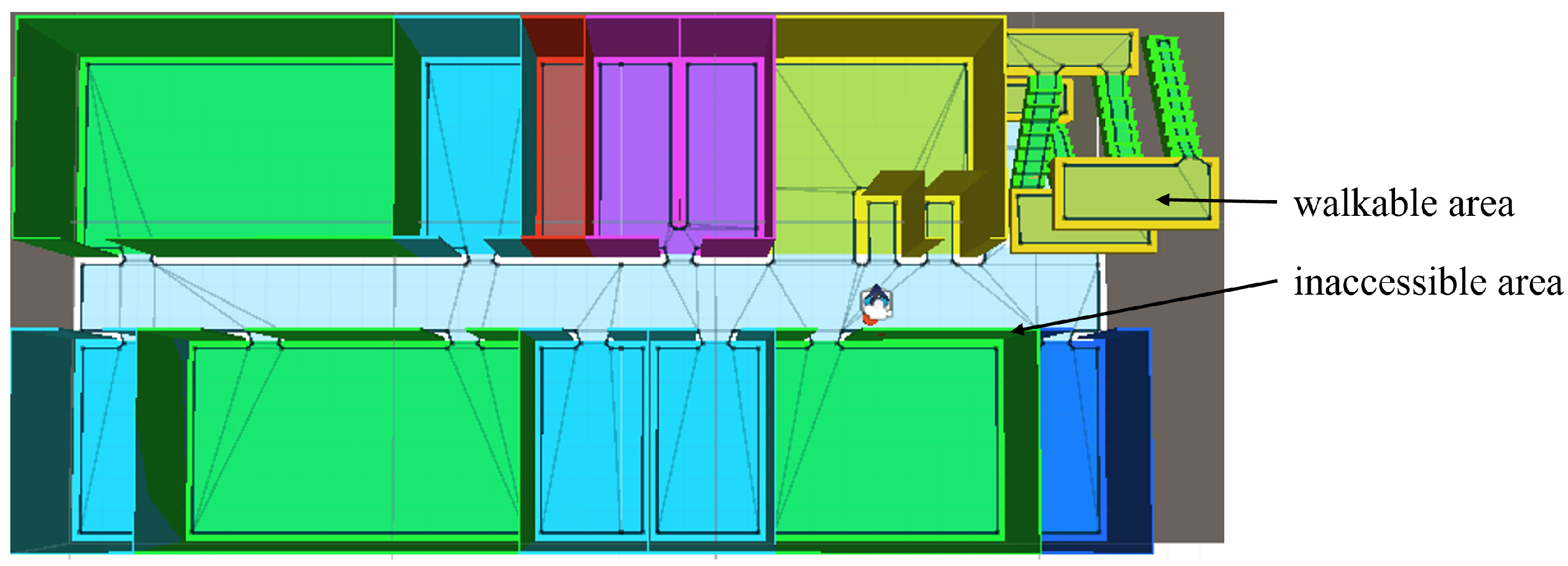
4.2.2. 3D Virtual Environment
4.2.3. AR Camera
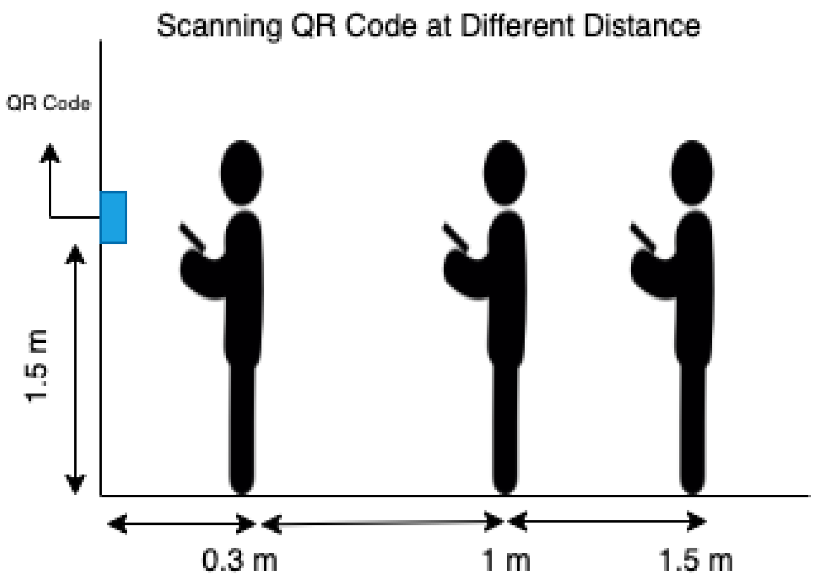
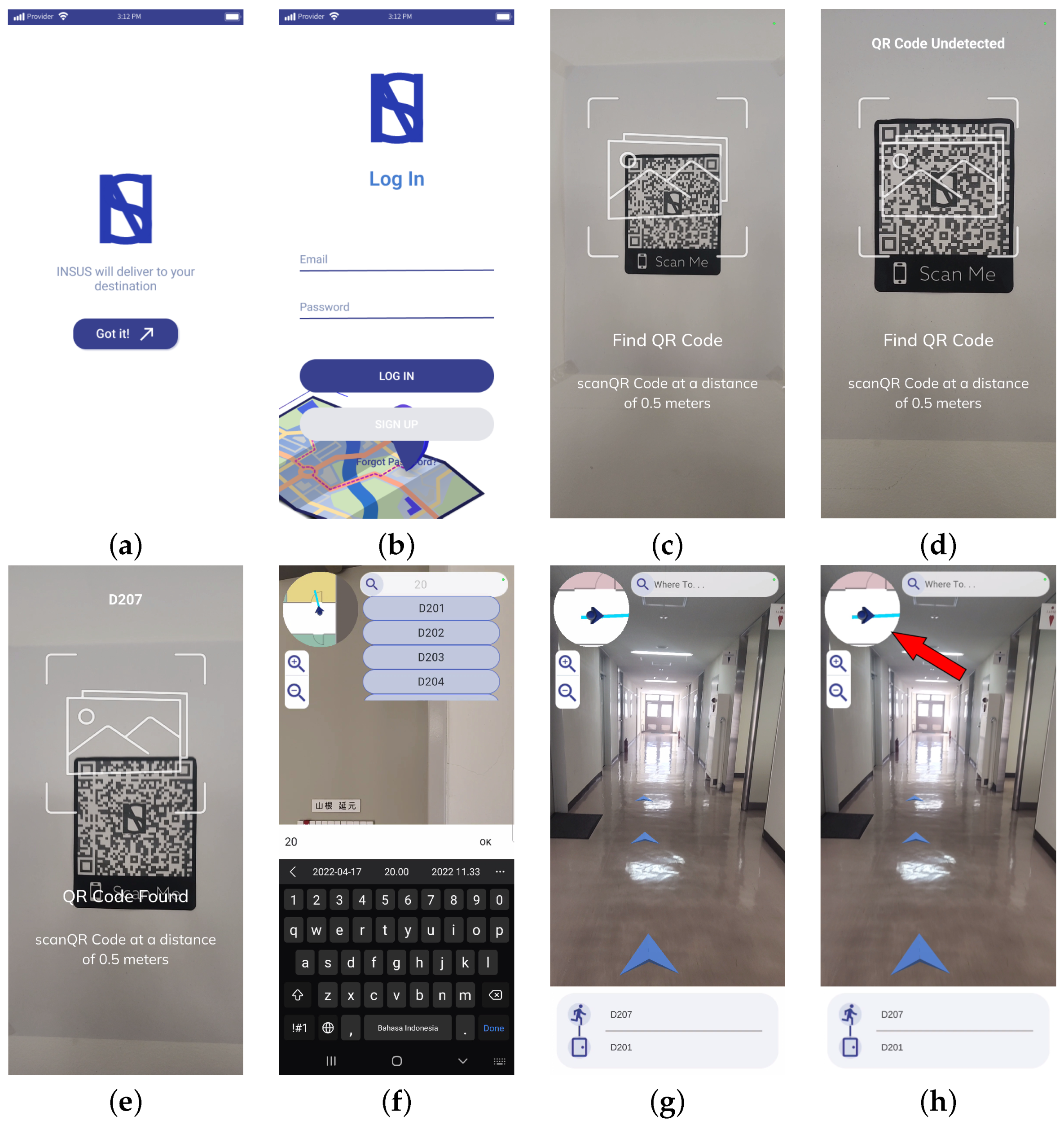
4.2.4. QR Code
| Algorithm 1: Pseudocode for Scanning QR code |
| Ensure: |
| whiledo |
| if then |
| print “n room detected” |
| else |
| print “unrecognized room label” |
4.3. User Position
4.4. Unity
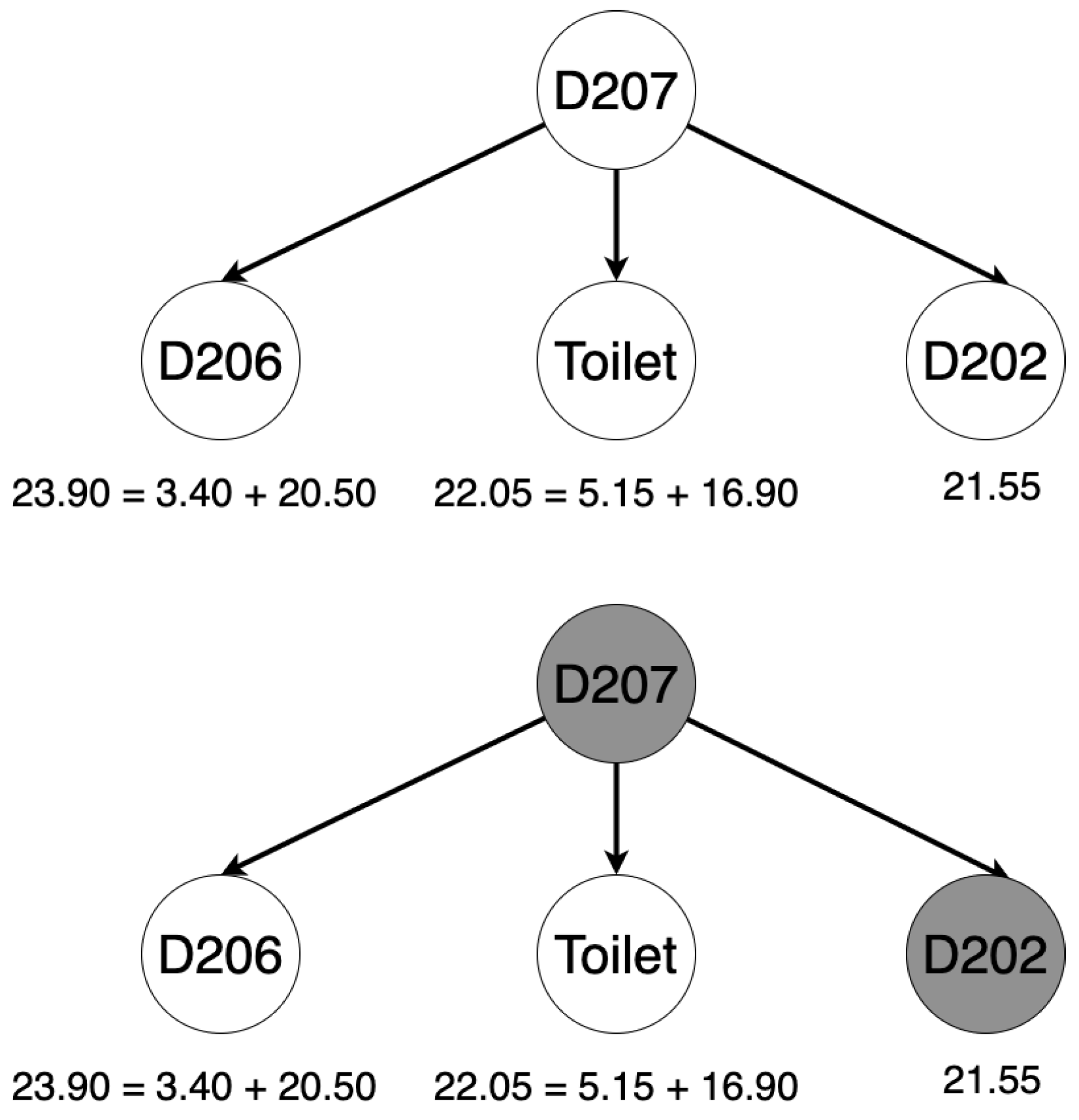
4.4.1. Pathfinding

4.4.2. AR Scene
4.4.3. User Interface
4.4.4. Unity Web Request
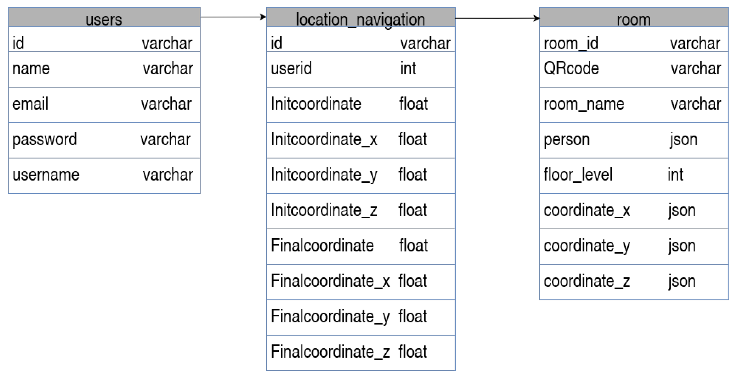
4.5. SEMAR Server
4.6. Output
4.7. User Experience Measurement
5. Evaluation and Discussion
5.1. Device Requirements and Scenario
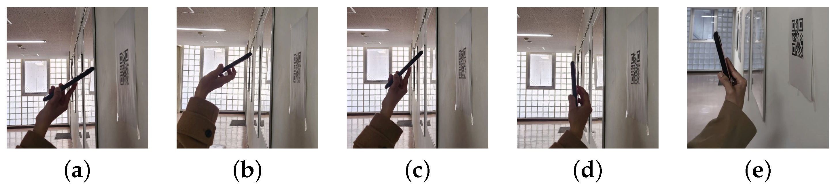
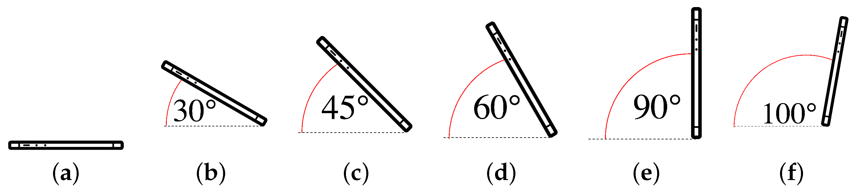
5.2. QR Code Scanning Practice
5.3. Navigation Accuracy
5.4. User Experience
6. Conclusions
Author Contributions
Funding
Data Availability Statement
Conflicts of Interest
References
- Sáez, Y.; Montes, H.; Garcia, A.; Muñoz, J.; Collado, E.; Mendoza, R. Indoor Navigation Technologies Based on RFID Systems to Assist Visually Impaired People: A Review and a Proposal. IEEE Lat. Am. Trans. 2021, 19, 1286–1298. [Google Scholar] [CrossRef]
- Li, N.; Guan, L.; Gao, Y.; Du, S.; Wu, M.; Guang, X.; Cong, X. Indoor and outdoor low-cost seamless integrated navigation system based on the integration of INS/GNSS/Lidar System. Remote Sens. 2020, 12, 3271. [Google Scholar] [CrossRef]
- Anjum, M.; Abdullah Khan, M.; Hassan, S.A.; Jung, H.; Dev, K. Analysis of time-weighted Lora-based positioning using machine learning. Comput. Commun. 2022, 193, 266–278. [Google Scholar] [CrossRef]
- Li, Y.; Zhuang, Y.; Hu, X.; Gao, Z.; Hu, J.; Chen, L.; He, Z.; Pei, L.; Chen, K.; Wang, M.; et al. Location-Enabled IoT (LE-IoT): A Survey of Positioning Techniques, Error Sources, and Mitigation. arXiv 2020, arXiv:2004.03738. [Google Scholar]
- Nessa, A.; Adhikari, B.; Hussain, F.; Fernando, X.N. A Survey of Machine Learning for Indoor Positioning. IEEE Access 2020, 8, 214945–214965. [Google Scholar] [CrossRef]
- Zhang, Z.; Du, H.; Choi, S.; Cho, S.H. TIPS: Transformer Based Indoor Positioning System Using Both CSI and DoA of WiFi Signal. IEEE Access 2022, 10, 111363–111376. [Google Scholar] [CrossRef]
- Gadhgadhi, A.; Hachaichi, Y.; Zairi, H. A machine learning based indoor localization. In Proceedings of the 2020 4th International Conference on Advanced Systems and Emergent Technologies (IC_ASET), Hammamet, Tunisia, 15–18 December 2020. [Google Scholar] [CrossRef]
- Rustagi, T.; Yoo, K. Indoor AR navigation using tilesets. In Proceedings of the 24th ACM Symposium on Virtual Reality Software and Technology, Tokyo, Japan, 28 November–1 December 2018; pp. 1–2. [Google Scholar]
- Selin, E. 10 Different Types of 3D Modeling Techniques. 2021. Available online: https://artisticrender.com/10-different-types-of-3d-modeling-techniques/ (accessed on 2 February 2023).
- Asraf, O.; Shama, F.; Klein, I. PDRNet: A Deep-Learning Pedestrian Dead Reckoning Framework. IEEE Sensors J. 2022, 22, 4932–4939. [Google Scholar] [CrossRef]
- Zhou, Z.; Feng, W.; Li, P.; Liu, Z.; Xu, X.; Yao, Y. A fusion method of pedestrian dead reckoning and pseudo indoor plan based on conditional random field. Measurement 2023, 207, 112417. [Google Scholar] [CrossRef]
- Zhao, J.; Xu, Q.; Zlatanova, S.; Liu, L.; Ye, C.; Feng, T. Weighted octree-based 3D indoor pathfinding for multiple locomotion types. Int. J. Appl. Earth Obs. Geoinf. 2022, 112, 102900. [Google Scholar] [CrossRef]
- Chidsin, W.; Gu, Y.; Goncharenko, I. AR-based navigation using RGB-D camera and hybrid map. Sustainability 2021, 13, 5585. [Google Scholar] [CrossRef]
- Chu, E.T.H.; Wang, S.C.; Chang, C.C.; Liu, J.W.S.; Hsu, J.; Wu, H.M. WPIN: A waypoint-based indoor navigation system. In Proceedings of the IPIN (Short Papers/Work-in-Progress Papers), Pisa, Italy, 30 September–3 October 2019; pp. 187–194. [Google Scholar]
- Wichmann, J. Indoor positioning systems in hospitals: A scoping review. Digit. Health 2022, 8, 20552076221081696. [Google Scholar] [CrossRef]
- Mackey, A.; Spachos, P.; Plataniotis, K.N. Enhanced Indoor Navigation System with beacons and Kalman filters. In Proceedings of the 2018 IEEE Global Conference on Signal and Information Processing (GlobalSIP), Anaheim, CA, USA, 26–29 November 2018. [Google Scholar] [CrossRef]
- Sangthong, J. The indoor navigation using mapping technique based on signal strength difference. In Proceedings of the 2018 21st International Symposium on Wireless Personal Multimedia Communications (WPMC), Chiang Rai, Thailand, 25–28 November 2018. [Google Scholar] [CrossRef]
- De Oliveira, L.S.; Rayel, O.K.; Leitao, P. Low-cost indoor localization system combining multilateration and kalman filter. In Proceedings of the 2021 IEEE 30th International Symposium on Industrial Electronics (ISIE), Kyoto, Japan, 20–23 June 2021; IEEE: Piscataway, NJ, USA, 2021; pp. 1–6. [Google Scholar]
- Guidara, A.; Derbel, F.; Fersi, G.; Bdiri, S.; Jemaa, M.B. Energy-efficient on-demand indoor localization platform based on wireless sensor networks using low power wake up receiver. Ad Hoc Netw. 2019, 93, 101902. [Google Scholar] [CrossRef]
- Ashraf, I.; Hur, S.; Park, Y. Smartphone sensor based indoor positioning: Current status, opportunities, and future challenges. Electronics 2020, 9, 891. [Google Scholar] [CrossRef]
- Huang, H.; Zeng, Q.; Chen, R.; Meng, Q.; Wang, J.; Zeng, S. Seamless navigation methodology optimized for indoor/outdoor detection based on WIFI. In Proceedings of the 2018 Ubiquitous Positioning, Indoor Navigation and Location-Based Services (UPINLBS), Wuhan, China, 22–23 March 2018. [Google Scholar] [CrossRef]
- Puspitaningayu, P.; Funabiki, N.; Huo, Y.; Hamazaki, K.; Kuribayashi, M.; Kao, W.C. Application of fingerprint-based indoor localization system using IEEE 802.15.4 to two-floors environment. In Proceedings of the 2022 IEEE 4th Global Conference on Life Sciences and Technologies (LifeTech), Osaka, Japan, 7–9 March 2022. [Google Scholar] [CrossRef]
- Huo, Y.; Puspitaningayu, P.; Funabiki, N.; Hamazaki, K.; Kuribayashi, M.; Kojima, K. A proposal of the fingerprint optimization method for the fingerprint-based indoor localization system with IEEE 802.15.4 devices. Information 2022, 13, 211. [Google Scholar] [CrossRef]
- Polak, L.; Rozum, S.; Slanina, M.; Bravenec, T.; Fryza, T.; Pikrakis, A. Received signal strength fingerprinting-based indoor location estimation employing machine learning. Sensors 2021, 21, 4605. [Google Scholar] [CrossRef] [PubMed]
- Sinha, R.S.; Hwang, S.H. Comparison of CNN applications for RSSI-based fingerprint indoor localization. Electronics 2019, 8, 989. [Google Scholar] [CrossRef] [Green Version]
- Chen, C.H.; Chen, P.W.; Chen, P.J.; Liu, T.H. Indoor Positioning Using Magnetic Fingerprint Map Captured by Magnetic Sensor Array. Sensors 2021, 21, 5707. [Google Scholar] [CrossRef]
- Deng, Y.; Ai, H.; Deng, Z.; Gao, W.; Shang, J. An overview of indoor positioning and mapping technology standards. Standards 2022, 2, 157–183. [Google Scholar] [CrossRef]
- Gerstweiler, G.; Vonach, E.; Kaufmann, H. Hymotrack: A Mobile AR navigation system for complex indoor environments. Sensors 2015, 16, 17. [Google Scholar] [CrossRef] [Green Version]
- Zou, Q.; Sun, Q.; Chen, L.; Nie, B.; Li, Q. A Comparative Analysis of LiDAR SLAM-Based Indoor Navigation for Autonomous Vehicles. IEEE Trans. Intell. Transp. Syst. 2022, 23, 6907–6921. [Google Scholar] [CrossRef]
- El Barhoumi, N.; Hajji, R.; Bouali, Z.; Ben Brahim, Y.; Kharroubi, A. Assessment of 3D Models Placement Methods in Augmented Reality. Appl. Sci. 2022, 12, 10620. [Google Scholar] [CrossRef]
- Prithal. Different Types of 3D Modelling. 2021. Available online: https://xo3d.co.uk/different-types-of-3d-modelling/ (accessed on 23 January 2023).
- Balado, J.; Díaz-Vilariño, L.; Arias, P.; Frías, E. Point clouds to direct indoor pedestrian pathfinding. Int. Arch. Photogramm. Remote Sens. Spat. Inf. Sci. W13. [CrossRef] [Green Version]
- Candra, A.; Budiman, M.A.; Hartanto, K. Dijkstra’s and A-Star in Finding the Shortest Path: A Tutorial. In Proceedings of the 2020 International Conference on Data Science, Artificial Intelligence, and Business Analytics (DATABIA), Medan, Indonesia, 16–17 July 2020; pp. 28–32. [Google Scholar] [CrossRef]
- Gan, Q.; Liu, Z.; Liu, T.; Chai, Y. An indoor evacuation guidance system with an AR virtual agent. Procedia Comput. Sci. 2022, 213, 636–642. [Google Scholar] [CrossRef]
- Ehsan, A.; Abuhaliqa, M.A.; Catal, C.; Mishra, D. RESTful API testing methodologies: Rationale, challenges, and solution directions. Appl. Sci. 2022, 12, 4369. [Google Scholar] [CrossRef]
- Wang, X.; Qin, D.; Guo, R.; Zhao, M.; Ma, L.; Berhane, T.M. The technology of crowd-sourcing landmarks-assisted smartphone in indoor localization. IEEE Access 2020, 8, 57036–57048. [Google Scholar] [CrossRef]
- Navin. Indoor and Outdoor Navigation. 2013. Available online: https://nav-in.com/ (accessed on 5 February 2023).
- IndoorAtlas. Indooratlas API Documentation. 2012. Available online: https://docs.indooratlas.com/apidocs/ (accessed on 5 February 2023).
- InMapz. Inmapz Home. 2016. Available online: https://inmapz.com/ (accessed on 5 February 2023).
- Situm. 01—Introduction Archives. 2014. Available online: https://situm.com/docs-category/changelogs/ (accessed on 7 February 2023).
- Google. Google Indoor Map. 2018. Available online: https://www.google.com/maps/about/partners/indoormaps (accessed on 5 February 2023).
- Lemoyne, R.; Mastroianni, T. Implementation of a Smartphone as a Wearable and Wireless Gyroscope Platform for Machine Learning Classification of Hemiplegic Gait Through a Multilayer Perceptron Neural Network. In Proceedings of the 2018 17th IEEE International Conference on Machine Learning and Applications (ICMLA), Orlando, FL, USA, 17–20 December 2018; pp. 946–950. [Google Scholar] [CrossRef]
- Taira, G.M.N.; Sementille, A.C.; Sanches, S.R.R. Influence of the Camera Viewpoint on Augmented Reality Interaction. IEEE Lat. Am. Trans. 2018, 16, 260–264. [Google Scholar] [CrossRef] [Green Version]
- Tang, F.; Wu, Y.; Hou, X.; Ling, H. 3D Mapping and 6D Pose Computation for Real Time Augmented Reality on Cylindrical Objects. IEEE Trans. Circuits Syst. Video Technol. 2020, 30, 2887–2899. [Google Scholar] [CrossRef]
- Chou, G.J.; Wang, R.Z. The Nested QR Code. IEEE Signal Process. Lett. 2020, 27, 1230–1234. [Google Scholar] [CrossRef]
- Eugênio Gonçalves, H.; Xavier Medeiros, L.; Coutinho Mateus, A. Algorithm for Locating the Vertices of a QR Code and Removing Perspective. IEEE Lat. Am. Trans. 2021, 19, 1933–1940. [Google Scholar] [CrossRef]
- Huang, P.C.; Chang, C.C.; Li, Y.H.; Liu, Y. Efficient QR Code Secret Embedding Mechanism Based on Hamming Code. IEEE Access 2020, 8, 86706–86714. [Google Scholar] [CrossRef]
- GoogleDeveloper. Fundamental Concepts/ARcore/GoogleDeveloper. Available online: https://developers.google.com/ar/develop/fundamentals (accessed on 5 February 2023).
- Iqbal, M.W.; Ch, N.A.; Shahzad, S.K.; Naqvi, M.R.; Khan, B.A.; Ali, Z. User Context Ontology for Adaptive Mobile-Phone Interfaces. IEEE Access 2021, 9, 96751–96762. [Google Scholar] [CrossRef]
- Panduman, Y.Y.; Funabiki, N.; Puspitaningayu, P.; Kuribayashi, M.; Sukaridhoto, S.; Kao, W.C. Design and implementation of SEMAR IOT server platform with applications. Sensors 2022, 22, 6436. [Google Scholar] [CrossRef] [PubMed]


| Virtual Location [28] | Fingerprinting [22] | Image Matching [36] | Multilateration [14] | |
|---|---|---|---|---|
| Accuracy | HIGH | HIGH | MODERATE | HIGH |
| Consistency | MODERATE | HIGH | LOW | MODERATE |
| Number of Device | 1 | >1 | >1 | >1 |
| Complexity | MODERATE | MODERATE | HIGH | HIGH |
| Scalability | LOW | HIGH | HIGH | HIGH |
| Implementation Cost | LOW | MODERATE | HIGH | HIGH |
| Products Names | Adaptive UI | Walk-In Navigation | Zero Additional Device | Path Guidelines | Multistory Navigation |
|---|---|---|---|---|---|
| Navin [37] | ✗ | ✔ | ✗ | ✗ | ✔ |
| IndoorAtlas [38] | ✗ | ✔ | ✗ | ✔ | ✔ |
| InMapz [39] | ✗ | ✗ | ✗ | ✔ | ✔ |
| Situm [40] | ✔ | ✔ | ✗ | ✔ | ✔ |
| Google Maps [41] | ✔ | ✗ | ✔ | ✗ | ✔ |
| INSUS | ✔ | ✔ | ✔ | ✔ | ✔ |
| 1F | 2F | 3F | 4F | |
|---|---|---|---|---|
| Room Target | D101 | D201 | D301 | D401 |
| D102 | D202 | D302 | D402 | |
| D103 | D203 | D303 | D403 | |
| D104 | D204 | D304 | D404 | |
| D105 | D205 | D305 | D405 | |
| D106 | D206 | D306 | D406 | |
| D107 | D207 | D307 | - | |
| D108 | D208 | D308 | - | |
| Toilet | Toilet | Toilet | Toilet | |
| Restroom | Restroom | Restroom | Restroom | |
| Elevator | Elevator | Elevator | Elevator | |
| Room as Initial Position | Lobby | D207 | D306 | D406 |
| Poly count | 999 | 2151 | 2145 | 614 |
| 9F | 10F | |
|---|---|---|
| Room Target | 0901 | 1001 |
| 0902 | 1002 | |
| 0903 | 1003 | |
| 0904 | 1004 | |
| 0905 | 1005 | |
| 0906 | 1006 | |
| 0907 | 1007 | |
| 0908 | 1008 | |
| 0909 | 1009 | |
| Rooms as Initial Position | 0902 | 1002 |
| 0903 | ||
| 0904 | ||
| 0908 | ||
| 0909 | ||
| Poly count | 3916 | 4209 |
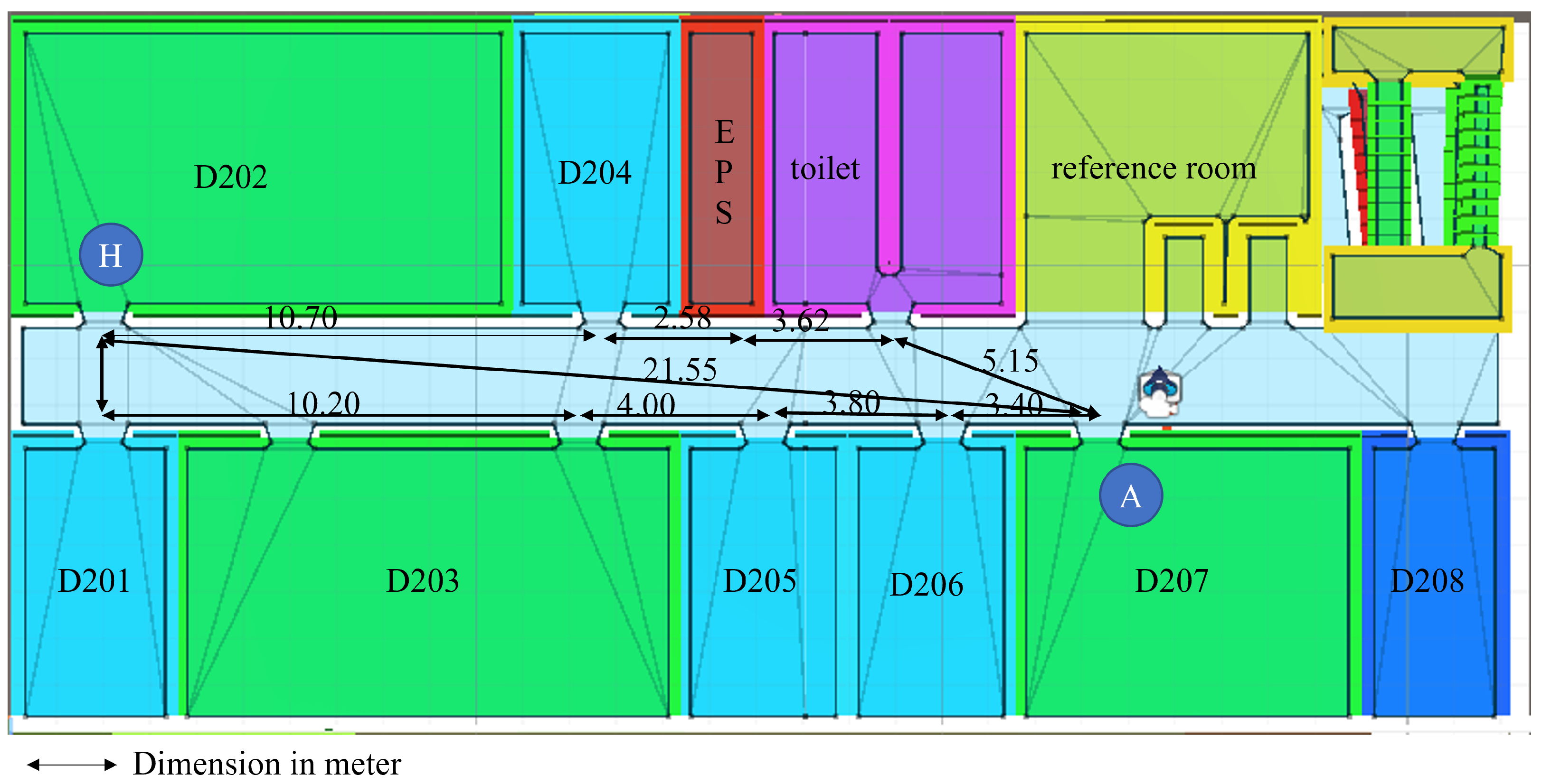
| Straight Distance to Room D202 | |||||||||
|---|---|---|---|---|---|---|---|---|---|
| Rooms | D207 | D206 | D205 | D203 | D201 | D202 | D204 | EPS | Toilet |
| h(n) | 21.55 | 20.50 | 16.70 | 12.70 | 2.50 | 0 | 10.70 | 13.28 | 16.90 |
| Component | Specification | |||
|---|---|---|---|---|
| PENS Graduate Building | #2 Engineering Building | |||
| Device | Samsung S22 | Samsung S9+ | Samsung S22 Ultra | Realme 9 Pro+ |
| OS | Android | Android | Android | Android |
| Chipset | Snapdragon 8 Gen 1 | Exynos 9810 | Snapdragon 8 Gen 1 | Mediatek Dimensity 920 |
| GPU | Adreno 730 | Mali-G72 MP18 | Adreno 730 | Mali-G68 |
| RAM | 8 GB | 6 GB | 12 GB | 8 GB |
| LCD | 2340 × 1080 pixels | 2960 × 1440 pixels | 1440 × 3088 pixels | 2400 × 1080 |
| Refresh Rate | 120 Hz | 60 Hz | 120 Hz | 90 Hz |
| Scenario (Angle) | PENS Graduate Building | #2 Engineering Building | ||
|---|---|---|---|---|
| Samsung S22 | Samsung S9+ | Samsung S22 Ultra | Realme 9 Pro+ | |
| 82.8% | 74.2% | 88.5% | 77.1% | |
| 88.5% | 77.1% | 91.4% | 82.8% | |
| 91.4% | 82.8% | 94.2% | 88.5% | |
| 100% | 94.2% | 100% | 91.4% | |
| 100% | 100% | 100% | 100% | |
| Success Rate | with Disturbance | without Disturbance | |||||||||||
|---|---|---|---|---|---|---|---|---|---|---|---|---|---|
| Angles | |||||||||||||
| PENS Graduate Building | 9F | 57% | 64% | 79% | 92% | 100% | 100% | 79% | 86% | 86% | 92% | 100% | 100% |
| 10F | 57% | 71% | 79% | 86% | 100% | 100% | 71% | 79% | 86% | 100% | 100% | 100% | |
| #2 Engineering Building | 1F | 57% | 64% | 79% | 86% | 100% | 100% | 79% | 86% | 86% | 100% | 100% | 100% |
| 2F | 57% | 64% | 79% | 86% | 100% | 100% | 71% | 79% | 79% | 100% | 100% | 100% | |
| 3F | 50% | 57% | 71% | 86% | 100% | 100% | 71% | 71% | 79% | 86% | 100% | 100% | |
| 4F | 57% | 64% | 71% | 79% | 100% | 100% | 71% | 79% | 79% | 92% | 100% | 100% | |
| Average | 55.8% | 64% | 76.3% | 85.8% | 100% | 100% | 73.6% | 80% | 82.5% | 95% | 100% | 100% | |
| Questions | PENS Graduate Building | #2 Engineering Building | ||
|---|---|---|---|---|
| Number of Students Use This System | ||||
| Agree | Disagree | Agree | Disagree | |
| This system is accurate | 30 | 0 | 20 | 0 |
| This system is useful | 22 | 8 | 18 | 2 |
| Want to use more | 23 | 7 | 15 | 5 |
| This system easy to use | 26 | 4 | 17 | 3 |
| Improve systems | 28 | 2 | 20 | 0 |
Disclaimer/Publisher’s Note: The statements, opinions and data contained in all publications are solely those of the individual author(s) and contributor(s) and not of MDPI and/or the editor(s). MDPI and/or the editor(s) disclaim responsibility for any injury to people or property resulting from any ideas, methods, instructions or products referred to in the content. |
© 2023 by the authors. Licensee MDPI, Basel, Switzerland. This article is an open access article distributed under the terms and conditions of the Creative Commons Attribution (CC BY) license (https://creativecommons.org/licenses/by/4.0/).
Share and Cite
Fajrianti, E.D.; Funabiki, N.; Sukaridhoto, S.; Panduman, Y.Y.F.; Dezheng, K.; Shihao, F.; Surya Pradhana, A.A. INSUS: Indoor Navigation System Using Unity and Smartphone for User Ambulation Assistance. Information 2023, 14, 359. https://doi.org/10.3390/info14070359
Fajrianti ED, Funabiki N, Sukaridhoto S, Panduman YYF, Dezheng K, Shihao F, Surya Pradhana AA. INSUS: Indoor Navigation System Using Unity and Smartphone for User Ambulation Assistance. Information. 2023; 14(7):359. https://doi.org/10.3390/info14070359
Chicago/Turabian StyleFajrianti, Evianita Dewi, Nobuo Funabiki, Sritrusta Sukaridhoto, Yohanes Yohanie Fridelin Panduman, Kong Dezheng, Fang Shihao, and Anak Agung Surya Pradhana. 2023. "INSUS: Indoor Navigation System Using Unity and Smartphone for User Ambulation Assistance" Information 14, no. 7: 359. https://doi.org/10.3390/info14070359