Article

Towards a Model-Based Multi-Layered Approach to Describe Traffic Scenarios on a Technical Level

Group System Analysis and Optimization, Department of Computing Science, Carl von Ossietzky University of Oldenburg, Ammerländer Heerstraße 114-118, 26129 Oldenburg, Germany
*
Author to whom correspondence should be addressed.
J. Mar. Sci. Eng. 2021, 9(6), 673; https://doi.org/10.3390/jmse9060673
Submission received: 25 May 2021 / Revised: 11 June 2021 / Accepted: 17 June 2021 / Published: 19 June 2021
(This article belongs to the Special Issue Engineering Safety Critical Maritime Systems)

Abstract

:
Highly automated vehicles are increasingly gaining the public’s attention. To achieve broad acceptance for the deployment of such vehicles, it is necessary to ensure their functionality and safety. One approach that has become popular in research is the scenario-based approach. However, manual testing of such complex systems is impractical and time-consuming. Using simulations to run and evaluate such scenarios appears to be the most viable approach. This, in turn, raises new challenges, especially in modeling the scenarios to be tested simulatively and incorporating the system under test as part of these. Since existing solutions do not solve these challenges satisfactorily—due to the strict separation of scenario and simulation model, among other reasons—this work addresses the need for a standardized, holistic, and extensible approach for modeling traffic scenarios to be executed simulatively. Requirements for such an approach are identified with focus on its application in simulation- and scenario-based verification and validation. Based on these, a model-based multi-layered approach is proposed. The foundations of this are then implemented utilizing a Meta Object Facility based heavyweight extension of the Unified Modeling Language metamodel. The resulting metamodel is used to demonstrate the applicability of the proposed approach by modeling a maritime traffic scenario.

1. Introduction

The research and development of highly automated and autonomous vehicles has made more progress in recent years than ever before. In this context, the automotive domain has a prominent position. However, due to its leading role in the worldwide transportation of goods and the resulting importance for the global and local markets and economies (see [1,2]), the maritime sector also moved into the focus of interest.
One of the biggest challenges in developing such traffic systems is their validation and verification (V&V). Especially for the successful introduction of future vessels with a degree of autonomy of three or higher, as categorized by the International Maritime Organization (IMO) [3], the proof of their safety is very important, since it is primarily through this that public acceptance of highly automated traffic systems can be achieved, as a study of the German and US print media has shown [4]. The corresponding degree of autonomy in terms of the automotive domain is SAE Level 3 and higher [5], for which new quality standards and test methods have already been developed and proposed, within the German research project PEGASUS [6], among others.
The introduction of non-deterministic approaches, such as the use of self-learning artificial intelligence, has led to the fact that classical procedures for safety verification such as model checking and theorem proving are no longer suitable. Instead, the behavior of these systems can only be checked at runtime. Additionally, the dramatically increased complexity and interconnectivity of such systems are resulting in blurred system boundaries and functional tests of a single isolated assistance system not being sufficient anymore [7]. Instead, the entire vehicle has to be considered as a system-of-systems [8,9]. Unfortunately, it is impossible to manually test all conceivable situations an automated or semi-autonomous vehicle could be exposed to in the future. Covering all permutations of environmental variables by real-world test drives requires an unreasonable amount of time and resources [10]. To tackle this issue, new methods for the release of highly automated transportation systems are currently under development. Most of these methods rely on the use of simulations due to their qualities of being able to be used during development, to be executed faster than real-time, to not expose people and equipment to any risk, etc.
To obtain significant results from simulative tests efficiently, a systematic approach is needed [11]. One approach that fulfills this need is the so-called scenario-based approach, as proposed by [6,7,12] and others. The approach is to identify, model, simulate, and evaluate traffic scenarios that are relevant for the significance of simulation results with respect to a specific traffic system under test (SuT). Because of its success in the automotive domain, it is assumed that this approach is also of great use for scenario-based simulative V&V of assistance systems in the maritime domain and other transportation domains such as rail, aviation, and aerospace. A general view on the main activities of such a simulation- and scenario-based approach and their interrelationships is shown in Figure 1.
The core of the simulative scenario-based approach is, as the name already suggests, the usage of scenarios as the foundation for the simulation runs. A few different definitions of what exactly constitutes a scenario exist in the literature. However, they are often similar in their essence. For the use in the context of simulation and testing, and the functional description of driver assistance systems, Ulbrich et al. [14] highlighted some of the existing definitions, used them as a foundation for the proposal of the three terms Scene, Scenario, and Situation, and gave a precise definition for each term. The concepts behind the terms differ mainly temporally and by information selection. A scene describes all information about the environment, including the scenery, dynamic elements, all actors, and their relationships among each other at a fixed point in time. Thus, in terms of time-based traffic simulations, one would obtain a unique scene for each point in time by taking a snapshot of all the information available in the simulation model at that time. A situation, then, is a further selection of the information contained in one of these scenes. More precisely, a situation contains only that information that is relevant in terms of decision-making for a single considered actor at the respective point in time and is therefore representing an element’s subjective point of view of the simulation model. A scenario, in turn, builds upon a starting scene and extends it by a temporal development in the form of actions and events, as well as the goals and values of the actors. Unlike a scene, a scenario thus refers to a period of time. Figure 2 shows the above-mentioned relationships once again in a graphical way. What can be clearly seen is the close link between certain points in time and the mentioned concepts. Therefore, the presented interpretation of a scenario is only applicable to discrete-time-based simulations.
To create meaningful scenarios, these can, on the one hand, be derived from historical traffic data by identifying critical situations such as near-collisions [11] or applying even further processing methods [15], and on the other hand, be generated from scratch using self-learning generating methods [16]. Manually creating them based on expert knowledge is another method, albeit usually a much less efficient one. Common to all approaches is the need for a possibility to persistently define the identified scenarios. Especially with regard to the desired simulative execution of those scenarios, this point greatly gains in importance. In the context of this work, the term scenario model is used when referring to a persistent technical representation of a scenario. A scenario model must therefore be ready to be used as input by a simulation system and to be transferred into a corresponding simulation model to serve as the needed structure for the simulation’s execution itself and its ground truth.
In order to achieve the overall goal of rolling out (highly)automated and fully autonomous transport systems in the near future, significant work has already been carried out recently to develop and implement most of the activities of the simulative scenario-based V&V process (cf. Figure 1). Especially possible methods and approaches for the definition of automation risks and the new requirements resulting from these, the systematic identification and definition of meaningful (logical) scenarios, and the evaluation of test runs using risk analyses based on metrics and criteria derived from requirements have received a lot of attention lately. However, the unified modeling with special attention to the transition from scenario to a discrete time-based simulation was often not considered closely enough. This is especially true for the maritime domain and has led to a very heterogeneous solution landscape in terms of technical modeling of scenarios for their simulative execution as the core of scenario-based V&V of transport systems. The aim of this work is therefore to close this gap by developing an approach for modeling traffic scenarios that meets the critical requirements for such an approach as a basis for simulation- and scenario-based V&V to be able to assure the functional safety of highly automated and autonomous traffic systems.

2. Method

In order to accomplish the aim of this work outlined above, in the following, the critical requirements for such a scenario model are identified and a novel model-based multi-layered approach based on these is proposed. Before that, the need for a new approach is highlighted by a brief comparison of the identified requirements with the most important existing contributions in the scientific community. In order to demonstrate the basic applicability of the developed approach, a simple traffic scenario from the maritime sector, consisting of a single moving ship and a stationary lighthouse, is finally modeled and explained. For this purpose, the essential core of the concept is first implemented as a heavyweight extension of the Unified Modeling Language (UML) and this resulting meta-model is then applied. To conclude, the findings are briefly reviewed and it is discussed whether the objectives set have been achieved. For a better overview of the structure of the present work, the individual chapters and the flow of results, as well as interdependencies, are shown graphically in Figure 3 below.

3. Requirements for the Modeling of Traffic Scenarios

The following takes a closer look at the ideal process for simulatively ensuring the safety of (highly) automated and autonomous traffic systems. Particular emphasis is placed on the importance of integrating sequential continuous testing as part of system development and the use of the V-model (Section 3.1). It then quickly becomes clear that the individual development and test phases also imply different requirements. This is given by the corresponding maturity level of the system at the respective stage (model, software, hardware) and the resulting test integration types. In the initial phases of system development, only a model exists, which should already be able to be tested simulatively through Model-in-the-Loop (MiL) tests. In the further course of system development, Software-in-the-Loop (SiL) and Hardware-in-the-Loop (HiL) test runs become necessary. Finally, in Vehicle-in-the-Loop (ViL) tests, the corresponding system is integrated into a vehicle that is integrated holistically into a simulated environment in order to test it as a whole for functional safety. For each development and test phase, the possibility of integrating the system to be tested must be given (Section 3.2). Analogous to the possible different characteristics of the system to be tested, it may also be necessary to consider the simulated road users at different levels of abstraction, each appropriate to the current use case (Section 3.3). Subsequently, the relationships between a scenario model, the actual simulation and its internal data model are considered, as well as the integration of the system under test. This also results in important requirements for the modeling of scenarios as a basis for simulation runs within the framework of the V&V processes described in advance (Section 3.4 and Section 3.5). Finally, the identified requirements are summarized in a compact way and serve as a basis for the development of the novel concept as well as for the verification of the fulfilment of the objectives in the further course of the present work.

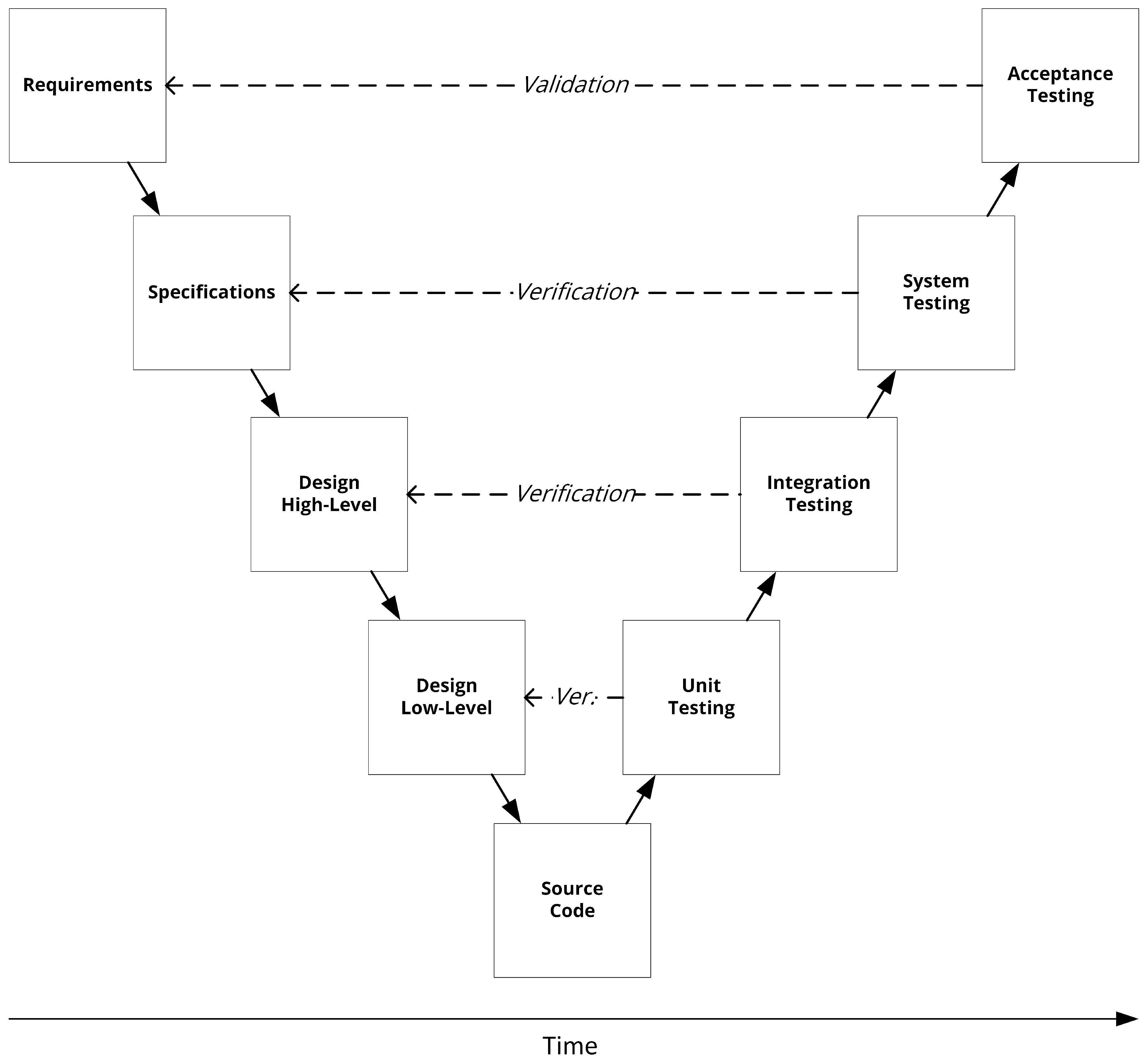
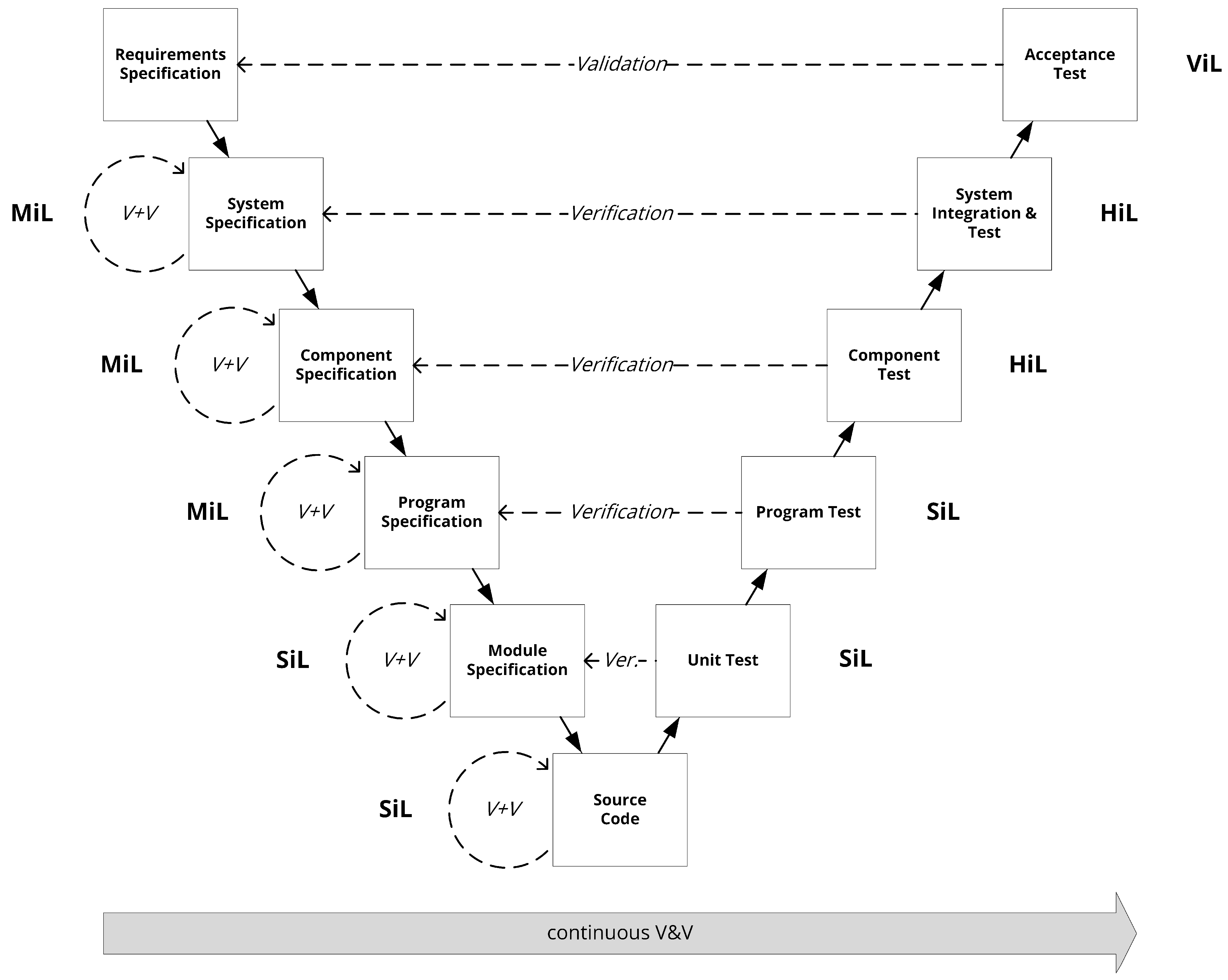
3.1. Continuous V&V in Transportation Systems Engineering

When developing highly automated and autonomous traffic systems, it must be taken into account that these systems can potentially cause damage to people, materials, or the environment. For this reason, there are some established standards whose aim is to avoid incalculable risks that could result from the malfunctions of the developed system. One of these established standards in the automotive sector is ISO 26262 [17], which revolves around the key concept of functional safety. Functional safety is part of the overall safety of a system, focuses on the functionality of a system, and ensures that the system functions correctly in response to its environmental conditions at any time. As a systematic way to ensure functional safety, ISO 26262 proposes a development process model based on the well-known V-model as it is shown in Figure 4. One standard targeted at the development of electronic systems for maritime traffic systems is ISO 17894 [8], which suggests a similar process model based on the V-model in one of its annexes.
The traditional V-model, which is well established in systems engineering, describes a procedure that supports the development process in accordance with ISO 15288 [19] and therefore provides well-structured support for systems engineering. In general, the traditional V-model is divided into two successive phases. First, the process passes through the creation phase (left side) and then the verification and validation phase (right side). At each step downwards, the system is divided into smaller parts and these parts are then worked on in parallel. At the beginning of each creation step, requirements for the respective resulting artifacts are identified and documented. These are then used later in the verification and validation phase to successively check the artifacts created earlier for their fulfillment and thus prove their correctness. This two-part and strictly separated process of creation and examination is no longer suitable for the development of modern, interacting, non-deterministic, and highly complex systems such as automated and autonomous traffic systems (cf. [20]). This is due to the fact that V&V activities are integrated only late and not sufficiently into the traditional overall development process in the context of the V-model [21].
Based on the idea of a phased deployment proposed in [20], precisely specified subsystems and models should therefore be identified and tested during the creation phase. A very similar approach has already been presented by Brinkmann in [21] by the name of front-loading of the V&V. These small simulation-based in-process V&V loops can be seen in Figure 5. Instead of continuously going through all creation steps, the respective artifact of a single step is verified and validated by the use of simulation before moving on to the next step. If problems become apparent here, this is fed back into the very same step as input and appropriate adjustments are made. This continuous V&V throughout the entire lifecycle makes it possible to detect errors as early as possible and subsequently eliminate them at a low cost. In addition, clearly defined subsets of the overall requirements tailored to the responsibilities of individual subsystems can be checked this way. This, in turn, reduces the overall V&V complexity of a complex system of systems, in the manner that modern transportation systems tend to be.

3.2. Interoperability

In addition, models of varying complexity of the traffic system under consideration are required for the different phases in the development of a driving assistance system. For example, Hanke [13] has already identified three levels of granularity for the automotive domain, analogous to the simplest variation of the traditional V-model of software development: World Level or System Level, Car Level or Subsystem Level, and Processing Level or Component Level. In the first case, the entire vehicle is viewed as a model and thus a single abstract behavioral function can be sufficient as a holistic abstraction. On the second level, however, the individual subsystems within the traffic system as well as their interactions have to be modeled and simulated. At the most detailed level, each individual component of a subsystem is considered. To be able to cover also the smallest parts of a common software development process, additionally, a fourth level is introduced, which considers single functional units within a component.
Since the extended V-model shown in Figure 5 is more detailed than the traditional one due to the nature of transport systems being systems-of-systems, it has more fine-grained individual steps. With regard to the use of automated simulative tests, these can then, in turn, be grouped into four test categories in terms of the type of system-under-test: Model-in-the-Loop (MiL), Software-in-the-Loop (SiL), Hardware-in-the-Loop (HiL), and Vehicle-in-the-Loop (ViL) [22,23]. Those categories then can again be divided into the four levels mentioned above, resulting in the nine possible types of integrating the SuT in a simulation run in the V&V environment shown in Table 1. Each of these integration options brings its own requirements regarding the connection to the rest of the simulation system. This set of requirements can be summarized under the term of interoperability. In this context, interoperability means, in addition to the traditional sense of communication and cooperation between the simulated (sub-) systems, the possibility of seamlessly integrating any SuT during all lifecycle phases of the transport system in development.
Table 1. Levels of system view and the type of SuT integration that is possible at each of these.
MiLSiLHiLViL
System LevelX X
Subsystem LevelXXX
Component LevelXXX
Program-Unit Level X

3.3. Varying Abstraction Levels of Simulated Traffic Participants

Depending on how far the development of a traffic system has progressed on the horizontal time axis (cf. Figure 5), different requirements are imposed on the scenarios to be tested. Whereas a very abstract simulation may suffice for the simulative MiL test in the system specification step—e.g., traffic participants represented by simple points on an empty two-dimensional plane—a simulative ViL acceptance test at the final step must represent the real world as accurately as possible. Both of these extreme cases, as well as all cases in between, must consequently be supported or at least made possible by the scenario model.
Because the simulations studied here, in contrast to macroscopic traffic simulations, have to observe each single traffic participant individually, it is obvious to realize the modeling and simulation in the sense of an agent-based system (cf. [24]). Russel and Norvig [25] (p. 34) describe an agent as “anything that can be viewed as perceiving its environment through sensors and acting upon that environment through actuators”. With this definition given, it is easy to see that every automated vehicle fulfills the criteria to be an agent naturally. Sensors such as LiDAR perceive the vehicle’s environment, electronic systems process this data, derive decisions upon it, and then the vehicular system influences itself and the environment through actuators by altering their speed, for example. In the context of a virtual environment of a simulation, the data are, of course, not generated by sensors but read from the shared environment of all agents. Thus, the terms sensor and actor can be replaced here by the well-known and more universal terms read and write, in the sense of an agent obtaining the values of interest from the shared environments simulation model. For the above-mentioned, maximally abstract edge case, a simulated traffic participating system can therefore be represented as a single monolithic agent, as shown in Figure 6.
The introduction already briefly addressed the fact that modern vehicles can no longer be considered as a single system, but rather constitute a so-called system-of-systems (SoS). Already the ISO 17894 standard indicates that a modern ship is more than a monolithic system: “The overall effect of the use of PES [programmable electronic systems] is that the ship becomes one total system of inter-linked PES and crew which work together to fulfill the operator’s business goals” [8] (p. 5). This is true even if the crew is not included. This is mainly due to the fact that the individual electronic system components can be managed by different manufacturers, be of varying ages, and may even have been developed in compliance with dissimilar standards. This is even more true when it comes to (highly) automated systems and subsystems, as these are usually developed individually, can in theory act in a standalone manner but rely on the input of other subsystems as part of their use within a vehicle, and their output may also be used by other systems. For example, one subsystem could pre-process sensor data, which in turn could then serve as input to another subsystem. A corresponding agent model can be seen in Figure 7.
In contrast, in [27] (p. 271), it is defined that only “[…] a system that has operational and managerial independence of its elements is a system-of-systems”, and for a long period of time individual PES of a vehicle, no matter how complex those themselves were internal, could not be described as functionally independent. However, with the increased use of non-deterministic processes such as artificial intelligence in these systems, they should be considered autonomous and independent, because they are self-contained and their output cannot always be determined by knowing the inputs. The managerial independence of the PES is, e.g., especially given in the maritime domain by heavily distributed and independent development, installation, update, and maintenance processes of the individual systems the vessel is comprised of. According to Annex G of ISO/IEC/IEEE 15288 and 12207, a system-of-systems brings together a set of systems for a task that none of the systems can accomplish on its own. While operating within the system-of-systems, each constituent system keeps its own management, goals, and resources [19,28]. This definition supports the proposition that modern vehicles must be considered as such.
In order to be able to test the safety of an interconnected system-of-systems like that in a simulated environment, it must be possible to model traffic participants, including their components and their interdependencies, as part of the scenario modeling. It must also be possible to exchange the individual interdependent system models easily.
Overlaps exist here with the previously identified requirement group of interoperability between the SuT and the modeled simulated systems. To enable the types of integration shown in Table 1 at the subsystem, component, and program unit levels, the fine-granular view of a simulation participating agent revealed in this section is necessary.

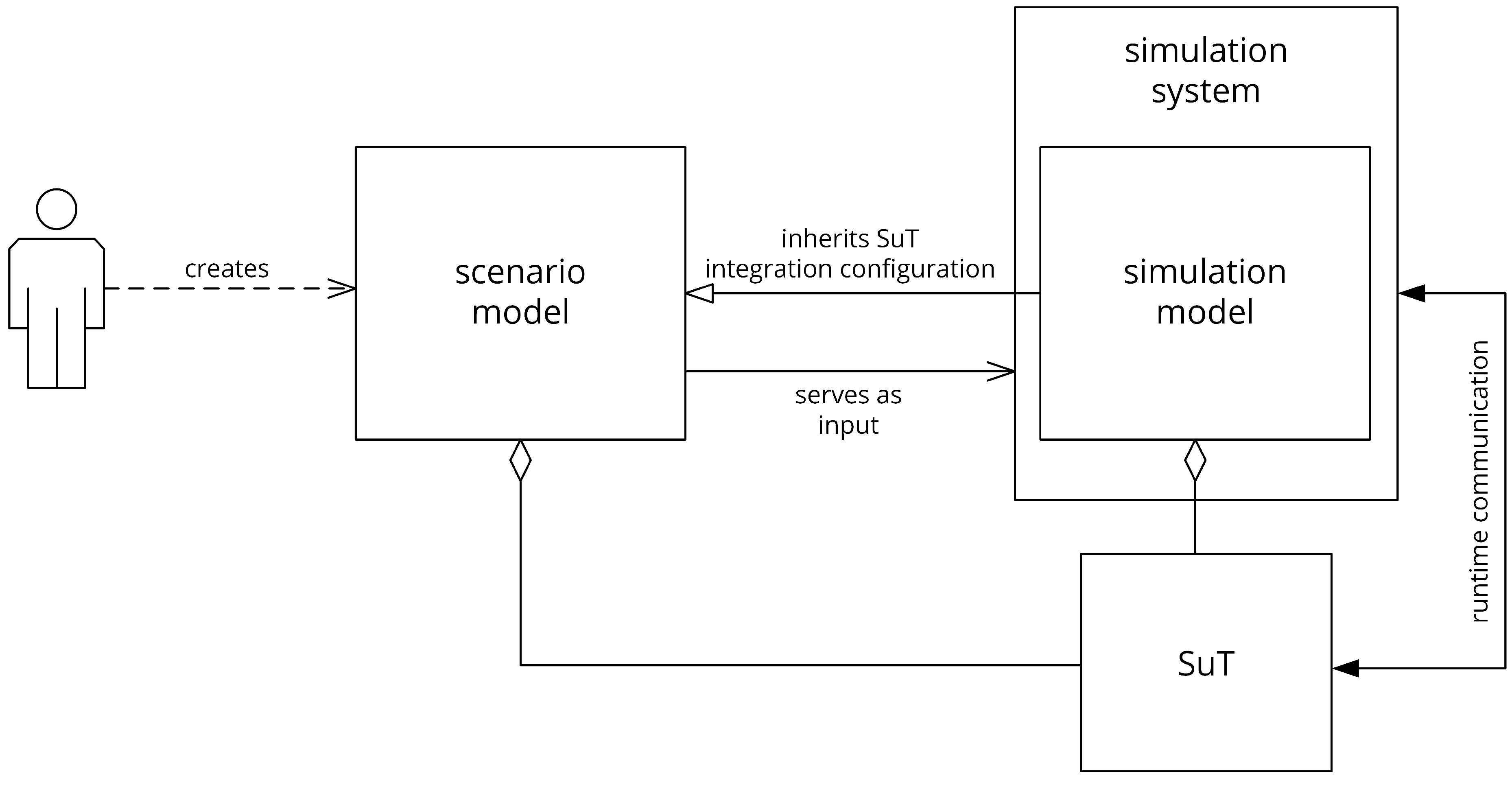
3.4. Early SuT Integration

In the previous subsections, the need to be able to integrate a SuT as either a whole traffic participant (MiL, Vil), a constitute system of a traffic participant (MiL, SiL, HiL), a component of a system (MiL, SiL, HiL) or a unit of a component (SiL) was identified. Because in most cases a SuT is not part of the software-based simulation system itself—and in the case of HiL and ViL, cannot be at all—one approach here is to connect to the external system through network communication at simulation runtime. To ensure that exactly the concepts contained in the scenario model are also the ones that are simulated, the mapping of the scenario model onto the simulation model must be bijective. Therefore, in order to guarantee that the scenario model correctly reflects the simulation model and vice versa, at least an appropriate placeholder must also be introduced at the early stage of scenario modeling. The SuT, respectively its connection configuration, is consequently an element of both models. The characterization of the SuT integration, including its technical configuration, as well as the functional associations with other model components, must therefore also be maintained in both models. This redundancy of information can then lead to inconsistencies between these models. If this, on the other hand, causes the simulation system to behave differently than it was intended when modeling the scenario, time-consuming troubleshooting may be the consequence.
To achieve complete scenario models that entirely represent the elements of the simulation to be executed later, and at the same time to avoid redundant configurations, it is desirable to undertake the manual SuT integration exclusively as part of the scenario model. The simulation model would then inherit this configuration. Based on the inherited configuration, the simulation system could then use some kind of communication at runtime to let the SuT participate in the scenario run accordingly (cf. Figure 8). Such an approach would additionally lead to the fact that users of such simulation setups only have to deal with scenario modeling and do not have to additionally realize the integration of the SuT into the simulation system, which can be a time-consuming process.

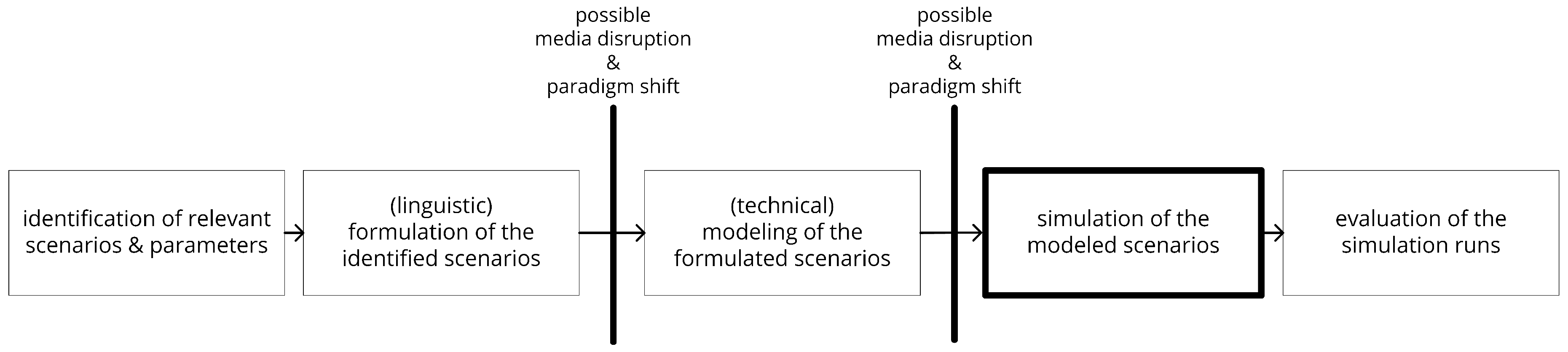
3.5. Holistic View on Scenario-Based Simulation

The typical scenario-based testing process generally includes at least three phases (cf. [11,12,13,29,30]): the identification of relevant scenarios, the modeling of the identified scenarios, and the subsequent simulative execution and evaluation of the modeled scenarios (cf. Figure 1). Those phases are often treated independently under the usage of different concepts, tools, file formats, experts, etc. Information resulting from these phases is then bound to a specific medium. For example, it could be formulated linguistically, persisted in a structured manner in the form of XML or similar standards, or exist as transitory object instances of an object-oriented programming language. If a transition to another medium is necessary before further processing of the information can take place, this indicates at least a media disruption, but often even a paradigm shift. Disruptions like these may occur between phases if different approaches, concepts, or formats are used in the individual phases, as can be seen in Figure 9. Transitioning from one format to another or from one paradigm to another can result in information loss or distortion if the direct mapping of modeled concepts and parameters is not possible.
To avoid this potential problem from the outset, it is desirable to introduce a holistic approach to scenario modeling across the entire process. This means that a scenario model should be able to be used beyond the technical modeling phase during the scenario identification and simulation phase. The latter could be achieved by an approach similar to the one mentioned earlier for SuT integration configuration inheritance, in that the simulation model inherits from the scenario model.

3.6. Requirements Summary

In summary, the elaborated requirements that must be fulfilled by a scenario model to support the presented simulation- and scenario-based V&V process optimally can be summarized as follows:
  • The scenario model should be built upon an extensible and customizable foundation so that it can be applied to the different needs of different transportation domains and across the entire V&V process.
  • The scenario model should create the possibility to integrate the SuT seamlessly as part of the scenario at the earliest stage possible without the need to adapt the configuration of the executing simulation system itself.
  • The scenario model should pursue a holistic approach reaching from the scenario modeling all the way to executing the simulation in order to reduce media disruptions and paradigm shifts within the simulative V&V process.

4. Related Work

Several contributions on the general topic of simulation- and scenario-based V&V of highly automated vehicles already exist. Therefore, it is important to briefly discuss them with regard to the requirements identified in the previous chapter for a scenario model optimally supporting the simulation- and scenario-based V&V process. The following list is by no means exhaustive and only a selection of the available approaches, tools, and formats has been considered. The selection criteria included, among others, the availability, topicality, and the current state. Thus, commercial and closed applications were excluded from closer consideration, as were outdated approaches or purely theoretical concepts without an adequate usable implementation. In addition, only work that is either domain-independent or targeted at the maritime domain was considered. Since the automotive domain can already refer to much more advanced results due to public attention, work from this domain is also considered. The following reflections are grouped by their scope and objective into the subsections "Simulation Systems" and "Scenario Description".

4.1. Simulation Systems

In the following, related work that provides a complete simulation system is examined. Since the configuration of the simulated entities, often in the manner of a scenario as it has been defined earlier, is also required to perform traffic simulations, it is worthwhile to consider these, as well.

4.1.1. Open Simulation Platform

The Open Simulation Platform (OSP) [31] is an open-source initiative founded by DNV GL, Kongsberg Maritime, NTNU, and SINTEF Ocean for distributed co-simulation of maritime systems and equipment. The goal of the project is to “enable collaborative digital twin simulations to solve challenges with designing, commissioning, operating and assuring complex, integrated systems” [31] (p. 240). The idea behind OSP is to extend the Functional Mock-up Interface (FMI) standard for reuse and simulative coupling of system models while protecting the respective developers’ intellectual property. It provides additional interfaces and specifications to make connecting models and sub-simulators binary and semantically easier. The OspModelDescription makes it easy to model the inputs, outputs, connections, and dependencies of the individual models [32]. The nature of the FMI standard, however, leads to the fact that properties and variables of the individual Functional Mock-up Units (FMU) are held by the units themselves. Thus, a coherent technical description of the scenario does not exist and is not the goal of OSP. That said, simulation runs can indeed be set up and influenced by loading a JSON file that contains timed events, which contain a variable and a value each. The given variable will then be set to the given value when the set point in simulation time is reached. However, this type of scenario description does not meet the identified requirements because the models, structural descriptions, and descriptions of progression over time are highly distributed and interdependent.

4.1.2. HAGGIS

The platform HAGGIS (formerly an acronym for Hybrid Architecture for Granular, Generic and Interoperable Simulations) is a modeling and co-simulation environment for building virtual e-Navigation testbeds and part of the eMaritime Integrated Reference Platform. Its goal is to enable rapid testing of new e-Navigation technologies in a simulation environment. HAGGIS consists of a set of modules such as a maritime traffic simulation (MTS), a sensor simulation, environment simulation, and human behavior models [33]. A scenario is created by the use of the contained World Editor that provides a system model to allow setting up a static scene. This system model contains the fundamental components of all used resources, actors, and environmental factors. Additionally, routes for vessel traffic can be modeled or imported. The use of HLA as communication middleware enables the integration of external sub-simulations supporting the same standard. To ensure interoperability a common semantic model based on common standards such as S100 forms the core of HAGGIS. A scenario can be roughly summarized as a world model that contains vessels as well as environmental factors and additional objects, such as buoys and other navigational marks [34]. The MTS can be configured to communicate with a SuT as part of a simulation run. While this enables the simulative V&V of models (MiL), software (HiL), and hardware (HiL), in many cases it is not especially easy to implement this integration and must be executed on the simulation and scenario side. The model-based approach to implementing the underlying data model leads, in principle, to very good extensibility and adaptability. However, the tight embeddedness in the core of the simulation platform leads to dependencies and therefore to adjustments that have to be made to the simulation system and its components, and to the fact that scenarios for different degrees of abstraction are not easily realizable.

4.1.3. CARLA Open Urban Driving Simulator

Car Learning to Act (CARLA) [35] is an automotive driving simulation system implemented as an open-source layer on top of the real-time 3D creation platform Unreal Engine 4. It aims at supporting training, prototyping, and validation of autonomous driving models in urban traffic environments. Urban environments and 3D models of static and dynamic objects such as vehicles, buildings, and pedestrians are included for free. The reason for the development was that existing solutions were either not detailed enough or did not support detailed benchmarking of driving policies to effectively support the development of driving models. To achieve this, CARLA supports a flexible setup of sensor suites and a simple python API. Client scripts written using this API are then able to create an actor, attach sensors to it, and then retrieve the sensor data, process it, and calculate the parameters needed by the controller. The calculated values are then sent back to the CARLA simulator [36]. Thus, a dedicated scenario model does not exist, since the design of the content is fixed in the simulation system and can only be influenced through the API in a controlling way. Simple integration of external systems beyond Driving Functions is also not possible due to the limited control commands.

4.1.4. LG Silicon Valley Lab Simulator

The LG Silicon Valley Lab Simulator (LGSVL Simulator) [37] is a high-fidelity simulator for autonomous driving. Its core engine is developed using the Unity Game Engine. The project is open source with the source code being freely available. Furthermore, it provides the possibility to generate synthetic data for usage in machine learning and to test Vehicle-to-Everything (V2X) systems. The simulator provides a communication bridge that enables a connection between the simulator and an Autonomous Driving stack. A system that is not an autonomous driving stack, such as an alarming system, can therefore not be connected easily without further effort.
The simulation itself can be broken down into environment simulation, sensor simulation, vehicle dynamics simulation, and control simulation of a vehicle. Test scenarios consist of an environment to simulate in which an external autonomous driving stack can be placed to verify its behavior. Variables such as time of day, weather, road condition, as well as distribution and movement of moving agents can be influenced through a Python API. To create scenarios, a script, therefore, must be written, which sets up the environment and the simulation parameters as intended. A dedicated scenario model does not exist, which, while eliminating a potential media break, creates a rigid dependency of the scenario on the simulation models.

4.2. Scenario Description

The formats and languages considered below are focused on the modeling of traffic scenarios and therefore directly relate to the essence of this work. A comparison with the specified requirements is therefore unavoidable. Other approaches exist, such as the recently opened Open M-SDL [38], which are explicitly focused on the modeling of road traffic scenarios but leave the technical integration of the SuT mostly to the simulation system/model. Therefore, not all of them are explicitly listed here.

4.2.1. ASAM OpenDRIVE®, OpenCRG®, OpenSCENARIO®

OpenSCENARIO defines a data model and a derived file format for describing the dynamic content of driving and traffic simulators. The standard enables the description of vehicle maneuvers in so-called storyboards, which are divided into stories, acts, and sequences. Other content, such as pedestrians, traffic, and environmental conditions, is included in the standard, as well. The data for maneuver descriptions in ASAM OpenSCENARIO are organized in a hierarchical structure and serialized in an XML file format. The corresponding schema is provided with the standard [39]. The standards are developed with the use of the Unified Modeling Language (UML) and then transformed into the representing XML schema. This creates the possibility to extend the usable contents. The standard can be used together with road network descriptions from OpenDRIVE and road surface profiles from ASAM OpenCRG. The three standards complement each other and together they cover the static and dynamic contents of an automotive driving scenario [40]. In summary, it can be said that these standards facilitate the exchange of data between creation tools and simulators, and the use of the data as input for different simulators from different vendors. Many major vendors and manufacturers already use one or more of the standards mentioned, and many automotive driving simulators provide support for the formats. However, because the standards are entirely targeted at the automotive domain, allow only limited support for the integration of different SuT types during scenario modeling, and lead to a strict separation between scenario and simulation model, OpenSCENARIO does not meet the requirements established earlier.

4.2.2. Traffic Sequence Charts

Traffic Sequence Charts (TSC) [41] are a declarative specification language designed to be intuitively understandable through the visualization of scenarios. They are based on formal semantics [42] and aim to support the testing of a developed driving system by specifying a scenario catalog that contains the test cases in which the vehicle under test is examined to show the expected behavior. A TSC specification consists of a formal world model that defines the entities that can be used, a visual specification of scenarios and/or rules and restrictions, and a symbol dictionary that defines the connection between the visual symbols and the entities of the world model. TSCs handle entities defined in an ontology of all types of artifacts that need to be observable in real traffic situations. In contrast to the previously mentioned scenario languages, TSCs do not aim at defining a single traffic evolution, but rather at specifying scenario bundles, visualizing the constraints defining the scenario bundle. Therefore, due to its declarative nature, a TSC scenario usually represents an infinite number of concrete traffic evolutions. [41]. Due to their visual and descriptive nature, their primary goal is not to serve as direct input to a simulation system. Furthermore, the possible behavior of road users is based on formal rules and constraints instead of functional evolution over simulative time steps. A technically oriented connection of the SuT during scenario modeling—one of the key points of the identified requirements—is not intended.

4.2.3. SCENIC

SCENIC [43] is a domain-specific probabilistic programming language for scenarios that are distributions over scenes. This is realized by utilizing probability distributions over configurations of physical objects and agents. The main goal in doing so is to generate meaningful synthetic data sets that are useful for deep learning tasks. Although it was initially developed for an automotive use case, the possibility of using it in other domains has already been demonstrated: SCENIC has been successfully interfaced to X-Plane flight simulator in order to test Machine Learning-based aircraft navigation systems. However, while doing so, the possible elements of the scenario are always limited by the particular target simulation. Therefore, the holistic approach aimed at here is not achieved. In addition, strictly speaking, only scenes are generated in reference to the previously mentioned definition. Therefore, although SCENIC implements a very exciting approach to generate a large number of synthetic traffic situations in a short time, it is not suitable for the usage envisioned.

5. Model-Based Multi-Layered Approach

In the following, the novel approach of a model-based multi-layered scenario description is presented and the ideas and concepts involved are shown, justified, and briefly explained step by step. Addressing the various challenges individually and bringing them together in a homogeneous comprehensive approach ensures that the previously defined requirements can be met with the proposed approach.

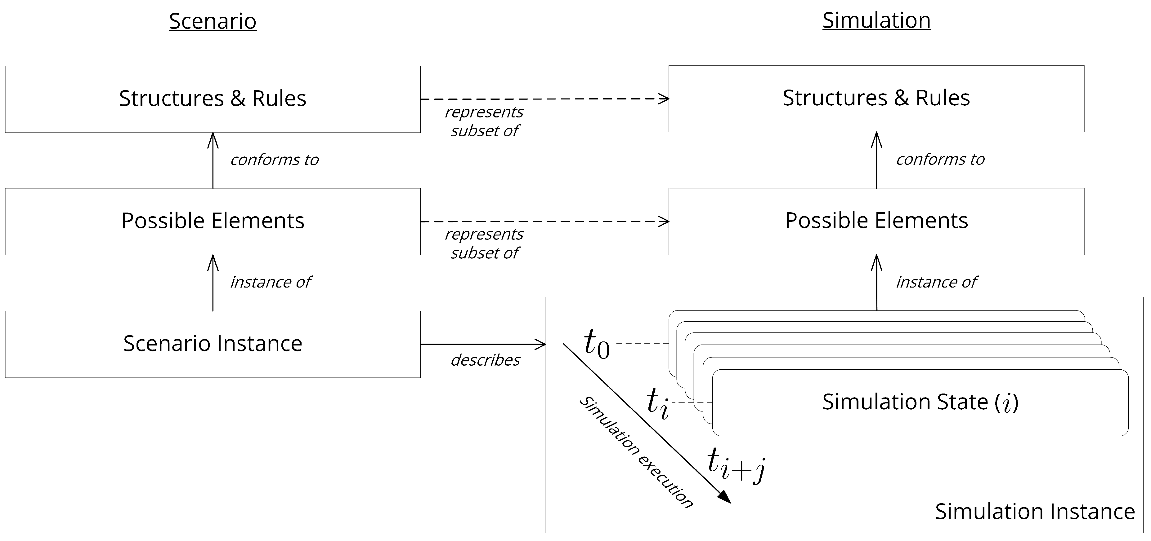
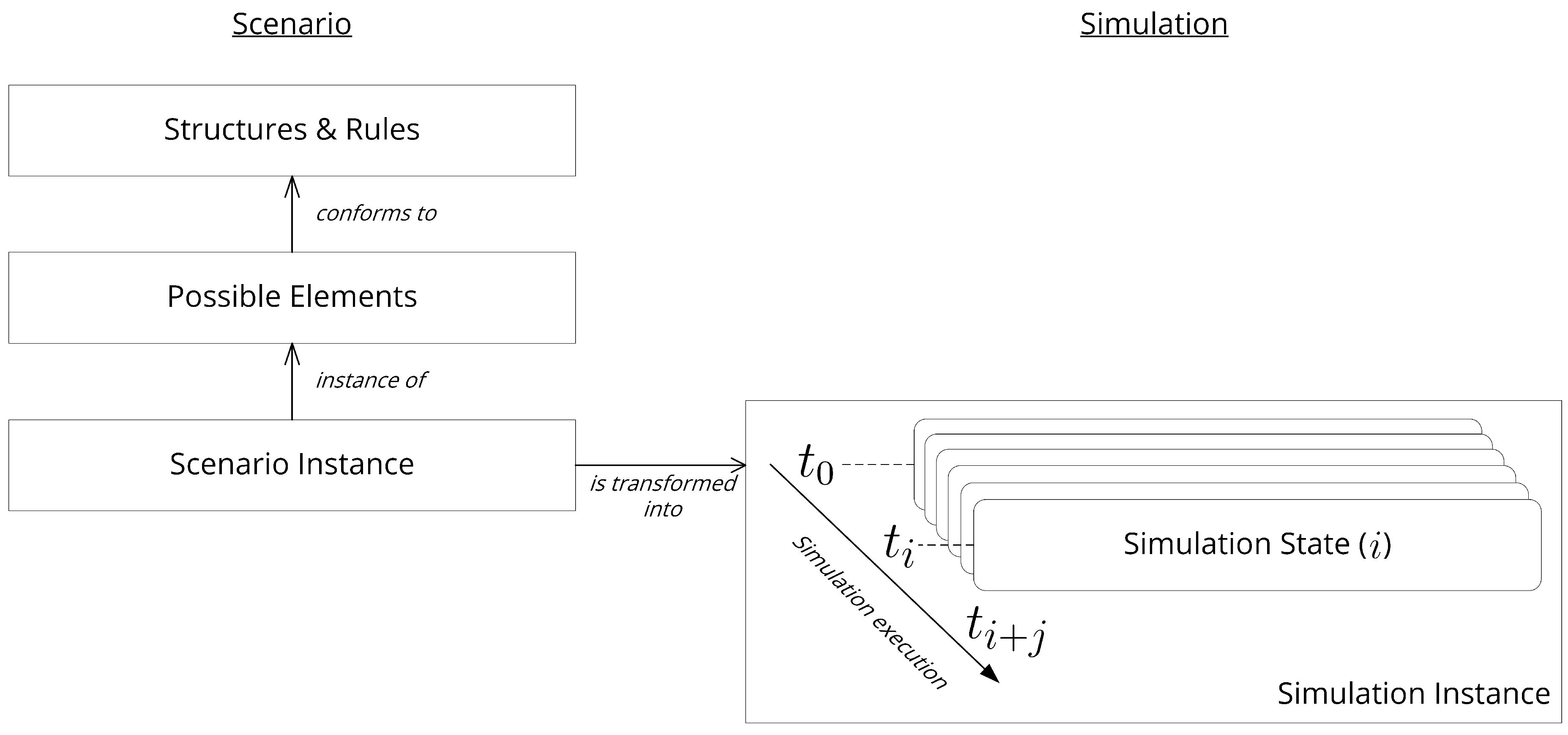
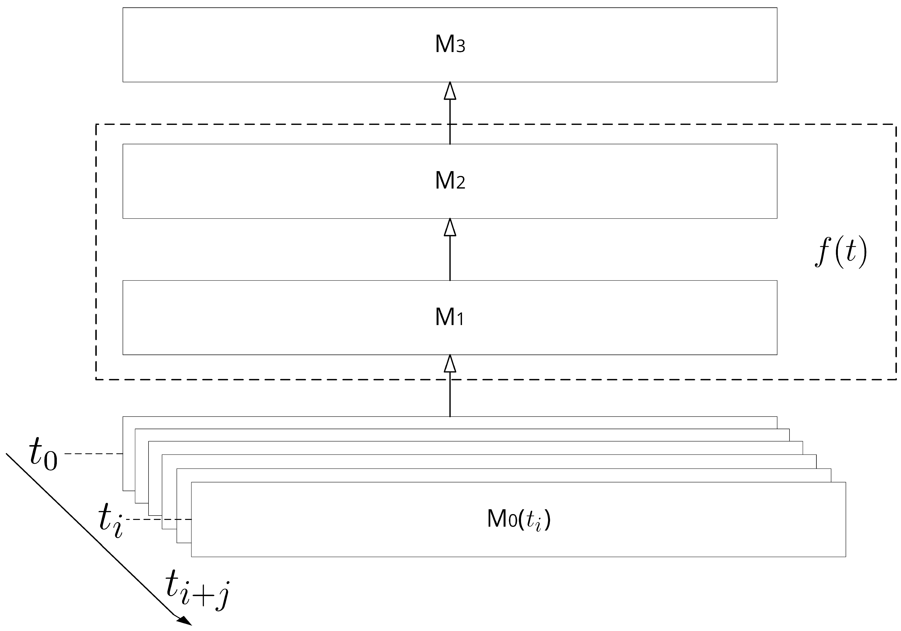
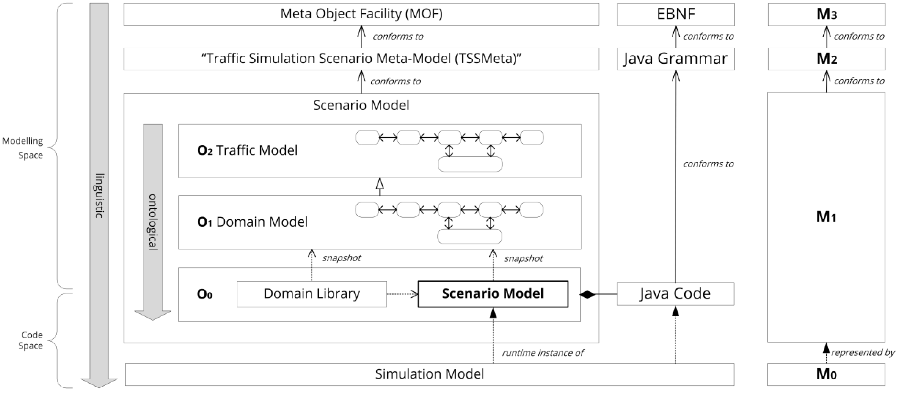
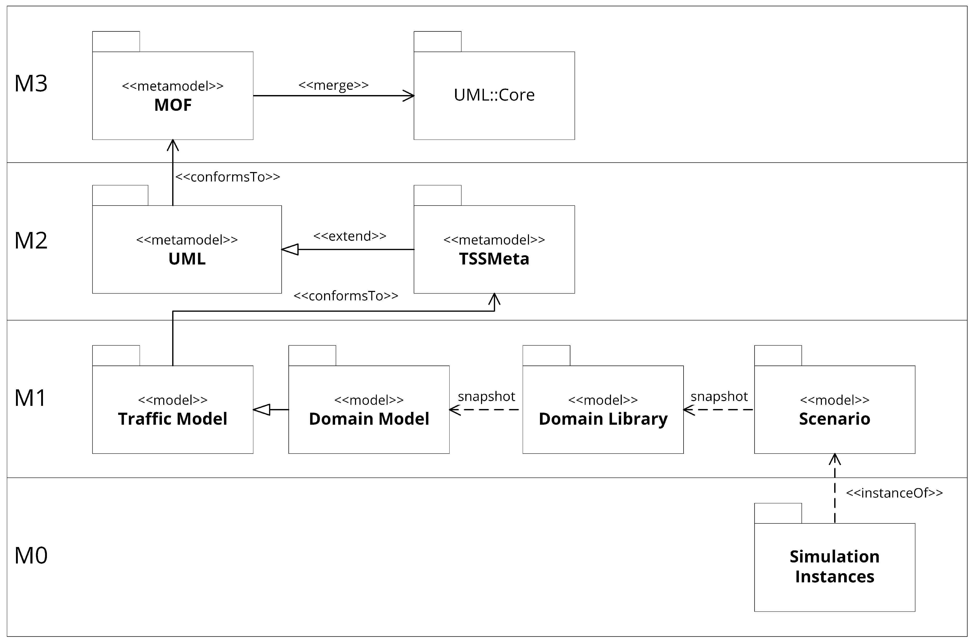
5.1. Model-Driven Simulation

Taking a closer look at the conventional approach using separate scenario and simulation models and formats, as depicted in Figure 10, the building blocks of those can be identified. The left side of the figure shows the structural composition of a scenario and the right side that of a simulation system respectively the contents of a specific simulation run. Roughly speaking, the technical representation of a scenario is composed of a subset of the set of available elements. In the maritime context, the set of available elements could include different types of vessels, buoys, lighthouses, water features, etc. However, the concrete scenario instance for testing a collision-avoidance system could then only consist of two vessels of the type “tanker”, which are on a collision course. Of course, the available elements are not implemented randomly, but rather conform to a common base of prescribed structures and rules. This could, for example, already be partly determined by the language or format that is being used to describe those elements. An analogous structure can be identified on the right side—the simulation side. Again, given rules and structural constraints serve as the basis for defining a set of elements that can be part of a simulation run. In the end, however, only a subset of the possible elements takes part in a concrete simulation instance.
In order for a scenario to be a valid description of a simulation instance or rather its initial state, the contents of the layers on the left-hand side must represent a subset of the contents of the layers on the right-hand side as accurately as possible. If the scenario contains elements or structures that the simulation does not have knowledge of, this scenario cannot be completely mapped in the simulation. This, in turn, will lead to a loss of information when transferring the scenario contents into the simulation. On the other hand, this also leads to the possible loss of potential of the simulation system through functionalities and structures on the scenario side that do not (or cannot) represent the simulation systems elements functionalities in their entirety. This case would occur, for example, when the simulation is able to represent that vessels can have an initial speed right at the start of the simulation, but the scenario element “vessel” does not provide a parameter for the initial speed.
One possibility to eliminate this multi-layered dependency is to join the left and right sides from Figure 10, which would lead to the structure shown in Figure 11. This would also contribute to the fulfillment of requirement 3 formulated at the end of Section 3.
The proposed approach to remove the dependencies now leads, in turn, to the question of how a relatively static and primarily structurally oriented description of a scenario can be transformed into a dynamic and time-based simulation instance. One approach designed to address this particular challenge is the Model Driven Architecture (MDA) approach formulated by the Object Management Group (OMG) [44]. Although the main application area of MDA is the implementation of business processes, it can be used with great results in many other domains and areas. The MDA enforces the basic idea of letting models become artifacts of software development, which are specified by open standards in a formal way so that an automated implementation of the software system is possible by model transformations. For this purpose, the syntax and semantics of these models must be unambiguously evaluable and machine-readable. The theoretical outline for the definition of such models is provided by the concept of metamodeling.
A metamodel is a model of a model, and therefore describes the possible elements that can be used to create the model. This definition is also quite fitting for the layered structure identified in Figure 10 and Figure 11: every layer holds the elements and concepts that are used to describe the elements and structures of the following layer. Meta Object Facility (MOF) [45] is a standard language for creating such meta-models. It is a subset of the Unified Modeling Language (UML) [46]. More precisely, UML and MOF share a common core, which in turn is part of the UML standard.
Being a framework used for defining specific modeling languages, the MOF specification introduces a four-layer metamodeling architecture [45,47]:
M3: The meta-metamodel
M2: Metamodels (for example, an abstract syntax model in the UML specification)
M1: Models (for example, a UML model)
M0: What is to be modeled (for example, runtime instances of the modeled objects)
Layer M3 is the specification of the modeling language used to express the metamodels residing in M2. In standards and approaches published by OMG, this is always the MOF metamodeling language [48]. The four-layered architecture has the advantage of accommodating new modeling standards as instances of MOF at the M2 level. MOF-aware tools can then support the manipulation of these new standards and enable information interchange across MOF-compatible modeling standards and tools [49]. Therefore, if the technical scenario definition is to be structured in the spirit of MDA in order to be able to benefit from advantages such as the model transformation, the meta-metamodel must also be considered.
Since the actual scenario is only a composition and parameterization of a subset of the set of available model elements, these two concepts, which were previously considered as two separate layers in Figure 11, reside together on the M1 layer. This connection can be made clear with the familiar elements from UML class diagrams: Both the class “Ship” and the instance of this class expressed by an object “:aSpecificShip” are models of the real world (M0) and are therefore together on the model layer (M1). Such a relationship is often called a snapshot and is represented by a dashed unidirectional arrow.
The layer in Figure 11, labeled “Structures & Rules”, is thus the meta-layer (M2) and, as mentioned earlier, provides the modeling capabilities for the layer below by being the model of the model.
The result of merging the MOF four-layered architecture with the previously identified structure of scenarios and simulation can be seen in Figure 12. The time component previously identified as essential in the form of goals and functions, which is necessary to fulfill the definition of a scenario, has been additionally integrated here. The dashed line around M2 and M1 with the label f(x) indicates that time-based developments must be integrated in the form of functions such as program code that will be called every simulation time step.

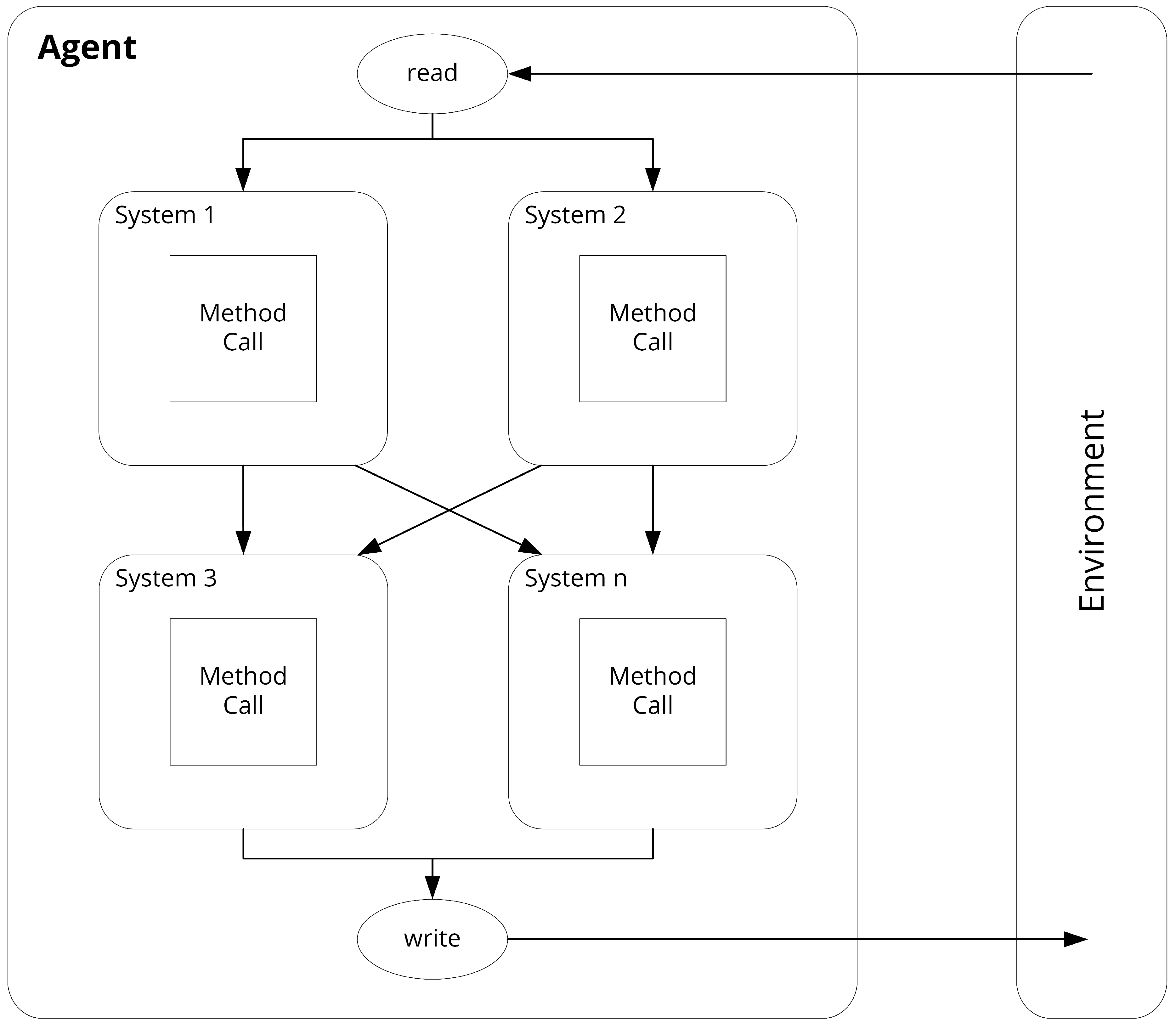
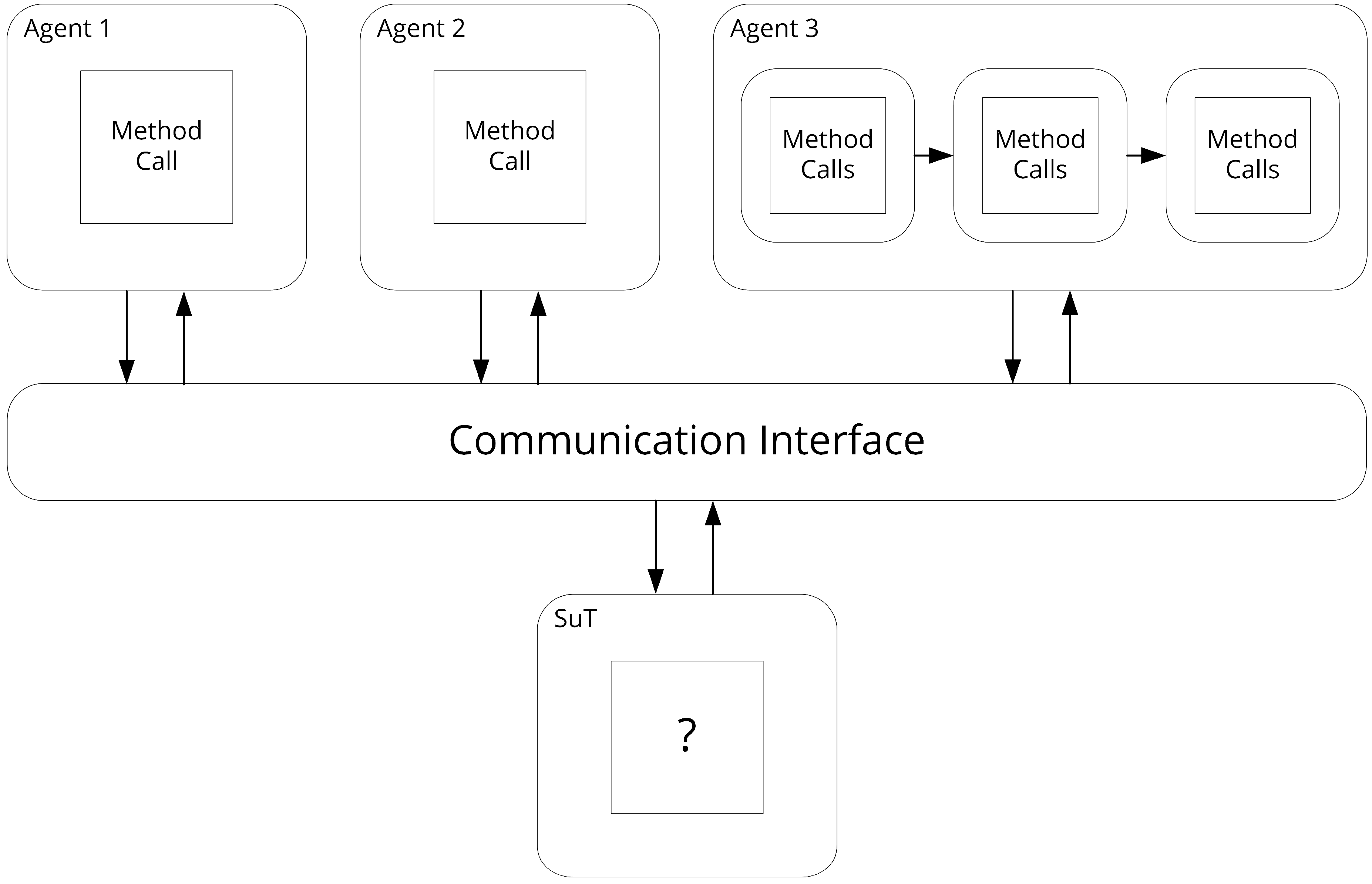
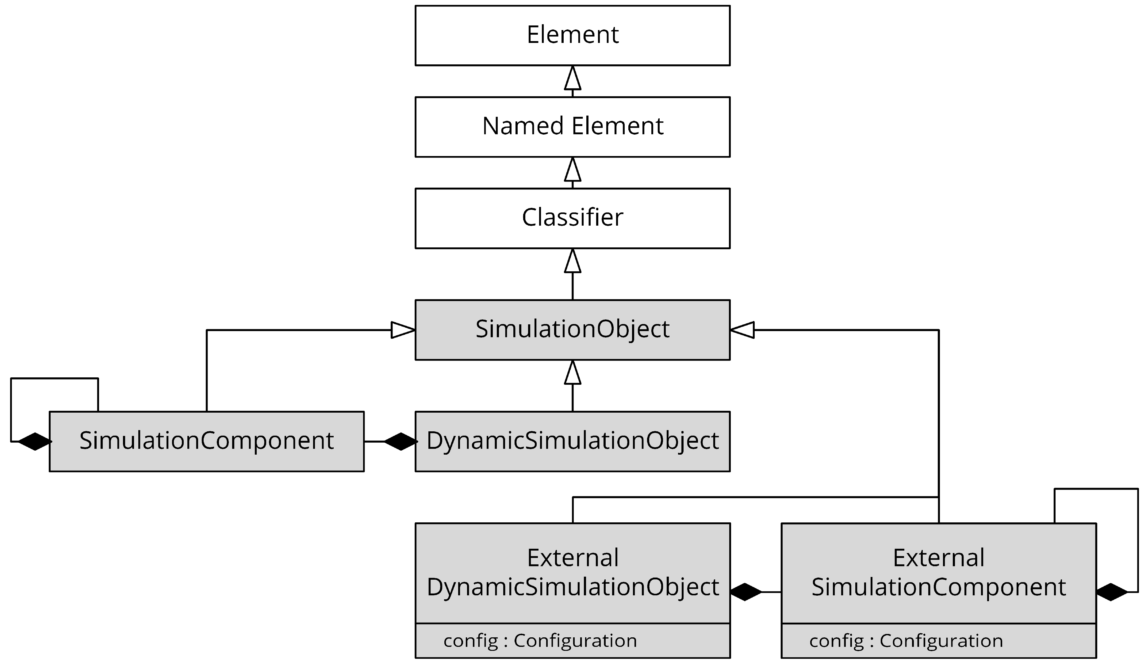
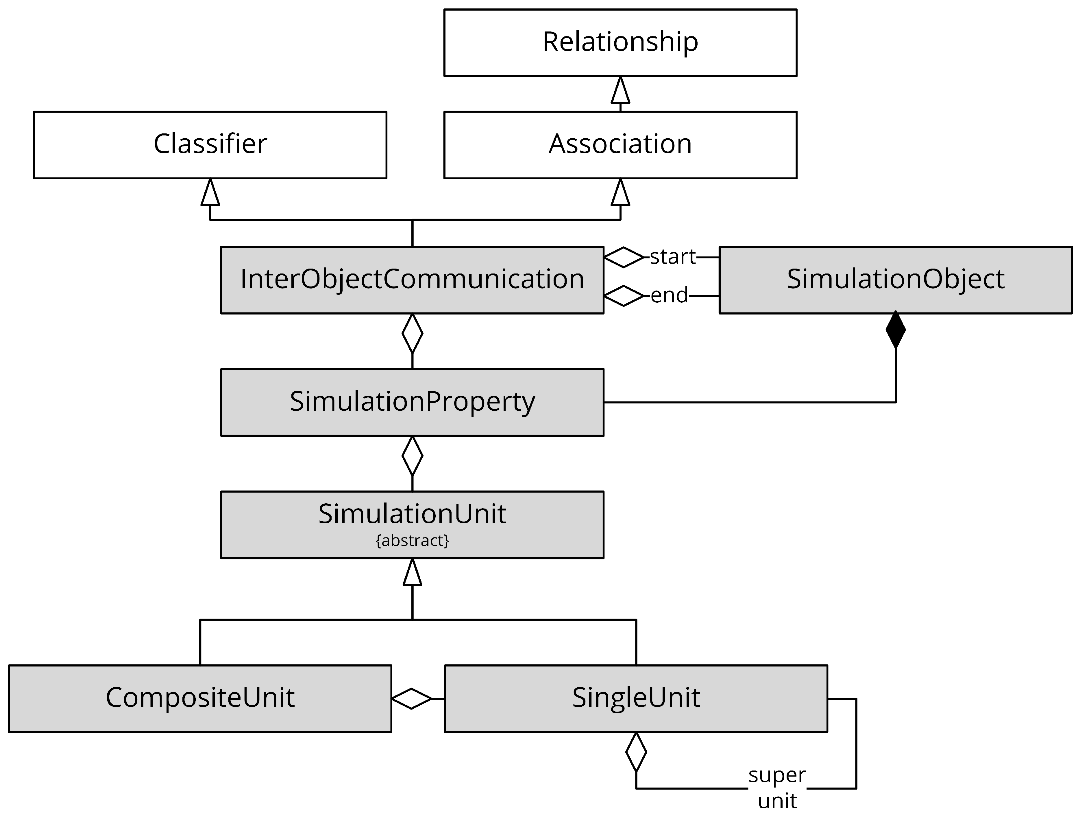
5.2. Nested Simulation Objects

In Section 3.2 and Section 3.3, it was already pointed out that the composition of a simulated traffic system can consist of modeled traffic participants with different levels of abstraction. A traffic participant as an agent within a simulation can be expressed by a monolithic model or consist of several nested subsystem models. In an analogous way, it must be possible to integrate a SuT in the simulation run as a holistic traffic participant substitute or in the manner of a subsystem of a modeled traffic participant. A mixture of these integration types is also conceivable. A possible simulation configuration with mixed abstraction levels and the integration of a SuT is exemplified in Figure 13.
The MOF-based meta-model on level M2 must therefore allow the nesting of dynamic simulation objects and the integration of external systems in the subsequent modeling layer. The following modeling concepts are proposed and used as a starting point for the above:
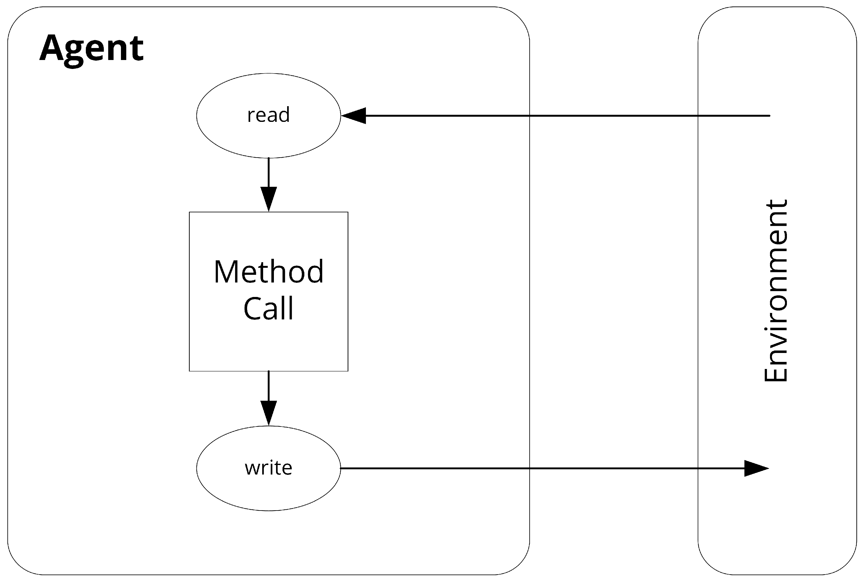
  • DynamicSimulationObject: Represents an entity of the simulation, which has inputs and outputs. It can therefore perceive and influence the simulation environment.
  • SimulationComponent: Represents a component, which is part of a DynamicSimulationObject. Has inputs and outputs that are linked to those of the parent object. SimulationComponents can be further nested analogous to the embedding in a DynamicSimulationObject.
  • ExternalDynamicSimulationObject: Represents a whole entity of the simulation, but instead of holding its own logic, it is only a wrapper in the sense of also having inputs and outputs, but not holding some internal logic and instead routing the in- and outputs to and from an external system or model via configuration options. In this way, a system to be tested can be integrated into the scenarios and thus also into the simulation runs, independent of its location.
  • ExternalSimulationComponent: Represents a component like the SimulationComponent, but in the manner of a wrapper like the ExternalDynamicSimulationObject.

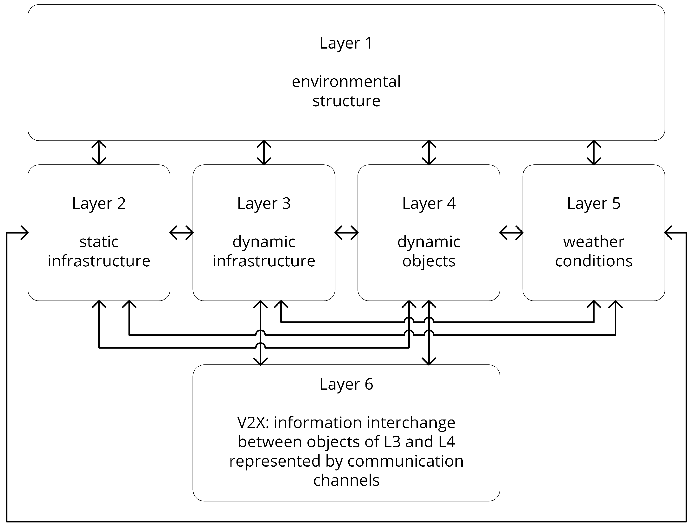
5.3. Organizing the Scenario Model

A traffic simulation consists not only of traffic participants but also of things that surround them. This starts with the environment in which they move. In terms of the maritime domain, this includes rivers, seas, coasts, and their characteristics. In this environment, there are physical things for traffic regulation (buoys, beacons, signs, etc.) as well as conceptual elements without physical representation (e.g., traffic separation areas and rules). Dynamic components can then be divided into two groups: dynamic infrastructure, such as buoys that can move in a limited spatial area in the water, and fully dynamic objects, such as traffic participants, that can move freely through the given environment. For many transportation systems, difficult weather conditions are a challenge because of the impact they have on the environment and its contents. These must therefore likewise be able to be modeled to ensure meaningful results. In order to structure these concepts and to limit the possible interactions among them, it is proposed to divide the model layer M1 into ontological layers, as well, and therefore to assign fixed interaction dependencies to them.
Aimed at the automotive domain, Bagschik et al. [50] proposed a five-layer ontology for modeling road traffic scenes, which reflects the previously described classification of concepts quite well. With slight adaptations to avoid domain-boundedness, this is used here. Also targeting the automotive domain, Bock et al. [51] have further extended this ontology with another layer reflecting digital information and communication. Since the various types of traffic networking are one of the concepts that have recently received a lot of attention in the context of autonomous vehicles, this layer is adapted here as well in order to be able to map channels for Vehicle-to-Vehicle (V2V) and Vehicle-to-Infrastructure (V2I) communication in a dedicated way. Figure 14 illustrates the adapted version of the six-layer approach that will further be used in this work.

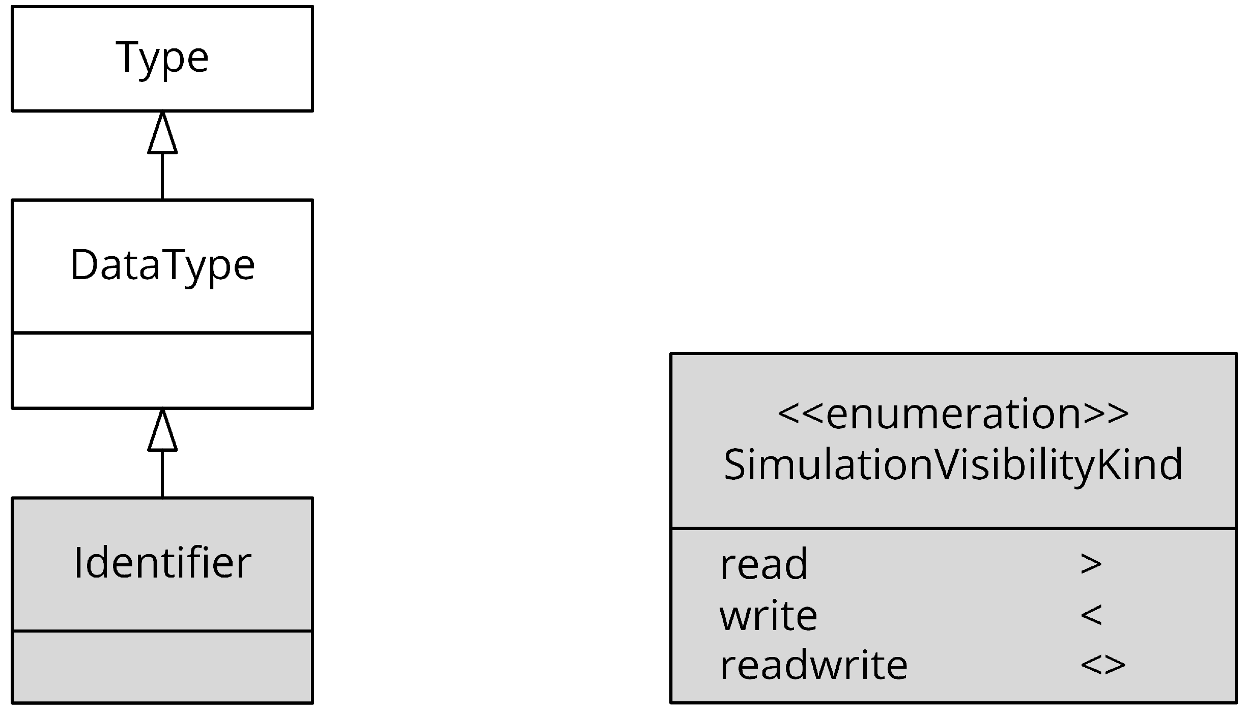
5.4. Intra-Layer Ontologies

In their work on Model-Driven Development, Atkinson and Kühne [49] introduced a further dimension of metamodeling in addition to the classical linguistic dimension. They call this second metamodeling dimension Ontological Metamodeling and characterize it as being concerned with describing what concepts exist in a certain domain and what properties they have. These new layers, labeled with O0 to On, reside within one of the linguistic layers. In the present work, this concept is applied within the M1 layer to increase the reusability of the models.
A reasonable division of the models on layer M1 is the following: a domain-independent model of traffic scenarios (possible element: traffic participant), based on this and thus further refining the elements a domain-specific model (possible element: vessel) and finally the level of instantiated concepts (possible element: a specific parameterized vessel). The last step further satisfies the definition of the snapshot dependency defined earlier. These three levels are therefore referred to in conclusion as O0, O1, and O2.
To further increase reusability, the concept of a domain library is introduced. This library is also a snapshot of the elements in the layer above and thus allows elements from the domain model to be fully parameterized and offered in terms of templates for scenario definition. For example, different vessel types can be predefined, which a user of the simulation can access and reuse later during scenario modeling.

5.5. Code-Integration

To incorporate the integration of the description of changes and behavior over time as indicated in Figure 12, it seems insufficient for a highly complex application, as a traffic simulation is, to rely on model-driven approaches such as UML flowcharts. The concept of modeling spaces could provide a solution. A modeling space (MS) is a modeling architecture based on a particular meta-metamodel. If the MOF meta-metamodel is used on the M3 level, one is in the MOF Modeling Space. In this modeling space, things of the real world (M0) can be described by the capabilities of the respective meta-metamodel. The same reality is described in the context of other modeling spaces, such as an EBNF (Extended Backus–Naur Form) space. One modeling space models the same set of real-world things as another modeling space, but in another way. Java code (and also C++ and other code) is a model since it represents an abstraction of reality. EBNF as its metasyntax, therefore, builds the foundation as the meta-metamodel (M3). The actual programming language grammar that one uses when writing programs is then content of M2. This could be, for example, the Java Grammar. The written code on the other hand is a model of a real-world concept [52]. It is easy to see that these two (and all other) modeling spaces are parallel to each other. Therefore, to achieve the set objective, it is proposed to create a link between models from two different modeling spaces. This means, in concrete terms, that a link in the form of a classpath or something similar can be defined within a dynamic object as part of a scenario. Thus, the static MOF-based object is enriched by a dynamic part in the form of code, e.g., Java code. Both submodels can then be merged in the step from M1 to M0 by model transformation to a common instance since our goal is executable simulation code.

5.6. Merging the Concepts

By bringing together the concepts discussed individually and by aligning them with the metamodeling process in accordance with MOF, an overall architecture is obtained. This is graphically illustrated once again in a holistic form in Figure 15. The resulting overall architecture thus represents the novel approach that is proposed to fulfill the requirements identified earlier for a simulation- and scenario-based V&V process of modern traffic systems.

6. Application

In this section, the previously constructed model-based multi-layered concept is prototypically applied in a proof of concept manner. For this purpose, it is shown how a MOF-compliant metamodel for modeling traffic simulation scenarios is created on the M2 layer based on existing UML metamodel elements. The most important elements of the created metamodel are then presented in a simplified graphical way as well as briefly explained. Using this metamodel, a simple maritime traffic scenario is then modeled to provide an example of the elements at the M1 layer and to prove the applicability of the novel approach presented in this work.

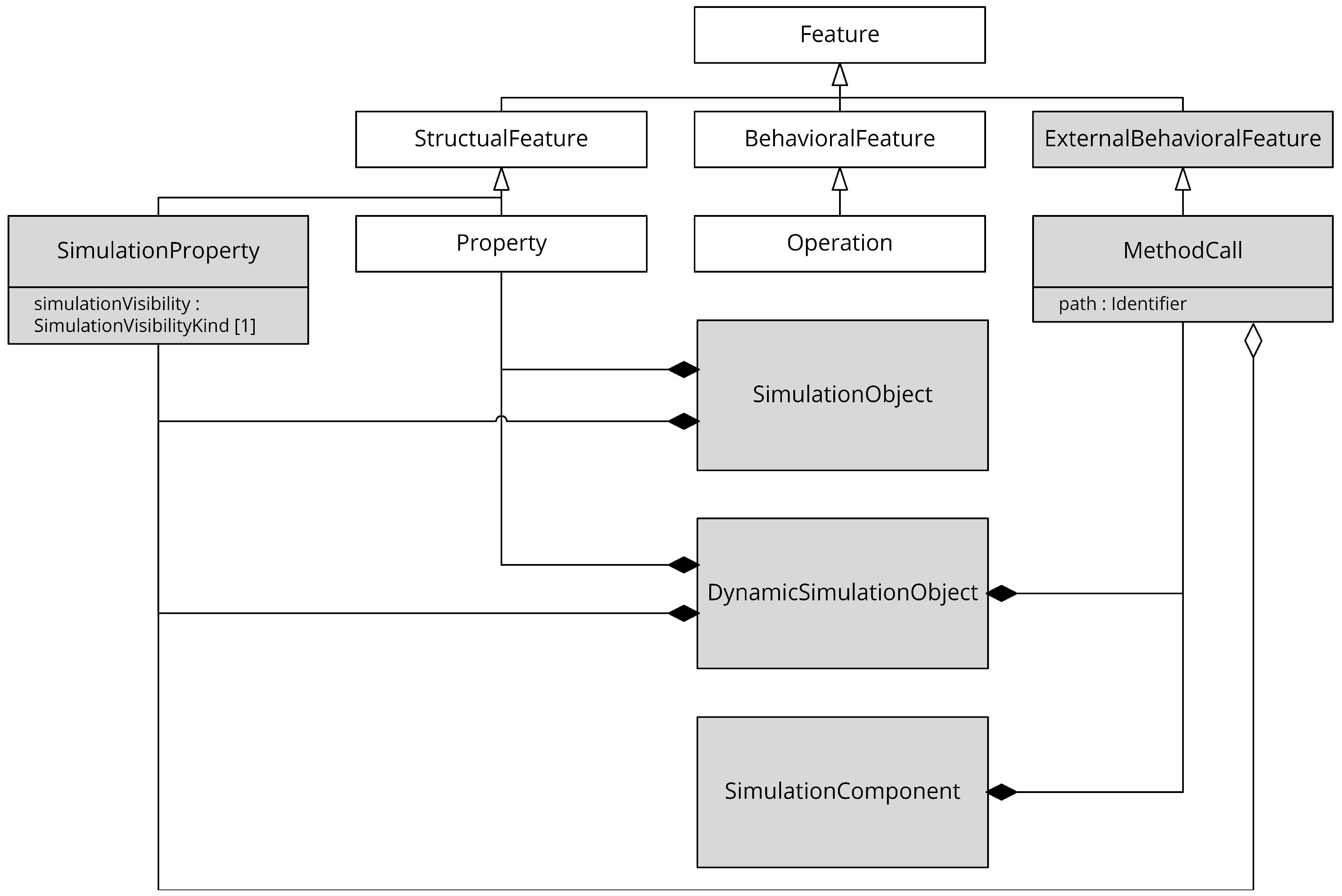
6.1. UML Metamodel Extension

As already briefly touched upon in Section 5.1, MOF and UML share a common core since the release of version two of UML. (In the further course, the term “UML” always refers to version two or higher.) This set of basic structural elements of UML is called UML Infrastructure [47]. MOF itself merges this UML core as the basis for modeling the meta-metamodeling language elements it provides [45]. Modeling, metamodeling, and meta-metamodeling elements are organized in packages within the OMG standards. The mentioned packages “MOF” and “UML::Core” are located within the M3 meta-metamodeling layer.
The approach presented here hooks in, in the form of a traffic simulation-specific metamodel, at the M2 level (cf. Figure 15). The question here was whether to create a completely new metamodel from the ground up or to extend an existing MOF-compliant metamodel. For the sake of efficiency and to adopt already established standards as much as possible, it was decided to use the second option. At the M2 level, UML is also located as a metamodeling language and uses the MOF meta-metamodel to model the elements it provides. The corresponding standard is called UML Superstructure [54]. Due to its widespread use, its maturity, and the fact that UML has established itself as a common modeling tool for various application domains, it was decided in the context of this work to implement the approach described in the previous section as a UML extension.
Despite its applicability to a wide range of application domains, UML does not provide all the necessary capabilities for modeling traffic scenarios that should be able to be simulated seamlessly in the sense of the proposed approach. The need to extend UML with the necessary concepts is therefore obvious. According to [54], the ability to customize UML to a particular domain is one of its greatest features. By creating customized variants, existing modeling tools and conventions defined by the UML specification can be used while making modeling simpler for the user.
UML offers two types of extension mechanisms [47]: a heavyweight extension mechanism and a lightweight extension mechanism. The use of so-called profiles provides the lightweight extension approach for extending UML capabilities, which can be used on the model level itself. Thus, no meta-level (M2) customizations are required when using profiles. Profiles are obtained by defining stereotypes that extend existing UML metaclasses for a specific purpose. In addition, tagged values and constraints can be created for the stereotyped elements. This extends the UML metamodel for different platforms or domains without violating the standard semantics. The implementation of a UML heavyweight extension is more complex than that of a lightweight extension. It makes a real change to the UML metamodel layer (M2) by adding new elements or modifying, constraining, or extending the existing elements. A heavyweight extension can fundamentally change the basic structure and behavior of UML. A heavyweight extension can be achieved by reusing packages, e.g., merging and importing packages and sub-packages, but excluding others. In addition, the extension of the UML metaclasses by the application of common modeling concepts such as inheritance, compositions, associations, etc. can be used for heavyweight extension.
Which of the two approaches to UML customization is more fitting depends on the nature of the intended application and how the (meta-) model will be used. If one wants to make simple customizations by adding new properties specific to a particular use case on top of the existing UML metaclasses, then a lightweight extension is an appropriate way to go. However, if one wants to extend the behavior and/or structure of UML, add constraints, or use the more complex features of UML such as redefinition, then a heavyweight extension is the better choice [55]. Since fundamental changes and new elements are needed to implement a metamodel for the previously proposed approach, a UML heavyweight extension was chosen. Among other things, new elements have to be introduced to model the simulation participants, new associations between those to model V2X communication as well as new data types and linking possibilities to integrate models from another modeling space (cf. Section 5.5). Figure 16 illustrates the relationships between the model packages and their interdependencies, where the new metamodel elements, created as part of the extension, are located in the Traffic Simulation Scenario Meta-Model (TSSMeta) package.

6.2. Traffic Simulation Scenario Metamodel

The new modeling elements in the TSSMeta package are linked by inheritance to at least one modeling element from the UML metamodel. The elements in the package TSSMeta are using metaclasses defined in the “UML::Classes::Kernel” package. The Kernel package defines the basic constructs used to define the UML superstructure metamodel, and most UML packages reuse them.
Figure 17, Figure 18, Figure 19, Figure 20 and Figure 21 show the newly introduced metaclasses, colored in gray. The central metaclass added is called SimulationObject and was created to replace one of the core elements of UML, the metaclass Class. SimulationObject extends the Classifier metaclass and therefore does not inherit the associations to Property and Attribute (Figure 17). This is purposeful because substitutes for both will be introduced later targeted at the ability to execute the model in a simulation. SimulationObject represents an object as a participant of the simulation, which is static in the sense of not being able to change its values in the run of the simulation. Four metaclasses inherit directly from SimulationObject and represent the core modeling concepts proposed in Section 5.2. A DynamicSimulationObject is a SimulationObject that is able to change its values throughout the simulation run and has the ability to link to functions from another modeling space like it was outlined in Section 5.5. It also can contain SimulationComponents, which in turn can contain further nested SimulationComponents, to which the function calls are forwarded at each simulation time step if present. The two classes with the prefix “external” are structured analogously but do not link to executable code from another modeling space; rather, they contain a configuration for connecting external models and systems.
In order to introduce a property, which is focused on the communication of the simulation participants via a common environment, the metaclass SimulationProperty was created (Figure 18). It inherits directly from StructuralFeature and can therefore be used similar to a classic Property. The important parameter here is simulationVisibility, which takes a value from the enumeration SimulationVisibilityKind (Figure 19) and controls whether the property’s value should be visible and usable for other simulation participants through the shared environment, should be read from the shared environment, or both. To realize the linkage of executable code, the metaclass MethodCall was introduced. It inherits directly from the also newly introduced ExternalBehavioralFeature and substitutes for the classic operations of a UML class. Instead of defining a method signature, an identifier is specified here (cf. Figure 19), which directly identifies a method from a parallel modeling space. In addition, a MethodCall contains references to the SimulationProperties that are to be passed to the linked method.
Figure 18. Simplified view on the internal structure of the newly introduced SimulationObject related meta-classes (cf. Figure 17). White boxes represent existing UML metamodel elements and gray boxes represent newly added ones.
Jmse 09 00673 g018
Figure 19. Simplified view on the added datatype Identifier that holds the identifier of a coded function from a parallel modeling space. The class should be specialized for specific programming languages such as Java. Additionally, the new enumeration SimulationVisibilityKind is shown, which holds the possible visibility values of SimulationProperties. White boxes represent existing UML metamodel elements and gray boxes represent newly added ones.
Jmse 09 00673 g019
In order to be able to model not only the general exchange of data via the common simulation environment but also dedicated 1-to-1 channels in the sense of V2X communication, a special association is required. This is fulfilled by the metaclass InterObjectCommunication, which contains two references to simulation objects and to the SimulationProperties of these, which are to be exchanged (Figure 20).
Figure 20. Simplified view on the introduced InterObjectCommunication meta-class that inherits from classifier and association inspired by the UML-owned meta-class AssociationClass. Additionally, the structure of the meta-class SimulationUnit is shown, which represents the unit of a value of a SimulationProperty (cf. Figure 18). White boxes represent existing UML metamodel elements and gray boxes represent newly added ones.
Jmse 09 00673 g020
Additionally shown in Figure 20 is the structure of a SimulationProperty. In addition to the usual parameters such as name and value, a SimulationProperty also contains a reference to a SimulationUnit. This ensures a uniform understanding of the transferred values within the simulation. A SimulationUnit can be a single unit such as Meter with the character m or a CompositeUnit referencing two or more single units. An example of the latter is a position in the geographic coordinate system (lat, long). In order to be able to convert different units of measurement automatically, factorial related units refer to each other and specify the corresponding factor. An example for such a super unit is km/h for the SingleUnit m/h with a factor of 1000. Other conversions such as kn to km/h could be integrated analogously later.
The last important part of the created metamodel is the Limitation metaclass, which is specialized by two other metaclasses. Constraint has the purpose to represent limitations that exist naturally, i.e., are caused by the mere presence of simulated objects. This can be, for example, the fact that a ship cannot sail to certain coordinates because there are landmasses or other ships present there. A restriction, on the other hand, represents artificially created restrictions, such as the right-hand driving rule, as it is common in most European countries.
Figure 21. Simplified view on the metaclass Limitation and its specializations. White boxes represent existing UML metamodel elements and gray boxes represent newly added ones.
Jmse 09 00673 g021

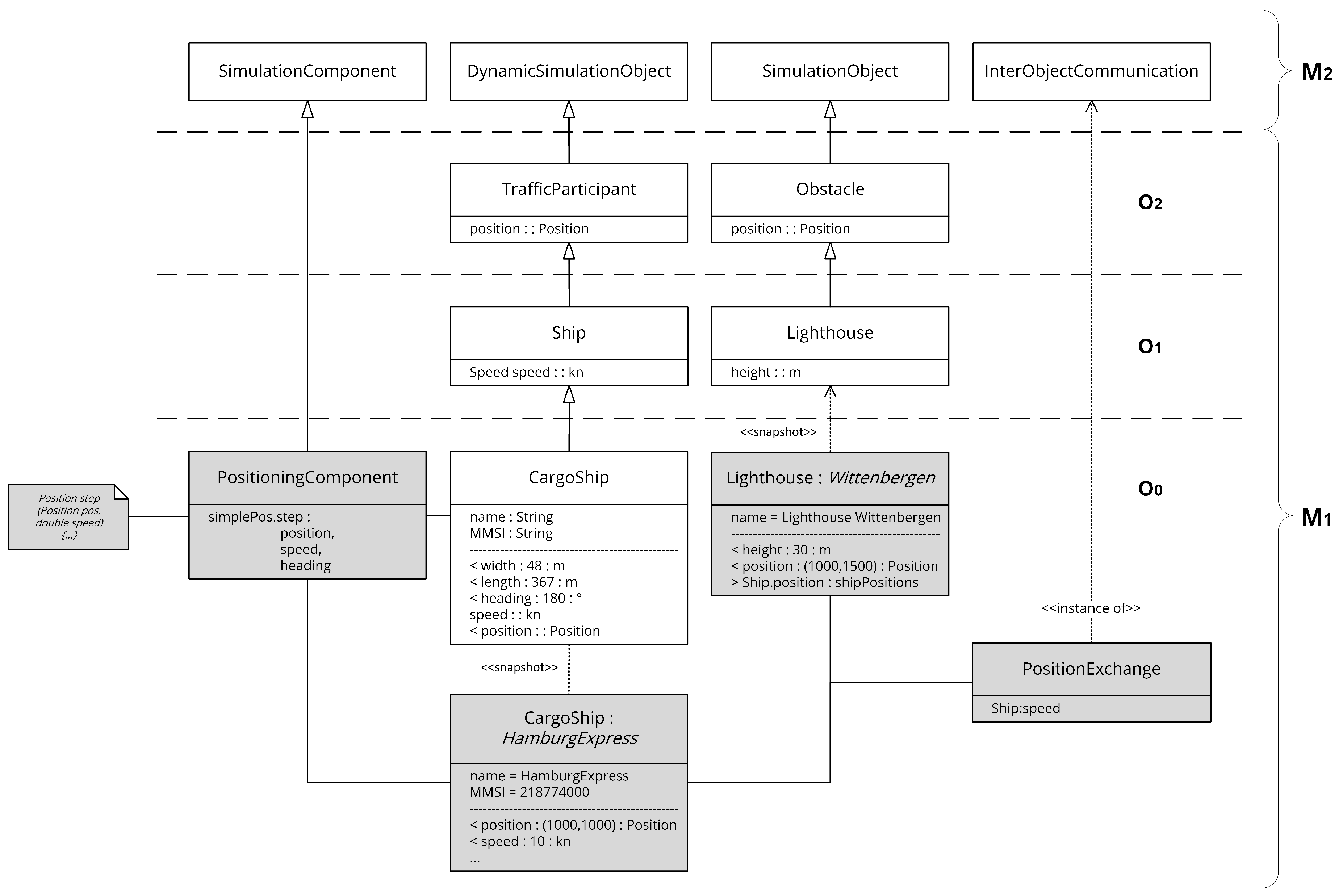
6.3. Modeling of a Simple Maritime Scenario

To demonstrate the general applicability of the entire approach, a simple minimal example of a maritime traffic scenario was modeled using the metamodel TSSMeta, which was created above through a heavyweight UML extension (Figure 22). The scenario consists of the cargo ship “HamburgExpress” and the lighthouse “Wittenbergen”, which are located at certain positions in a fictional two-dimensional space. The vessel has an initial speed of 10 knots and a heading of 180°. For each simulation step, the new position is to be calculated from the current position, the current speed, and the current heading. A method already exists for this, which was modeled in a parallel modeling space in the EBNF-based programming language Java. Apart from general properties that the lighthouse could visually perceive in the real world, the current speed of the vessel is to be explicitly transmitted to the lighthouse via a Vessel-to-Infrastructure channel (V2I).
The first step in modeling such a scenario is now to model the elements inside the O2 layer. As previously specified, this layer is to contain domain-independent models of concepts of traffic scenarios. By inheriting DynamicSimulationObject and SimulationObject, the two elements TrafficParticipant and Obstacle were therefore modeled.
The model is then further refined at the O1 layer with reference to a specific traffic domain—in this specific case, the maritime domain. TrafficPariticipant thus is specialized to Ship and Obstacle to Lighthouse by adding further properties in the form of SimulationProperties (cf. Section 6.2).
If Figure 15 is looked at again, it is noticeable that layer O0 is divided into two sections. This dichotomy is also present here due to the further specialization of Ship by CargoShip. By defining some default values, a template is created for this type of ship, which can be reused later for modeling other scenarios.
Finally, the elements specialized up to this point are initialized in terms of UML objects; all values are defined accordingly and connections and associations are defined. These elements and structures then constitute the actual scenario model, which represents the scenario previously described in natural language.
As intended, each of the layers can subsequently be reused, adapted, or extended for other scenarios. In terms of reusability, the Domain Library, represented here by the object CargoShip, is of particular importance, as it allows predefined building blocks to be created once for certain classes of objects and reused later, which has the potential to significantly reduce the workload.

7. Discussion

The proposed novel model-based and multi-layered approach fulfills the requirements identified in this work or at the very least forms a valid basis to empower the fulfillment of the requirement in question. The fulfillment of the first requirement for an extensible and customizable foundation was demonstrated without a doubt. This was realized on the one hand by the use of standards aimed at this particular challenge such as MDA and MOF, and on the other hand through the implementation of the proposed meta-layer and the subsequent application of this by the modeling of a simple example. The second requirement for the seamless and direct integration of a SuT during scenario modeling is fulfilled by the elements of the metamodel specifically designed for this purpose. Although their use was not demonstrated in the context of the exemplary modeling, it is clear from the inheritance structure within the metamodel that the use of the corresponding meta-concepts is readily possible. The fulfillment of the sub-requirement that the simulation system itself does not need to be adapted emerges from the fact that the configuration of the connection, when using the presented approach, is part of the scenario and can be inherited by the simulation model through model transformation. The fulfillment of the third and thus last requirement that a holistic approach is to be pursued also results clearly on the one hand from the intended use of model transformations and on the other hand from the inclusion of the simulation model as layer M0 from the very beginning. This has led to the simulation itself being considered at every step, such as the development of the UML extension-based metamodel, deliberately bypassing the strict separation of simulation and scenario models often prevalent in existing solutions.
The implementation of a heavyweight MOF-based extension of UML has introduced some complexity and led to further necessary steps (more on this in the following section). Some UML-based very specialized modeling languages exist, often based on pure lightweight extensions. One of these is SysML, which follows an approach similar to the core of this work with the concepts of ports and flows within Internal Block Diagrams and Block Definition Diagrams. It might therefore be worth looking at whether SysML could be a possible second approach, possibly less flexible but also less complex in its basic structure.

8. Conclusions and Outlook

In this work, a novel model-based multi-layered approach to describe traffic scenarios on a technical level was developed and presented. The models and meta-models developed and presented here do not claim to be exhaustive or production-ready by any means, much more this work represents a thought-provoking impulse for a new approach to the modeling of traffic scenarios that are to be simulated in the context of V&V, and thus a possible direction of development for subsequent work. For this purpose, the importance of V&V in the development of (highly) automated and autonomous traffic systems was presented, and requirements for the corresponding scenario modeling were thoroughly elaborated based on common processes. In order to meet these requirements, a novel model-based approach, whose very essence is shown in Figure 15, was developed, taking influence from existing (partial) concepts. The approach was then implemented in a proof-of-concept manner by a heavyweight Meta Object Facility (MOF) based extension of the Unified Modeling Language (UML). The basic feasibility was then partly derived from the underlying standards and additionally shown by a minimal maritime example. To achieve the overall goal and make the presented approach fully operational, further work is needed and intended. Some of these steps are the definition of precise rules and constraints for the usage of the created metamodel; among others, the Object Constraint Language (OCL) from the UML-related family of standards could be suitable for this purpose. The most important and next step to be considered is probably the model transformation in the sense of MDA, in order to obtain the actual executable simulation model from the scenario model. For this, specific transformation rules need to be created and the necessary processes to be realized.
A suitable technology for the structured implementation and execution of the simulation itself would be the High Level Architecture (HLA) [56]. The approach described in this work aims to represent each traffic participant as a separate agent and to have them communicate with each other through a shared central environment or, more precisely, through a communication layer. A very similar structure is also reflected by HLA using the concepts of a central Run-Time Infrastructure (RTI) and separated federates who can share data using the RTI. Using the publish-subscribe pattern offered by HLA, dedicated communication between two traffic participants, as modeled here by the metaclass InterObjectCommunication, could also be realized. For these reasons, it is planned to make the approach presented here executable using HLA structures and runtime models by implementing a model transformation process transforming the models shown not only into executable program code but also into Object Model Template (OMT) conforming models that are required by HLA.
Additionally, the presented metamodel may be further extended to cover additional use cases in the context of V&V of (highly) automated or autonomous traffic systems. For example, to enable the automated execution of a set of variations of a base scenario, the possibility to model parameter ranges instead of fixed values could be introduced.

Author Contributions

Conceptualization, methodology, implementation, validation, investigation, visualization, writing—original draft preparation, and writing—review and editing, D.R.; supervision, A.H. All authors have read and agreed to the published version of the manuscript.

Funding

This research received no external funding.

Informed Consent Statement

Not applicable.

Data Availability Statement

Request to the corresponding author of this article.

Conflicts of Interest

The authors declare no conflict of interest.

References

  1. Bräuninger, M.; Fiedler, R.; Friedrich, T.; Küchle, J.; Maatsch, S.; Schlennstedt, J.; Stiller, S.; Teuber, M.-O. Volks-Wirtschaftliche Bedeutung des Hamburger Hafens: Untersuchung der Regional—Und Gesamtwirtschaftlichen Bedeutung des Hamburger Hafens [Economic Significance of the Port of Hamburg: Investigation of the Regional and Overall Economic Significance of the Port of Hamburg]; Institute of Shipping Economics and Logistics: Hamburg, Germany, 2021; Available online: https://www.hamburg-port-authority.de/fileadmin/user_upload/BeschaeftigungsstudieHafenHamburg2019_Endbericht_final.pdf (accessed on 1 April 2021).
  2. Lemper, B.; Maatsch, S.; Fiedler, R.; Bräuninger, M.; Holocher, K.-H. Untersuchung der Volkswirtschaftlichen Bedeutung der Deutschen See—Und Binnenhäfen auf Grundlage Ihrer Beschäftigungswirkung. Final Report [Investigation of the Economic Importance of German Sea and Inland Ports Based on Their Effect on Employment]; Federal Ministry of Transport and Digital Infrastructure: Bremen, Germany, 2019; Available online: https://www.isl.org/public/studienergebnisse/Beschaeftigungseffekte_BMVI_Endbericht5-Final.pdf (accessed on 18 April 2021).
  3. International Maritime Organization. Maritime Safety Committee (MSC): 100th Session, 3–7 December 2018; International Maritime Organization (IMO): London, UK, 2018; Available online: https://www.imo.org/en/MediaCentre/MeetingSummaries/Pages/MSC-100th-session.aspx (accessed on 15 December 2020).
  4. Lenz, B.; Fraedrich, E. Gesellschaftliche und Individuelle Akzeptanz des Autonomen Fahrens [Social and individual acceptance of autonomous driving]. In Autonomes Fahren: Technische, Rechtliche und Gesellschaftliche Aspekte; Maurer, M., Gerdes, J.C., Lenz, B., Winner, H., Eds.; Springer: Berlin, Germany, 2015; pp. 639–660. [Google Scholar]
  5. SAE International. Taxonomy and Definitions for Terms Related to on-Road Motor Vehicle Automated Driving Systems: J3016, 2018. Available online: https://www.sae.org/standards/content/j3016_201806/ (accessed on 9 December 2020).
  6. Federal Ministry for Economic Affairs and Energy. Pegasus Method: An Overview. Germany, 2019. Available online: https://www.pegasusprojekt.de/files/tmpl/Pegasus-Abschlussveranstaltung/PEGASUS-Gesamtmethode.pdf (accessed on 10 December 2020).
  7. Brinkmann, M.; Bode, E.; Lamm, A.; Maelen, S.V.; Hahn, A. Learning from automotive: Testing maritime assistance systems up to autonomous vessels. In OCEANS 2017—Aberdeen; IEEE: Piscataway, NJ, USA, 2017; pp. 1–8. [Google Scholar] [CrossRef]
  8. International Organization for Standardization (ISO). Ships and Marine Technology—Computer Applications—General Principles for the Development and Use of Programmable Electronic Systems in Marine Applications: ISO 17894:2005, 2005. Available online: https://www.iso.org/standard/31619.html (accessed on 15 April 2021).
  9. Rüssmeier, N.; Lamm, A.; Hahn, A. A generic testbed for simulation and physical-based testing of maritime cyber-physical system of systems. In Proceedings of the International Maritime and Port Technology and Development Conference and International Conference on Maritime Autonomous Surface Ships, Trondheim, Norway, 13–14 November 2019; Volume 1357, p. 012025. [Google Scholar] [CrossRef]
  10. Wachenfeld, W.; Winner, H. Die Freigabe des Autonomen Fahrens [The approval of autonomous driving]. In Autonomes Fahren: Technische, Rechtliche und Gesellschaftliche Aspekte; Maurer, M., Gerdes, J.C., Lenz, B., Winner, H., Eds.; Springer: Berlin, Germany, 2015; pp. 439–464. [Google Scholar]
  11. Lamm, A.; Hahn, A. Towards critical-scenario based testing with maritime observation data. In Proceedings of the 2018 OCEANS—MTS/IEEE Kobe Techno-Oceans (OTO), Kobe, Japan, 28–31 May 2018. [Google Scholar] [CrossRef]
  12. Akkermann, A.; Hjollo, B.A. Scenario-based V&V in a maritime co-simulation framework. In Proceedings of the 2019 Spring Simulation Conference (SpringSim), Tucson, AZ, USA, 29 April–2 May 2019; pp. 1–12. [Google Scholar] [CrossRef]
  13. Hanke, T. Virtual Sensorics: Simulated Environmental Perception for Automated Driving Systems. Dissertation Thesis, Technische Universität München (TUM), München, Germany, 2020. Available online: http://nbn-resolving.de/urn/resolver.pl?urn:nbn:de:bvb:91-diss-20200529-1519952-1-7 (accessed on 18 February 2021).
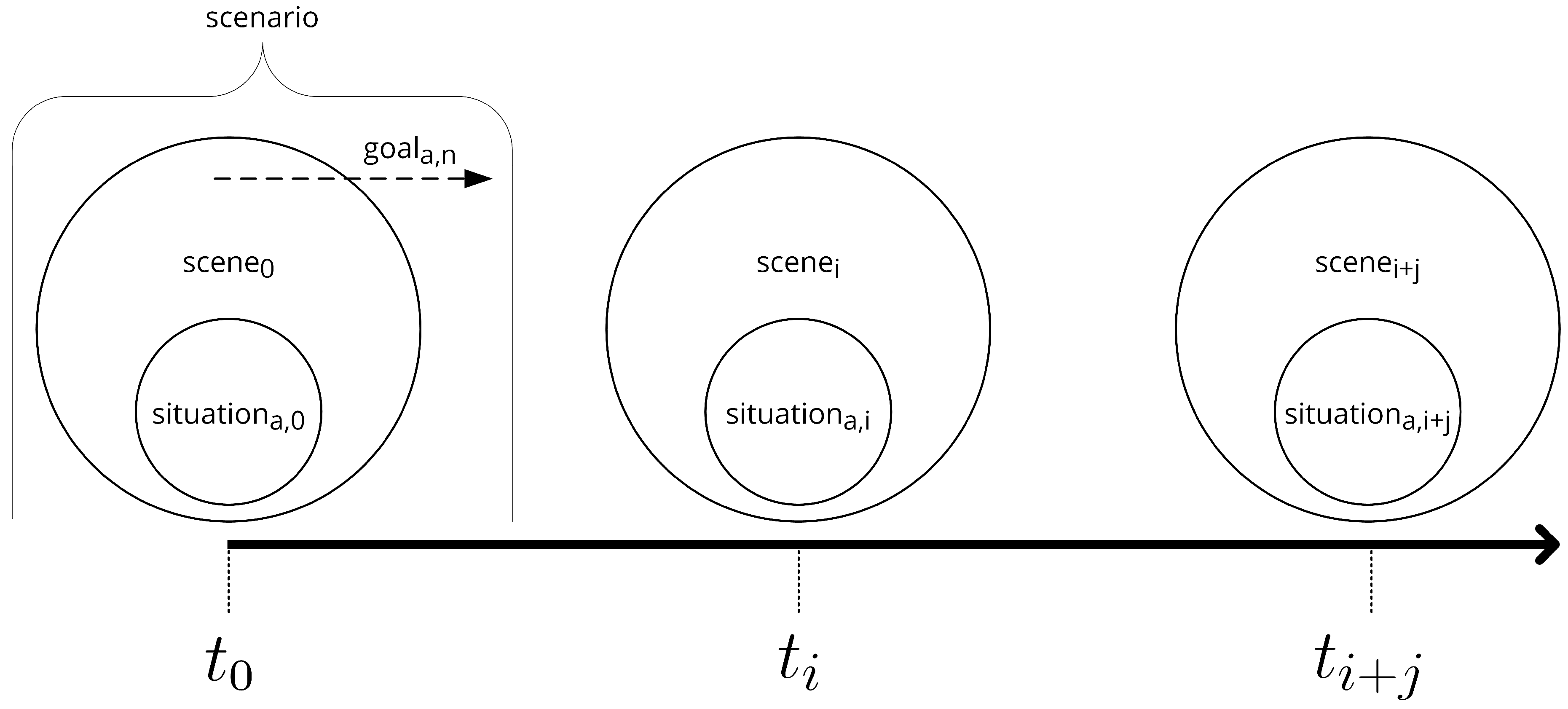
  14. Ulbrich, S.; Menzel, T.; Reschka, A.; Schuldt, F.; Maurer, M. Defining and substantiating the terms scene, situation, and scenario for automated driving. In Proceedings of the 18th International Conference on Intelligent Transportation Systems, Gran Canaria, Spain, 15–18 September 2015; pp. 982–988. [Google Scholar] [CrossRef]
  15. Wuellner, T.; Feuerstack, S.; Hahn, A. Clustering environmental conditions of historical accident data to efficiently generate testing sceneries for maritime systems. In Model-Based Safety and Assessment; Papadopoulos, Y., Aslansefat, K., Katsaros, P., Bozzano, M., Eds.; Springer: Berlin, Germany, 2019; pp. 349–362. [Google Scholar]
  16. Ding, W.; Chen, B.; Xu, M.; Zhao, D. Learning to collide: An adaptive safety-critical scenarios generating method. In Proceedings of the 2020 IEEE/RSJ International Conference on Intelligent Robots and Systems (IROS), Las Vegas, NV, USA, 24 October–24 January 2021; pp. 2243–2250. [Google Scholar] [CrossRef]
  17. International Organization for Standardization (ISO) Road Vehicles—Functional Safety ISO/FDIS 26262, 2018. Available online: https://www.iso.org/standard/68383.html (accessed on 16 April 2021).
  18. Balaji, S.; Sundararajan Murugaiyan, M. Waterfall vs. v-model vs. agile: A comparative study on SDLC. Int. J. Inf. Technol. 2012, 2, 26–30. [Google Scholar]
  19. International Organization for Standardization (ISO); International Electrotechnical Commission (IEC); Institute of Electrical and Electronics Engineers (IEEE). Systems and Software Engineering—Systems Life Cycle Processes: ISO/IEC/IEEE 15288:2015, 2015. Available online: https://www.iso.org/standard/63711.html (accessed on 22 April 2021).
  20. Koopman, P.; Wagner, M. Challenges in autonomous vehicle testing and validation. SAE Int. J. Transp. Saf. 2016, 4, 15–24. [Google Scholar] [CrossRef] [Green Version]
  21. Brinkmann, M. Physikalische Testfeld-Architektur für die Unterstützung der Entwicklung von Automatisierten Schiffsfüh-Rungssystemen [Physical Test Bed Architecture to Support the Development of Automated Ship Piloting Systems]. Dissertation Thesis, Carl von Ossietzky Universität Oldenburg, Oldenburg, Niedersachsen, Germany, 2018. [Google Scholar]
  22. Brinkmann, M.; Hahn, A. Testbed architecture for maritime cyber physical systems. In Proceedings of the 2017 IEEE 15th International Conference on Industrial Informatics (INDIN), Emden, Germany, 24–26 July 2017. [Google Scholar]
  23. Pfeffer, R.; Leichsenring, T. Continuous Development of highly automated driving functions with vehicle-in-the-loop using the example of euro NCAP scenarios. In Simulation and Testing for Vehicle Technology; Gühmann, C., Riese, J., von Rüden, K., Eds.; Springer: Berlin, Germany, 2016; pp. 33–42. [Google Scholar] [CrossRef]
  24. Ghadai, P.; Shree, L.P.; Chhatria, L.; Prasad, R. A study on agent based modelling for traffic simulation. Int. J. Comput. Sci. Inf. Technol. 2016, 7, 932–936. [Google Scholar]
  25. Russell, S.J.; Norvig, P. Artificial Intelligence: A Modern Approach, 3rd ed.; Pearson: London, UK, 2016. [Google Scholar]
  26. Steidel, M.; Hahn, A. MTCAS—An assistance system for collision avoidance at sea. In Proceedings of the 18th International Conference on Computer and IT Applications in the Maritime Industries, Tullamore, Ireland, 25–27 March 2019. [Google Scholar]
  27. Maier, M.W. Architecting principles for systems-of-systems. Syst. Eng. 1998, 1, 267–284. [Google Scholar] [CrossRef]
  28. International Organization for Standardization (ISO); International Electrotechnical Commission (IEC); Institute of Electrical and Electronics Engineers (IEEE). Systems and Software Engineering—Software Life Cycle Processes: ISO/IEC/IEEE 12207, 2017. Available online: https://www.iso.org/standard/63712.html (accessed on 14 April 2021).
  29. Weber, N.; Frerichs, D.; Eberle, U. A simulation-based, statistical approach for the derivation of concrete scenarios for the release of highly automated driving functions. In Proceedings of the GMM-Fachbericht 95: Automotive meets Electronics Beiträge, Dortmund, Germany, 10–11 March 2020; Volume 95, pp. 116–121. [Google Scholar] [CrossRef]
  30. Fremont, D.J.; Kim, E.; Pant, Y.V.; Seshia, S.A.; Acharya, A.; Bruso, X.; Wells, P.; Lemke, S.; Lu, Q.; Mehta, S. Formal scenario-based testing of autonomous vehicles: From simulation to the real world. In Proceedings of the 2020 IEEE 23rd International Conference on Intelligent Transportation Systems (ITSC), Rhodes, Greece, 20–23 September 2020; pp. 1–8. [Google Scholar] [CrossRef]
  31. Smogeli, Ø.R.; Ludvigsen, K.B.; Jamt, L.; Vik, B.; Nordahl, H.; Kyllingstad, L.T.; Yum, K.K.; Zhang, H. Open simulation platform—An open-source project for maritime system co-simulation. In Proceedings of the 19th International Conference on Computer and IT Applications in the Maritime Industries: COMPIT’20, Pontignano, Italy, 17–19 August 2020; pp. 239–253. [Google Scholar]
  32. OSP Interface Specification: OSP-IS 1.0., 2020. Available online: https://opensimulationplatform.com/assets/osp-is-1.0.pdf (accessed on 19 November 2020).
  33. Hahn, A.; Noack, T. eMaritime integrated reference platform. In Proceedings of the Deutscher Luft—und Raumfahrtkongress 2016. Deutsche Gesellschaft für Luft—und Raumfahrt—Lilienthal-Oberth e.V., Braunschweig, Germany, 13–15 September 2016; Available online: http://www.dglr.de/publikationen/2016/420297.pdf (accessed on 29 April 2021).
  34. Schweigert, S.; Gollücke, V.; Hahn, A.; Bolles, A. Haggis: A modelling and simulation platform for e-maritime technology assessment. In Proceedings of the INT-NAM 2014, 2nd International Symposium on Naval Architecture and Maritime, Istanbul, Turkey, 23–24 October 2014; pp. 733–742. [Google Scholar]
  35. Dosovitskiy, A.; Ros, G.; Codevilla, F.; Lopez, A.; Koltun, V. CARLA: An Open Urban Driving Simulator. In Proceedings of the 1st Annual Conference on Robot Learning, Mountain View, CA, USA, 13–15 November 2017; Volume 78, pp. 1–16. Available online: http://proceedings.mlr.press/v78/dosovitskiy17a.html (accessed on 12 March 2021).
  36. Zapridou, E.; Bartocci, E.; Katsaros, P. Runtime verification of autonomous driving systems in CARLA. In LNCS Sublibrary: SL2—Programming and Software Engineering; Deshmukh, J., Ničković, D., Eds.; Springer: Berlin, Germany, 2020; Volume 12399, pp. 172–183. [Google Scholar]
  37. Rong, G.; Shin, B.H.; Tabatabaee, H.; Lu, Q.; Lemke, S.; Mozeiko, M.; Boise, E.; Uhm, G.; Gerow, M.; Mehta, S.; et al. LGSVL simulator: A high fidelity simulator for autonomous driving. In Proceedings of the 2020 IEEE 23rd International Conference on Intelligent Transportation Systems (ITSC), Rhodes, Greece, 20–23 September 2020; pp. 1–6. [Google Scholar] [CrossRef]
  38. Foretellix Ltd. Measurable Scenario Description Language Reference, version 20.10; Foretellix Ltd: Tel Aviv, Israel, 2020; Available online: https://www.foretellix.com/open-language/ (accessed on 29 April 2021).
  39. Association for Standardization of Automation and Measuring Systems. ASAM SIM Guide: Standardization for Highly Automated Driving; ASAM e.V.: Höhenkirchen-Siegertsbrunn, Germany, 2021. [Google Scholar]
  40. Association for Standardization of Automation and Measuring Systems. In ASAM OpenSCENARIO V1.1.0 User Guide; ASAM e.V.: Höhenkirchen-Siegertsbrunn, Germany, 2021; Available online: https://www.asam.net/standards/detail/openscenario/ (accessed on 29 April 2021).
  41. Damm, W.; Kemper, S.; Möhlmann, E.; Peikenkamp, T.; Rakow, A. Using traffic sequence charts for the development of HAVs. In Proceedings of the SEE & 3AF (Chairs), ERTS 2018, Toulouse, France, January 2018; Available online: https://hal.archives-ouvertes.fr/hal-01714060 (accessed on 14 August 2020).
  42. Damm, W.; Möhlmann, E.; Peikenkamp, T.; Rakow, A. A formal semantics for traffic sequence charts. In Lecture Notes in Computer Science. Principles of Modeling; Lohstroh, M., Derler, P., Sirjani, M., Eds.; Springer: Berlin, Germany, 2018; pp. 182–205. [Google Scholar]
  43. Fremont, D.J.; Dreossi, T.; Ghosh, S.; Yue, X.; Sangiovanni-Vincentelli, A.L.; Seshia, S.A. Scenic: A language for scenario specification and scene generation. In Proceedings of the 40th ACM SIGPLAN Conference on Programming Language Design and Implementation, Phoenix, AZ, USA, 22–26 June 2019; pp. 63–78. [Google Scholar] [CrossRef] [Green Version]
  44. Object Management Group. Model Driven Architecture (MDA): MDA Guide Rev. 2.0 (OMG Document ormsc/2014-06-01), 2014. Available online: https://www.omg.org/cgi-bin/doc?ormsc/14-06-01 (accessed on 15 February 2021).
  45. Object Management Group (OMG). Meta Object Facility (MOF) Core Specifiaction, Meta Object Facility 2.5.1; Object Management Group: Needham, MA, USA, 2016; Available online: https://www.omg.org/spec/MOF/2.5.1/PDF (accessed on 8 July 2019).
  46. Object Management Group (OMG). Unified Modeling Language (UML), version 2.5.1 (formal/2017-12-05); Object Management Group (OMG): Milford, MA, USA, 2017; Available online: https://www.omg.org/spec/UML/ (accessed on 14 April 2021).
  47. Object Management Group (OMG). Unified Modeling Language (UML), Infrastructure, version 2.4.1 (formal/2011-08-05); Object Management Group (OMG): Milford, MA, USA, 2011; Available online: https://www.omg.org/spec/UML/2.4.1/Infrastructure/PDF (accessed on 14 April 2021).
  48. Seidewitz, E. What models mean. IEEE Softw. 2003, 20, 26–32. [Google Scholar] [CrossRef]
  49. Atkinson, C.; Kühne, T. Model-driven development: A metamodeling foundation. IEEE Softw. 2003, 20, 36–41. [Google Scholar] [CrossRef] [Green Version]
  50. Bagschik, G.; Menzel, T.; Maurer, M. Ontology based scene creation for the development of automated vehicles. In Proceedings of the 2018 IEEE Intelligent Vehicles Symposium (IV), Changshu, China, 26–30 June 2018; pp. 1813–1820. [Google Scholar] [CrossRef] [Green Version]
  51. Bock, J.; Krajewski, R.; Eckstein, L.; Klimke, J.; Sauerbier, J.; Zlocki, A. Data basis for scenario-based validation of HAD on highways. In Proceedings of the 27th Aachen Colloquium Automobile and Engine Technology, Aachen, Germany, 8–10 October 2018; Eckstein, L., Pischinger, S., Hammermüller, B., Wolsfeld, R., Eds.; Institute for Automotive Engineering, RWTH: Aachen, Germany, 2018; pp. 8–10. [Google Scholar]
  52. Gasevic, D.; Djuric, D.; Devedzic, V. Model Driven Engineering and Ontology Development, 2nd ed.; Springer: Berlin, Germany, 2009. [Google Scholar]
  53. Weber, H.; Bock, J.; Klimke, J.; Roesener, C.; Hiller, J.; Krajewski, R.; Zlocki, A.; Eckstein, L. A framework for definition of logical scenarios for safety assurance of automated driving. Traffic Inj. Prev. 2019, 20, S65–S70. [Google Scholar] [CrossRef] [PubMed] [Green Version]
  54. Object Management Group (OMG). Unified Modeling Language (UML), Superstructure; Version 2.2 (formal/2009-02-02); Object Management Group (OMG): Milford, MA, USA, 2009; Available online: https://www.omg.org/spec/UML/2.2/Superstructure/PDF (accessed on 14 April 2021).
  55. Bruck, J.; Kenn, H. Customizing UML: Which Technique is Right for You? International Business Machines Corp. (IBM): Endicott, NY, USA, 2008; Available online: https://www.eclipse.org/modeling/mdt/uml2/docs/articles/Customizing_UML2_Which_Technique_is_Right_For_You/article.html (accessed on 11 March 2021).
  56. Institute of Electrical and Electronics Engineers (IEEE). Standard for Modeling and Simulation (M&S) High Level Architecture (HLA): Framework and Rules (1516); Institute of Electrical and Electronics Engineers: New York, NY, USA; Available online: https://standards.ieee.org/standard/1516-2010.html (accessed on 14 January 2021).
Figure 1. Positioning of the scenario modeling considered in this work in the scenario-based development process of automated traffic systems, roughly based on the process presented in [13]. The sub-process that is the main subject of this work is outlined with a bold border.
Jmse 09 00673 g001
Figure 2. Graphical representation of the relationships between the terms situation, scene, and scenario. The discrete–time axis of the simulation is shown below. t0 represents the initial state of the simulation. The available information about all actors and their environment can be seen as an individual scene (scenen) at any point in time tn. For each actor, a situationa,n exists within each scene as a subset of the information it contains. A scenario is comprised of a so-called starting scene combined with the actors’ goals, values, and functions f ( t ) , which influence the progression over time of the simulation.
Jmse 09 00673 g002
Figure 3. The structure of the present work depicted as a flow chart. The boxes represent the elementary steps and refer to the respective sections. The arrows represent the flow of (partial) results and findings between them. For example, the identified requirements are used both for the examination of related work, for the development of the novel concept, and for the final discussion of the results.
Jmse 09 00673 g003
Figure 4. Traditional V-model used to describe the development lifecycle of an unspecified system. The representation is based on the V-model shown in [18], extended by verification and validation steps and the time axis.
Jmse 09 00673 g004
Figure 5. Classical V-model adapted to the development of vehicular assistance systems and simulative continuous V&V with frontloading based on the processes proposed in [20,21]. The process shown is complemented by the corresponding type of SuT integration for each step of the simulation-based continuous V&V (cf. Table 1).
Jmse 09 00673 g005
Figure 6. An agent as part of a simulation system, which is described in a highly abstracted way by a single monolithic model implemented by a single method. This way of dealing with the simulation participants is often sufficient for simple high-level simulations, as they are often used at the beginning of the development. Illustration based on [25].
Jmse 09 00673 g006
Figure 7. An agent that is part of a simulation system and represents a system by itself. This independent agent could, e.g., represent a vessel as participating in part of a maritime traffic simulation. Since a (highly) automated or autonomous vessel consists of several systems in terms of being a system-of-systems itself, those subsystems have to be considered while modeling a scenario. This is especially true if the system-under-test is a subsystem—e.g., some alarming system such as MTCAS [26]—and not a monolithic traffic participant as a whole.
Jmse 09 00673 g007
Figure 8. Integration of a SuT into the two central models of scenario-based simulation.
Jmse 09 00673 g008
Figure 9. Potential media disruptions and paradigm shifts within the simulation and scenario-based testing process.
Jmse 09 00673 g009
Figure 10. Structure and dependencies within and between the scenario being simulated and the simulation itself.
Jmse 09 00673 g010
Figure 11. Possible approach to resolve dependencies between scenario and simulation. The concrete scenario instance forms the direct basis for simulation execution.
Jmse 09 00673 g011
Figure 12. Structure of the technical scenario description (M2–M1) merged with the MOF four-layer architecture. M0 forms the simulation system as the “real world” that is to be modeled. M3 is the MOF meta-metamodel, as provided by the standard.
Jmse 09 00673 g012
Figure 13. A possible manifestation of a specific simulation instance with differently abstracted agents (cf. Section 3.3) and the integration of the SuT at the system level (cf. Section 3.2).
Jmse 09 00673 g013
Figure 14. The 6-layer-model (6LM) used to organize the possible contents of a scenario thematically and structurally. Slightly extended to visualize the interactions possible here, based on [51]. Possible interactions are indicated by arrows between the layers. The original Layer 3 “Temporal Modifications” has been replaced by “Dynamic Infrastructure”. In this layer, infrastructures with bounded mobility (buoys, mobile barriers, etc.) as well as communicating infrastructures (lighthouses, traffic lights) are to be included in order to achieve a clearer distinction from purely static infrastructures.
Jmse 09 00673 g014
Figure 15. Overview of the model-based multi-layered approach. It incorporates the concepts of MOF [45] and MDA [44], the approach of Atkinson and Kühne to differentiate between linguistic and ontological modeling [49], an adapted version of the 6-layer model of Bock et al. [53] originally targeted at the automotive domain, and a time concept to cope with a discrete time-based simulation and more dynamic environments like those of the maritime domain. In sum, this results in a standardized, holistic, and extensible architecture for the modeling of traffic scenarios.
Jmse 09 00673 g015
Figure 16. Package Diagram depicting the different models and their placement inside the four-layered MOF architecture.
Jmse 09 00673 g016
Figure 17. Simplified view on the introduced SimulationObject meta-modeling concepts (cf. Section 5.2). White boxes represent existing UML metamodel elements and gray boxes represent newly added ones.
Jmse 09 00673 g017
Figure 22. A simple minimal example of a maritime traffic scenario modeled using the metamodel TSSMeta (cf. Figure 16), which was previously created by the application of a heavyweight UML extension. The grey-colored boxes ultimately form the actual scenario model. The organization in packages in the sense of the adapted 6-layer model is not shown here in favor of a clearer arrangement.
Jmse 09 00673 g022
Publisher’s Note: MDPI stays neutral with regard to jurisdictional claims in published maps and institutional affiliations.

