
Multiaxial Fatigue Life Assessment of Integral Concrete Bridge with a Real-Scale and Complicated Geometry Due to the Simultaneous Effects of Temperature Variations and Sea Waves Clash


Abstract
:1. Introduction
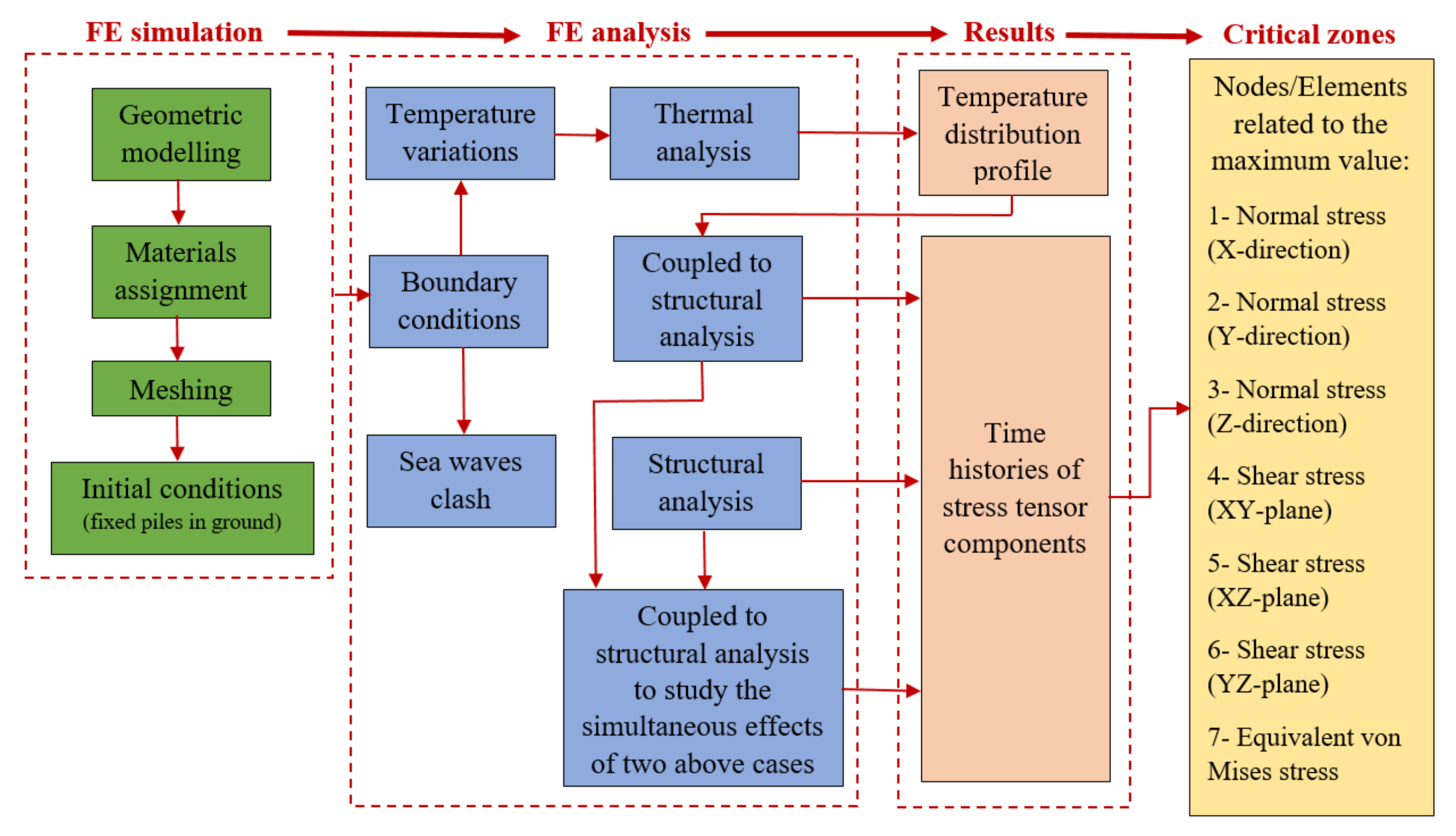
2. Methodology
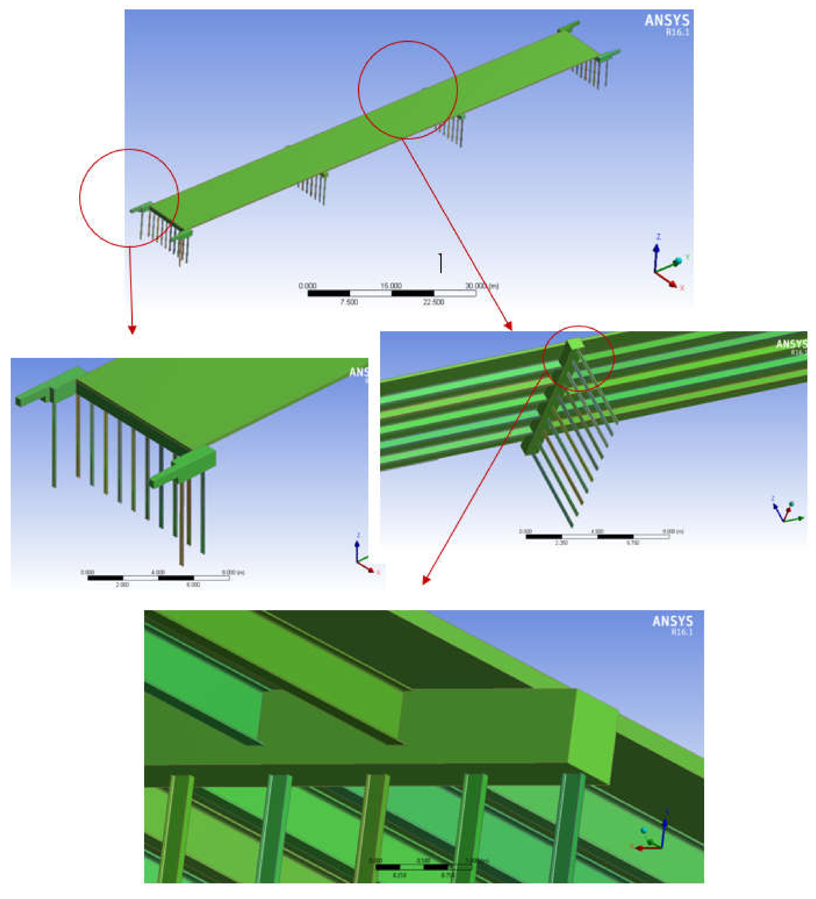
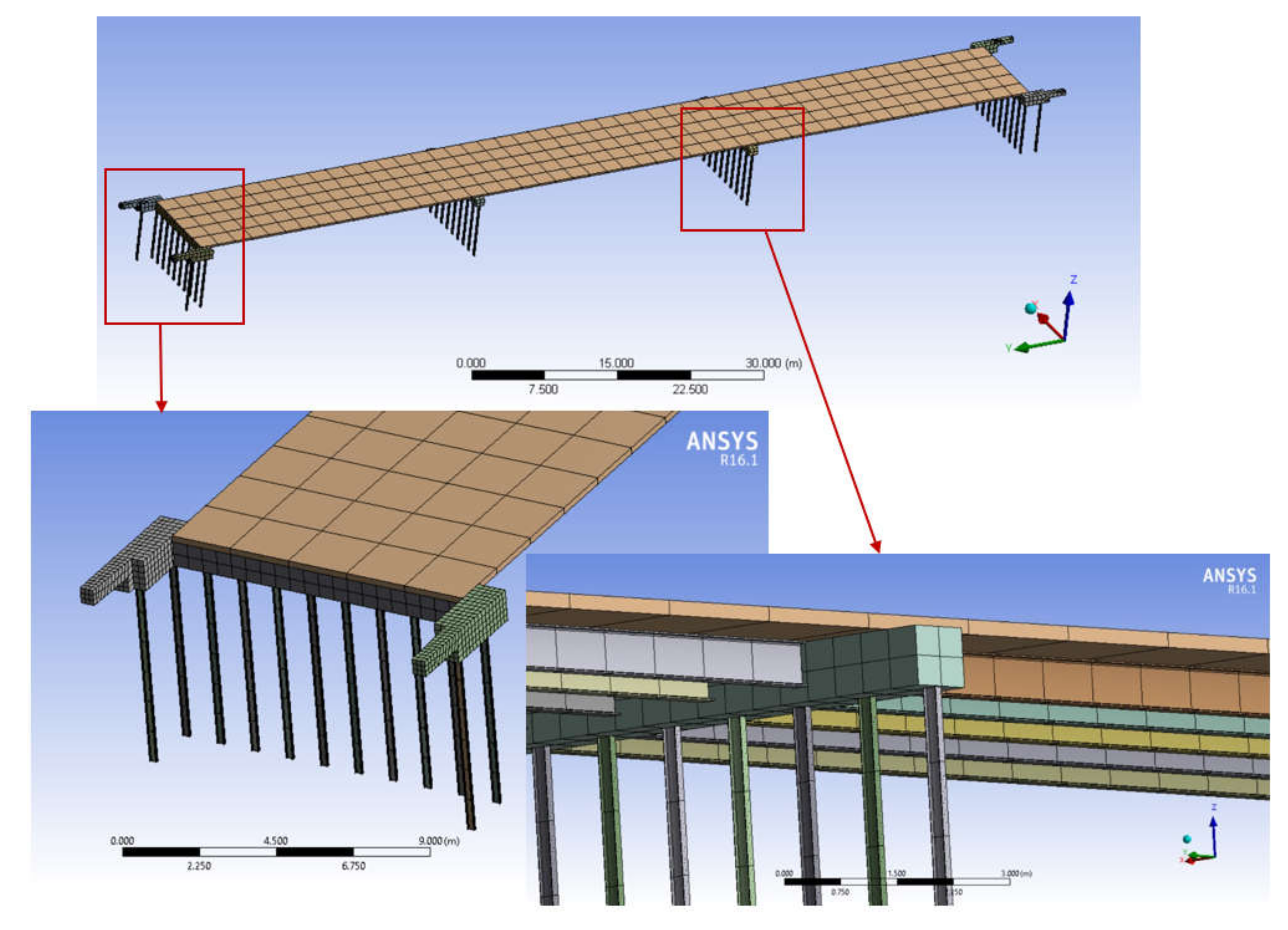
3. Geometry and Material
4. Finite Element Analysis
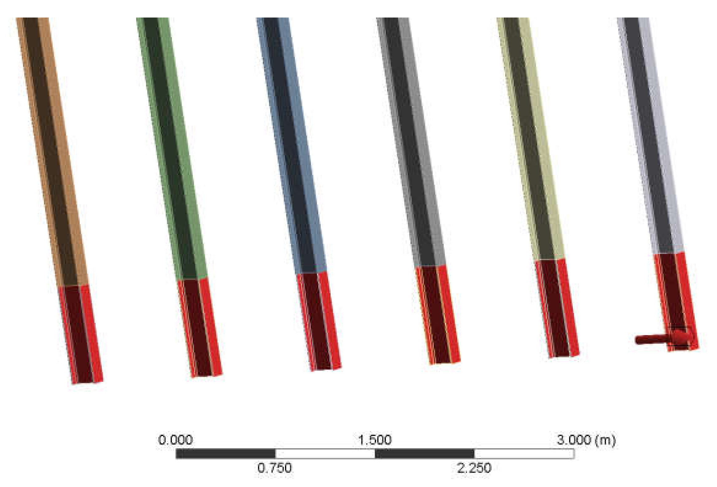
4.1. Meshing Procedure
4.2. Initial, Boundary, and Loading Conditions
4.3. Validation Process of the FEM in the Present Research
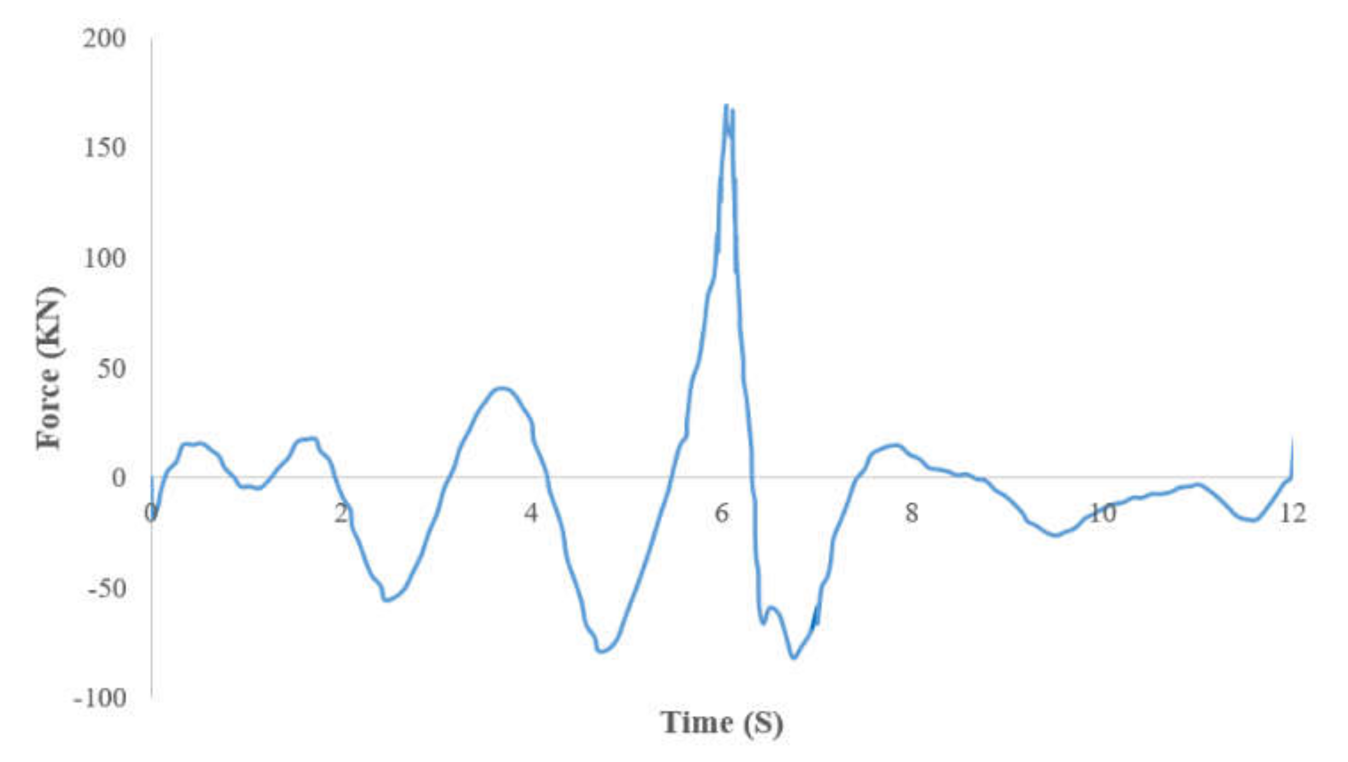
4.4. Structural Analysis for Assessment of Sea Waves Clash Impact
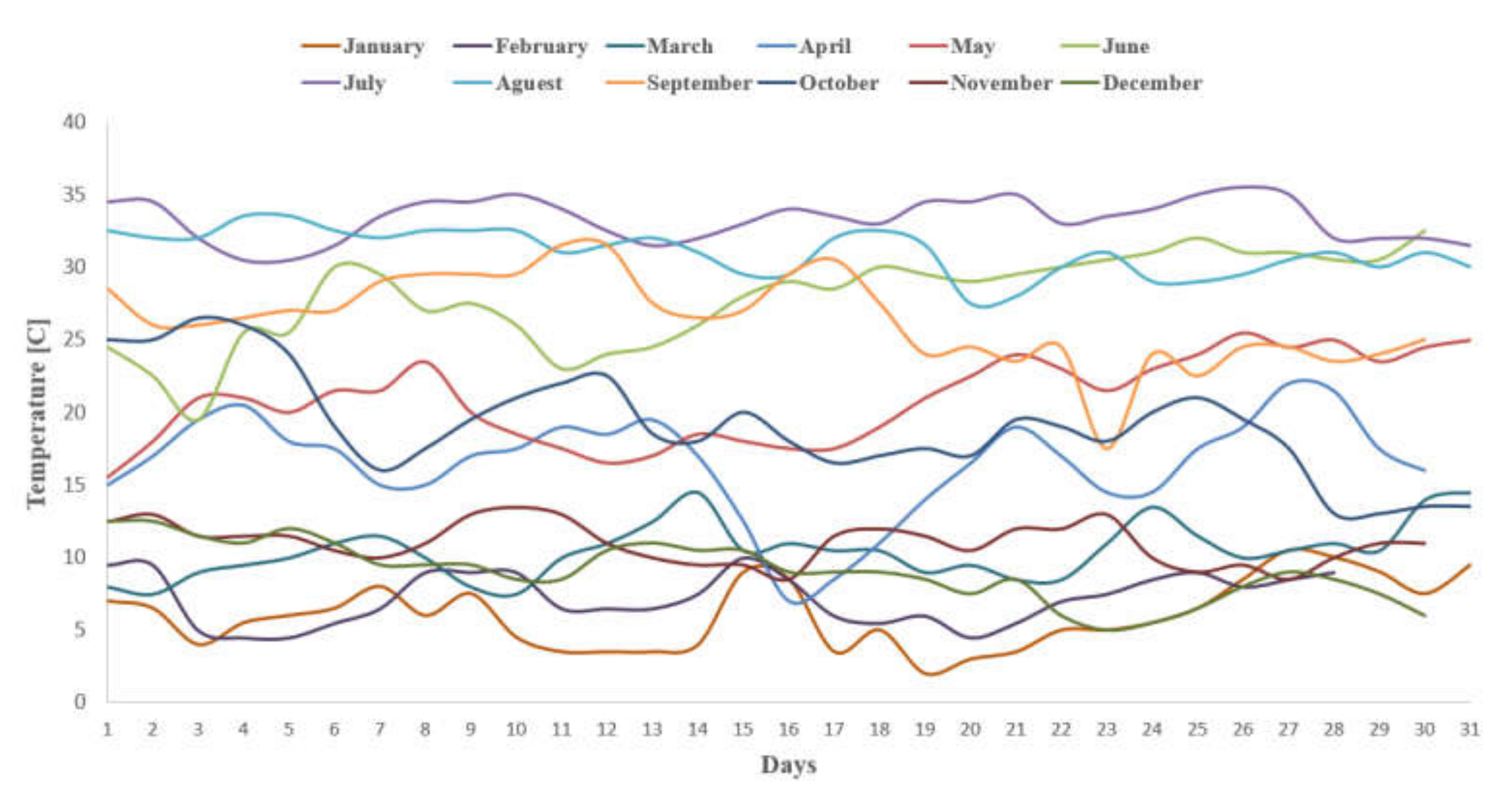
4.5. Coupling Structural-Thermal Analysis to Evaluate the Influence of Temperature Variations
4.6. Combination of the Two Above-Mentioned Cases
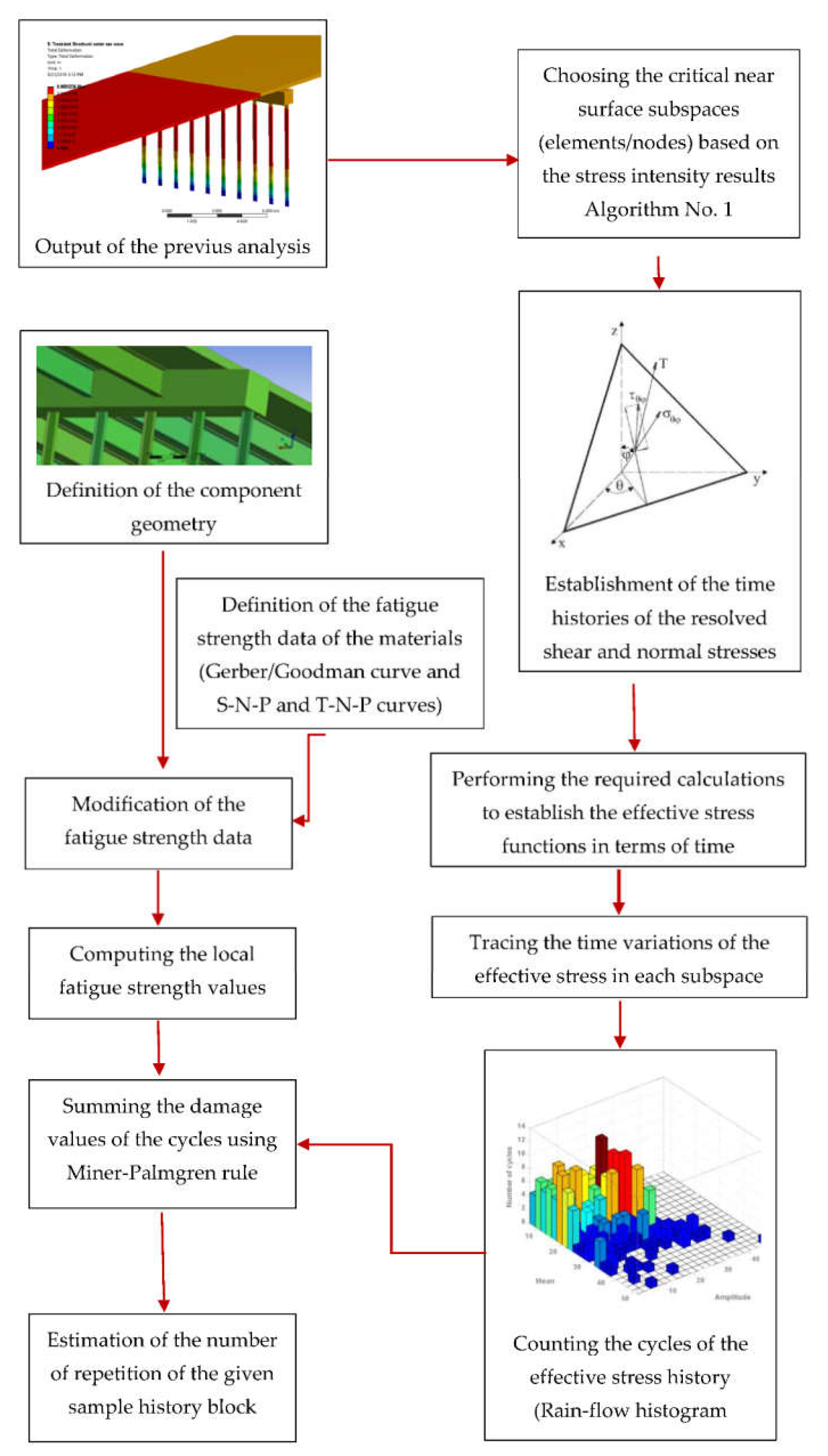
5. Fatigue Life Assessment
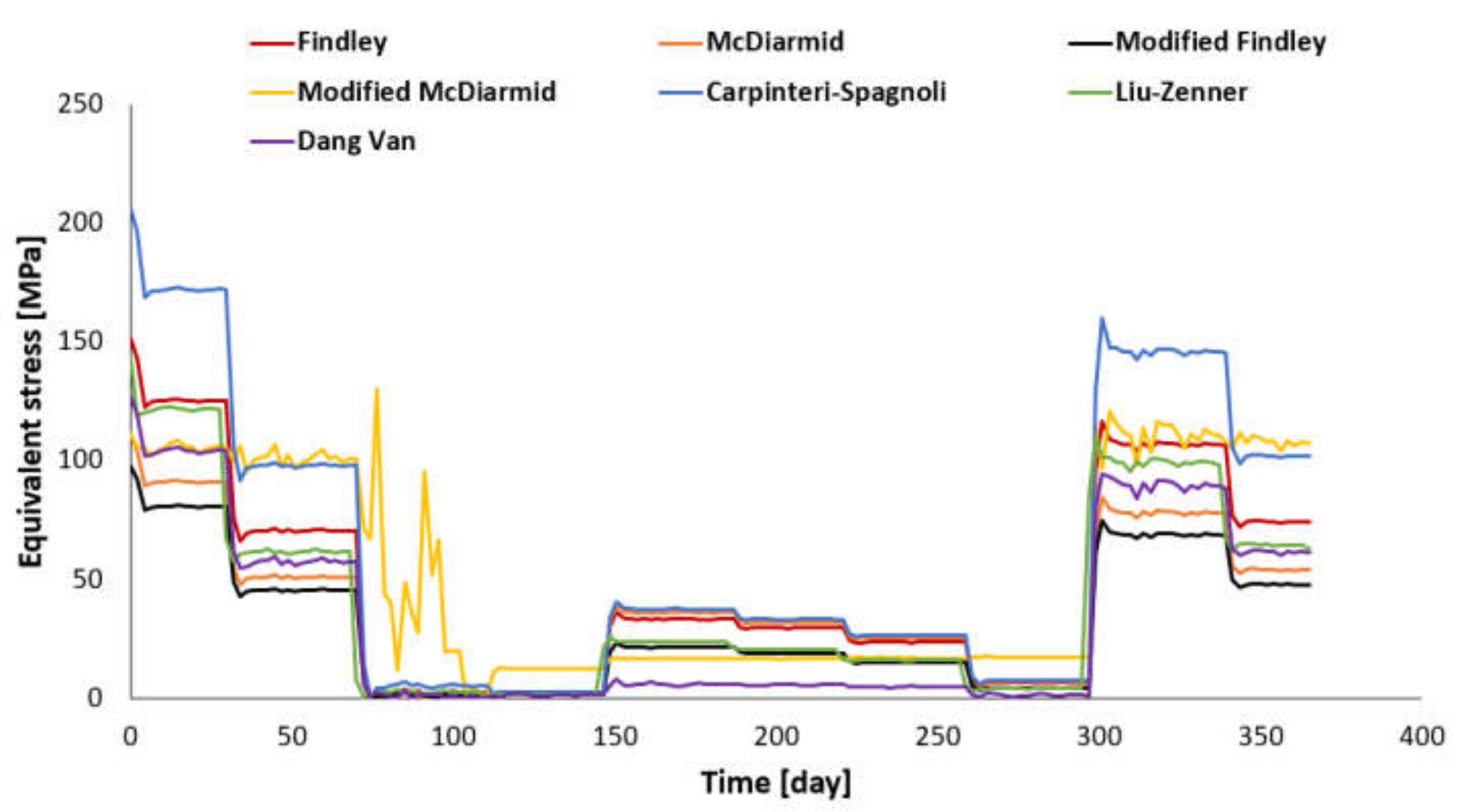
6. Results and Discussion
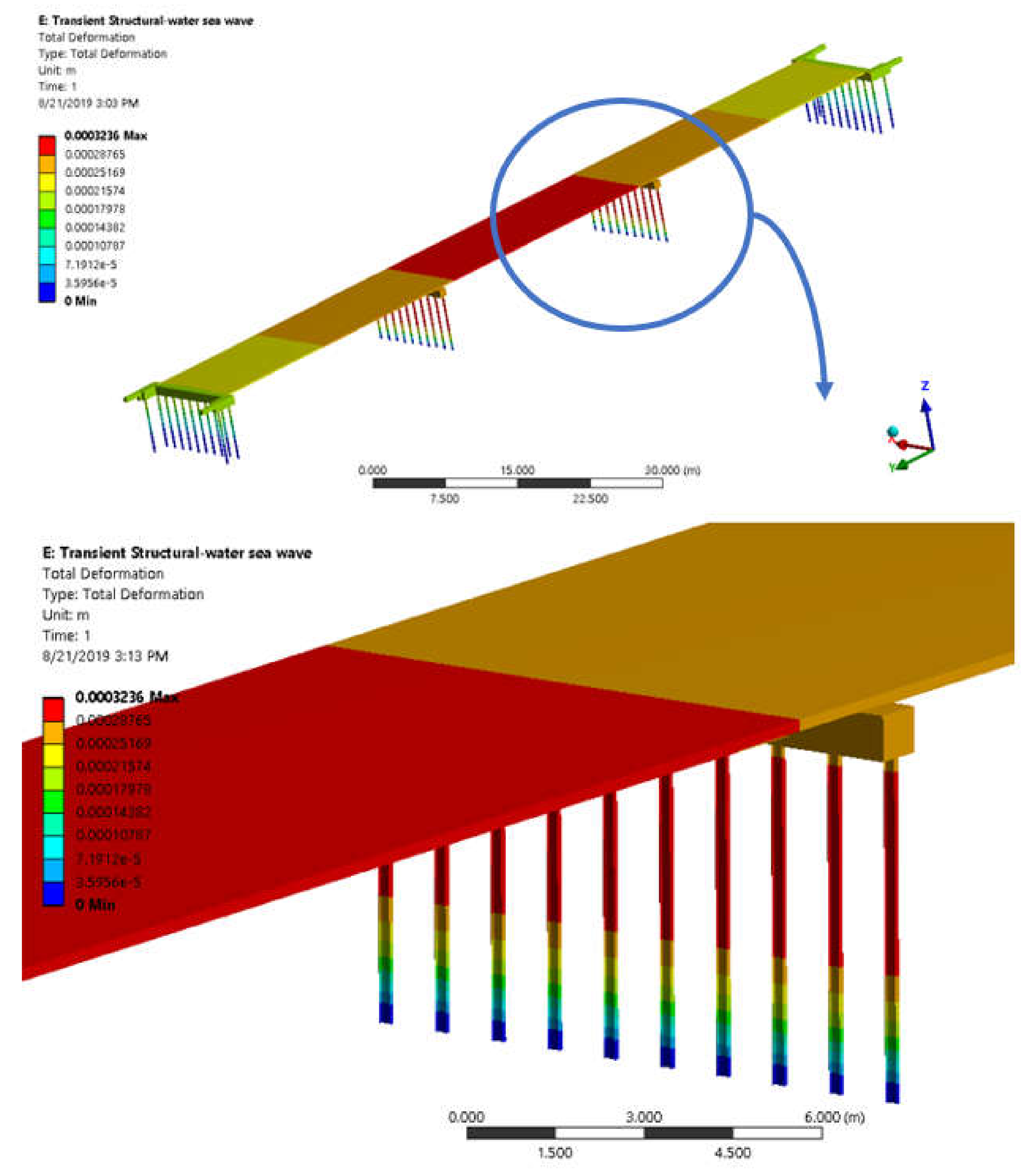
6.1. Critical Zones
6.2. Fatigue Life of Steel Piles on the Integrated Concrete Bridge
7. Conclusions
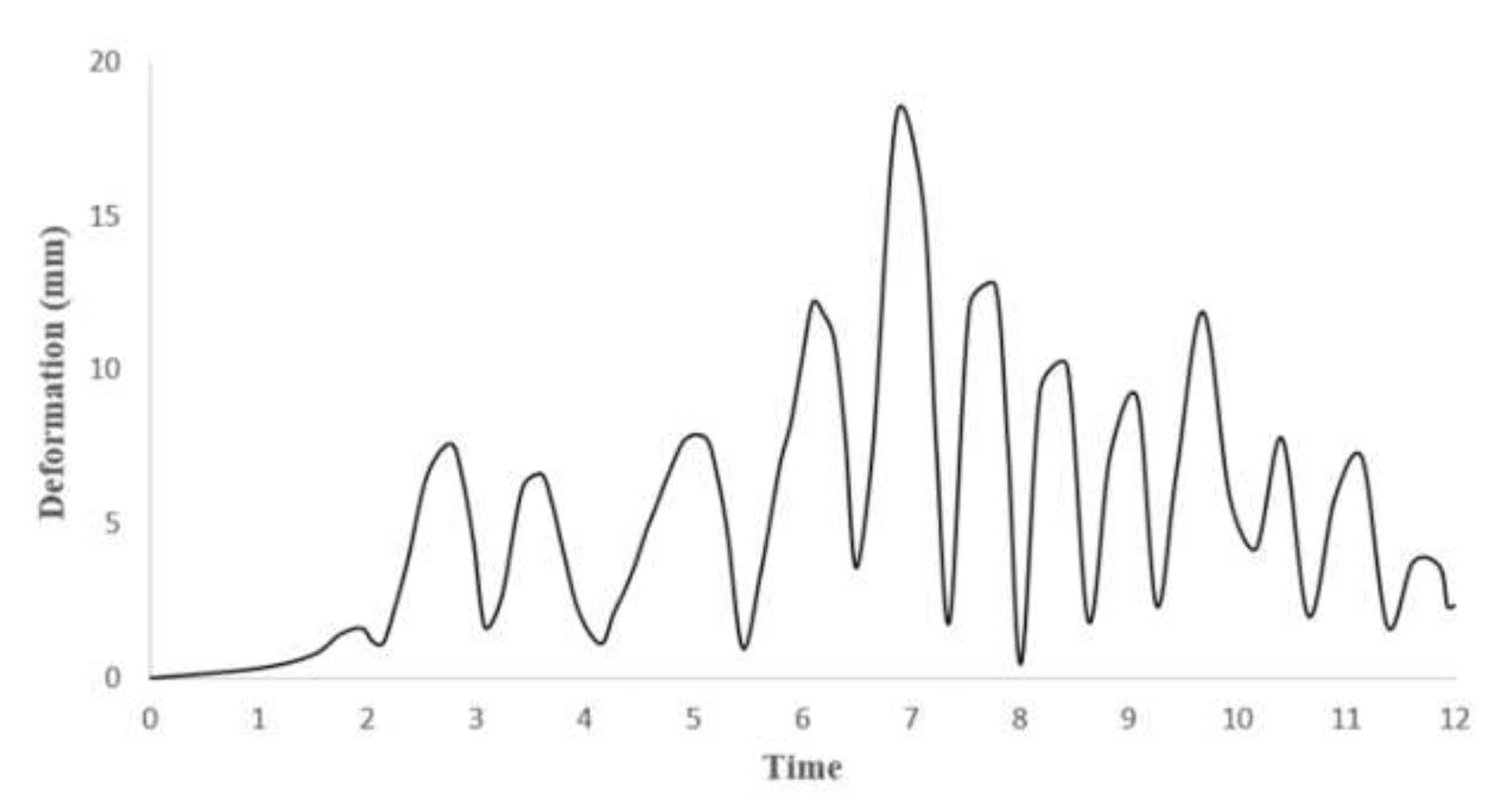
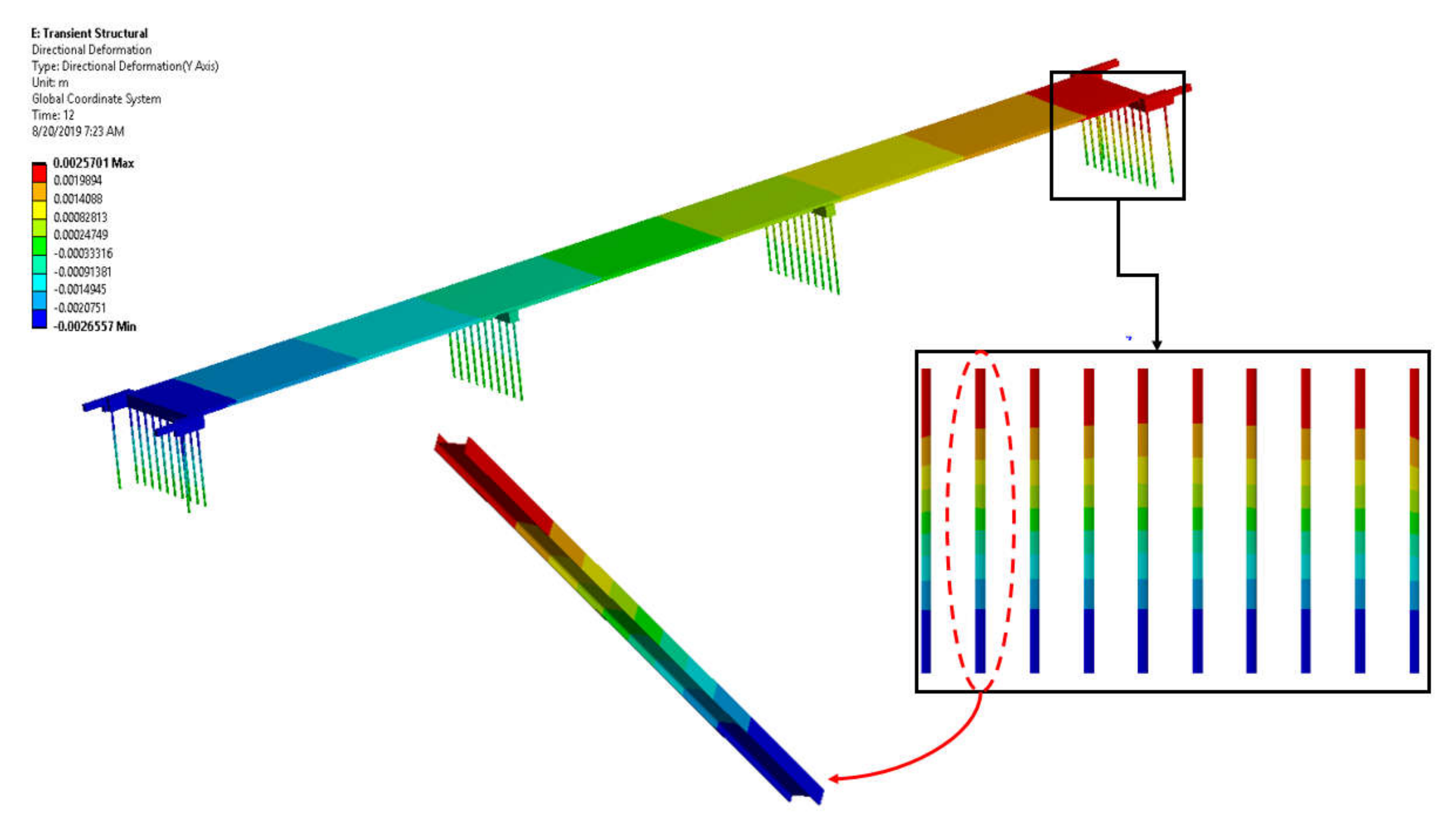
- The results of the structural analysis related to the sea waves clash indicated that the upper part of the middle pedestals underwent the highest deformations in the structure. The height of 3.8 m from the upper part of the pedestals underwent severe deformation, and the bottom of the pedestals remained without deformation (the height of 40 cm from the bottom).
- The results of the analyses revealed that all the critical elements are related to the upper part of the steel piles on either side of the bridge.
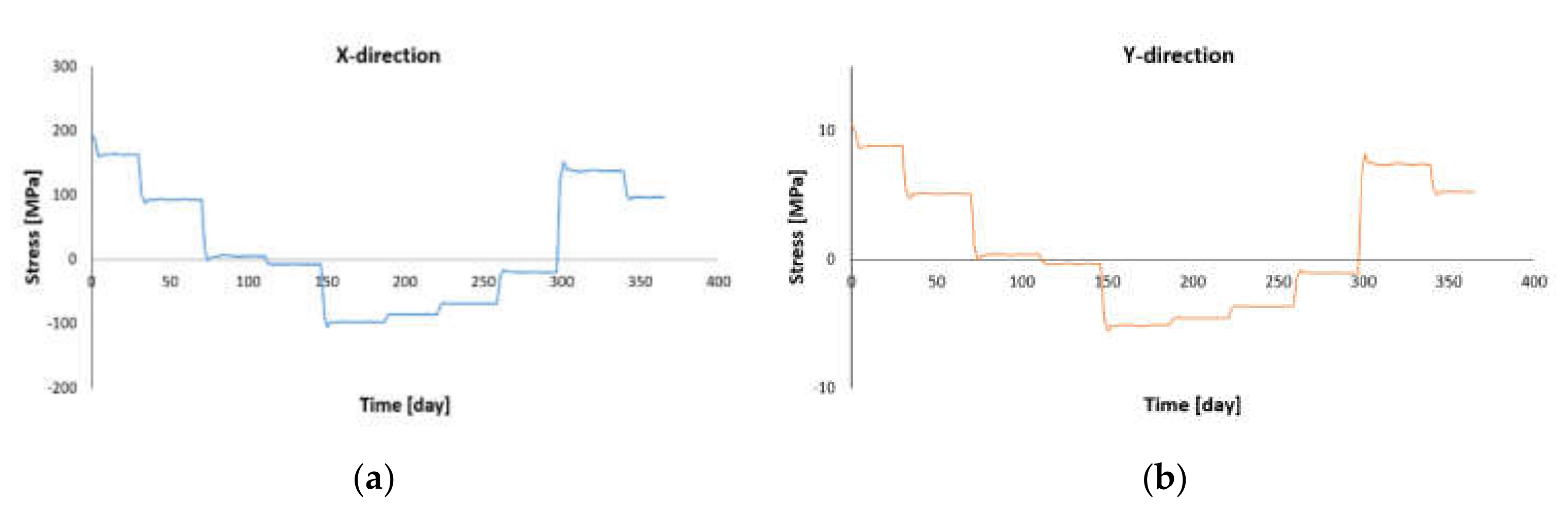
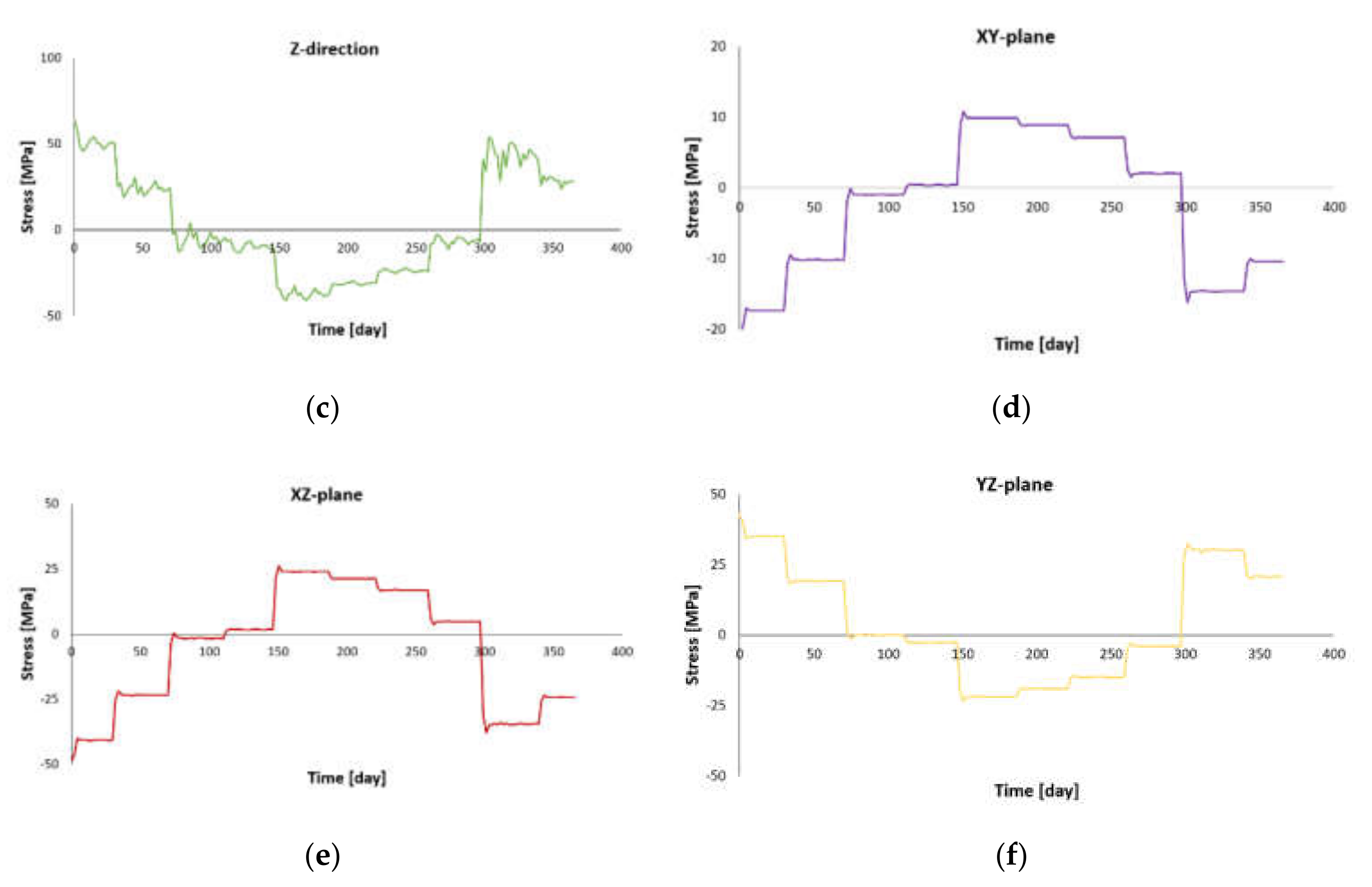
- The shortest fatigue life was related to the element with the maximum value of Y-direction stress (the longitudinal direction of the deck). The predominant load was the cyclic load due to bending at the top of the steel piles.
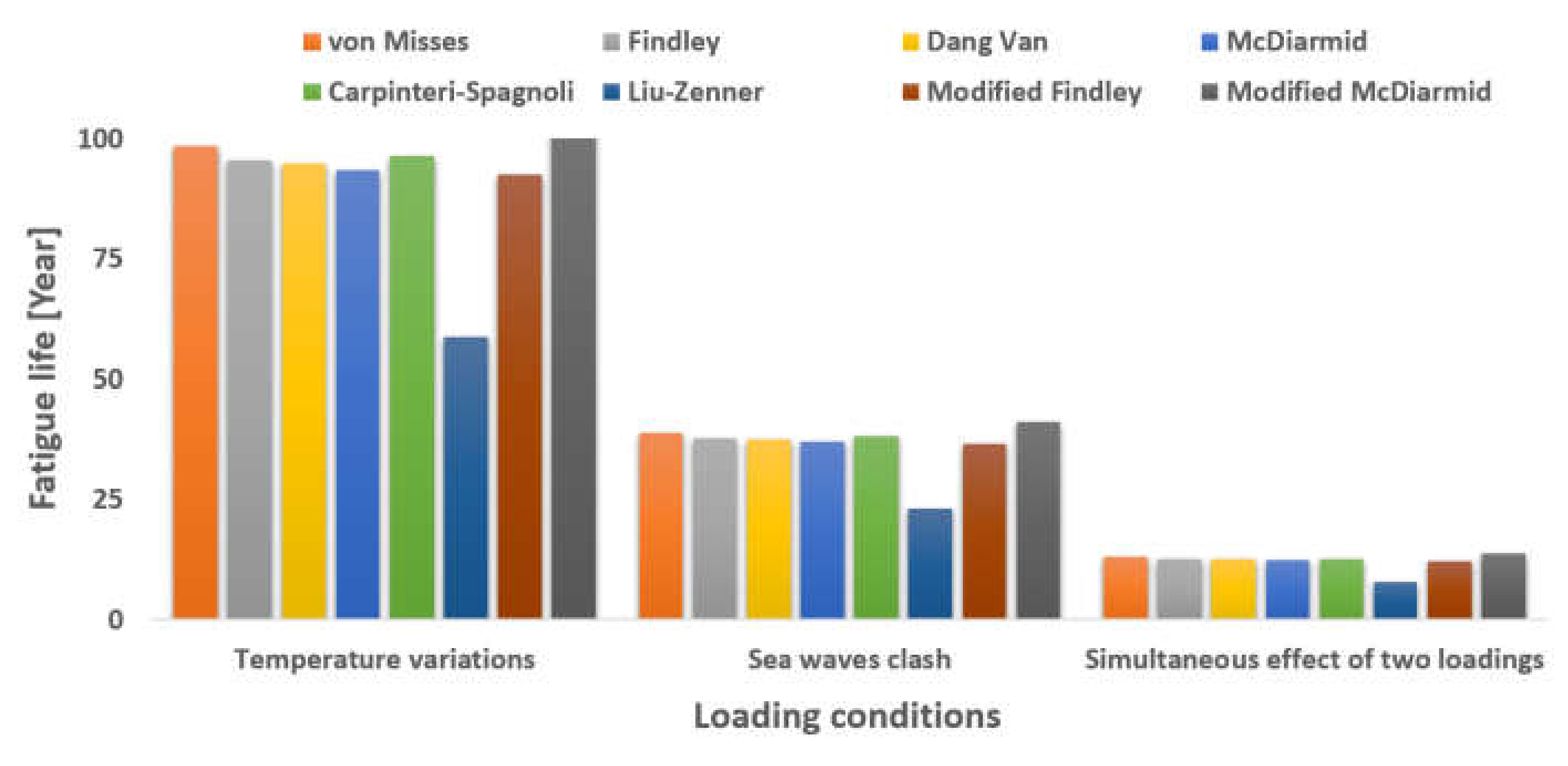
- The present study revealed that the lowest value of multiaxial fatigue lifetime belonged to the application of the Liu–Zenner criterion. In other words, the Liu–Zenner criterion is more conservative than the others.
- To reduce computational costs and avoid complex calculations, which may lead to computational error, the von Mises equivalent stress criterion was found to be useful with acceptable accuracy.
- The fatigue life of bridge steel piles under loading conditions of temperature variations, sea waves clash, and both loads simultaneously was estimated at 58.71, 23.25, and 7.75 years, respectively.
- The results indicated that the multiaxial fatigue life of the structure under the simultaneous effects of the two phenomena of daily temperature variations and the sea waves clash is reduced by approximately 87% and 66%, respectively, compared to the fatigue life of the structure under the effect of temperature changes and the effect of sea waves clash separately.
Author Contributions
Funding
Institutional Review Board Statement
Informed Consent Statement
Data Availability Statement
Acknowledgments
Conflicts of Interest
References
- Farrahi, G.H.; Ahmadi, A.; Kashyzadeh, K.R. Simulation of vehicle body spot weld failures due to fatigue by considering road roughness and vehicle velocity. Simul. Model. Pract. Theory 2020, 105, 102168. [Google Scholar] [CrossRef]
- Ahmadi, A.; Farrahi, G.H.; Kashyzadeh, K.R.; Azadi, S.; Jahani, K. A comparative study on the fatigue life of the vehicle body spot welds using different numerical techniques: Inertia relief and Modal dynamic analyses. Frat. Integrità Strutt. 2020, 14, 67–81. [Google Scholar]
- Nouri, M.; Ashenai-Ghasemi, F.; Rahimi-Sherbaf, G.; Kashyzadeh, K.R. Experimental and numerical study of the static performance of a hoop-wrapped CNG composite cylinder considering its variable wall thickness and polymer liner. Mech. Compos. Mater. 2020, 56, 339–352. [Google Scholar] [CrossRef]
- Ge, B.; Kim, S. Probabilistic service life prediction updating with inspection information for RC structures subjected to coupled corrosion and fatigue. Eng. Struct. 2021, 238, 112260. [Google Scholar] [CrossRef]
- Amiri, N.; Farrahi, G.H.; Kashyzadeh, K.R.; Chizari, M. Applications of ultrasonic testing and machine learning methods to predict the static & fatigue behavior of spot-welded joints. J. Manuf. Process. 2020, 52, 26–34. [Google Scholar]
- Ge, B.; Kim, S. Determination of appropriate updating parameters for effective life-cycle management of deteriorating structures under uncertainty. Struct. Infrastruct. Eng. 2021, 17, 1284–1298. [Google Scholar] [CrossRef]
- Kashyzadeh, K.R.; Rahimian Koloor, S.S.; Omidi Bidgoli, M.; Petrů, M.; Amiri Asfarjani, A. An Optimum Fatigue Design of Polymer Composite Compressed Natural Gas Tank Using Hybrid Finite Element-Response Surface Methods. Polymers 2021, 13, 483. [Google Scholar] [CrossRef] [PubMed]
- Soyama, H.; Chighizola, C.R.; Hill, M.R. Effect of compressive residual stress introduced by cavitation peening and shot peening on the improvement of fatigue strength of stainless steel. J. Mater. Process. Technol. 2021, 288, 116877. [Google Scholar] [CrossRef]
- Karimbaev, R.; Pyun, Y.S.; Maleki, E.; Unal, O.; Amanov, A. An improvement in fatigue behavior of AISI 4340 steel by shot peening and ultrasonic nanocrystal surface modification. Mater. Sci. Eng. A 2020, 791, 139752. [Google Scholar] [CrossRef]
- Maleki, E.; Unal, O.; Kashyzadeh, K.R.; Bagherifard, S.; Guagliano, M. A systematic study on the effects of shot peening on a mild carbon steel: Microstructure, mechanical properties, and axial fatigue strength of smooth and notched specimens. Appl. Surf. Sci. Adv. 2021, 4, 100071. [Google Scholar] [CrossRef]
- Maleki, E.; Unal, O.; Guagliano, M.; Bagherifard, S. The effects of shot peening, laser shock peening and ultrasonic nanocrystal surface modification on the fatigue strength of Inconel 718. Mater. Sci. Eng. A 2021, 810, 141029. [Google Scholar] [CrossRef]
- Soyama, H. Comparison between the improvements made to the fatigue strength of stainless steel by cavitation peening, water jet peening, shot peening and laser peening. J. Mater. Process. Technol. 2019, 269, 65–78. [Google Scholar] [CrossRef]
- Maleki, E.; Farrahi, G.H.; Kashyzadeh, K.R.; Unal, O.; Guagliano, M.; Bagherifard, S. Effects of conventional and severe shot peening on residual stress and fatigue strength of steel AISI 1060 and residual stress relaxation due to fatigue loading: Experimental and numerical simulation. Met. Mater. Int. 2021, 27, 2575–2591. [Google Scholar] [CrossRef]
- Maleki, E.; Unal, O.; Kashyzadeh, K.R. Effects of conventional, severe, over, and re-shot peening processes on the fatigue behavior of mild carbon steel. Surf. Coat. Technol. 2018, 344, 62–74. [Google Scholar] [CrossRef]
- Maleki, E.; Unal, O.; Kashyzadeh, K.R. Fatigue behavior prediction and analysis of shot peened mild carbon steels. Int. J. Fatigue 2018, 116, 48–67. [Google Scholar] [CrossRef]
- Maleki, E.; Unal, O.; Kashyzadeh, K.R. Efficiency analysis of shot peening parameters on variations of hardness, grain size and residual stress via Taguchi approach. Met. Mater. Int. 2019, 25, 1436–1447. [Google Scholar] [CrossRef]
- Maleki, E.; Unal, O.; Kashyzadeh, K.R. Surface layer nanocrystallization of carbon steels subjected to severe shot peening: Analysis and optimization. Mater. Charact. 2019, 157, 109877. [Google Scholar] [CrossRef]
- Kashyzadeh, K.R.; Arghavan, A. Study of the effect of different industrial coating with microscale thickness on the CK45 steel by experimental and finite element methods. Strength Mater. 2013, 45, 748–757. [Google Scholar] [CrossRef]
- Arghavan, A.; Reza Kashyzadeh, K.; Asfarjani, A.A. Investigating effect of industrial coatings on fatigue damage. Appl. Mech. Mater. 2011, 87, 230–237. [Google Scholar] [CrossRef]
- Kashyzadeh, K.R.; Maleki, E. Experimental investigation and artificial neural network modeling of warm galvanization and hardened chromium coatings thickness effects on fatigue life of AISI 1045 carbon steel. J. Fail. Anal. Prev. 2017, 17, 1276–1287. [Google Scholar] [CrossRef]
- Movahedifar, M.; Bolouri Bazaz, J.; Jafari, M.K. Influence of thermal elongation of integrated bridge deck on the amount of pressure applied to the bridges. In Proceedings of the 6th International Congress of Civil Engineering, Semnan, Iran, 26 April 2011. (In Persian). [Google Scholar]
- Najafi, H. Investigation of the influence of height deck on the behavioral parameters of integrated bridge retaining piles in clay soils with rock shallow floor. In Proceedings of the 10th International Congress of Civil Engineering, Tabriz, Iran, 29 April 2015. (In Persian). [Google Scholar]
- Arsoy, S. Proposed mathematical model for daily and seasonal thermal bridge displacements. Transp. Res. Rec. 2008, 16, 3–12. [Google Scholar] [CrossRef]
- Kong, B.; Cai, C.S.; Zhang, Y. Parametric study of an integral abutment bridge supported by prestressed precast concrete piles. Eng. Struct. 2016, 120, 37–48. [Google Scholar] [CrossRef]
- Amirahmad, A.; Al-Sinaidi, A.R. Analysis of Integral Bridges by Finite Element Method, the 2nd International Conference on Rehabilitation and Maintenance in Civil Engineering. Procedia Eng. 2013, 54, 308–314. [Google Scholar] [CrossRef] [Green Version]
- Abdollahnia, H.; Alizadeh Elizei, M.H.; Reza Kashyzadeh, K. Low-cycle fatigue behavior of H-shaped steel piles of an integral concrete bridge subjected to temperature variations. Mater. Today Proc. 2021, 46, 1657–1662. [Google Scholar] [CrossRef]
- Abdollahnia, H.; Alizadeh Elizei, M.H.; Reza Kashyzadeh, K. Fatigue life assessment of integral concrete bridges with H cross-section steel piles mounted in water. J. Fail. Anal. Prev. 2020, 20, 1661–1672. [Google Scholar] [CrossRef]
- Malajerdi, A.; Jahanmard, V.R.; Tabeshpour, M.R. Spectral analysis of impact waves on marine structures. In Proceedings of the Sixth International Conference on Offshore Industries, Tehran, Iran, 4–5 May 2015. (In Persian). [Google Scholar]
- Shoukry, S.N.; William, G.W.; Downie, B.; Riad, M.Y. Effect of moisture and temperature on the mechanical properties of concrete. Constr. Build. Mater. 2011, 25, 688–696. [Google Scholar] [CrossRef]
- Kashyzadeh, K.R. A new algorithm for fatigue life assessment of automotive safety components based on the probabilistic approach: The case of the steering knuckle. Eng. Sci. Technol. Int. J. 2020, 23, 392–404. [Google Scholar] [CrossRef]
- Farrahi, G.H.; Chamani, M.; Kashyzadeh, K.R.; Mostafazade, A.; Mahmoudi, A.H.; Afshin, H. Failure analysis of bolt connections in fired heater of a petrochemical unit. Eng. Fail. Anal. 2018, 92, 327–342. [Google Scholar] [CrossRef]
- Reza Kashyzadeh, K.; Farrahi, G.H.; Shariyat, M.; Ahmadian, M.T. The Role of Wheel Alignment Over the Fatigue Damage Accumulation in Vehicle Steering Knuckle. J. Stress Anal. 2018, 3, 21–33. [Google Scholar]
- Kashyzadeh, K.R.; Farrahi, G.H.; Shariyat, M.; Ahmadian, M.T. Experimental accuracy assessment of various high-cycle fatigue criteria for a critical component with a complicated geometry and multi-input random non-proportional 3D stress components. Eng. Fail. Anal. 2018, 90, 534–553. [Google Scholar] [CrossRef]
- Omidi Bidgoli, M.; Kashyzadeh, K.R.; Rahimian Koloor, S.S.; Petru, M.; Amiri, N. Optimum design of sunken reinforced enclosures under buckling condition. Appl. Sci. 2020, 10, 8449. [Google Scholar] [CrossRef]
- Reza Kashyzadeh, K.; Farrahi, G.H.; Shariyat, M.; Ahmadian, M.T. Experimental and finite element studies on free vibration of automotive steering knuckle. Int. J. Eng. 2017, 30, 1776–1783. [Google Scholar]
- Karalar, M.; Dicleli, M. Effect of thermal induced flexural strain cycles on the low cycle fatigue performance of integral bridge steel H-piles. Eng. Struct. 2016, 124, 388–404. [Google Scholar] [CrossRef]
- Nieslony, A. Determination of fragments of multiaxial service loading strongly influencing the fatigue of machine components. Mech. Syst. Signal Pract. 2009, 23, 2712–2721. [Google Scholar] [CrossRef]
- Mozafari, F.; Thamburaja, P.; Srinivasa, A.; Abdullah, S. Fatigue life prediction under variable amplitude loading using a microplasticity-based constitutive model. Int. J. Fatigue 2020, 134, 105477. [Google Scholar] [CrossRef]
- Mozafari, F.; Thamburaja, P.; Moslemi, N.; Srinivasa, A. Finite-element simulation of multi-axial fatigue loading in metals based on a novel experimentally-validated microplastic hysteresis-tracking method. Finite Elem. Anal. Des. 2021, 187, 103481. [Google Scholar] [CrossRef]


| Parameter | Unit | Value | |
|---|---|---|---|
| Structural Steel | Concrete | ||
| Density | 7850 | 2300 | |
| Young Modulus | GPa | 200 | 30 |
| Poisson’s Ratio | --- | 0.3 | 0.18 |
| Bulk Modulus | GPa | 166 | --- |
| Shear Modulus | GPa | 76.92 | --- |
| Tensile Yield Stress | Mpa | 250 | --- |
| Compressive Yield Stress | Mpa | 250 | --- |
| Tensile Ultimate Strength | Mpa | 460 | 5 |
| Compression Ultimate Strength | Mpa | --- | 41 |
| Parameter | Unit | Value | |
|---|---|---|---|
| Structural Steel | Concrete | ||
| Reference temperature | °C | 22 | 22 |
| Thermal expansion coefficient | 1.2 | 1.4 | |
| Parameter | Unit | Value |
|---|---|---|
| Strength Coefficient | Pa | 9.2 × 10⁸ |
| Strength Exponent | ---- | −0.106 |
| Ductility Coefficient | ---- | 0.213 |
| Ductility Exponent | ---- | −0.47 |
| Cyclic Strength Coefficient | Pa | 1 × 10⁹ |
| Cyclic Strain Hardening Exponent | ---- | 0.2 |
| Definition Type of the Equivalent Fatigue Stress | Cycles |
|---|---|
| Findley | 47 |
| McDiarmid | 48 |
| Dang van | 43 |
| Modified Findley | 47 |
| Modified McDiarmid | 55 |
| Carpinteri-Spagnoli | 48 |
| Liu-Zenner | 47 |
| Loading Conditions | Stress [Mpa] | |||||||
|---|---|---|---|---|---|---|---|---|
| Temperature variations | Elem. No | 38,732 | 38,732 | 40,879 | 40,101 | 42,018 | 38,684 | 38,732 |
| Value | 195.24 | 71.91 | 131.89 | 46.60 | 37.51 | 49.35 | 171.6 | |
| Sea waves clash | Elem. No | 56,042 | 56,203 | 61,308 | 61,234 | 56,177 | 56,180 | 5235 |
| Value | 239.1 | 142.2 | 135.56 | 51.7 | 61.7 | 52.4 | 194.3 | |
| Combination of two above-mentioned cases | Elem. No | 56,042 | 56,203 | 61,308 | 61,234 | 56,177 | 56,180 | 5235 |
| Value | 248.7 | 149.3 | 146.51 | 52.5 | 64.7 | 58.4 | 203 |
Publisher’s Note: MDPI stays neutral with regard to jurisdictional claims in published maps and institutional affiliations. |
© 2021 by the authors. Licensee MDPI, Basel, Switzerland. This article is an open access article distributed under the terms and conditions of the Creative Commons Attribution (CC BY) license (https://creativecommons.org/licenses/by/4.0/).
Share and Cite
Abdollahnia, H.; Alizadeh Elizei, M.H.; Reza Kashyzadeh, K. Multiaxial Fatigue Life Assessment of Integral Concrete Bridge with a Real-Scale and Complicated Geometry Due to the Simultaneous Effects of Temperature Variations and Sea Waves Clash. J. Mar. Sci. Eng. 2021, 9, 1433. https://doi.org/10.3390/jmse9121433
Abdollahnia H, Alizadeh Elizei MH, Reza Kashyzadeh K. Multiaxial Fatigue Life Assessment of Integral Concrete Bridge with a Real-Scale and Complicated Geometry Due to the Simultaneous Effects of Temperature Variations and Sea Waves Clash. Journal of Marine Science and Engineering. 2021; 9(12):1433. https://doi.org/10.3390/jmse9121433
Chicago/Turabian StyleAbdollahnia, Hamid, Mohammad Hadi Alizadeh Elizei, and Kazem Reza Kashyzadeh. 2021. "Multiaxial Fatigue Life Assessment of Integral Concrete Bridge with a Real-Scale and Complicated Geometry Due to the Simultaneous Effects of Temperature Variations and Sea Waves Clash" Journal of Marine Science and Engineering 9, no. 12: 1433. https://doi.org/10.3390/jmse9121433